

Power Plant Transients including Hydraulic Short Circuit Operation Mode

Institute of Fluid Mechanics and Hydraulic Machinery (IHS), University of Stuttgart, Pfaffenwaldring 10, 70569 Stuttgart, Germany
*
Author to whom correspondence should be addressed.
Energies 2023, 16(11), 4492; https://doi.org/10.3390/en16114492
Submission received: 17 March 2023
/
Revised: 24 May 2023
/
Accepted: 29 May 2023
/
Published: 2 June 2023
(This article belongs to the Special Issue Selected Contributions of the ViennaHydro 2022)
Abstract
:Within the XFLEX HYDRO project, the possibility of increasing the flexibility of hydro power plants to support the Electric Power System (EPS) is investigated. The flexibility of the pumped-storage power plant Frades 2, as the target, should increase by extending the operating range for each unit and by using the hydraulic short circuit (HSC) operation mode. Transient investigations of the additional plant conditions are performed to ensure the safety of the plant. With a 1D model of the entire hydro power plant including both pump-turbines, valves, surge tanks, and the water-bearing components, extensive calculations are carried out to verify the safety of the existing plant for extended operation conditions. In particular, the study focuses on the synchronous and asynchronous emergency shutdowns of the plant in the new operating conditions as well as other operation-related power plant transients regarding the HSC mode. With the results presented in this paper, the flexibility of the plant Frades 2 can be increased. Delayed emergency shutdowns are identified as particularly critical during the study and should always be given additional consideration in transient investigations.
1. Introduction
Currently, there is a trend towards more renewable energies and less energy supply with conventional power plants. This leads to increasing requirements for hydro power plants [1], for example, the support of the Electric Power System (EPS) with more flexibility services [2,3]. Flexible provision of energy ensures an important contribution to grid stability. The resulting off-design operating points and the transient control processes must be extensively investigated prior to commissioning to ensure the safety of the power plant.
Various studies include transient water hammer simulations for the entire hydro power plant with all water-bearing elements such as the piping system, valves, bifurcations, surge tanks, and hydraulic units for all operating points [4], control processes [5,6,7], and emergency scenarios.
In addition to water hammer analysis, detailed flow simulation of the piping system including bifurcations are important to assess the dynamics of the pressure on the piping wall as well as the resulting inflow conditions to the hydraulic machines to prevent damage in hydraulic short circuit operation [8,9].
Other investigations directly focused on the hydraulic units. Particular attention was paid to the investigation of flow effects applying numerical flow field simulation methods and finite element methods to assess the structural dynamic behaviour of machine components and their related lifetime. Studies include the assessment of the influence of flow resolution and cavitation effects [10] on prediction accuracy. Recent interest is also related to the prediction of dynamic loading within hydraulic units under operational transients treated with simultaneously coupled approaches between 1D plant dynamic approaches and flow field simulation [11,12,13]. The effect of different numerical approaches for flow simulation on the stress and strain distribution within the structure and the influence on the service life of the runner was analysed too [14,15].
The increase in flexibility of hydro power plants and the possible influence on grid stability is investigated within the XFLEX HYDRO [16] project funded by the European Union. In that context, the existing pumped-storage power plant Frades 2, is analysed. That plant is located in the northwest of Portugal. The rated gross head is 420 m, varying between 414 m and 432 m. Both 390 MW reversible pump-turbines are equipped with double fed induction machines (DFIM) enabling the rotational speed to be adjusted within a certain range [17,18].
The objective is to increase the flexibility of the plant by extending the operating range for each unit and introducing hydraulic short circuit (HSC) operation, an extended operating mode of the plant. In addition to the currently permitted one or two machine operations in pure turbine or pump mode, in HSC mode, one machine operates as a pump and one as a turbine at the same time. By operating the plant in HSC mode, the range of the total power output of the plant can be increased and thus better adapted to the requirements of the Electric Power System.
To make a statement regarding the possibility and safety of the plant operating in the new operation modes, several studies have been performed. These include flow field simulations and structural analysis of the pump-turbines and of the headwater bifurcation [8] as well as a test campaign of the Frades 2 model unit in the laboratory. Furthermore, transient simulations are performed for extended operating points being presented within this paper.
2. Simulation Model of the Hydro Power Plant
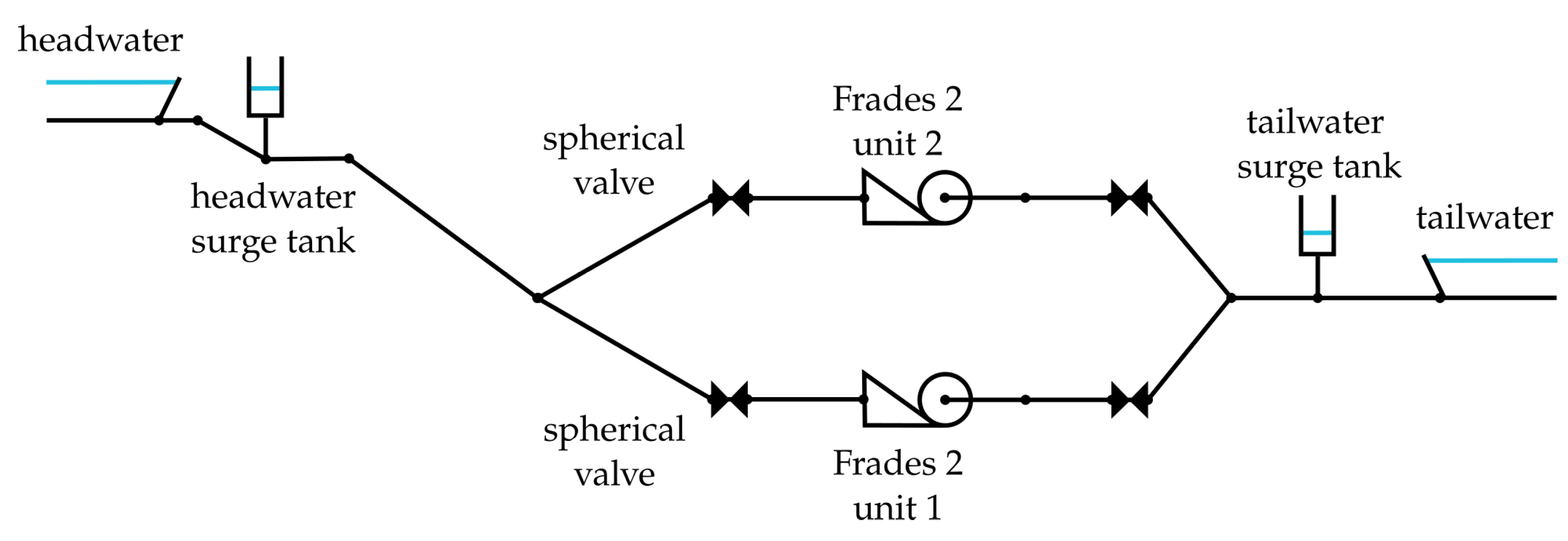
All simulations are carried out with a 1D simulation program [19] for plant transient simulations using the Method of Characteristics. The simulation model of the hydro power plant Frades 2 includes the headwater (HW) and tailwater (TW) reservoir, one headwater and one tailwater surge tank (HW ST and TW ST), pump-turbine unit 1 and unit 2, a spherical valve (main inlet valve, MIV) in front of each unit, and the pipe system, as shown in Figure 1.
The dimensions and the friction coefficient of the pipe system as well as the modelling of both surge tanks are adopted from an existing transient simulation report provided by Voith Hydro, the OEM (Original Equipment Manufacturer) of the hydro power plant. The pump-turbine governor parameters of the guide vanes are not available in the pure hydraulic model of the hydro power plant. Therefore, predefined linear opening and closing laws are used for the MIV and the guide vanes. In the case of emergency shutdown, the closing process is mechanical.
The pump-turbines are modelled using four-quadrant characteristics measured on a model turbine at Voith Hydro’s laboratory test facility under quasi-steady state conditions. Experience shows that the prototype characteristics deviate from the model tests in the real transient case. This observation is verified with a complex and time-consuming coupled simulation approach for a transient of another pumped-storage power plant [12]. As such data are not available for this study, the laboratory measured four-quadrant characteristics are utilized in the transient case [20]. The inertia of the fluid inside the machines is modelled by additional frictionless pipe sections connected to the machines.
The spherical valve is described in terms of its known discharge characteristic. Transient simulations are performed and compared with existing results for several load cases. The deviations in the transient results are insignificant, and the model is thus assessed as verified.
3. Investigation of the Hydro Power Plant and Results
The simulations regarding the hydro power plant Frades 2 are divided into two parts. The first part focuses on the identification of all possible operation combinations of both units within the continuous operation regime.
The second part focuses on the transient operation modes of the power plant for identified machine operation combinations. The start-up process of the hydro power plant and the change between operating points is analysed. Furthermore, the emergency shutdown from all possible operating points is investigated. This includes emergency shutdown with and without closing the MIV and the guide vanes. This results in many possible investigations, e.g., emergency shutdown in just one unit, synchronous emergency shutdowns in both units, and time-shifted emergency shutdown.
3.1. Existing and Extended Operation Combinations within the Continuous Operation Regime
An input parameter matrix which includes all possible plant operating points of the existing and the extended power plant operating range is presented in Table 1.
The input matrix includes the elevation of the headwater reservoir (headwater level, HWL) and the elevation of the tailwater reservoir (tailwater level, TWL). In each case, the highest and lowest levels as well as the rated water levels are investigated. The rotational speed (n1 and n2) and the opening angle of the guide vanes (Y1 and Y2) of each unit are modified within the given limits. The limits depend on the operating mode (turbine or pump mode, one or two units in use). The values in the brackets show how many values are covered between minimum and maximum values. The opening angle is tabulated both normalized to the opening angle of 24.4° as well as in degrees.
In the simulation, all possible combinations of both units resulting from the input matrix are considered. The possible combinations are: both units in turbine mode, both units in pumping mode, using HSC mode, and only one unit operating in pump or turbine mode. The overall number of simulations is reduced due to the symmetry of the system pipe layout. Nevertheless, those mentioned operating point combinations lead to approximately 7500 different simulations for each hydraulic head. The variation of head and rotational speed in association with operation range expansion beyond original admissible range requires the analysis of all combinations to maintain the structural integrity of the existing equipment for the future.
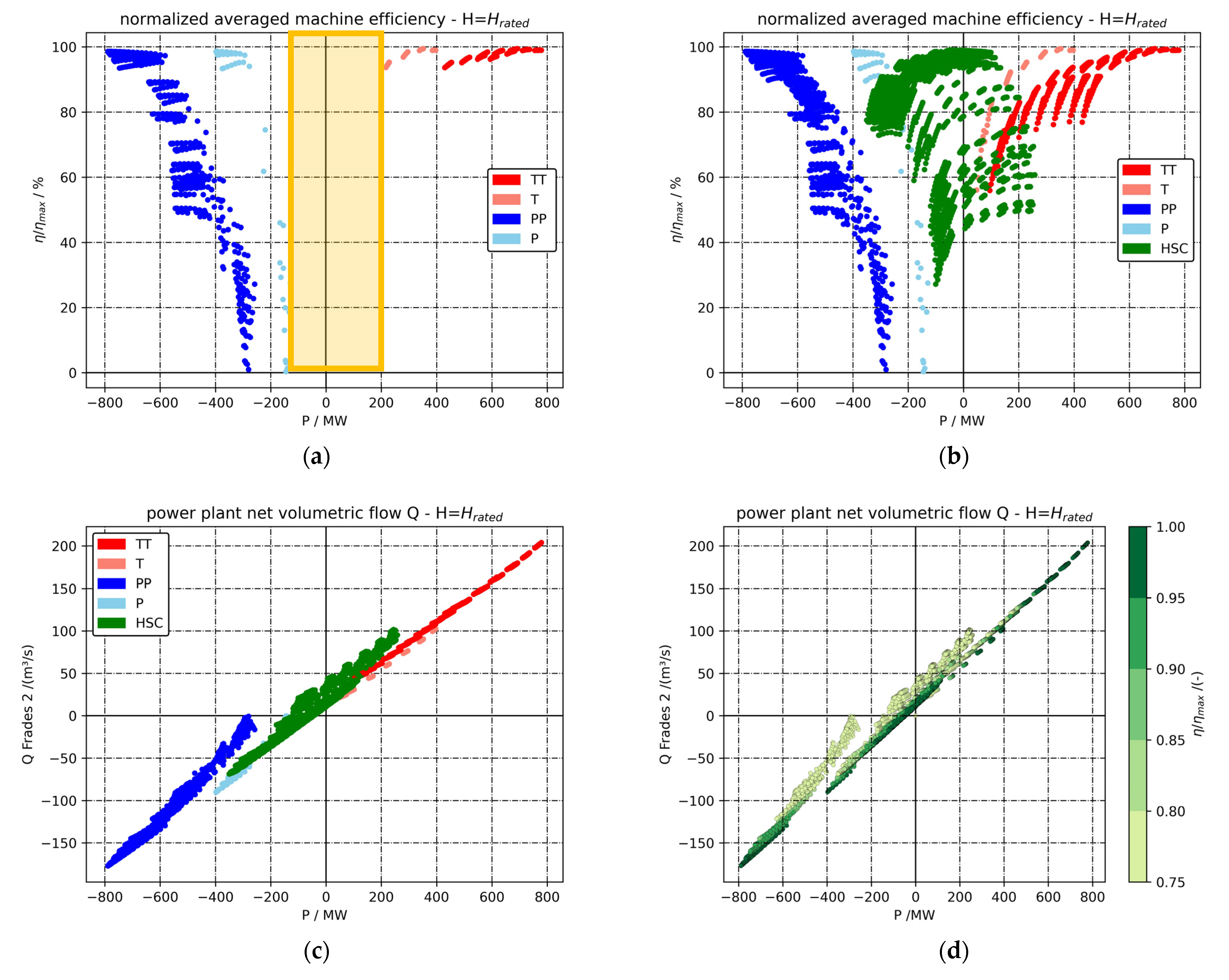
The current operating range of Frades 2 at rated head is shown in Figure 2a. The data show the normalized averaged machine efficiency versus the total mechanical power P, the sum of the mechanical power of each unit. The power in turbine mode is defined positive, in pump mode negative. The averaged machine efficiency, calculated from the individual efficiencies of both machines , is normalized to the maximal occurring averaged machine efficiency ηmax.
Each current possible combination of the units is represented in the diagram with one dot indicating the operation mode by colour code. Operating mode abbreviation denotes: TT, both units in turbine mode; T, just one unit in turbine mode; PP, both units in pump mode; or P, just one unit in pump mode. With the current combination, a total power output between about −150 MW and 200 MW is not possible, shown with the orange box in Figure 2a.
The extended operating range of each unit and the use of HSC significantly expands the operating range of Frades 2 (Figure 2b). A total power output in the range of −800 MW to 800 MW is achieved with a high normalized average machine efficiency for nearly every required power value. For example, if a total power output of 200 MW is required, the operating modes HSC, T, and TT are possible. To get the highest normalized averaged machine efficiency, the operation of just one turbine is recommended. Operating the machines at operating points with high machine efficiencies results in low mechanical loads on the runners.
The choice of the individual machine operation point, especially for HSC, affects the flow rate towards the reservoirs (Figure 2c,d). Higher normalized average machine efficiency is beneficial to reservoir water levels. In this case, less water is consumed in generator operation and more water is pumped to the upper reservoir in pumping operation. However, under certain circumstances, the operator may decide differently.
A significant expansion of the operating range is also observed for the maximum and minimum head.
3.2. Simulation of Operational Power Plant Transients
3.2.1. Synchronous Emergency Shutdown
All power plant conditions defined via Table 1 are used as starting operating conditions for the synchronous emergency shutdown of both units. All simulations start with a steady state condition followed by a synchronous load rejection of both units from the electrical grid. Depending on the simulation case, the wicket gates (WGs) of both units or the spherical valves in front of the corresponding unit start to close synchronously as quick as possible according to the respective closing law.
The temporary permissible extreme values under transient conditions for maximum rotational speed |n|max, maximum spiral case pressure pspiral case max, minimum draft tube pressure pdraft tube min, and maximum and minimum water levels in both surge tanks (zHW ST max/min and zTW ST max/min) are defined during the original plant layout and thus are evaluated. Regarding the maximum shaft torque of each unit |T|max, only the rated torque is available. An individual evaluation of the extreme shaft torque values is required by the OEM. The maximum pressure in the spiral case pspiral case max is referred to elevation 207.0 m.a.s.l. and a pipe diameter of 2.90 m and the minimum pressure in the draft tube inlet pdraft tube min to elevation 205.92 m.a.s.l. and a pipe diameter of 2.61 m.
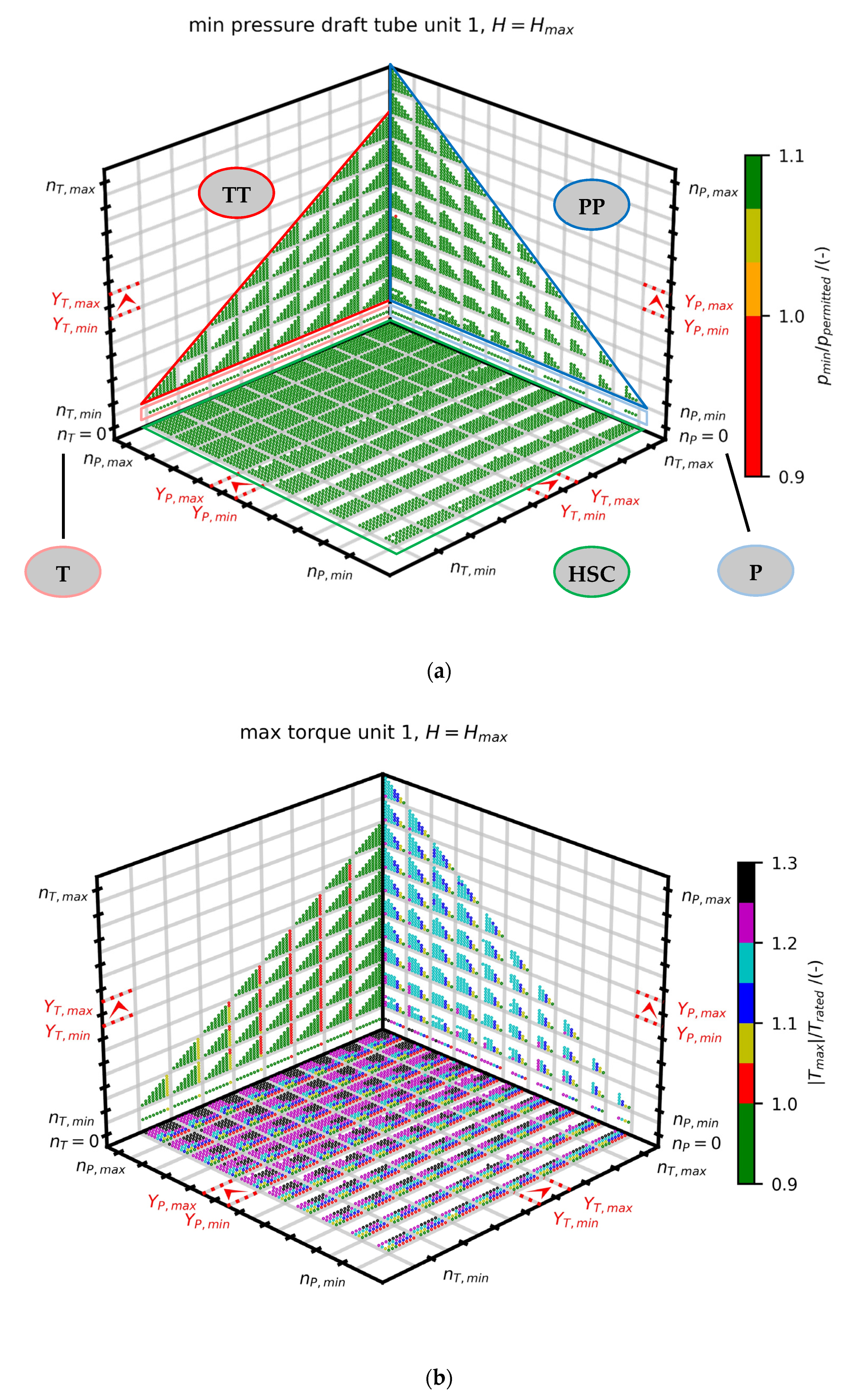
The aim is to display all 7500 simulation results in one diagram as presented in Figure 3a. Each simulation is represented by one dot and defined by the steady state starting operating point (rotational speed n and opening angle of the wicket gates Y) of both units, as seen in Figure 3a. The colour of the dot is an indicator of the analysed extreme value.
The possible unit combinations of the plant in HSC mode are displayed inside a green frame on the base area. The base area itself is divided into several grey boxes using a grid. Within each grey box, the rotational speed combination of the two units is constant. The rotational speed n increases from the minimum to the maximum rotational speed in defined steps according to Table 1, displayed at the edges of the diagram. In each box, the opening angle of the wicket gates increases from minimum to maximum opening angle in defined steps with values presented in Table 1. The direction of the increase, which also applies to the other boxes, is shown by red arrows on the edges.
In addition, all other possible combinations of the two units are displayed in the diagram: both units in turbine mode TT (red frame), both units in pumping mode PP (blue frame), and only one unit operating in turbine T (light red) or pumping mode P (light blue). Due to the symmetry of the water-bearing system and the synchronous emergency shutdown, the number of simulations in pump and turbine mode could be reduced.
A statement about the extreme values is only possible for the simulations marked with a dot in the diagrams. Due to the large operating range selected, unfavourable combinations of rotational speed and opening angle of the wicket gates may occur, especially in pumping or HSC mode, causing the simulation not to start. As a consequence, no result is presented.
A selection of the simulated extreme values is presented in Figure 3 and Figure 4 and an overview of all calculated extreme values is tabulated in Table 2. The maximum temporary rotational speed of both units remains below the permissible extreme value in all simulation cases.
The maximum observed temporary shaft torque occurs during synchronous emergency shutdown with closing spherical valves at maximum head and is approximately 130% of the rated shaft torque, as seen in Table 2 (dashed frame) and Figure 3b. Besides the pumping operation of both units, the highest shaft torque values appear in HSC mode.
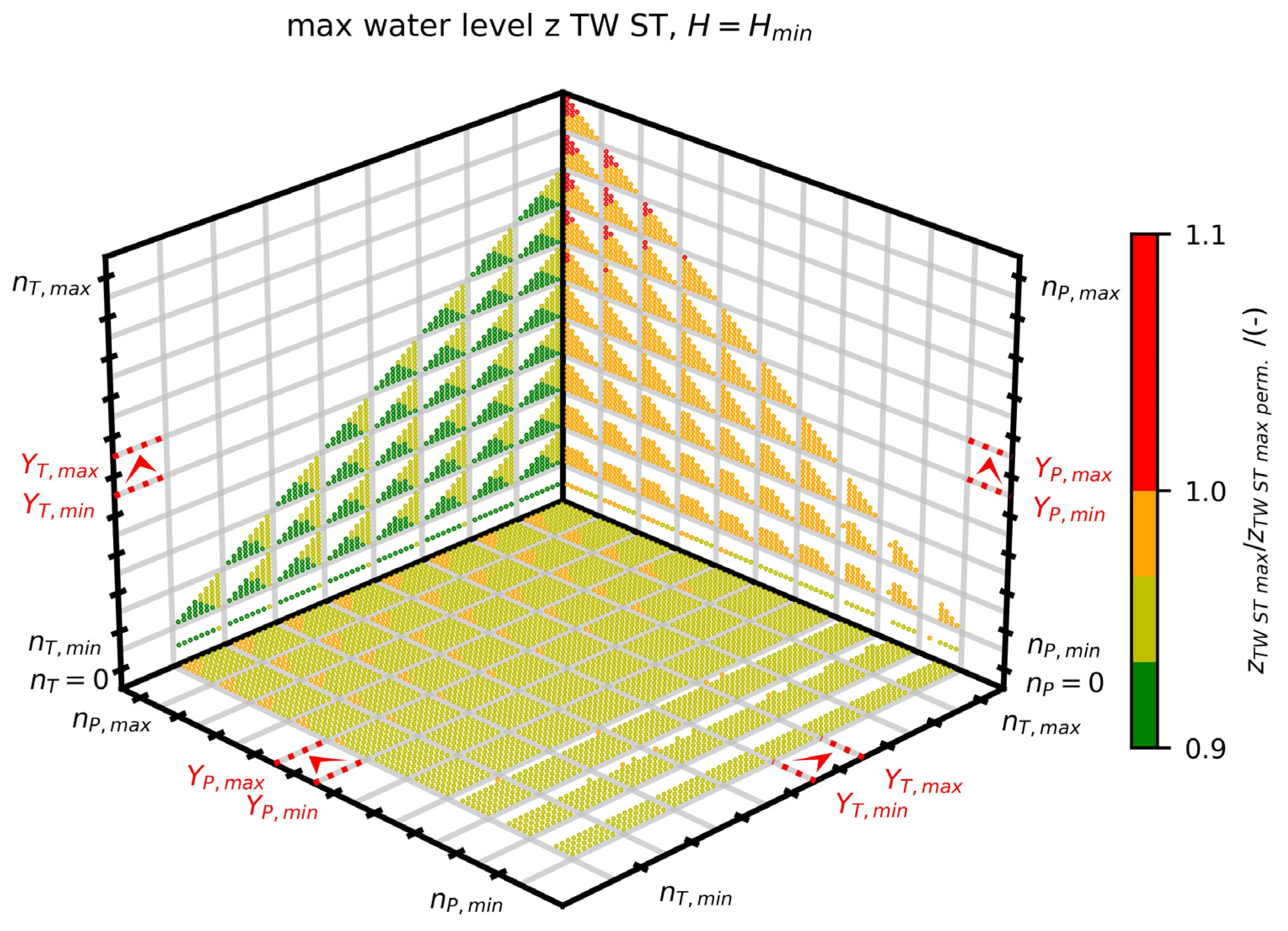
The maximum temporary pressure at the spiral case of both units remains below the maximum permitted one in all simulated cases. The minimum temporary pressure in the draft tube is above the permitted value in almost all simulations. The exception is shown in Figure 3a and Table 2 (dashed frame). For the extended plant operation conditions, the maximum water level in both surge tanks is within the permissible limits. However, there are conditions for pump operation mode with maximum rotational speed and maximum opening angle of the wicket gates where the upper limit of the water level in the tail water surge tank is exceeded (see Table 2 (dashed frame) and Figure 4). These combinations of machine conditions must be excluded during operation.
3.2.2. Asynchronous Emergency Shutdown
Besides the synchronous emergency shutdown, the asynchronous emergency shutdown is investigated. Experience at other hydro power plants [21] shows that certain unfortunate delays can result in a high dynamic load for the hydro power plant. Results of a measurement campaign of the Frades 2 model machine that is carried out in the meantime restricts the theoretically possible operation range. Thus, those operation transients are analysed for a subset of the extended operation range defined in Table 1. This leads to 81 start conditions for each hydraulic head.
All simulations start with a steady state condition followed by an asynchronous load rejection of both units from the electrical grid. Depending on the simulation case, the wicket gates or the spherical valves in front of the unit start to close at the time of load rejection of the corresponding unit as quick as possible according to the respective closing law. The emergency shutdown of unit 2 is delayed, the delay is adjustable and varied between 0 s and 30 s with a time step of 0.1 s.
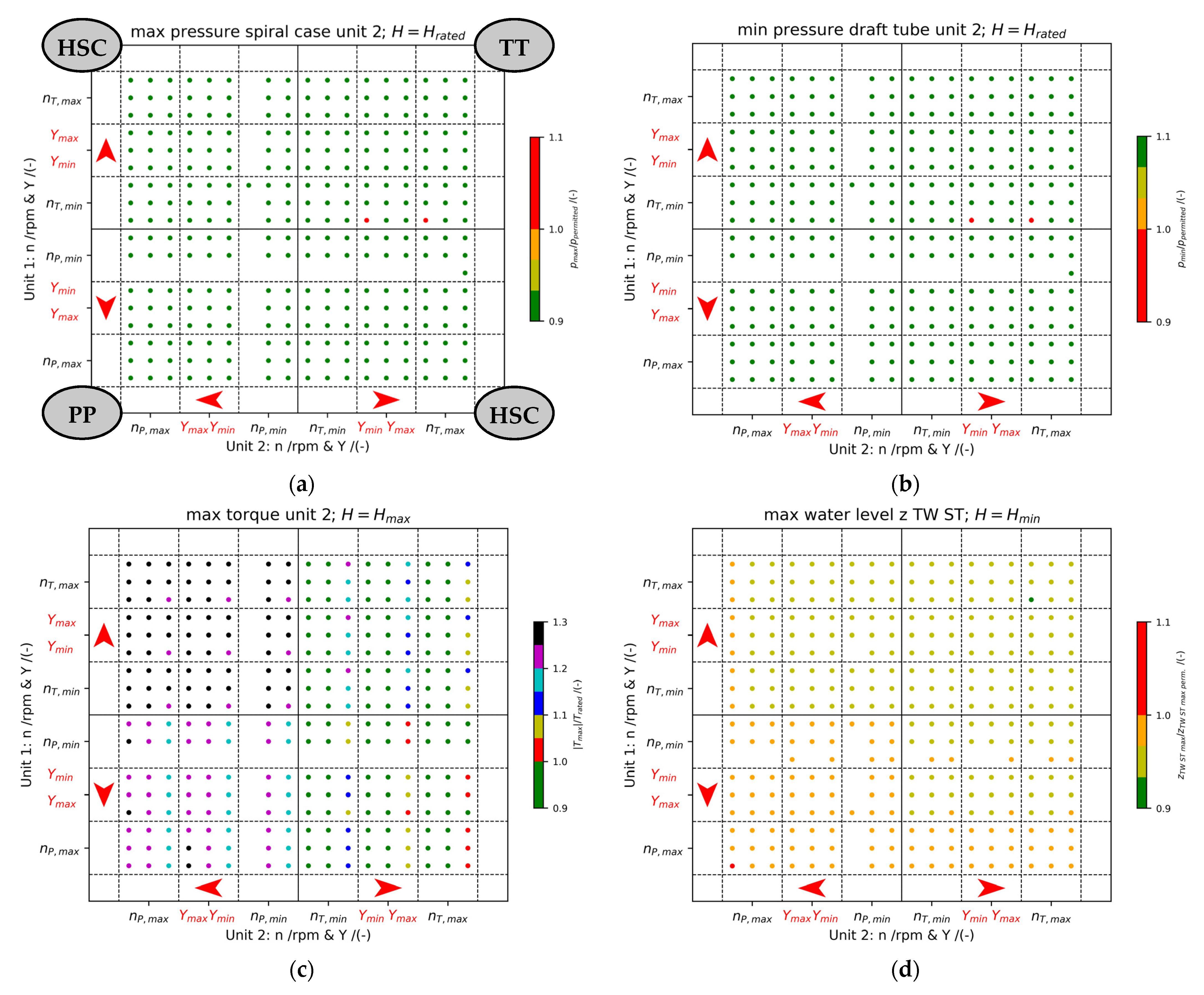
The structure of the result diagrams is similar to those already described for the synchronous emergency shutdown. Unit 1 is located on the y-axis, delayed unit 2 on the x-axis (Figure 5a). The diagram includes all possible start operating conditions of the hydro power plant (TT, PP, and HSC).
The results of all time-delayed simulations of the same start condition are reduced to one dot in the diagram presenting the largest extreme value of all simulations with the same start condition. A selection of the calculated extreme values is presented in Figure 5, and an overview of all calculated extreme values is tabulated in Table 3. The maximum temporary rotational speed |n|max of both units in the transient case remains below the permitted extreme value in all simulation cases.
The maximum observed temporary shaft torque |T|max occurs at asynchronous emergency shutdown with closing spherical valves at maximum head and is approximately 135% of the rated shaft torque, as shown in Figure 5c and Table 3 (dashed frame). This temporary occurring maximum extreme value is permitted for a short time according to an assessment by the OEM. Regarding the temporary observed pressure loads, the maximum temporary pressure at the spiral case pspiral case max of both units and the minimum temporary pressure in the draft tube pdraft tube min are located in the permitted range for all but two simulations (Figure 5a,b and Table 3 (dashed frame)). The temporary extreme pressure values of those simulations are outside the permitted range for the first time at a time delay of 19.6 s. In reality, such a time delay can be prevented by the plant control system. If one unit fails, the other one can be dropped within a few seconds and therefore this procedure avoids exceeding this limit.
For the current plant operation conditions, the maximum water level in both surge tanks (zHW ST max, zTW ST max) is within the permissible limits. However, there is one condition for pump operation mode with maximum rotational speed and maximum opening angle of the wicket gates where the upper limit of the water level in the tail water surge tank is minimally exceeded. This occurs at the tail water surge tank for the asynchronous emergency shutdown with closing spherical valves at minimum head (see Figure 5d and Table 3 (dashed frame)).
3.2.3. Additional Investigations concerning the HSC Mode
Operating the system in HSC mode results in new operation-related transient processes. This includes the start-up process of the hydro power plant to HSC mode and the loading of the units as well as the change between operating points from and to HSC mode. For each investigated head (Hrated, Hmax, Hmin) simulations are carried out for the largest permitted opening angle of the wicket gates Ymax and the maximum permitted rotational speed nmax. The analysis of the temporary occurring extreme values is similar to that of the previous simulations. The observed values remain within the permitted range. The temporary calculated shaft torques are below the simulation results of the synchronous and asynchronous emergency shutdowns. Regarding the results of the additional investigations concerning the HSC mode, no operational restrictions of the plant are observed.
4. Conclusions and Outlook
By using an extended operating range of both units and operating in HSC mode, a flexible power supply of the power plant Frades 2 is possible over a very wide power range. Due to the extensive investigation, some simulated extreme values emerged outside the permissible range for the extended operating range. These cases are assessed separately and the possible operating range of Frades 2 is adapted.
With the results of a laboratory measurement campaign of the Frades 2 model machine, the operating range of the hydro power plant Frades 2 is adjusted. The continuous and temporary permitted operating range identified by the measurement campaign includes the HSC mode and is examined in more detail.
The operating range where HSC operation is possible reveals large differences in the averaged efficiency of the machines. Higher normalized average machine efficiency is beneficial to reservoir water levels. Higher efficiency values are often associated with lower dynamic loads in the machines, meaning that less relative machine damage can be expected in return. The volumetric flow rate discharged from or to the headwater serves as a further measure for the specific choice of individual machine operation and can be compared with the expected relative damage of lower efficiency operation.
With the investigation results presented above, a significant increase in performance and flexibility of the hydro power plant Frades 2 is possible with this operating range. The safety of the existing plant for extended operation conditions is verified. Finally, the HSC mode will be investigated within a test campaign at the power plant.
Increasing the flexibility of hydro power plants are objectives that are also relevant for other existing hydro power plants and those in the planning stage. Since each hydro power plant is constructed differently due to the respective local conditions, with different types and numbers of units as well as a unique water-bearing system, the resultss obtained in this study cannot be transferred directly to other power plants. Furthermore, due to the uniqueness of the plants, it is not possible to make a general statement about HSC operation for the same operating range of each unit being more or less critical in case of plant transients compared to pure pump or turbine operation.
Therefore, in order to ensure safe operation of the plant with extended flexible operation modes, extensive investigation must be performed. This includes transient water hammer simulations of the entire plant including the waterways and all hydraulic components for all operational parameter combinations. In view of the results presented above, attention should definitely be paid to delayed emergency shutdowns. With flow field simulation, structural analysis, and model test campaigns, the flow effects and the structural load on the machines and the water-bearing components (e.g., pipes, valves, bifurcation…) have to be examined in more detail. The results obtained are used to draw conclusions about the power plant safety, the service life of the components, and the optimization of maintenance intervals. Finally, limitations in flexibility extension may result from these studies.
Author Contributions
Conceptualization, C.G. and S.R.; methodology, C.G. and S.R.; formal analysis, C.G. and S.R.; investigation, C.G.; writing—original draft preparation, C.G.; writing—review and editing, C.G. and S.R.; visualization, C.G.; supervision, S.R. All authors have read and agreed to the published version of the manuscript.
Funding
The Hydropower Extending Power System Flexibility (XFLEX HYDRO) project has received funding from the European Union’s Horizon 2020 research and innovation programme under grant agreement No. 857832. This publication was funded by the German Research Foundation (DFG) grant “Open Access Publication Funding/2023–2024/University of Stuttgart” (512689491).
Data Availability Statement
Basic data for the execution of this study were provided by Voith Hydro Holding GmbH & Co. KG. within the XFLEX HYDRO project. Restrictions apply to the availability of these data, due to confidentiality agreements. Therefore, the data are not publicly available.
Acknowledgments
The Hydropower Extending Power System Flexibility (XFLEX HYDRO) project has received funding from the European Union’s Horizon 2020 research and innovation programme under grant agreement No 857832. The authors would like to thank all XFLEX HYDRO project partners, especially EDP and Voith Hydro, for their support and cooperation. In addition, the authors would like to thank the German Research Foundation (DFG) for funding this publication.
Conflicts of Interest
The authors declare no conflict of interest.
References
- Nicolet, C.; Béguin, A.; Kawkabani, B.; Pannatier, Y.; Schwery, A.; Avellan, F. Variable Speed and Ternary Units to Mitigate Wind and Solar Intermittent Production. In Proceedings of the Hydrovision Conference 2014, Nashville, TN, USA, 22–25 July 2014; Session: Session 4H: Hydropower Systems and Flexibility. 2014. Available online: https://www.powervision-eng.ch/Profile/Publications/pdf/Hydrovision_2014.pdf (accessed on 28 May 2023).
- Hell, J. High flexible Hydropower Generation concepts for future grids. J. Phys. Conf. Ser. 2017, 813, 12007. [Google Scholar] [CrossRef] [Green Version]
- Valero, C.; Egusquiza, M.; Egusquiza, E.; Presas, A.; Valentin, D.; Bossio, M. Extension of Operating Range in Pump-Turbines. Influence of Head and Load. Energies 2017, 10, 2178. [Google Scholar] [CrossRef] [Green Version]
- Junginger, J.; Junginger, B.; Riedelbauch, S. Hydraulischer Kurzschluss im Kraftwerk Vianden—Anlagendynamik und CFD-Simulationen der Abzweiger. Wasserwirtsch 2019, 109, 48–51. [Google Scholar] [CrossRef]
- Alligné, S.; Béguin, A.; Biner, D.; Münch-Alligné, C.; Hasmatuchi, V.; Hugo, N.; Avellan, F.; Dujic, D.; Nicolet, C. Turbine mode start-up simulation of a FSFC variable speed pump-turbine prototype—Part I: 1D simulation. IOP Conf. Ser. Earth Environ. Sci. 2021, 774, 12052. [Google Scholar] [CrossRef]
- Nicolet, C.; Braun, O.; Ruchonnet, N.; Hell, J.; Béguin, A.; Avellan, F. Simulation of pump-turbine prototype fast mode transition for grid stability support. J. Phys. Conf. Ser. 2017, 813, 12040. [Google Scholar] [CrossRef] [Green Version]
- Schmid, J.; Alligné, S.; Biner, D.; Münch-Alligné, C.; Hugo, N.; Nicolet, C. Optimization of turbine start-up sequence of a full size frequency converter variable speed pump-turbine. IOP Conf. Ser. Earth Environ. Sci. 2022, 1079, 12109. [Google Scholar] [CrossRef]
- Khalfaoui, K.; Tismer, A.; Riedelbauch, S. Numerical investigation of the structural behaviour of a headwater bifurcation in hydraulic short circuit. IOP Conf. Ser. Earth Environ. Sci. 2022, 1079, 12078. [Google Scholar] [CrossRef]
- Decaix, J.; Drommi, J.-L.; Avellan, F.; Münch-Alligné, C. CFD simulations of hydraulic short-circuits in junctions, application to the Grand’Maison power plant. IOP Conf. Ser. Earth Environ. Sci. 2022, 1079, 12106. [Google Scholar] [CrossRef]
- Wack, J.; Grübel, M.; Conrad, P.; von Locquenghien, F.; Jester-Zürker, R.; Riedelbauch, S. Numerical investigation of the impact of cavitation on the pressure fluctuations in a Francis turbine at deep part load conditions. IOP Conf. Ser. Earth Environ. Sci. 2022, 1079, 12044. [Google Scholar] [CrossRef]
- Biner, D.; Alligné, S.; Hasmatuchi, V.; Nicolet, C.; Hugo, N.; Avellan, F.; Dujic, D.; Münch-Alligné, C. Turbine mode start-up simulation of a variable speed Francis pump-turbine prototype—Part II: 3-D unsteady CFD and FEM. IOP Conf. Ser. Earth Environ. Sci. 2021, 774, 12070. [Google Scholar] [CrossRef]
- Stens, C. Investigation of a Fast Transition from Pump Mode to Generating Mode in a Reversible Pump Turbine; Institut für Strömungsmechanik und Hydraulische Strömungsmaschinen: Stuttgart, Germany, 2018; ISBN 978-3-9812054-5-9. [Google Scholar]
- Yin, C.; Yang, J.; Zeng, W.; Cheng, Y. Simulation of the simultaneous load rejection processes of two parallel pump turbines using a 1D–3D approach. IOP Conf. Ser. Earth Environ. Sci. 2019, 240, 82001. [Google Scholar] [CrossRef]
- Weber, W.; von Locquenghien, F.; Conrad, P.; Koutnik, J. Dynamic stresses in a Francis model turbine at deep part load. J. Phys. Conf. Ser. 2017, 813, 12014. [Google Scholar] [CrossRef] [Green Version]
- Seidel, U.; Mende, C.; Hübner, B.; Weber, W.; Otto, A. Dynamic loads in Francis runners and their impact on fatigue life. IOP Conf. Ser. Earth Environ. Sci. 2014, 22, 32054. [Google Scholar] [CrossRef] [Green Version]
- XFLEX Hydro. Official Webpage. Available online: https://www.xflexhydro.com/ (accessed on 9 May 2023).
- Koutnik, J. Frades II—Variable speed pumped storage project and its benefit to the electrical grid. In Proceedings of the Renewable Energy World Conference & Exhibition North America, Orlando, FL, USA, 10–12 December 2012. [Google Scholar] [CrossRef]
- Koutnik, J.; Hildinger, T.; Bruns, M. A Step forward—Variable Speed Pumped Storage Power Plant Frades II. Wasserwirtschaft 2015, 105, 27–32. [Google Scholar] [CrossRef]
- Harbort, T. Entwicklung eines Echtzeitfähigen Simulationsprogrammes zur Untersuchung Instationärer Vorgänge in Wasserkraftwerken; Institut für Strömungsmechanik und Hydraulische Strömungsmaschinen: Stuttgart, Germany, 1999; ISBN 3-9804376-4-7. [Google Scholar]
- Chaudhry, M.H. Applied Hydraulic Transients; Springer: New York, NY, USA, 2014; ISBN 978-1-4614-8537-7. [Google Scholar]
- Fang, Y.J.; Koutnik, J. The numerical simulation of the delayed load rejection of a pump-turbine powerplant. IOP Conf. Ser. Earth Environ. Sci. 2012, 15, 22018. [Google Scholar] [CrossRef]
Figure 1.
Simulation model of pumped-storage plant Frades 2.

Figure 2.
(a) Current operating range Frades 2; (b–d) current and extended operating range Frades 2; normalized average machine efficiency and power plant net volumetric flow; H = Hrated.
Figure 2.
(a) Current operating range Frades 2; (b–d) current and extended operating range Frades 2; normalized average machine efficiency and power plant net volumetric flow; H = Hrated.

Figure 3.
(a) Minimum pressure draft tube unit 1 and (b) maximum shaft torque unit 1, synchronous emergency shutdown with closing spherical valves, H = Hmax.
Figure 3.
(a) Minimum pressure draft tube unit 1 and (b) maximum shaft torque unit 1, synchronous emergency shutdown with closing spherical valves, H = Hmax.

Figure 4.
Maximum water level tail water surge tank, synchronous emergency shutdown with closing spherical valves, H = Hmin.
Figure 4.
Maximum water level tail water surge tank, synchronous emergency shutdown with closing spherical valves, H = Hmin.

Figure 5.
Extreme values for asynchronous emergency shutdown with closing spherical valves: (a) maximum pressure spiral case unit 1 (H = Hrated); (b) minimum pressure draft tube unit 2 (H = Hrated); (c) maximum torque unit 2 (H = Hmax); (d) maximum water level tail water surge tank (H = Hmin).
Figure 5.
Extreme values for asynchronous emergency shutdown with closing spherical valves: (a) maximum pressure spiral case unit 1 (H = Hrated); (b) minimum pressure draft tube unit 2 (H = Hrated); (c) maximum torque unit 2 (H = Hmax); (d) maximum water level tail water surge tank (H = Hmin).


Table 1.
Input parameter matrix of existing and extended plant operation.
| HWL | TWL | n1 | n2 | Y1 | Y2 | ||||
|---|---|---|---|---|---|---|---|---|---|
| (m.a.s.l.) * | (m.a.s.l.) * | (min−1) | (min−1) | (-)/(°) | (-)/(°) | ||||
| 690.80 | 270.36 | 350.0 | 350.0 | 0.12/2.93 | 0.12/2.93 | ||||
| 685.80 | 265.36 | … (6) ** … | … (6) ** … | … (5) ** … | … (5) ** … | ||||
| 684.00 | 259.00 | 371.4 | 371.4 | 0.87/21.14 | 0.87/21.14 | ||||
| Legend: | 356.3 | 356.3 | 0.44/10.75 | 0.44/10.75 | |||||
| Turbine Mode | Pump Mode | … (8) ** … | … (8) ** … | … (5) ** … | … (5) ** … | ||||
| 381.2 | 381.2 | 1.04/25.26 | 1.04/25.26 | ||||||
* elevation: meters above sea level; ** number of covered values between minimum and maximum values.
Table 2.
Simulated temporary extreme values in case of synchronous emergency shutdown with closing wicket gates and synchronous emergency shutdown with closing spherical valves for different heads.
Table 2.
Simulated temporary extreme values in case of synchronous emergency shutdown with closing wicket gates and synchronous emergency shutdown with closing spherical valves for different heads.
| Synchronous Emergency Shutdown with Closing Wicket Gates | Synchronous Emergency Shutdown with Closing Spherical Valves | ||||||
|---|---|---|---|---|---|---|---|
| Extreme Values * | Hrated | Hmax | Hmin | Hrated | Hmax | Hmin | |
| |n1|max | (-) | 0.94 | 0.95 | 0.93 | 0.96 | 0.97 | 0.95 |
| |n2|max | (-) | 0.94 | 0.95 | 0.93 | 0.96 | 0.97 | 0.95 |
| |T1|max ** | (-) | 1.26 | 1.30 | 1.24 | 1.26 | 1.30 | 1.24 |
| |T2|max ** | (-) | 1.14 | 1.18 | 1.12 | 1.16 | 1.20 | 1.13 |
| p1 spiral case max | (-) | 0.95 | 0.96 | 0.94 | 0.88 | 0.89 | 0.88 |
| p2 spiral case max | (-) | 0.95 | 0.96 | 0.95 | 0.88 | 0.89 | 0.88 |
| p1 draft tube min | (-) | 3.51 | 3.00 | 3.30 | 2.14 | 0.41 | 4.29 |
| p2 draft tube min | (-) | 3.21 | 2.31 | 3.83 | 3.92 | 2.44 | 4.34 |
| zHW ST max | (-) | 0.99 | 0.99 | 0.98 | 0.99 | 1.00 | 0.99 |
| zHW ST min | (-) | 1.03 | 1.04 | 1.03 | 1.02 | 1.03 | 1.02 |
| zTW ST max | (-) | 0.98 | 0.96 | 0.99 | 0.99 | 0.98 | 1.00 |
| zTW ST min | (-) | 1.19 | 1.16 | 1.21 | 1.16 | 1.13 | 1.19 |
* Normalised with the temp. permitted extreme values in transient conditions; ** normalised with the rated shaft torque.
Table 3.
Simulated temporary extreme values in case of asynchronous emergency shutdown with closing wicket gates and asynchronous emergency shutdown with closing spherical valves for different heads.
Table 3.
Simulated temporary extreme values in case of asynchronous emergency shutdown with closing wicket gates and asynchronous emergency shutdown with closing spherical valves for different heads.
| Asynchronous Emergency Shutdown with Closing Wicket Gates | Asynchronous Emergency Shutdown with Closing Spherical Valves | ||||||
|---|---|---|---|---|---|---|---|
| Extreme Values * | Hrated | Hmax | Hmin | Hrated | Hmax | Hmin | |
| |n1|max | (-) | 0.96 | 0.96 | 0.94 | 0.97 | 0.97 | 0.96 |
| |n2|max | (-) | 0.97 | 0.97 | 0.96 | 0.98 | 0.98 | 0.97 |
| |T1|max ** | (-) | 1.20 | 1.24 | 1.18 | 1.31 | 1.34 | 1.28 |
| |T2|max ** | (-) | 1.27 | 1.26 | 1.22 | 1.31 | 1.35 | 1.28 |
| p1 spiral case max | (-) | 0.95 | 0.96 | 0.95 | 0.89 | 0.91 | 0.88 |
| p2 spiral case max | (-) | 0.95 | 0.96 | 0.95 | 1.03 | 0.90 | 0.97 |
| p1 draft tube min | (-) | 2.64 | 2.85 | 4.20 | 2.63 | 3.21 | 4.40 |
| p2 draft tube min | (-) | 2.62 | 2.22 | 3.62 | 0.44 | 2.85 | 2.67 |
| zHW ST max | (-) | 0.99 | 0.99 | 0.98 | 0.99 | 1.00 | 0.99 |
| zHW ST min | (-) | 1.03 | 1.04 | 1.03 | 1.02 | 1.03 | 1.02 |
| zTW ST max | (-) | 0.97 | 0.95 | 0.99 | 0.99 | 0.98 | 1.00 |
| zTW ST min | (-) | 1.20 | 1.17 | 1.22 | 1.17 | 1.13 | 1.19 |
* Normalised with the temp. permitted extreme values in transient conditions; ** normalised with the rated shaft torque.
Disclaimer/Publisher’s Note: The statements, opinions and data contained in all publications are solely those of the individual author(s) and contributor(s) and not of MDPI and/or the editor(s). MDPI and/or the editor(s) disclaim responsibility for any injury to people or property resulting from any ideas, methods, instructions or products referred to in the content. |
© 2023 by the authors. Licensee MDPI, Basel, Switzerland. This article is an open access article distributed under the terms and conditions of the Creative Commons Attribution (CC BY) license (https://creativecommons.org/licenses/by/4.0/).
Share and Cite
MDPI and ACS Style
Geiger, C.; Riedelbauch, S. Power Plant Transients including Hydraulic Short Circuit Operation Mode. Energies 2023, 16, 4492. https://doi.org/10.3390/en16114492
AMA Style
Geiger C, Riedelbauch S. Power Plant Transients including Hydraulic Short Circuit Operation Mode. Energies. 2023; 16(11):4492. https://doi.org/10.3390/en16114492
Chicago/Turabian StyleGeiger, Christoph, and Stefan Riedelbauch. 2023. "Power Plant Transients including Hydraulic Short Circuit Operation Mode" Energies 16, no. 11: 4492. https://doi.org/10.3390/en16114492
Note that from the first issue of 2016, this journal uses article numbers instead of page numbers. See further details here.