Brazilian Test for Tensile Failure of Anisotropic Shale under Different Strain Rates at Quasi-static Loading

1
Beijing Key Laboratory of Urban Underground Space Engineering, Department of Civil Engineering, School of Civil & Resource Engineering, University of Science & Technology Beijing, Beijing 100083, China
2
Key Laboratory of Shale Gas and Geoengineering, Institute of Geology and Geophysics, Chinese Academy of Sciences, Beijing 100029,China
*
Author to whom correspondence should be addressed.
Energies 2017, 10(9), 1324; https://doi.org/10.3390/en10091324
Submission received: 19 July 2017
/
Revised: 23 August 2017
/
Accepted: 30 August 2017
/
Published: 2 September 2017
(This article belongs to the Special Issue Flow and Transport Properties of Unconventional Reservoirs)
Abstract
:Shale formations show obvious anisotropic characteristics in their mechanical properties due to pronounced bedding planes and natural fractures. This anisotropic behavior generally creates complex fracturing networks and is crucial to gas shale stimulation. Although much research has been done to study the anisotropic compression behaviors of shale with static and quasi-static strain rates, there are limited investigations addressing the anisotropic tensile behaviors of shale at quasi-static strain rate. In this work, the anisotropic tensile behaviors of Longmaxi shales were studied systematically at different strain rates from 10−5 to 10−2 s−1 by performing Brazilian splitting tests. Testing results reveal the tensile strength anisotropy, rate dependency, and the stimulated fracture pattern morphology. The results show that the orientation between the applied force and bedding direction has an obvious effect on the tensile strength and fracture pattern. The rate dependency of shale under different loading rates is different for shale samples with various orientations. It was suggested that a complex tensile fracture pattern can be easily formed when using a high loading rate. The result sheds light on how to stimulate a complex fracturing network during field hydraulic fracturing treatment.
1. Introduction
Characterization of anisotropy is critical in shale due to the grain alignments and the developed natural fractures. Platy minerals such as clays have a tendency to be aligned in a parallel orientation, and form geologic discontinuities. These geologic discontinuities have a major influence on the mechanical behaviors in the oil-gas field, including hydraulic fracturing, borehole stability assessment, evaluation of stable mud weight windows for rock drilling, as well as other rock engineering problems [1,2]. The tensile strength of shale can be strongly affected by the bedding planes, which often results in anisotropy. Although in fact it is a standard approximation for several applications that the tensile strength of shale is zero [3]. However, as reported by many scholars [4,5,6], the role of tensile strength on hydraulic fracturing is evident, which relates to the formation of a complex fracture network in shale formation. Many efforts have been taken to investigate the tensile behaviors of shale currently, but few systematic reports exist on the dynamic tensile failure characteristics for shale.
The anisotropic tensile failure characteristics of shale have been studied recently. Mokhtari et al. [5] conducted tensile testing to study the failure behaviors of Mancos and Green River shales and grasped the fracture growth patterns. Hou et al. [7] studied the anisotropic characteristics of the tensile strength and failure mode of black shale from the Longmaxi Formation using Brazilian tests. The evolution of absorbed energy during sample deformation was also analyzed using acoustic emission (AE) monitoring, and the loading rate was kept at 0.01 mm/min untial failure of the sample. Fatahi [8] used numerical simulation to study the direct tensile properties of western US shale. The numerical tests considered two cases, the tensile loading parallel and perpendicular to the bedding plane. They found that when the applied loading was perpendicular to the bedding plane, the sample fails from the rich shale layer, and the sample has lower tensile strength. Chong et al. [9] used a method called the DEM-AE model based on moment tensor analysis to study the anisotropic AE characteristics of the shale material. The result shows that for different anisotropy angles, a linear logarithmic relationship existed between the cumulative AE events and the seismic magnitude. For the tensile strength testing conducted above, almost all the tests are under static loading rate (i.e., loading strain rate is at ~10−5 magnitude). Mechanical properties of shale under dynamic tension are rarely studied. However, shale sample behaviors under dynamic tension may be different from those under static loading conditions, not only for peak strength, but also for the fracture propagation path, and the formation of complex fracturing network. Discontinuities play a critical role in creating a complex fracture network, and the influence of dynamic tension on the evolution of the fracturing network, which should be deeply investigated. Among the published literature, the Brazilian test [10,11], flattened Brazilian disc tests [12,13,14,15,16], Semicircular bending (SCB) test [17], and the split Hopkinson pressure bar (SHPB) tests [18,19,20,21] were mainly adopted to research the mechanical properties of rock material under dynamic tension. It was found that the strength of rock presented rate dependency; rock strength increases with the increase of strain rate, and almost all the studies are focused on dolerite [22], limestone [10], granite [17,19], tuff [21], sandstone [23], and basalt [21].
The Brazilian test method, due to its simple sample preparation and experimental procedures, is a popular method used to obtain the tensile strength of rocklike and rock material [17,23]. In this work, a series of indirect dynamic tension tests for shale samples with inclinations of 0°, 30°, 60°, and 90° at different strain rates of 10−5–10−2 s−1 was performed to investigate the rate dependency, the fracture network propagation, and the interactions between bedding planes and fractures. The effects of strain rate on the strength and failure characteristics for anisotropic Longmaxi shale have been documented first.
2. Experimental Methods
2.1. Materials and Sample Preparation
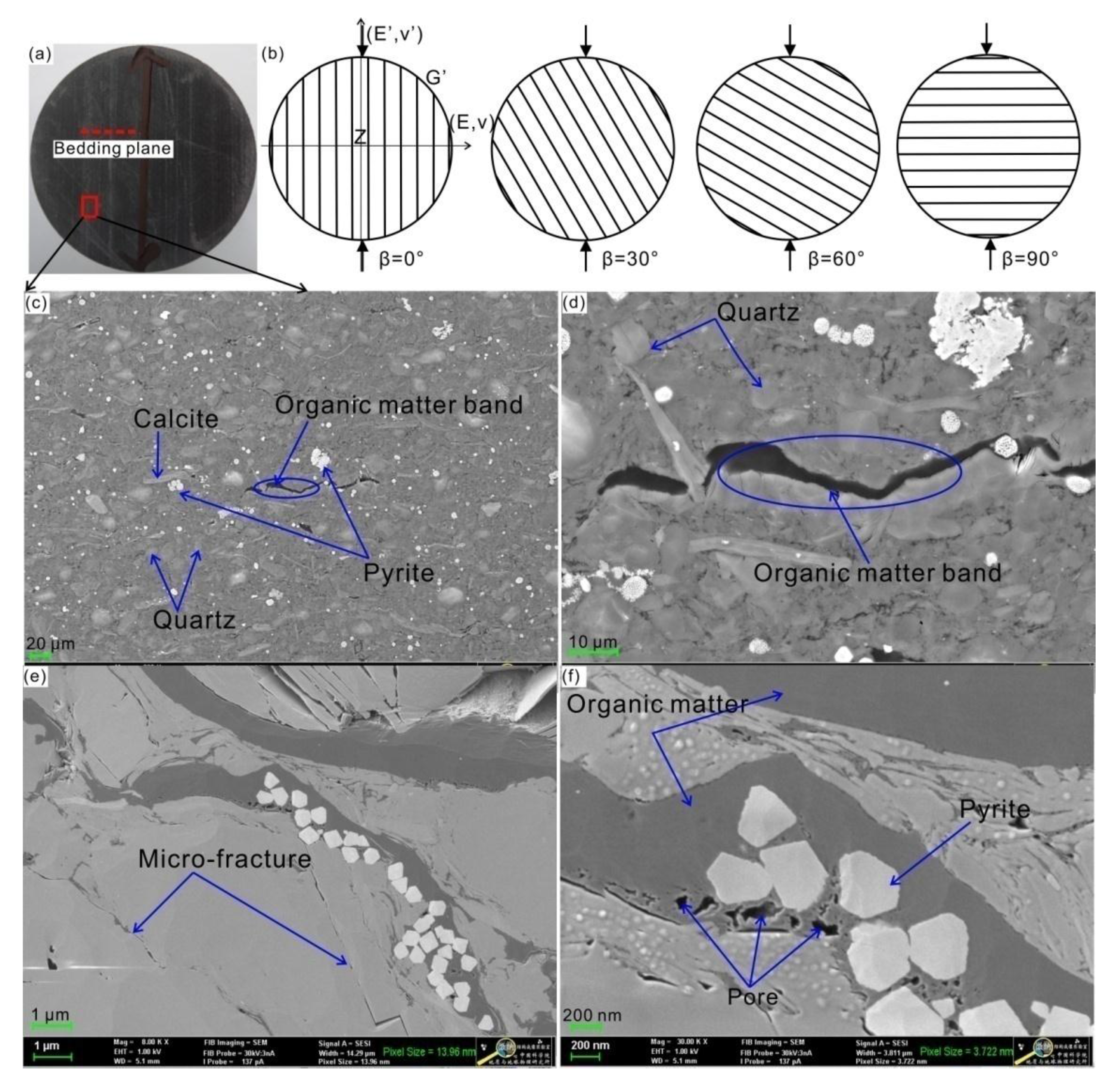
The shale was from the Longmaxi formation in the Lower Silurian located in Shizhu County Chongqing, China. The cores, obtained from a depth of 20 m underground with alternating thin and thick layers (Figure 1a), represent a carbonate rich, mature gas shale. The average bulk density of the shale samples is 2.62 g/cm3. The tensile behavior was studied at four orientations on shale core samples drilled parallel to the bedding plane, and each cylindrical sample was polished having a diameter of 50 mm, and a thickness of 25 mm for the Brazilian test. The tolerance of planeness and cylinder perpendicularity of the tested samples met the standards of the International Society for Rock Mechanics (ISRM) Suggested Method [24]. The sample was loaded at different orientations, and the intersection angle between the bedding plane and loading direction was 0°, 30°, 60°, and 90°, respectively, as shown in Figure 1b. We also measured the porosity by mercury porosimetry testing, and it was about 2.2%–7.5%. By using scanning electronic microscopy (SEM, Zeiss Company, Oberkochen, Germany) imaging analysis, distinct bedding organic matter with sub-parallel oriented pyrite flakes and calcareous bands in the transverse isotropic shale samples can be observed, as shown in Figure 1c,d.
2.2. Experimental Apparatus
The Brazilian splitting tests were performed at a servo-hydraulically controlled deformation apparatus (GCTS RTR-2000, GCTS Company, Phoenix, AZ, USA). The maximum axial force is 4600 kN, and the dynamic frequency of the machine is 0–10 Hz. During the tests, the axial loading was carried out under displacement control mode with a loading rate of 0.24 mm/min, 1.2 mm/min, 6 mm/min, and 30 mm/min, respectively. Therefore, the dynamic Brazilian test for shale sample at strain rates ranging from 8 × 10⁻⁵ s−1, 4 × 10⁻⁴ s−1, 2 × 10⁻⁴ s−1, to 1 × 10⁻² s−1, respectively. The applied force and loading displacement can be recorded simultaneously at the same sampling frequency during the whole deformation process. During the experiments, the disc shale sample was placed on a specially designed splitting clamp, the clamp can ensure a point contact mode when applying loading to the shale samples.
2.3. Anisotropic Brazilian Test
During sample deformation, to create a tensile fracture, it should overcome the tensile strength of rock and in-situ stress. When bedding plane and natural fractures are present, the tensile strength is typically a function of orientation. To study the anisotropy in tensile behavior, the splitting test also known as the Brazilian test or diametrical compression test was applied. The Brazilian test is an ISRM recommended method for measurement of the tensile strength of rocks (ISRM 1978), it is an easy and common method for determining the tensile strength of rock. Tensile strength is calculated in this test by using an equation, which assumes isotropic material properties, as shown in Equation (1). The principal tensile stress, in particular at the rock disc center where a crack initiates, should be known when using Equation (1) to obtain the tensile strength of rock samples. The expression is as below:
where P is the applied loading; D is the diameter of disc sample, D = 2R; t is the thickness of the sample.
Equation (1) is suitable for isotropic rock material, which was deduced based on the elasticity theory. From the expression, it shows the tensile stress distribution at the center of the disc sample, that is perpendicular to the loaded diameter when the sample fails [25]. Fracture initiates from the center of the sample and propagates outward along the loading direction [26]. Due to the differential stress distribution in anisotropic rock samples compared to the isotropic ones, it is erroneous when using Equation (1) to calculate the tensile strength for anisotropic rock. To resolve this problem, Claesson and Bohloli [27] proposed a new, reasonably accurate analytical solution to calculate the tensile strength for anisotropic rocks and verified its accuracy, it is expressed as below:
where P is the applied force, θ is the intersection angle between axial force and bedding plane, D is the diameter of the sample, t is sample thickness, E is the elastic modulus in the transverse isotropic plane, E’ and G’ are the elasticity modulus and shear modulus for the plane perpendicular to the transverse isotropic plane, v’ is the Poisson’s ratio in the transverse isotropic plane.
3. Experimental Results
3.1. Determination of Elastic Parameters
Using Equation (2) to calculate the tensile strength, we should determine the five elastic parameters for the transverse isotropic disc shale sample. Generally, three samples with inclinations of 0°, 45°, and 90° are needed to obtain these parameters (E, E’, v, v’, G’). In order to facilitate the sample preparation and ensure the testing precision, the Saint–Venant empirical formula was used to calculate the shear modulus, G’, as below [28]:
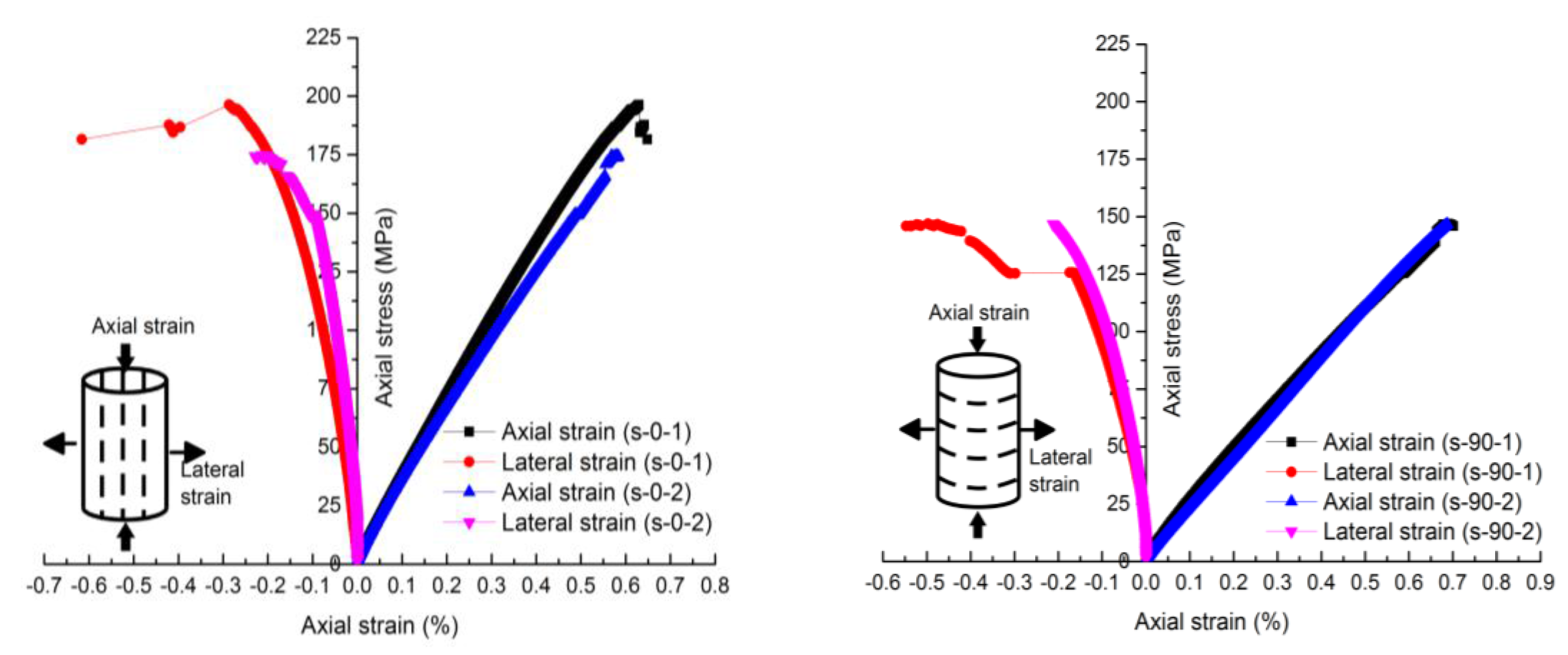
As a result, we only need to conduct unconfined (uniaxial) compressive strength tests for shale samples parallel and perpendicular to bedding planes. Typical stress-strain curves for cylinder shaped shale sample (50 mm diameter × 100 mm height) are shown in Figure 2. During the uniaxial compressive test, axial loading was carried out under strain control with loading rate of 0.06 mm/min (strain rate is 1.0 × 10⁻⁵ s−1). We can further calculate the elastic parameters from the stress strain relationships, as listed in Table 1. Chong and Boresi [29] have showed that shale has strain rate dependence on Young’s modulus and no dependence on Poission’s ratio. However, in this work, we assume that those two elastic parameters are constant when using Equation (2) to calculate the tensile strength.
3.2. Tensile Strength of Anisotropic Shale
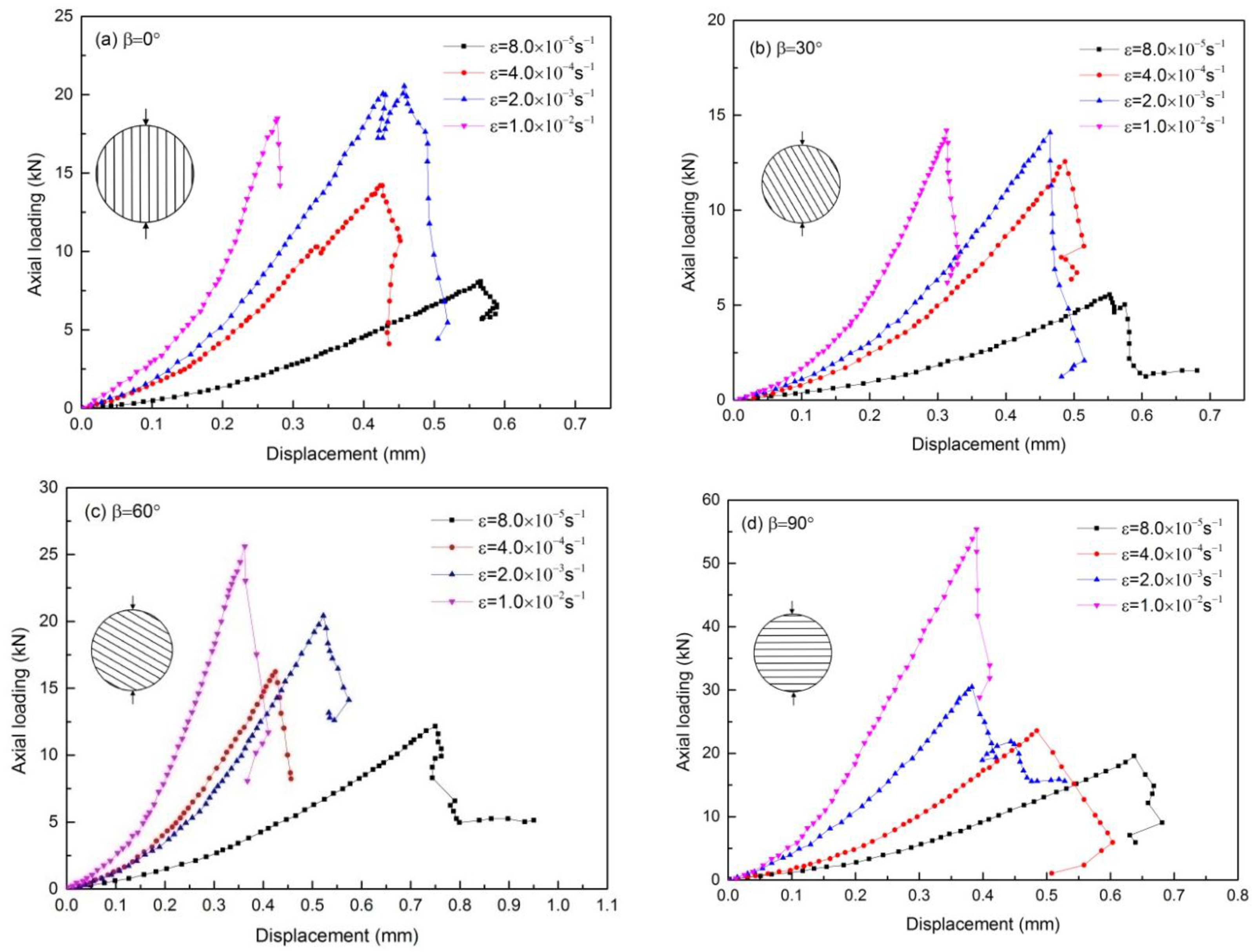
Under different loading rates, the relationship between axial loading and displacement are shown in Figure 3. The peak loading for the shale samples changes with orientation and strain rate. This indicates the anisotropy of tensile characteristics, and the tensile strength of shale exhibits rate dependency.
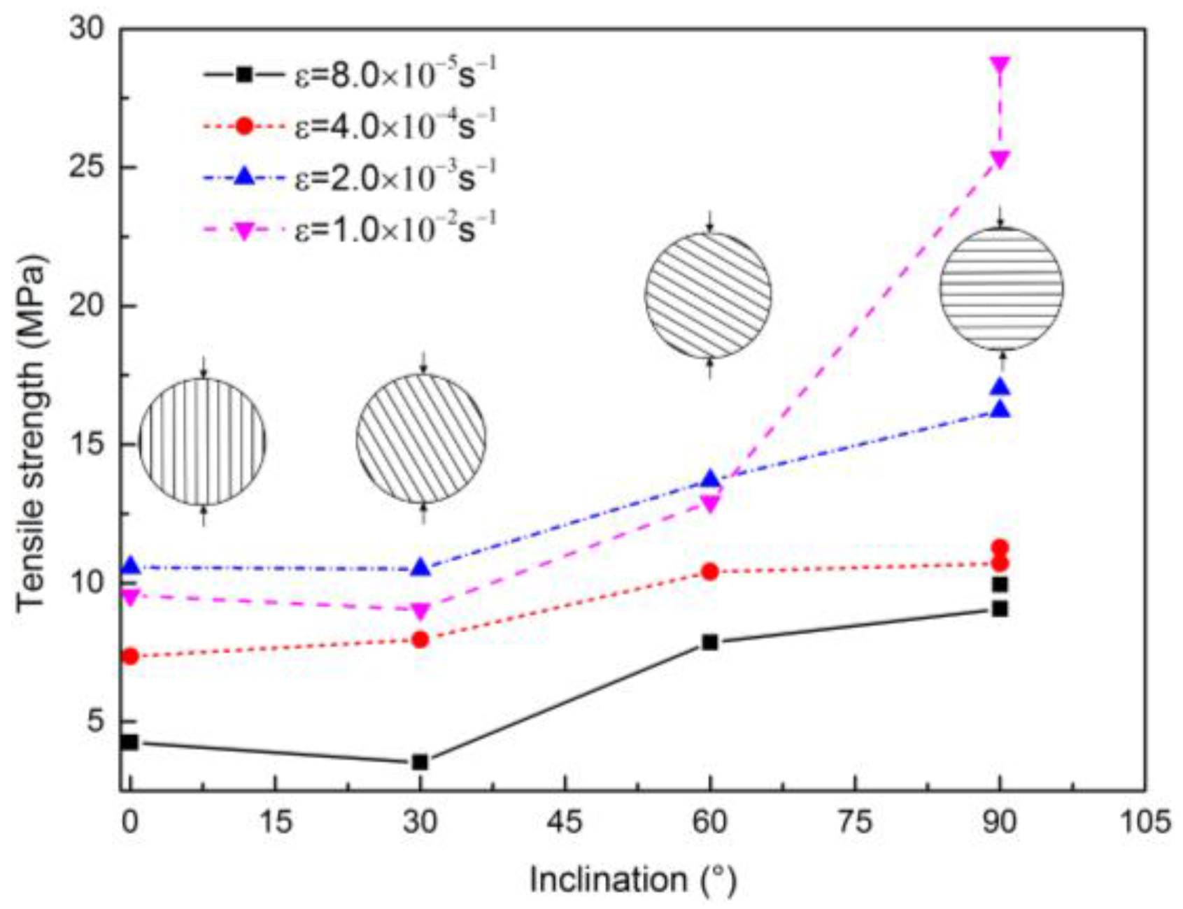
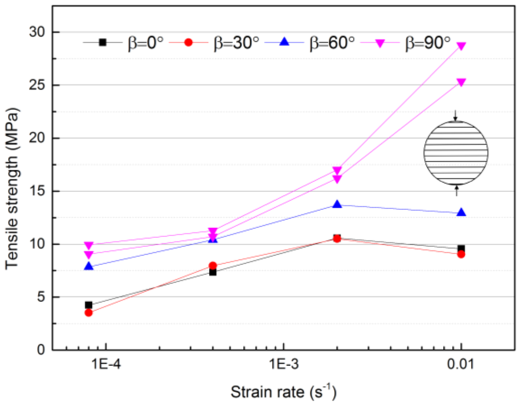
Using Equation (2), the dynamic tensile strength of the shale sample was calculated, as listed in Table 2. At the same time, we also obtained the tensile strength using Equation (1). When using Equation (1) to calculate the tensile strength, the structural anisotropy of shale is not considered, and the results are different from the results from Equation (2). From Table 2, it can be seen that the error of the results using Equations (1) and (2) is variable and not constant, the error depends on the structural and elastic parameters of the anisotropic shale, this implies that it is reasonable when using Equation (2) to obtain the tensile strength of shale. Figure 4 plots the result of the tensile strength against the bedding plane orientation. The tension strength of shale with 90° orientation is always the maximum. From Figure 5, we can see that rate dependency for the splitting tensile strength of the shale samples exists. For shale samples with a certain orientation, peak strength changes with the increase of strain rate. It can be seen that tensile strength increases monotonically with increasing strain rate for the samples with 90° orientation. However, for samples with orientation of 0°, 30°, and 60°, tensile strength increases until a strain rate of 1 × 10⁻³ s−1, and then decreases as strain rate continues to increase. These results indicate that the bedding plane properties have a crucial influence on the tensile strength of shale. It implies that the bedding plane controls the peak tensile stress and the fracture propagation path. When the strain rate is the largest, due to the weak cement of bedding plane, it cannot resist deformation when loading force acts on the samples. Therefore, the tensile strength decreases instead of increasing strain rate exceeds 1 × 10⁻³ s−1 for the tested samples. This result is different from the relative homogenous rock or rock-like materials, such as granite, tuff, sandstone and limestone; the tensile strength almost presents a linear increase with the increase of measured strain rate [10,11,13]. From the test result, there may be a boundary of positive rate dependence between 60° and 90°, and we may determine the actual boundary of inclination by performing more additional experiments.
3.3. Fracture Pattern Analysis
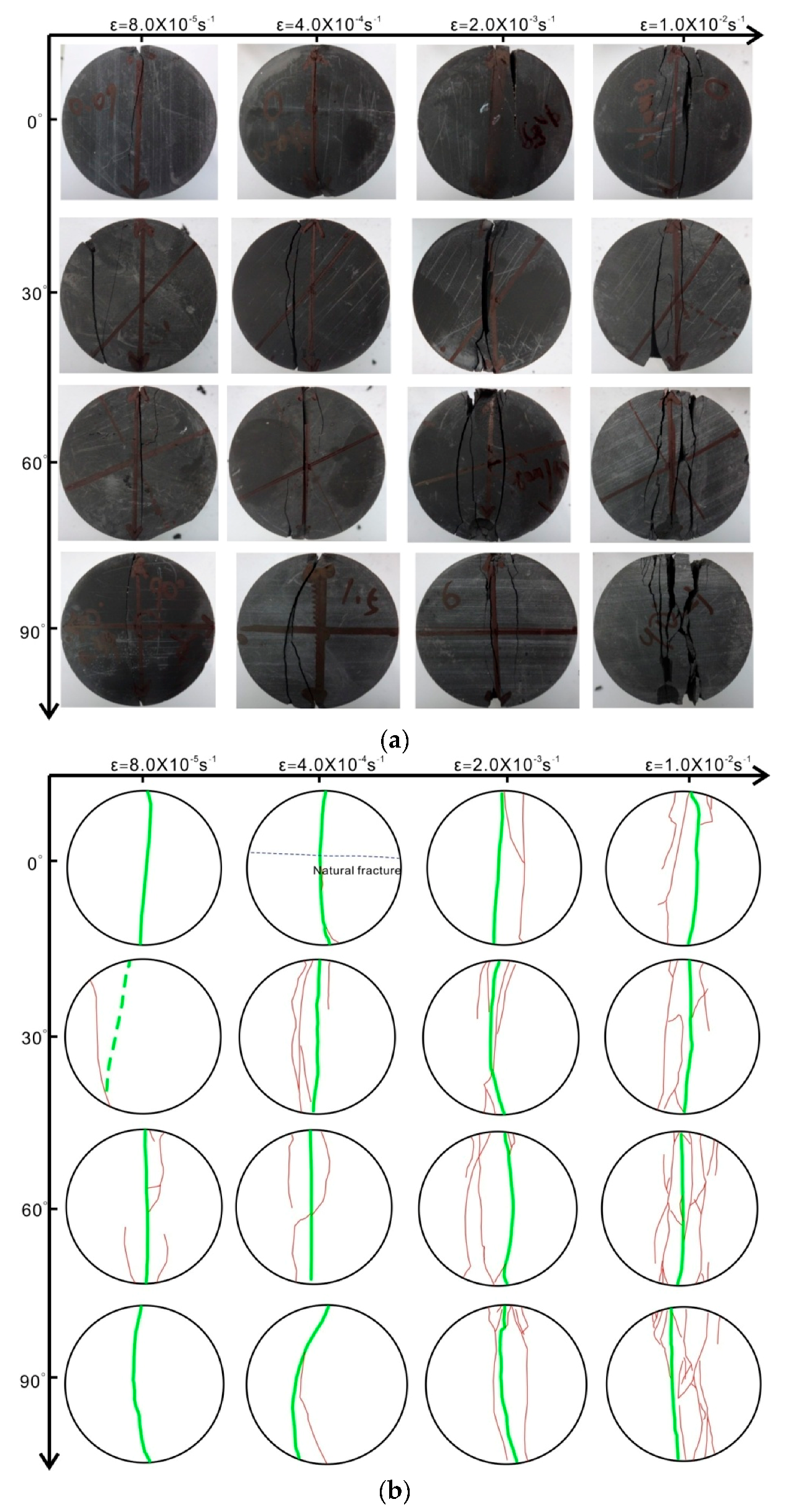
Figure 6 plots the fracture morphology of shale samples with orientations of 0°, 30°, 60°, and 90°, under different strain rates. In order to clearly present the fracture pattern after each test, we extract the fractures on one side of the samples. We can see that fracture network complexity increases with the increase of strain rate. Under a low strain rate of 8 × 10⁻⁵ s−1, a single crack can be observed; however, under a high strain rate of 1 × 10⁻² s−1, multiple cracks appear and a complex fracturing network forms. In addition, the orientation of the bedding plane also has an obvious influence on the fracture propagation path and fracturing network morphology. For samples under a strain rate of 8 × 10⁻⁵ s−1, sample with a 0° orientation, a central crack occurs along the bedding plane with the least applied axial loading among the samples; sample with 30° orientation, because of the existing natural fractures, cracks first initiate here, and there is some shearing for samples under strain rates of 2× 10⁻⁴ s−1, 1 × 10⁻³ s−1, and 1 × 10⁻² s−1, higher degree of fracture deviation towards the bedding plane occurs; at 60° orientation, fracture deviates the bedding plane to a large extend; at 90° orientation, non-central fractures are created. It should be noted that due to the local heterogeneities and existence of natural fractures, the fracture pattern observed from one side might not reflect the spatial pattern of the fracturing network in shale samples well.
For sample with 0° orientation, fracture propagates along the bedding plane; this indicates that the tensile strength is influenced by the layers instead of the shale matrix; for shale sample with this kind of structure, pure tensile failure occurs. For the sample with 30° orientation, shear slippage easily occurs along the bedding plane, and a mixture of shear and tensile failure co-exists. Therefore, when the orientation between the loading direction and bedding plane ranges 0–30°, the layers are easily stimulated. It analogues to the case that the critical angle between hydraulic fracture and natural fracture for stimulation of natural fractures. For the sample with a 90° orientation, the fracture propagates across the rock matrix and bedding plane, tensile failure occurs, and the shale matrix controls the tensile strength. Moreover, as the loading rate grows, the number and scale of fractures increase accordingly. Although the bedding plane affects the shear sliding of fracture, the fractures can cross those weak bedding planes at a high strain rate. This result implies that the loading rate during deformation would change the fracture propagation path and failure mechanism. A complex fracturing network can form under a high strain rate during sample deformation (analogously the higher the injection rate is during hydraulic treatment, the more the complex network can be formed).
4. Conclusions
A series of Brazilian splitting tests using cores from the Longmaxi shale formation in China have been performed to study the tensile strength anisotropy and the consequent fracture pattern. The shales for the experiment have a distinct layer structure which can be observed by the naked eye. From the dynamic Brazilian splitting test, tensile strength of the shale samples with four orientations at quasi-static strain rate was obtained. The changes of tensile strength against strain rate and orientation have been deeply investigated. Experimental results show that the correlation between the tensile strength and the orientation angle is different for shale samples at various strain rates, partly because of the complexity of failure in any orientation. The dynamic loading rate has a strong effect on the tensile strength and stimulated fracture pattern. The tensile characteristics of shale are controlled by the internal layer structure, and the tensile strength does not always increase with the increase of strain rate. At any strain rate, the tensile strength of the shale sample along the bedding is always lower than the samples that have a tensile strength across the bedding. The weak cement properties of the bedding plane alter the peak tensile strength, fracture propagation path, and stimulate the fracture pattern. For the shale samples with different orientations, the complexity of the fracture pattern increases with increasing strain rate. Under high loading rate, mixed shear and tensile failure exists, and fractures are prone to crossing the bedding planes. The offset phenomenon occurs at the locations of bedding layers, and this further results in the formation of a complex fracturing network. Tensile strength of shale has obvious anisotropy, which is strongly affected by the weak cement of the bedding plane. The pronounced bedding planes of shale have a great influence on its tensile behaviors. For hydraulic fracturing treatment, determining how to stimulate the bedding plane and communicate natural fractures are crucial to improving the gas production. This work presents the finding that a higher loading rate is prone to forming a more complex fracture pattern.
Acknowledgments
The authors would like to thank the editors and the anonymous reviewers for their helpful and constructive comments. This work was supported by the Beijing National Science Foundation of China (Grant No. 8164070), National Natural Science Foundation of China (Grant No. 41502294), and the Fundamental Research Funds for the Central Universities.
Author Contributions
Y.W. and C.L. designed the theoretical framework; Y.W. conducted the experiments and wrote the manuscript. Y.H. and T.M. corrected the figures.
Conflicts of Interest
The authors declare no conflict of interest.
References
- Rybacki, E.; Meier, T.; Dresen, G. What controls the mechanical properties of shale rocks?—Part II: Brittleness. J. Petrol. Sci. Eng. 2016, 144, 39–58. [Google Scholar] [CrossRef]
- Rybacki, E.; Reinicke, A.; Meier, T.; Makasi, M.; Dresen, G. What controls the mechanical properties of shale rocks?—Part I: Strength and Young’s modulus. J. Petrol. Sci. Eng. 2015, 135, 702–722. [Google Scholar] [CrossRef]
- Vejbaek, O.V.; Jakobsen, E.; Lamb, R.; Troelsen, B.; Denmark, H.; Bazan, L.W.; Brown, E.K.; Tran, P.; Meyer, B.R. Influence of tensile strength and production effects on hydraulic fracturing in low porosity carbonates: The South Arne case. In Proceedings of the SPE European Formation Damage Conference and Exhibition, Noordwijk, The Netherlands, 5–7 June 2013. SPE 165117. [Google Scholar]
- Mokhtari, M.; Alqahtani, A.A.; Tutuncu, A.N. Failure behavior of anisotropic shales. In Proceedings of the 47th US Rock Mechanics/Geomechanics Symposium, San Francisco, CA, USA, 23–26 June 2013; American Rock Mechanics Association: Alexandria, VA, USA, 2013. [Google Scholar]
- Mokhtari, M.; Bui, B.T.; Tutuncu, A.N. Tensile failure of shales: Impacts of layering and natural fractures. In Proceedings of the SPE Western North American and Rocky Mountain Joint Meeting, Denver, CO, USA, 17–18 April 2014; Society of Petroleum Engineers: Richardson, TX, USA, 2014. [Google Scholar]
- Fjaer, E.; Holt, R.M.; Horsrud, P.; Raaen, A.M.; Risnes, R. Petroleum Related Rock Mechanics, 2nd ed.; Elsevier: Amsterdam, The Netherlands, 2008; p. 59. [Google Scholar]
- Hou, P.; Gao, F.; Yang, Y.G.; Zhang, Z.Z.; Zhang, X.X. Effect of bedding orientation on failure of black shale under Brazilian tests and energy analysis. Chin. J. Geotech. Eng. 2016, 38, 930–939. [Google Scholar]
- Fatahi, H. Simulation of shale mechanical properties in PFC2d and calibration of them against lab results for tensile, uni-axial and confined compression tests. In Proceedings of the SPE Annual Technical Conference and Exhibition, Amsterdam, The Netherlands, 27–29 October 2014; Society of Petroleum Engineers: Richardson, TX, USA, 2014. [Google Scholar]
- Chong, Z.; Li, X.; Hou, P.; Chen, X.; Wu, Y.C. Moment tensor analysis of transversely isotropic shale based on the discrete element method. Int. J. Min. Sci. Technol. 2017, 27, 507–515. [Google Scholar] [CrossRef]
- Wu, M.B.; Liu, Y.H. Experimental study on dynamic properties of the Longman limestone. Chin. J. Rock Mech. Eng. 1996, 15, 415–429. (In Chinese) [Google Scholar]
- Zhao, J.; Li, H.B. Experimental determination of dynamic tensile properties of a granite. Int. J. Rock Mech. Min. Sci. 2000, 37, 861–866. [Google Scholar] [CrossRef]
- Cai, M.; Kaiser, P.K.; Suorineni, F.; Su, K. A study on the dynamic behavior of the Meuse/Haute–Marne argillite. Phys. Chem. Earth 2007, 32, 907–916. [Google Scholar] [CrossRef]
- Li, H.; Li, J.; Liu, B.; Li, J.R.; Li, S.Q.; Xia, X. Direct tension test for rock material under different strain rates at quasi-static loads. Rock Mech. Rock Eng. 2013, 46, 1247–1261. [Google Scholar] [CrossRef]
- Wang, Q.Z. The flattened Brazilian disc specimen used for determining elastic modulus, tensile strength and fracture toughness of brittle rocks: Experimental results. Int. J. Rock Mech. Min. Sci. 2004, 41, 357–358. [Google Scholar] [CrossRef]
- Wang, Q.Z.; Jia, X.M.; Kou, S.Q.; Zhang, Z.X.; Lindqvist, P.-A. The flattened Brazilian disc specimen used for testing elastic modulus, tensile strength and fracture toughness of brittle rocks: Analytical and numerical results. Int. J. Rock Mech. Min. Sci. 2004, 41, 245–253. [Google Scholar] [CrossRef]
- Wang, Q.Z.; Li, W.; Xie, H.P. Dynamic split tensile test of flattened Brazilian disc of rock with SHPB setup. Mech. Mater. 2009, 41, 252–260. [Google Scholar] [CrossRef]
- Dai, F.; Huang, S.; Xia, K.W.; Tan, Z.Y. Some fundamental issues in dynamic compression and tension tests of rocks using split Hopkinson pressure bar. Rock Mech. Rock Eng. 2010, 43, 657–666. [Google Scholar] [CrossRef]
- Birkimer, D.L. A possible fracture criterion for the dynamic tensile strength of rock. In Proceedings of the 12th U.S. Symposium on Rock Mechanics (USRMS), Rolla, MO, USA, 16–18 November 1970; pp. 573–590. [Google Scholar]
- Cho, S.H.; Ogata, Y.; Kaneko, K. Strain-rate dependency of the dynamic tensile strength of rock. Int. J. Rock Mech. Min. Sci. 2003, 40, 763–777. [Google Scholar] [CrossRef]
- Cadoni, E. Dynamic characterization of orthogneiss rock subjected to intermediate and high strain rates in tension. Rock Mech. Rock Eng. 2010, 43, 667–676. [Google Scholar] [CrossRef]
- Yan, F.; Feng, X.T.; Chen, R.; Xia, K.W.; Jin, C.Y. Dynamic tensile failure of the rock interface between tuff and basalt. Rock Mech. Rock Eng. 2012, 45, 341–348. [Google Scholar] [CrossRef]
- Price, D.G.; Knill, J.L. A study of the tensile strength of isotropic rocks. In Proceedings of the 1st Congress of the International Society for Rock Mechanics, Lisbon, Portugal, 25 September–1 October 1966; pp. 439–442. [Google Scholar]
- Li, D.; Wong, L.N.Y. The Brazilian disc test for rock mechanics applications: Review and new insights. Rock Mech. Rock Eng. 2013, 46, 269–287. [Google Scholar] [CrossRef]
- International Society for Rock Mechanics (ISRM); Commission on Standardization of Laboratory and Field Tests. Suggested methods for determining tensile strength of rock materials. Int. J. Rock Mech. Min. Sci. Geomech. Abstr. 1978, 15, 99–103. [Google Scholar]
- Chen, C.S. Characterization of Deformability, Strength, and Fracturing of Anisotropic Rocks Using Brazilian Tests. Ph.D. Thesis, Department of Civil, Environmental and Architectural Engineering, University of Colorado, Boulder, CO, USA, 1966. [Google Scholar]
- Hondros, G. The evaluation of Poisson’s ratio and modulus of materials of a low tensile resistance by the Brazilian (indirect tensile) test with particular reference to concrete. Aust. J. Appl. Sci. 1959, 10, 243–268. [Google Scholar]
- Claesson, J.; Bohloli, B. Brazilian test: Stress field and tensile strength of anisotropic rocks using an analytical solution. Int. J. Rock Mech. Min. Sci. 2002, 39, 991–1004. [Google Scholar] [CrossRef]
- Saint-venant, B. Sur la distribution des e´lasticite´s autour de chaque point d’un solide ou d’un milieu de contexture quelconque, particulierement lorsqu’il est amorphe sans etre isotrope. J. Math. Pures Appl. 1863, 69, 247–254. (In French) [Google Scholar]
- Chong, K.P.; Boresi, A.P. Strain rate dependent mechanical properties of new albany reference shale. Int. J. Rock Mech. Min. Sci. Geomech. Abstr. 1990, 27, 199–205. [Google Scholar] [CrossRef]
Figure 1.
The internal structure of shale samples tested in this work. (a) Physical experimental sample; (b) scheme of orientation between applied force and bedding plane direction; (c–f) SEM results for shale sample with magnification of 2000, 4000, 8000, and 30,000 times.
Figure 1.
The internal structure of shale samples tested in this work. (a) Physical experimental sample; (b) scheme of orientation between applied force and bedding plane direction; (c–f) SEM results for shale sample with magnification of 2000, 4000, 8000, and 30,000 times.

Figure 2.
Typical stress strain curves for shale samples (50 mm × 100 mm) with orientation of 0° and 90°, respectively.
Figure 2.
Typical stress strain curves for shale samples (50 mm × 100 mm) with orientation of 0° and 90°, respectively.

Figure 3.
Plots of relationship between axial force and loading displacement for samples with orientation 0°, 30°, 60°, and 90°, respectively.
Figure 3.
Plots of relationship between axial force and loading displacement for samples with orientation 0°, 30°, 60°, and 90°, respectively.

Figure 4.
The relationship between tensile strength and bedding plane orientation.

Figure 5.
The relationship between tensile strength and strain rate for shale samples with different orientations.
Figure 5.
The relationship between tensile strength and strain rate for shale samples with different orientations.

Figure 6.
Fracture pattern description of typical shale sample with different orientations at strain rate of 8 × 10⁻⁵ s−1, 4 × 10⁻⁴ s−1, 2 × 10⁻⁴ s−1, and 1 × 10⁻² s−1, respectively (the green line indicates main fracture parallel to the loading direction; the red line indicates the secondary fractures). (a) Failure morphology of typical shale sample after experiment; (b) sketch of fracture pattern of shale sample after experiment.


Table 1.
The five elastic parameters for the black Longmaxi shale.
| Group No. | E (GPa) | E’ (GPa) | v | v’ | G’ |
|---|---|---|---|---|---|
| S-0-90_(1) | 35.9 | 23.12 | 0.35 | 0.32 | 10.12 |
| S-0-90_(2) | 34.2 | 22.22 | 0.33 | 0.32 | 9.704 |
| Mean value | 35.05 | 22.67 | 0.34 | 0.32 | 9.91 |
Table 2.
Dynamic tensile strength of shale samples with different orientations using Equations (1) and (2).
Table 2.
Dynamic tensile strength of shale samples with different orientations using Equations (1) and (2).
| Strain Rate(s) | β = 0° | β = 30° | β = 60° | β = 90° | ||||||||
|---|---|---|---|---|---|---|---|---|---|---|---|---|
| Equation (2) | Equation (1) | Error (%) | Equation (2) | Equation (1) | Error (%) | Equation (2) | Equation (1) | Error (%) | Equation (2) | Equation (1) | Error (%) | |
| 8 × 10⁻⁵ | 4.25 | 4.18 | 1.63 | 3.53 | 2.82 | 19.90 | 7.85 | 6.29 | 17.50 | 9.09 | 10.08 | 11.55 |
| 4 × 10⁻⁴ | 7.36 | 7.24 | 7.96 | 6.37 | 10.4 | 8.33 | 10.75 | 11.91 | ||||
| 2 × 10⁻³ | 10.57 | 10.39 | 10.51 | 8.41 | 13.69 | 12.99 | 14.03 | 15.48 | ||||
| 1 × 10⁻² | 4.25 | 9.40 | 9.04 | 7.24 | 12.92 | 10.34 | 25.57 | 28.22 | ||||
© 2017 by the authors. Licensee MDPI, Basel, Switzerland. This article is an open access article distributed under the terms and conditions of the Creative Commons Attribution (CC BY) license (http://creativecommons.org/licenses/by/4.0/).
Share and Cite
MDPI and ACS Style
Wang, Y.; Li, C.; Hu, Y.; Mao, T. Brazilian Test for Tensile Failure of Anisotropic Shale under Different Strain Rates at Quasi-static Loading. Energies 2017, 10, 1324. https://doi.org/10.3390/en10091324
AMA Style
Wang Y, Li C, Hu Y, Mao T. Brazilian Test for Tensile Failure of Anisotropic Shale under Different Strain Rates at Quasi-static Loading. Energies. 2017; 10(9):1324. https://doi.org/10.3390/en10091324
Chicago/Turabian StyleWang, Yu, Changhong Li, Yanzhi Hu, and Tianqiao Mao. 2017. "Brazilian Test for Tensile Failure of Anisotropic Shale under Different Strain Rates at Quasi-static Loading" Energies 10, no. 9: 1324. https://doi.org/10.3390/en10091324
Note that from the first issue of 2016, this journal uses article numbers instead of page numbers. See further details here.