Microwave Differential Frequency Splitting Sensor Using Magnetic-LC Resonators


School of Engineering, RMIT University, Melbourne, VIC 3001, Australia
*
Author to whom correspondence should be addressed.
Sensors 2020, 20(4), 1066; https://doi.org/10.3390/s20041066
Submission received: 7 January 2020
/
Revised: 30 January 2020
/
Accepted: 30 January 2020
/
Published: 15 February 2020
(This article belongs to the Special Issue Microwave Sensors Based on Resonant Elements)
Abstract
:A differential microwave permittivity sensor and comparator is designed using a microstrip transmission line loaded with a magnetic-LC resonator. The microstrip transmission line is aligned with the electric wall of the resonator. The sensor shows a single transmission zero, when it is unloaded or loaded symmetrically on both halves. A second notch appears in the transmission response by asymmetrical dielectric loading on the two halves of the device. The frequency splitting is used to characterize the dielectric properties of the samples under test. The sensitivity of the sensor is enhanced by removing the mutual coupling between the two halves of the magnetic-LC resonator using a metallic wall. The sensors’ operation principle is explained through a circuit model analysis. A prototype of the designed sensor is fabricated and measurements are used for validation of the sensing concept. The sensor can be used for determination of the dielectric properties in solid materials or detecting defects and impurities in solid materials through a comparative measurement with a reference sample.
1. Introduction
Metamaterials-based components, such as split-ring resonators (SRRs) and complementary split-ring resonators (CSRRs) have been widely used in the implementation of high performance compact microwave electronic components such as filters and antennas [1,2,3,4,5,6]. In recent years, metamaterials-based resonators have found numerous applications in sensing and measurements. RF and microwave sensors are popular in various measurement and instrumentation applications due to their robust, real-time, and label free measurement compatibilities [7,8,9,10,11,12,13,14,15,16,17,18,19,20]. The measurement principle in a majority of microwave sensors is the frequency shift or notch magnitude variation, where any environmental or structural alterations leads to modification of the resonance characteristics [21,22,23,24,25,26,27,28,29,30,31]. Like any other types of sensing or measurement tools, the measurement accuracy of the microwave-based sensors is affected by the cross-sensitivity (a similar reaction of the sensor to a parameter rather than the parameter of interest) to the environmental factors such as temperature, humidity, etc. Recently, a new class of microwave sensors have been developed with inherent robustness with respect to the cross-sensitivity. This class of sensors are called differential sensors [32,33,34,35,36,37,38,39,40,41,42,43,44]. In the differential sensors, variations in the ambient factors are seen as a common mode input. Therefore, their effect is suppressed by the differential detection mechanism in the sensor.
The differential permittivity sensors are usually implemented using two symmetrical sensing elements, where any asymmetrical loading of the sensing elements causes frequency splitting or change in the cross-mode S-parameters of the sensor. The differential sensors using the cross-mode S-parameters presented in [32,33,34] show a very high sensitivity to the variations in the loss tangents of the samples under test, as the cross-mode S-parameters levels are very sensitive to the loss tangent of the samples. Generally, the frequency splitting differential sensors in [35,36,37,38,39] are more appropriate for low loss dielectrics as the resonance frequency shows a high sensitivity to the variations in the real part of the permittivity. The differential sensors in [32,33,34] are four port devices thereby requiring a more complicated measurement setup. Split-ring resonators (SRRs) are used for designing differential permittivity sensors in [35]. Generally, the capacitive effect and as a result the fringing electric field provide by SRRs is smaller than the complementary counterparts such as CSRRs and magnetic-LC (MLCs) (complementary electric-LC (ELC)) [45]. This causes a smaller sensitivity of the SRR-based sensors to the dielectric variations with respect to the complementary resonators-based sensors. The differential sensor in [36] is implemented with a microstrip transmission line loaded with two step impedance resonators (SIRs). A half-wavelength distance between the two sensing elements is required in the stepped impedance resonator-based sensor in [36] causing a large device area, which is not appropriate for integrated platforms. Accurate design of the splitter/combiner feedlines are required to achieve optimum sensitivity in [37,38]. In addition, a large spacing is required between the sensing elements in [39] to avoid coupling and sensing degradation.
Here, we present a frequency splitting differential sensor using a microstrip transmission line loaded with a MLC resonator. The complementary nature of the MLC causes a high electric field concentration at resonance. This results in a high sensitivity of the sensor to any dielectric loadings. The designed sensor is a two port device requiring a simpler measurement in network analyzer test setups. Furthermore, the inherently small nature of the MLC resonator offers a compact sensor size appropriate for integrated systems. The electric wall (a plane, where the electric fields are distributed symmetrically on its’ two sides) of the MLC is aligned with the horizontal symmetry line of the microstrip transmission line. This leads to a balanced excitation of the two resonator halves causing a single notch in the transmission response of the bare sensor. However, any unbalanced loading causes asymmetry in the resonator and excites the odd resonance mode causing a second transmission notch and frequency splitting. This characteristic is used for differential characterization of the unknown test samples.
2. Description of the Sensor Structure and Operation Principle
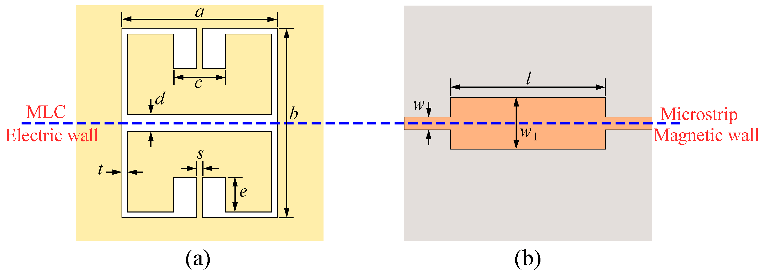
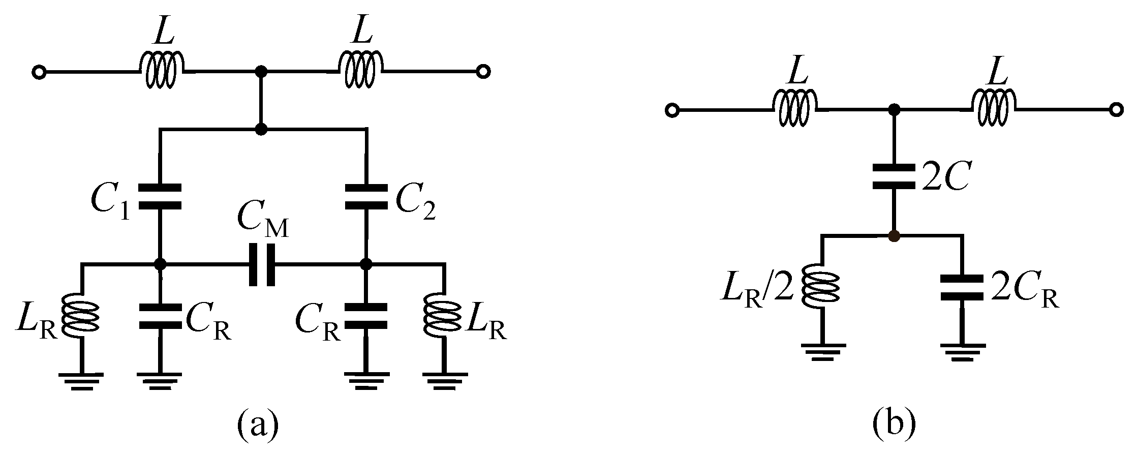
The proposed sensor is designed based on a microstrip transmission line loaded with a MLC resonator as shown in Figure 1. The electric wall of the MLC resonator is aligned with the magnetic wall (a plane, where the magnetic fields are distributed symmetrically on its two sides) of the microstrip transmission line. Such a structure is analyzed in detail in [46]. A general equivalent circuit model of the structure is presented in Figure 2a. In the circuit model, the and model the MLC resonator, where models the capacitive effect between each rectangular half of the resonator and the surrounding ground plane and is the inductance of the thin metallic traces connecting the rectangular halves to the ground plane. The is the mutual capacitance between the two halves of the MLC resonator. The L inductances model the equivalent inductance of the short microstrip line sections above the MLC resonator. Finally, and model the capacitive couplings between the microstrip transmission line and the two sides of the MLC resonator. When the microstrip transmission line is aligned with the resonator, as shown in Figure 1, the and capacitors will take the same value (). Therefore, there would be no voltage difference across the capacitor and the circuit takes the form shown in Figure 2b. In this condition, the transmission response () of the structure shows a single bandstop notch at defined as follows,
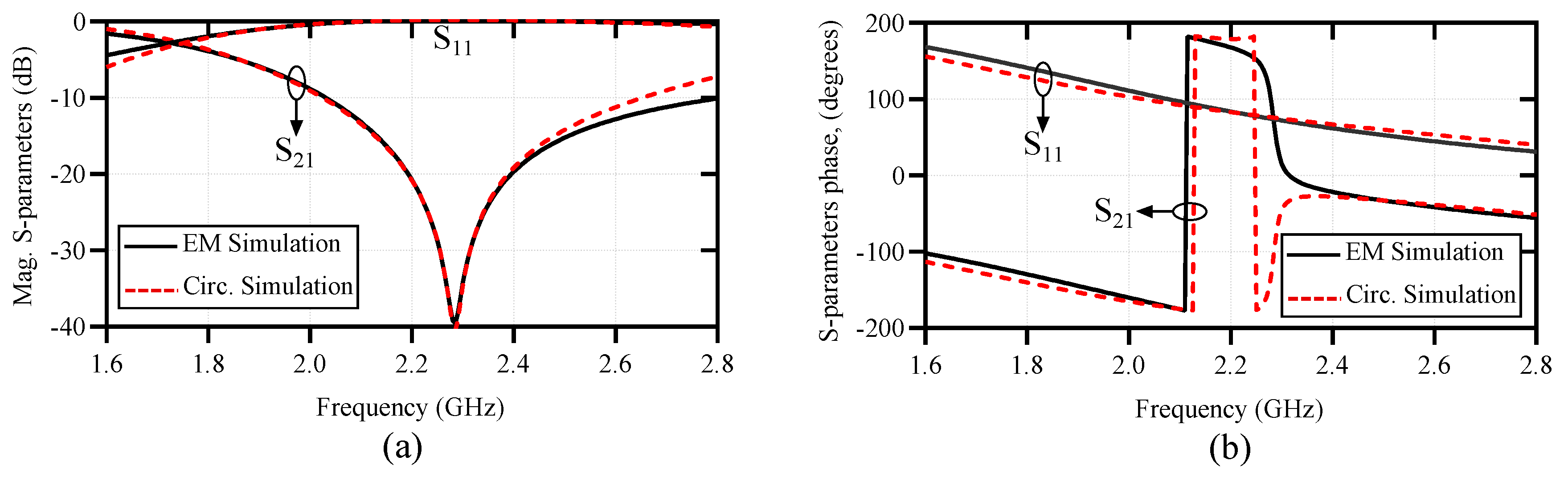
To validate the above analysis, a comparison between the equivalent circuit model and the full-wave electromagnetic (EM) simulation results of the structure in Figure 1 is presented in Figure 3. The geometrical dimensions of the structure are given in the caption of Figure 1, and the substrate used for the simulations is a mm thick Rogers RT6002 with and a loss tangent of . The agreement between the results in Figure 3 verifies the above analysis. The difference between the EM and circuit model results is mostly attributed to the mismatch between the short input sections and the wide microstrip line section above the resonator part. The circuit does not model the transition between the feeds and the wide microstrip line section. Now, if the symmetry is broken, a voltage difference will appear across the capacitor. As explained in [46], this excites the odd-mode resonance of the MLC causing a second bandstop notch in the transmission response of the structure. The symmetry might be broken in two ways: (i) by displacing the microstrip transmission line with respect to the electric wall of the MLC and (ii) by asymmetrically loading the halves of the MLC resonator with dielectric samples. By displacing the microstrip transmission line with respect to the MLC’s electric wall, the and capacitors take unequal values causing an asymmetry in the circuit. On the other hand, for asymmetrical dielectric loading on the two halves of the MLC, the two halves of the resonator show an unbalanced capacitive effect ( would be unequal for the two halves) causing asymmetry in the circuit.
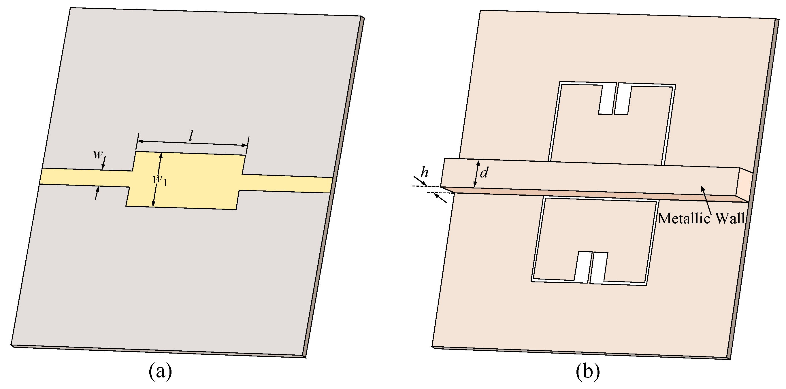
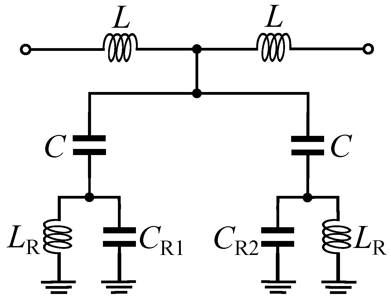
The basic operation principle of the differential sensor here is to introduce asymmetry by loading different dielectric materials into the two halves of the sensor. As explained above, this causes unbalanced values on the two sides of the resonator producing a second zero in the transmission response of the device. The relative permittivity of the sample under test can be obtained using the frequency difference between the two transmission zeros. However, the existence of capacitive coupling () degrades the sensitivity of the differential sensor [35,36,39]. In fact, by having a coupling between the two sensing elements (two halves of the resonator), any dielectric loading on one half of the sensor shifts both of the zero frequencies down. This reduces the frequency difference between them causing less sensitivity of the difference frequency with respect to the permittivity of the sample under test. To remove the capacitive coupling, a metallic wall is placed between the two halves of the MLC resonator as shown in Figure 4. In this configuration, is removed from the equivalent circuit model of the sensor and the circuit takes the form shown in Figure 5. The metallic wall must be high enough to prevent any electric field going from one side of the resonator to the other side. This height is optimized using simulations to completely decouple the two sides of the resonator. If there is any coupling between the two sides, by loading a dielectric slab on one side of the resonator frequency splitting happens, but the higher resonance frequency would also change instead of remaining constant. The d thickness should be larger than the skin depth at the operational frequency of the sensor. In reality, d is limited by fabrication, as it is challenging to fabricate a very thin wall. If the sensor is unloaded, then and the equivalent circuit model takes the form in Figure 2b. In this condition, there would be just one zero in the transmission response of the sensor. The frequency of this transmission zero is calculated as (1). Note that for the bare sensor in Figure 4, and are both larger than in the configuration of Figure 1. This is due to an additional capacitive effect between the metallic wall (that is attached to the ground plane) and the two rectangular patches of the MLC resonator. Now, if one of the sensing channels (resonator halves on the side of the metallic wall) is loaded with a test dielectric sample, then and two zeros appear in the transmission response of the sensor. The frequency of these transmission zeros are obtained as follows,
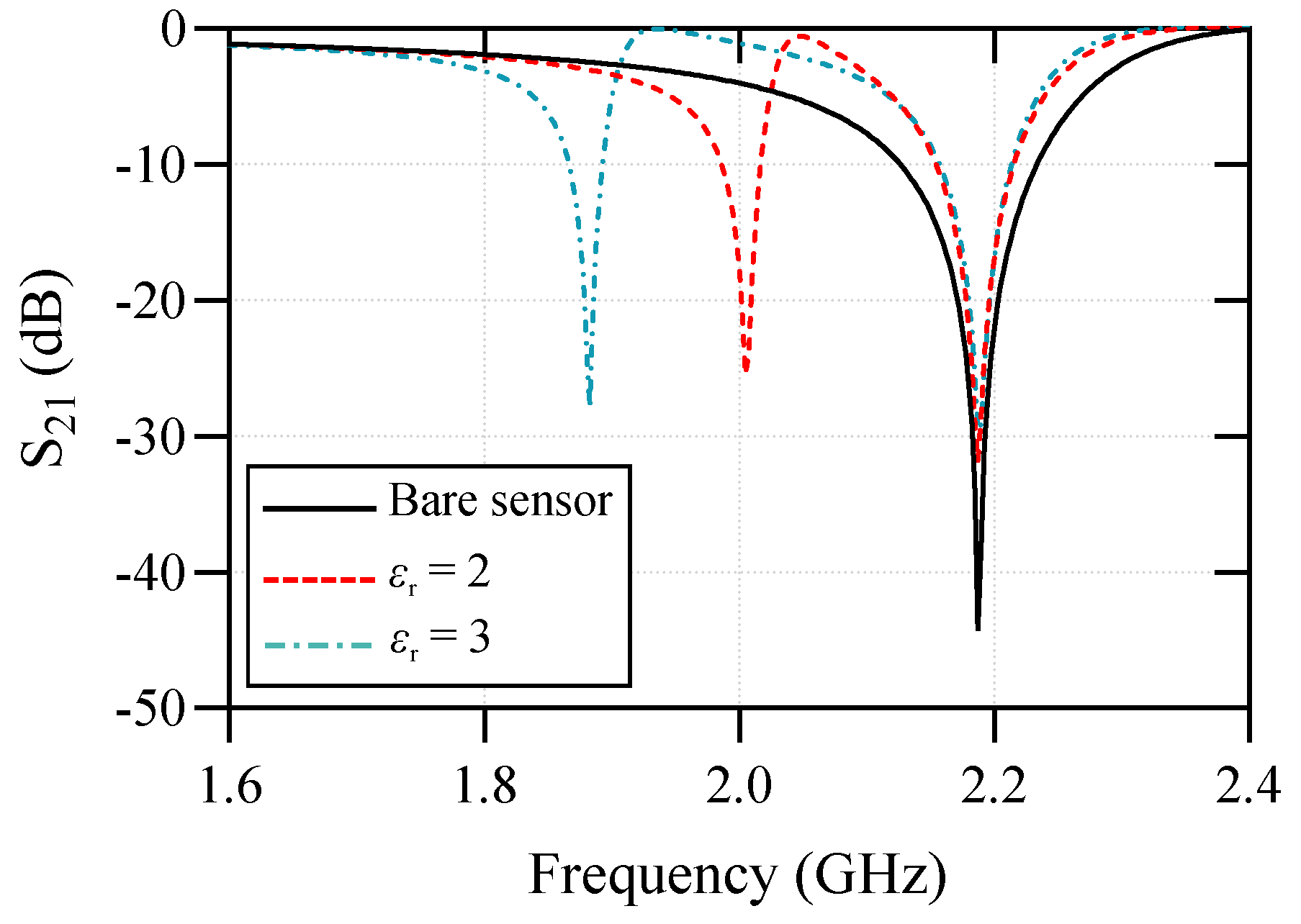
Here, the sensing variable is the frequency difference (), where one sensing channel is always unloaded and considered as a reference. This means is always constant, whereas is a function of the dielectric constant of the sample under test. A higher permittivity of the sample under test results in lower and higher . This is shown through the full-wave simulation results of the sensor, where the test channel is loaded with dielectric slabs of and in Figure 6. Here, by the relative permittivity or dielectric constant we mean the real part of the complex relative permittivity, and the focus of the presented work is permittivity measurement in low loss solid materials, where the imaginary part of the permittivity is much smaller than the real part.
3. Experimental Results
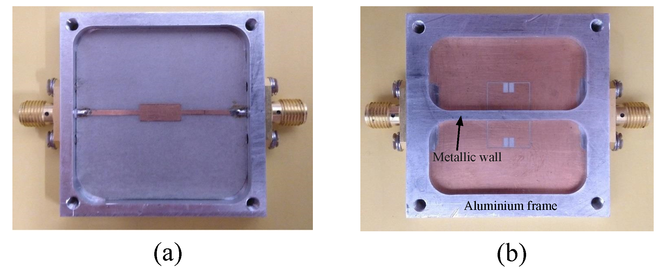
A prototype of the sensor is fabricated and tested for verifying the proposed differential frequency splitting sensing principle. The substrate used for fabrication is a mm thick Rogers RT6002 with a relative permittivity of and a loss tangent of . The front and back views of the fabricated sensor prototype are presented in Figure 7. An aluminum frame is designed and attached to the sensor keeping it from bending and potential damages during the measurements. The metallic wall separating the two sides of the sensor is machined out of the aluminum frame.
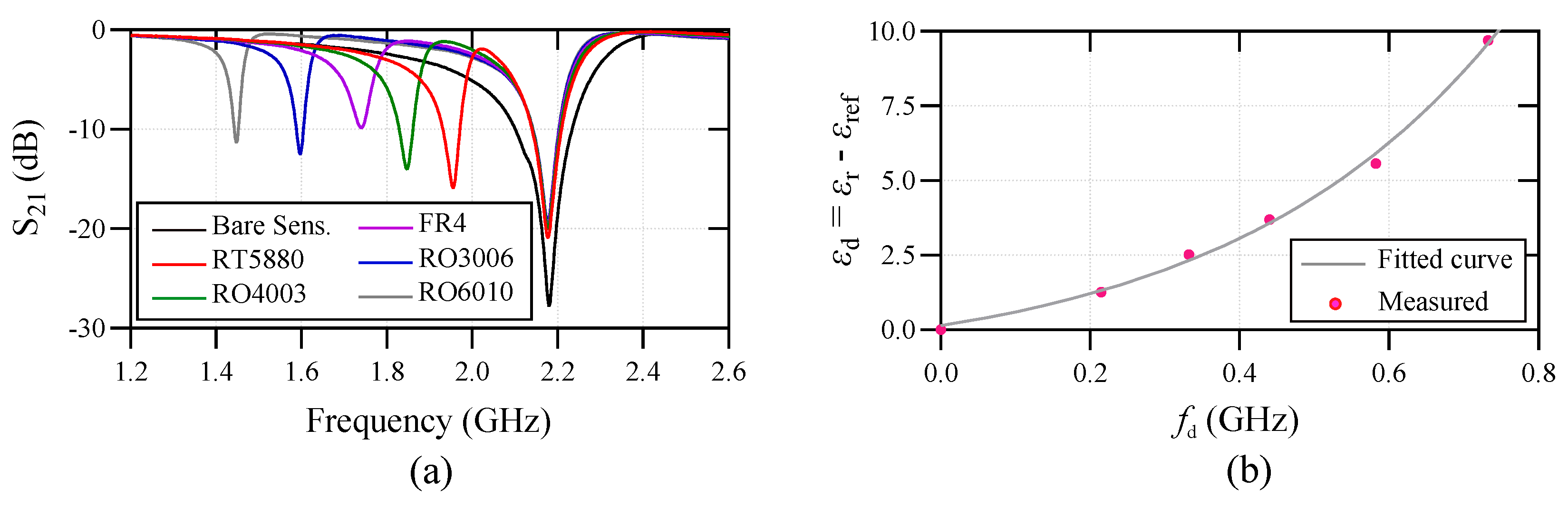
The sensor has been tested with five low loss dielectric slabs. The test dielectric slabs are mm thick Rogers RT5880 with and , mm thick Rogers RO4003 with and , mm thick FR4 with and , mm thick Rogers RO3006 with and , and mm thick Rogers RO6010 with and . The samples were cut in covering the whole sensing area. The dielectric samples were all thicker than mm to remove the cross-sensitivity with respect to the thickness. The dielectric samples should be large enough to cover the whole resonator area on each side. The samples are simply placed on the top of the resonator with no applied pressure for keeping the consistency during the measurements. The measured transmission coefficients of the sensor for these samples are plotted versus frequency in Figure 8a. In all measurements, the reference sensing channel is unloaded (reference is the bare side of the sensor). Based on Figure 8a, the higher resonance frequency, which is attributed to the reference channel, is always constant at GHz resembling the unloaded condition. Based on the measured results in Figure 8a, a mathematical sensing model is developed using the curve-fitting in MATLAB for determining the relative permittivity of the samples under test, using the difference between the resonance frequency of the reference sample and the sample under test. The obtained mathematical sensing model is as follows,
where, is the difference between the permittivity of the sample under test and the reference sample, and is the difference between the resonance frequencies of the test and reference sensing channels, where the reference channel is unloaded meaning . The relative permittivity of each test sample is then calculated using (4) and the results are tabulated in Table 1. As seen, the maximum permittivity measurement error using the designed sensor is less than , showing a high accuracy of the proposed sensor in determination of the relative permittivity of unknown dielectric samples. The actual values in Table 1 are taken from the commercial datasheets provided by Rogers Corporation [47].
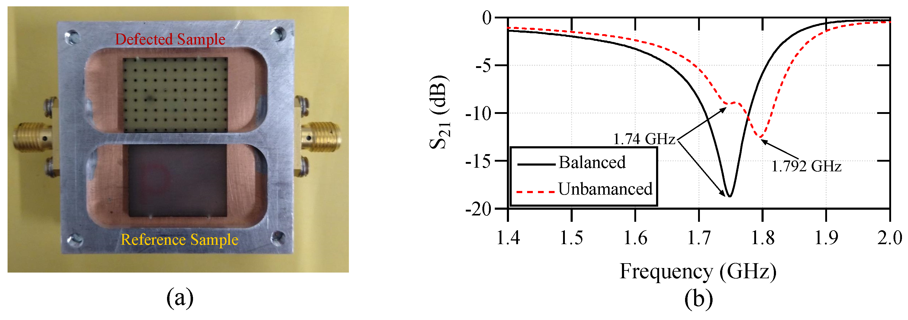
To investigate the functionality of the sensor as a comparator, it has been loaded with a perfect FR4 dielectric slab on the reference channel and a defected FR4 slab on the test sensing channel as shown in Figure 9a. The defects are implemented by laser milling of a hole array with each hole having a diameter of 1 mm and the center to center spacing of the adjacent holes is 2 mm. The measured transmission response of the sensor for this unbalanced loading is plotted in Figure 9b, where the transmission response for the balanced case (both channels loaded with perfect FR4 sample) is plotted as well. As seen in the plot, frequency splitting happens for the unbalanced loading, where the lower resonance frequency is exactly the same as the balanced case and the higher resonance frequency is happening at GHz. As the perfect and defected FR4 samples have relatively close permittivity values, the two resonances are close to each other forming weaker stopbands compared to the balanced case. Based on the sensing model in (4), the defects decrease the effective permittivity of the FR4 dielectric to .
Table 2 presents a comparison between the proposed differential sensor and the state-of-art frequency splitting sensors in the literature in terms of various performance metrics. In the table, presents the resonance frequency of the unloaded sensor. The average sensitivity () of each sensor is presented in the table. The average sensitivity is defined as
where n is the number of test samples (5 here), is the frequency splitting of the kth sample, and is the dielectric constant of the kth sample. As seen, the operation frequencies of the sensors in the literature are very different from each other. Therefore, for a fair comparison, the normalized sensitivity () is presented, where () is the average sensitivity normalized to for each sensor. Based on the table, the proposed sensor offers a very competitive performance compared to the rest of the designs in the literature. The designed sensor has the smallest size among the others offering more compatibility for integrated measurement systems. In addition, it shows a higher sensitivity with respect to the others except the sensor in [36]. Note that the sensing element in [36] is a cavity below the capacitive patch of the SIR, forming a parallel capacitance with the ground plane. This causes a higher fringing electric field for sensing. However, this sensor has a larger size with respect to the rest of the designs because of the ( is the guided wavelength at the resonance frequency of the bare sensor) spacing between the two sensing channels to avoid coupling between them.
4. Conclusions
A frequency splitting differential permittivity sensor is designed using a microstrip transmission line loaded with a magnetic-LC (MLC) resonator. A complementary structure of the resonator increases the fringing electric field, which results in a high sensitivity of the proposed sensor to the dielectric loadings. The two sensing channels of the sensor are decoupled using a metallic wall improving the differential sensing performance. The design concept has been verified by fabricating a sensor prototype and testing it with various dielectric test samples. A mathematical sensing model has been developed for measuring the relative permittivity of unknown samples based on the frequency splitting principle. The measurements and comparisons with the state-of-art sensors in the literature prove the high performance of the designed sensor in determining the relative permittivity of unknown solid dielectric materials.
Author Contributions
A.E. carried out the state-of-the-art research and wrote the paper. A.E. and G.B. carried out the experiments shown in the paper as well as the analysis of the data. J.S. contributed with his knowledge in the microwave circuits and proof read the manuscript. K.G. was director of the research. All authors have read and agreed to the published version of the manuscript.
Funding
There is no research funding for this article.
Acknowledgments
The authors would like to acknowledge David Welch of the RMIT University for his technical assistance in fabricating and assembling the sensor prototype.
Conflicts of Interest
The authors declare no conflict of interest.
References
- Horestani, A.K.; Shaterian, Z.; Naqui, J.; Martín, F.; Fumeaux, C. Reconfigurable and Tunable S-Shaped Split-Ring Resonators and Application in Band-Notched UWB Antennas. IEEE Trans. Antenn. Propag. 2016, 64, 3766–3776. [Google Scholar] [CrossRef]
- Ebrahimi, A.; Baum, T.; Ghorbani, K. Differential Bandpass Filters Based on Dumbbell-Shaped Defected Ground Resonators. IEEE Microw. Wirel. Compon. Lett. 2018, 28, 129–131. [Google Scholar] [CrossRef]
- Naqui, J.; Fernandez-Prieto, A.; Duran-Sindreu, M.; Mesa, F.; Martel, J.; Medina, F.; Martin, F. Common-mode suppression in microstrip differential lines by means of complementary split ring resonators: Theory and applications. IEEE Trans. Microw. Theory Tech. 2012, 60, 3023–3034. [Google Scholar] [CrossRef]
- Ebrahimi, A.; Baum, T.C.; Wang, K.; Scott, J.; Ghorbani, K. Differential Transmission Lines Loaded With Magnetic LC Resonators and Application in Common Mode Suppression. IEEE Trans. Circ. Syst. I Regular Pap. 2019, 66, 3811–3821. [Google Scholar] [CrossRef]
- Duran-Sindreu, M.; Velez, A.; Siso, G.; Velez, P.; Selga, J.; Bonache, J.; Martin, F. Recent advances in metamaterial transmission lines based on split rings. Proc. IEEE 2011, 99, 1701–1710. [Google Scholar] [CrossRef]
- Ebrahimi, A.; Withayachumnankul, W.; Al-Sarawi, S.F.; Abbott, D. Compact Second-Order Bandstop Filter Based on Dual-Mode Complementary Split-Ring Resonator. IEEE Microw. Wirel. Compon. Lett. 2016, 26, 571–573. [Google Scholar] [CrossRef]
- Abdolrazzaghi, M.; Daneshmand, M.; Iyer, A.K. Strongly Enhanced Sensitivity in Planar Microwave Sensors Based on Metamaterial Coupling. IEEE Trans. Microw. Theory Tech. 2018, 66, 1843–1855. [Google Scholar] [CrossRef] [Green Version]
- Cuenca, J.A.; Slocombe, D.R.; Porch, A. Temperature correction for cylindrical cavity perturbation measurements. IEEE Trans. Microw. Theory Tech. 2017, 65, 2153–2161. [Google Scholar] [CrossRef] [Green Version]
- Ansari, M.A.H.; Jha, A.K.; Akhtar, M.J. Design and Application of the CSRR-Based Planar Sensor for Noninvasive Measurement of Complex Permittivity. IEEE Sens. J. 2015, 15, 7181–7189. [Google Scholar] [CrossRef]
- Horestani, A.; Abbott, D.; Fumeaux, C. Rotation Sensor Based on Horn-Shaped Split Ring Resonator. IEEE Sens. J. 2013, 13, 3014–3015. [Google Scholar] [CrossRef]
- Ebrahimi, A.; Scott, J.; Ghorbani, K. Dual-Mode Resonator for Simultaneous Permittivity and Thickness Measurement of Dielectrics. IEEE Sens. J. 2019, 1, 185–192. [Google Scholar] [CrossRef]
- Withayachumnankul, W.; Jaruwongrungsee, K.; Fumeaux, C.; Abbott, D. Metamaterial-Inspired Multichannel Thin-Film Sensor. IEEE Sens. J. 2012, 12, 1455–1458. [Google Scholar] [CrossRef]
- Ebrahimi, A.; Withayachumnankul, W.; Al-Sarawi, S.F.; Abbott, D. Microwave microfluidic sensor for determination of glucose concentration in water. In Proceedings of the IEEE 15th Mediterranean Microwave Symposium (MMS), Lecce, Italy, 30 November–2 December 2015. [Google Scholar] [CrossRef]
- Shete, M.; Shaji, M.; Akhtar, M.J. Design of a Coplanar Sensor for RF Characterization of Thin Dielectric Samples. IEEE Sens. J. 2013, 13, 4706–4715. [Google Scholar] [CrossRef]
- Karimi, M.A.; Arsalan, M.; Shamim, A. Low Cost and Pipe Conformable Microwave-Based Water-Cut Sensor. IEEE Sens. J. 2016, 16, 7636–7645. [Google Scholar] [CrossRef]
- Ebrahimi, A.; Withayachumnankul, W.; Al-Sarawi, S.F.; Abbott, D. Microwave microfluidic sensor based on microstrip-line-coupled complementary resonator. In Proceedings of the IEEE 2nd Australian Microwave Symposium (AMS), Adelaide, Australia, 11–12 February 2016; pp. 21–22. [Google Scholar] [CrossRef]
- Herrojo, C.; Mata-Contreras, J.; Paredes, F.; Martín, F. Microwave Encoders for Chipless RFID and Angular Velocity Sensors Based on S-Shaped Split Ring Resonators. IEEE Sens. J. 2017, 17, 4805–4813. [Google Scholar] [CrossRef] [Green Version]
- Horestani, A.; Fumeaux, C.; Al-Sarawi, S.; Abbott, D. Displacement Sensor Based on Diamond-Shaped Tapered Split Ring Resonator. IEEE Sens. J. 2013, 13, 1153–1160. [Google Scholar] [CrossRef]
- Horestani, A.K.; Naqui, J.; Shaterian, Z.; Abbott, D.; Fumeaux, C.; Martín, F. Two-dimensional alignment and displacement sensor based on movable broadside-coupled split ring resonators. Sens. Actuators A Phys. 2014, 210, 18–24. [Google Scholar] [CrossRef] [Green Version]
- Clark, N.; Shaw, G.; Porch, A. Effect of surface stresses on microwave surface resistance and its impact for cavity perturbation measurements. IEEE Microw. Wirel. Compon. Lett. 2017, 27, 939–941. [Google Scholar] [CrossRef]
- Ebrahimi, A.; Withayachumnankul, W.; Al-Sarawi, S.F.; Abbott, D. Metamaterial-inspired rotation sensor with wide dynamic range. IEEE Sens. J. 2014, 14, 2609–2614. [Google Scholar] [CrossRef]
- Abdolrazzaghi, M.; Daneshmand, M. Dual Active Resonator for Dispersion Coefficient Measurement of Asphaltene Nano-Particles. IEEE Sens. J. 2017, 17, 7248–7256. [Google Scholar] [CrossRef]
- Ebrahimi, A.; Scott, J.; Ghorbani, K. Ultra-high sensitivity microwave sensor for microfluidic complex permittivity measurement. IEEE Trans. Microw. Theory Tech. 2019. accepted. [Google Scholar] [CrossRef]
- Su, W.; Cook, B.S.; Tentzeris, M.M. Additively Manufactured Microfluidics-Based Peel-and-Replace RF Sensors for Wearable Applications. IEEE Trans. Microw. Theory Tech. 2016, 64, 1928–1936. [Google Scholar] [CrossRef]
- Yi, X.; Wu, T.; Wang, Y.; Tentzeris, M.M. Sensitivity Modeling of an RFID-Based Strain-Sensing Antenna With Dielectric Constant Change. IEEE Sens. J. 2015, 15, 6147–6155. [Google Scholar] [CrossRef]
- Naqui, J.; Durán-Sindreu, M.; Martín, F. Alignment and position sensors based on split ring resonators. Sensors 2012, 12, 11790–11797. [Google Scholar] [CrossRef] [Green Version]
- Naqui, J.; Duránn-Sindreu, M.; Martín, F. Novel Sensors Based on the Symmetry Properties of Split Ring Resonators (SRRs). Sensors 2011, 11, 7545–7553. [Google Scholar] [CrossRef] [Green Version]
- Zarifi, M.H.; Sohrabi, A.; Shaibani, P.M.; Daneshmand, M.; Thundat, T. Detection of Volatile Organic Compounds Using Microwave Sensors. IEEE Sens. J. 2015, 15, 248–254. [Google Scholar] [CrossRef]
- Zarifi, M.H.; Daneshmand, M. Monitoring Solid Particle Deposition in Lossy Medium Using Planar Resonator Sensor. IEEE Sens. J. 2017, 17, 7981–7989. [Google Scholar] [CrossRef]
- Hamzah, H.; Lees, J.; Porch, A. Split ring resonator with optimised sensitivity for microfluidic sensing. Sens. Actuators A Phys. 2018, 276, 1–10. [Google Scholar] [CrossRef]
- Ebrahimi, A.; Scott, J.; Ghorbani, K. Microwave reflective biosensor for glucose level detection in aqueous solutions. Sens. Actuators A Phys. 2019, 111662. [Google Scholar] [CrossRef]
- Velez, P.; Grenier, K.; Mata-Contreras, J.; Dubuc, D.; Martín, F. Highly-sensitive microwave sensors based on open complementary split ring resonators (OCSRRs) for dielectric characterization and solute concentration measurement in liquids. IEEE Access 2018, 6, 48324–48338. [Google Scholar] [CrossRef]
- Vélez, P.; Muñoz-Enano, J.; Gil, M.; Mata-Contreras, J.; Martín, F. Differential Microfluidic Sensors Based on Dumbbell-Shaped Defect Ground Structures in Microstrip Technology: Analysis, Optimization, and Applications. Sensors 2019, 19, 3189. [Google Scholar] [CrossRef] [PubMed] [Green Version]
- Vélez, P.; Muñoz-Enano, J.; Grenier, K.; Mata-Contreras, J.; Dubuc, D.; Martín, F. Split Ring Resonator-Based Microwave Fluidic Sensors for Electrolyte Concentration Measurements. IEEE Sens. J. 2018, 19, 2562–2569. [Google Scholar] [CrossRef]
- Ebrahimi, A.; Scott, J.; Ghorbani, K. Differential Sensors Using Microstrip Lines Loaded With Two Split-Ring Resonators. IEEE Sens. J. 2018, 18, 5786–5793. [Google Scholar] [CrossRef]
- Naqui, J.; Damm, C.; Wiens, A.; Jakoby, R.; Su, L.; Mata-Contreras, J.; Martín, F. Transmission lines loaded with pairs of stepped impedance resonators: modeling and application to differential permittivity measurements. IEEE Trans. Microw. Theory Tech. 2016, 64, 3864–3877. [Google Scholar] [CrossRef] [Green Version]
- Su, L.; Mata-Contreras, J.; Vélez, P.; Martín, F. Configurations of splitter/combiner microstrip sections loaded with stepped impedance resonators (SIRs) for sensing applications. Sensors 2016, 16, 2195. [Google Scholar] [CrossRef] [Green Version]
- Su, L.; Mata-Contreras, J.; Vélez, P.; Martín, F. Splitter/combiner microstrip sections loaded with pairs of complementary split ring resonators (CSRRs): Modeling and optimization for differential sensing applications. IEEE Trans. Microw. Theory Tech. 2016, 64, 4362–4370. [Google Scholar] [CrossRef]
- Ebrahimi, A.; Scott, J.; Ghorbani, K. Transmission Lines Terminated With LC Resonators for Differential Permittivity Sensing. IEEE Microw. Wirel. Compon. Lett. 2018, 28, 1149–1151. [Google Scholar] [CrossRef]
- Ebrahimi, A.; Ahmed, A.; Mapleback, B.; Scott, J.; Ghorbani, K. Microstrip Lines Loaded with Bandstop Resonators for High Resolution Permittivity Sensing. In Proceedings of the Asia-Pacific Microwave Conference (APMC), Kyoto, Japan, 6–9 November 2018; pp. 926–928. [Google Scholar] [CrossRef]
- Abduljabar, A.A.; Hamzah, H.; Porch, A. Double Microstrip Microfluidic Sensor for Temperature Correction of Liquid Characterization. IEEE Microw. Wirel. Compon. Lett. 2018, 28, 735–737. [Google Scholar] [CrossRef]
- Vélez, P.; Muñoz-Enano, J.; Martín, F. Differential Sensing Based on Quasi-Microstrip Mode to Slot-Mode Conversion. IEEE Microw. Wireless Compon. Lett. 2019, 29, 690–692. [Google Scholar] [CrossRef]
- Muñoz-Enano, J.; Vélez, P.; Gil, M.; Martín, F. An Analytical Method to Implement High Sensitivity Transmission Line Differential Sensors for Dielectric Constant Measurements. IEEE Sens. J. 2019. [Google Scholar] [CrossRef]
- Gil, M.; Vélez, P.; Aznar-Ballesta, F.; Muñoz-Enano, J.; Martín, F. Differential Sensor based on Electro-Inductive Wave (EIW) Transmission Lines for Dielectric Constant Measurements and Defect Detection. IEEE Trans. Anten. Propag. 2019. [Google Scholar] [CrossRef]
- Ebrahimi, A.; Withayachumnankul, W.; Al-Sarawi, S.; Abbott, D. High-Sensitivity Metamaterial-Inspired Sensor for Microfluidic Dielectric Characterization. IEEE Sens. J. 2014, 14, 1345–1351. [Google Scholar] [CrossRef] [Green Version]
- Ebrahimi, A.; Withayachumnankul, W.; Al-Sarawi, S.F.; Abbott, D. Dual-mode behavior of the complementary electric-LC resonators loaded on transmission line: Analysis and applications. J. Appl. Phys. 2014, 116, 083705. [Google Scholar] [CrossRef] [Green Version]
- Rogers Corporation. Available online: https://www.rogerscorp.com/ (accessed on 14 February 2020).
- Vélez, P.; Su, L.; Grenier, K.; Mata-Contreras, J.; Dubuc, D.; Martín, F. Microwave Microfluidic Sensor Based on a Microstrip Splitter/Combiner Configuration and Split Ring Resonators (SRRs) for Dielectric Characterization of Liquids. IEEE Sens. J. 2017, 17, 6589–6598. [Google Scholar] [CrossRef] [Green Version]
Figure 1.
Layout of a microstrip transmission line loaded with a magnetic-LC resonator. (a) Bottom view and (b) top view. The microstrip metallization is shown in orange, the ground plane metallization in yellow, and the dielectric substrate is shown with gray color. The geommetrical dimensions are mm, mm, , mm, mm, mm, mm, and mm.

Figure 2.
Equivalent circuit model of a microstrip line loaded with a MLC resonator. (a) General circuit model of the structure. (b) The circuit model, when the MLC electric wall is aligned with the magnetic wall of the microstrip transmission line.
Figure 2.
Equivalent circuit model of a microstrip line loaded with a MLC resonator. (a) General circuit model of the structure. (b) The circuit model, when the MLC electric wall is aligned with the magnetic wall of the microstrip transmission line.

Figure 3.
Comparison between the full-wave electromagnetic and the circuit model simulation results of a microstrip line loaded with MLC resonator, when the electric wall of the resonator is aligned with the magnetic wall of the microstrip transmission line. (a) Amplitude response and (b) phase response. The extracted lumped element values are nH, pF, pF, and nH.

Figure 4.
The designed differential sensor using a metallic wall separating the two halves of a MLC resonator. (a) Front view of the sensor. (b) Back view of the sensor. All the dimensions are the same as Figure 1 except mm and mm here. In addition, mm and mm.
Figure 4.
The designed differential sensor using a metallic wall separating the two halves of a MLC resonator. (a) Front view of the sensor. (b) Back view of the sensor. All the dimensions are the same as Figure 1 except mm and mm here. In addition, mm and mm.

Figure 5.
Equivalent circuit model of the sensor in Figure 4.
Figure 5.
Equivalent circuit model of the sensor in Figure 4.

Figure 6.
Simulated for the bare sensor and when one of the sensing elements is loaded with a test sample of and .
Figure 6.
Simulated for the bare sensor and when one of the sensing elements is loaded with a test sample of and .

Figure 7.
The fabricated sensor prototype (a) front view and (b) back view.

Figure 8.
(a) The measured transmission responses of the sensor for various test dielectric samples. (b) The measured and curve fitted frequency splitting for various dielectric samples.
Figure 8.
(a) The measured transmission responses of the sensor for various test dielectric samples. (b) The measured and curve fitted frequency splitting for various dielectric samples.

Figure 9.
(a) The sensor setup as a comparator using a perfect and a defected FR4 dielectric slabs. (b) The measured responses of the sensor with balanced and unbalanced loadings of FR4 samples.
Figure 9.
(a) The sensor setup as a comparator using a perfect and a defected FR4 dielectric slabs. (b) The measured responses of the sensor with balanced and unbalanced loadings of FR4 samples.


Table 1.
Comparison between the measured permittivities of the samples under test and using (4) and the actual values taken from the commercial datasheets.
Table 1.
Comparison between the measured permittivities of the samples under test and using (4) and the actual values taken from the commercial datasheets.
| Sample | Meas. (GHz) | Calc. | Meas. | Actual | Error (%) |
|---|---|---|---|---|---|
| RT5880 | |||||
| RO4350 | 3 | ||||
| FR4 | |||||
| RO3006 | |||||
| RO6010 |
Table 2.
Comparison between the performance of the designed frequency splitting sensor and the state-of-art ones.
© 2020 by the authors. Licensee MDPI, Basel, Switzerland. This article is an open access article distributed under the terms and conditions of the Creative Commons Attribution (CC BY) license (http://creativecommons.org/licenses/by/4.0/).
Share and Cite
MDPI and ACS Style
Ebrahimi, A.; Beziuk, G.; Scott, J.; Ghorbani, K. Microwave Differential Frequency Splitting Sensor Using Magnetic-LC Resonators. Sensors 2020, 20, 1066. https://doi.org/10.3390/s20041066
AMA Style
Ebrahimi A, Beziuk G, Scott J, Ghorbani K. Microwave Differential Frequency Splitting Sensor Using Magnetic-LC Resonators. Sensors. 2020; 20(4):1066. https://doi.org/10.3390/s20041066
Chicago/Turabian StyleEbrahimi, Amir, Grzegorz Beziuk, James Scott, and Kamran Ghorbani. 2020. "Microwave Differential Frequency Splitting Sensor Using Magnetic-LC Resonators" Sensors 20, no. 4: 1066. https://doi.org/10.3390/s20041066
Note that from the first issue of 2016, this journal uses article numbers instead of page numbers. See further details here.