Metal–Organic Framework Thin Films: Fabrication, Modification, and Patterning

School of Chemical, Biological and Environmental Engineering, Oregon State University, Corvallis 97330, OR, USA
*
Author to whom correspondence should be addressed.
Processes 2020, 8(3), 377; https://doi.org/10.3390/pr8030377
Submission received: 10 February 2020
/
Revised: 17 March 2020
/
Accepted: 19 March 2020
/
Published: 24 March 2020
(This article belongs to the Special Issue Materials Processing for Production of Nanostructured Thin Films)
Abstract
:Metal–organic frameworks (MOFs) have been of great interest for their outstanding properties, such as large surface area, low density, tunable pore size and functionality, excellent structural flexibility, and good chemical stability. A significant advancement in the preparation of MOF thin films according to the needs of a variety of applications has been achieved in the past decades. Yet there is still high demand in advancing the understanding of the processes to realize more scalable, controllable, and greener synthesis. This review provides a summary of the current progress on the manufacturing of MOF thin films, including the various thin-film deposition processes, the approaches to modify the MOF structure and pore functionality, and the means to prepare patterned MOF thin films. The suitability of different synthesis techniques under various processing environments is analyzed. Finally, we discuss opportunities for future development in the manufacturing of MOF thin films.
1. Introduction
Metal–organic frameworks (MOFs) are a class of inorganic–organic hybrid crystalline microporous materials consisting of a highly ordered array of metal cations connected by multidentate organic linkers. The regular and extended network built by metal ions (or clusters) and organic linkers often forms a repeating cage-like structure, which grants MOFs an extensive internal surface area. In contrast to other porous materials, MOFs also possess designable structures that can be engineered with tailored pores for selective adsorption of specific gases [1]. Moreover, MOFs show outstanding features as in structural flexibility, thermal and chemical stability, etc., which grant MOFs great potential in numerous applications, such as gas storage and separation [2,3,4,5], liquid purification [6,7,8,9], catalysis [10,11,12,13], gas/chemical sensing [14,15,16,17,18], and energy production [19,20,21,22]. Other than direct applications, MOFs have also been used as precursors/templates for the production of inorganic functional materials with unique designability [23]. According to the needs in various applications, thousands of MOFs have been synthesized by now since being reported in the 1990s [1,24,25,26]. Nowadays, MOFs are available in various structures, such as nanocrystals (NCs) [27], nanospheres [28], nanosheets [29], needles [30], hierarchical monoliths [31], thin films (TFs) [32], membranes [33], and glasses [34,35,36]. Among these structures, MOF-TFs are drawing increasing attention due to their tremendous potential in the development of nanotechnology-enabling applications, such as optics [37], photonics [38], electronics [39], catalytic coatings [40], sensing [41,42,43,44], solar cell [45], battery [46], and supercapacitor [44]. One thing to notice is that MOF-TFs cannot be differentiated from MOF membranes by their chemical composition or by their selection of substrates. Concerning the definition of a membrane [47], which should be a medium that allows transfer to occur under a certain driving force, a TF [48] does not have such a restriction. The main difference between TFs and membranes lies in their functions, although there is reporting of freestanding MOF-TFs that can function as a membrane due to its porosity [49].
A significant amount of research is devoted to the fabrication, characterization, and application of MOF-TFs. MOF-TFs deposited on substrates of various functions enable different applications. For example, those on quartz crystal microbalance (QCM) substrates allow for the study of adsorption within MOF layers [50,51,52], those on gold substrates realize surface plasmon resonance (SPR) spectroscopy [53], and those on conducting electrodes open up a way for electrical and electrochemical applications [54,55]. The selection of substrate is crucial in the fabrication of MOF-TFs, especially in the deposition process based on hydro/solvothermal mother solution synthesis that requires good heterogeneous nucleation and growth of MOFs. To date, the fabrication of MOF-TFs has been realized on various substrates, such as nonplanar substrates [56], planar substrates [57], flexible substrates [42,58], and substrates terminated with different functional groups on the surface [59,60]. In spite of these extensive studies, engineering MOF-TFs with a controllable thickness and structure and precise chemical composition has always been a challenge. Commercialization involving scale-up production with an effective cost is an additional challenge [61]. As a result, investigation regarding novel synthesis approaches for the manufacturing of MOF-TFs continues.
Since there are many excellent reviews [33,62,63,64,65,66] focusing on the fabrication of MOF membranes, including the concept of mixed matrix membranes [67,68], this review covers current progress on the manufacturing of MOF-TFs. It summarizes and analyzes various fabrication processes for MOF-TFs, approaches for the modification of architectures and pore functionality in MOF-TFs, means for the preparation of patterned MOF-TFs, and application of different synthesis strategies under various processing environments. This review aims to advance the understanding of the processing of MOF-TFs to realize a more controllable, scalable, and eco-friendly synthesis. Concerning these objectives, some prospects on future opportunities for the development of the manufacturing of MOF-TFs are discussed at the end.
2. General Fabrication Techniques for MOF-TFs
Several excellent reviews focusing on MOFs, including MOF-TFs, have been published [37,69,70,71,72,73,74,75,76,77]. These papers review existing and potential applications, as well as the synthesis methods of MOF-TFs. However, regarding the fabrication techniques, these reviews focus on more commonly used approaches, such as hydro/solvothermal synthesis, the stepwise layer-by-layer (LBL) deposition method, and the electrochemical method. Considering the extensive discussion about the diverse synthesis of MOFs in other structures, such as nanoparticles (NPs) [78], composite structures [79], and membranes [33], here we focus on the fabrication of MOF-TFs, giving a comprehensive review on various synthesis strategies that are reported for MOF-TFs (including patterns) and offering a direction for future development for the green fabrication of MOF-TFs.
Classification of Fabrication Techniques
The classification of fabrication techniques in this review is according to the phase of the precursors in the synthesis reaction, such as liquid, solid, vapor, and gel. In the section of general fabrication techniques for MOF-TFs, we will focus the discussion on the processes using two precursors, one of which is the metal precursor and the other the organic precursor. The studies that require more than one metal or organic species will be discussed in the section of modification of MOF-TFs, with an emphasis on the manufacturing of TF structure/composition with modified functionality.
The discussion on general fabrication techniques will be grouped into three sections, including liquid–liquid synthesis methods, liquid–solid synthesis methods, and all other types of synthesis methods (i.e., solid–solid synthesis methods, vapor–solid synthesis methods, vapor–gel synthesis methods, and the post-assembly method).
3. General Liquid–Liquid Synthesis
Most syntheses of MOF-TFs are carried out via liquid-phase reaction, where both the metal and the organic precursors are dissolved in a solvent before the reaction. Typically, the dissolved precursors are either well mixed to prepare a solution mixture as the mother solution before the addition of substrates (such as in a direct solvothermal synthesis) or used separately in contact with the substrates in a sequential manner (such as in a stepwise LBL deposition). The high concentration of ionized reactants (i.e., the metal cations and the deprotonated organic linkers) in the solution leads typically to a homogeneous reaction in the solvent phase and simultaneously a heterogeneous reaction at the substrate surface [80]. There is competition between these two reactions, where the homogeneous reaction results in the formation of MOF crystals in the solvent while the heterogeneous reaction brings about the formation of MOF-TFs on the substrate surface. Therefore, promoting the heterogeneous reaction and suppressing the homogeneous reaction is a promising solution to realize the green and economical synthesis of high-quality MOF-TFs with good uniformity and continuity.
3.1. Direct Synthesis
Although numerous fabrication techniques have been developed for MOF-TFs, a one-pot hydro/solvothermal batch synthesis strategy is still the primary way and serves as the foundation for the development of many other synthesis strategies. Hydrothermal synthesis refers to those that happen in an aqueous solution above the boiling point of water while solvothermal synthesis is in a non-aqueous solution at relatively high temperatures [81]. Both types of synthesis often proceed in a sealed reactor, such as an autoclave, and a pressure vessel. In a typical hydro/solvothermal synthesis, the substrate is placed in a mixture of precursor solutions for MOFs and is subjected to a reaction at a high temperature. This one-pot hydro/solvothermal synthesis strategy for MOF-TFs can be categorized into two subcategories, i.e., the direct growth on unmodified substrates, and the secondary growth that involves the preparation of functional substrate surfaces. The main issues in the direct synthesis are the lack of control in preparing a homogeneous TF and possible substrate corrosion.
Based on the concept of direct synthesis, Cui et al. [82] realized the fabrication of MOF-TFs on rough surfaces via an in situ hydrothermal synthesis strategy. Stainless steel wires were used as the substrates, which were etched by hydrofluoric acid before the reaction since a rough surface can improve the retention of particles and thereby promotes the heterogeneous nucleation and growth of MOFs. After 8 h of reaction at 120 °C, complete coverage of HKUST-1 (Cu3(BTC)2(H2O)3, where BTC = 1,3,5-benzenetricarboxylate; also known as MOF-199) TF with a thickness of about 40 µm was obtained on an etched SSW (Figure 1A). The resulting HKUST-1-coated SSWs were tested for solid-phase microextraction for volatile and harmful benzene homologues, acquiring a low limit of detection that was 8.3–23.3 ng/L. Later, Sheberla et al. [83] reported the fabrication of MOF-TFs on smooth surfaces via an in situ solvothermal synthesis strategy. Ni3(HITP)2 MOF-TFs, where HITP = 2,3,6,7,10,11-hexaiminotriphenylene, were fabricated directly on quartz substrates under the reaction conditions in this study and a microporous structure and ultrahigh electrical conductivity was obtained that was of interest in electronic devices. The conductivity of the resulting Ni3(HITP)2 MOF-TFs reached 40 S/cm, which stood for the best records for MOFs and coordination polymers at the time. Campbell et al. [84] achieved continuous and dense Mg-MOF-74 (Mg2DOBDC, where DOBDC = 2,5-dihydroxyterephthalate) TFs directly on porous alumina (Al2O3) substrates via an in situ solvothermal synthesis strategy (Figure 1B). In this report, the process was optimized by tuning the reaction conditions (i.e., reaction time, the dose of precursors, and the composition of solvents) that could influence the TF formation process and resulting thickness and morphology. A proper solvent composition of N,N-dimethylformamide (DMF):water:ethanol was reported, 16:2:2, in order to obtain well-intergrown Mg-MOF-74 TFs. In this study, it was noticed that, by fixing all the other reaction parameters, the film thickness increased from 1.6 to 1.8 μm when increasing the reaction time from 2.5 to 6 h. The results corresponded to a decreased growth rate that was from 10.67 to 5.00 nm/minute when increasing the reaction time, which implies a common disadvantage for solvothermal synthesis. Many types of MOF-TFs, such as MOF-5 (Zn4O(BDC)3, where BDC = 1,4-benzodicarboxylate; as known as IRMOF-1) [85], PCN-221 (Zr8(μ4-O)6(OH)8(TCPP)3, where TCPP = tetrakis(4-carboxylatephenyl)porphyrin), PCN-222 (Zr6(μ3-OH)8(OH)8(TCPP)2), and PCN-223 (Zr6(μ3-O)4(μ3-OH)4(TCPP)3) [86], can be achieved via direct synthesis.
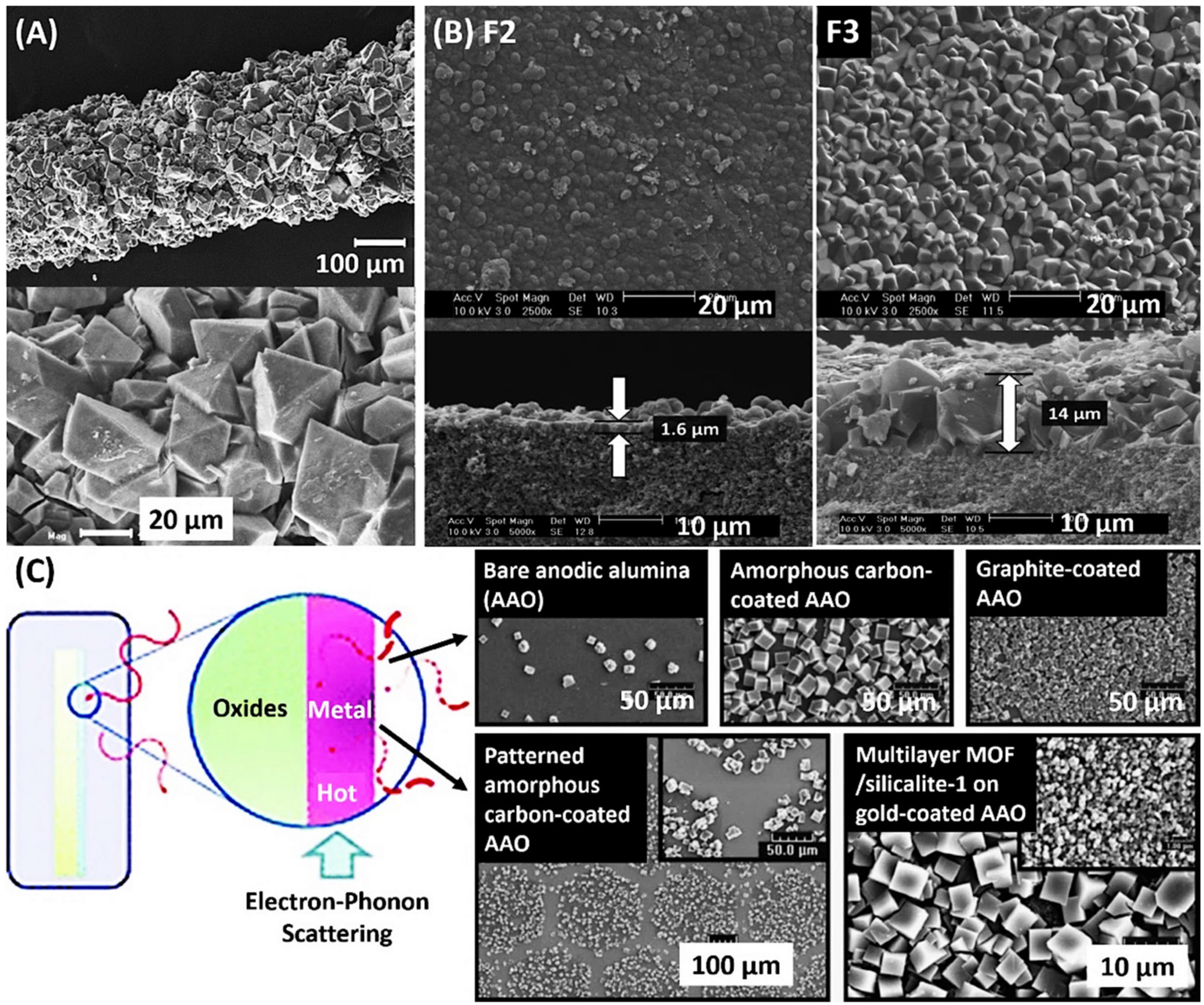
Different from the traditional direct synthesis based on the one-pot hydro/solvothermal synthesis, microwave irradiation was introduced into the reaction scheme by expediting the reaction of MOF-TFs because crystal growth is generally faster under microwave irradiation. With this consideration, Yoo and Jeong [56] reported a rapid synthesis of MOF-5 TFs on various surfaces that was finished in 5–30 s under microwave irradiation with a power of 500 W (Figure 1C). Uncoated, amorphous carbon-coated, graphite-coated, and gold-coated Al2O3 supports were investigated as substrates. The results illustrated an advantage of substrate surface modification in the fabrication of MOF-TFs (including patterns) that we will discuss in the secondary growth section. Furthermore, Bux et al. [87] reported that the microwave-assisted fabrication of MOF-TFs does not necessarily require a chemically modified substrate surface, nor an atomically smooth surface with electrostatic compatibility. In this study, dense and continuous ZIF-8 (Zn(2-mIm)2, where 2-mIm = 2-methylimidazole) TFs were acquired directly on porous titanium oxide substrates via a microwave-assisted solvothermal synthesis after 4 h of reaction at 100 °C. This type of synthesis strategy has also succeeded in the fabrication of other types of MOF-TFs on various substrates [88], demonstrating a great potential of microwave irradiation in the development of rapid synthesis strategies.
3.2. Secondary Growth
Although traditional hydro/solvothermal synthesis in the fabrication of MOF-TFs has been successful, it is still challenging to fabricate continuous MOF-TFs on unmodified substrates because the heterogeneous nucleation of MOF crystals on substrate surfaces is commonly inefficient [89]. Moreover, it is difficult for MOF crystals that have formed in solution to adhere to substrate surfaces due to the lack of binding sites. One of the main strategies to improve the heterogeneous nucleation and growth of MOF-TFs is through substrate surface modification [90]. This type of synthesis strategy is classified as secondary growth, which commonly involves the functionalization of the substrate by adding a functional layer on the surface before the synthesis. Other than traditional one-pot hydro/solvothermal synthesis, the secondary growth is often conducted with other synthesis strategies to achieve controllable formation of MOF-TFs [91].
Under the concept of secondary growth, functional group-terminated surfaces have been widely studied to improve the heterogeneous nucleation of MOF-TFs [92], as they can help to anchor the metal/metal-oxo nodes and/or organic linkers on substrate surfaces. Many kinds of functional layers are used for substrate surface modification, which can be grouped into two categories, including the organic functional layers, such as self-assembled monolayers (SAMs) and polymers, and the inorganic-involving functional layers, such as MOF NCs and metal oxide NPs.
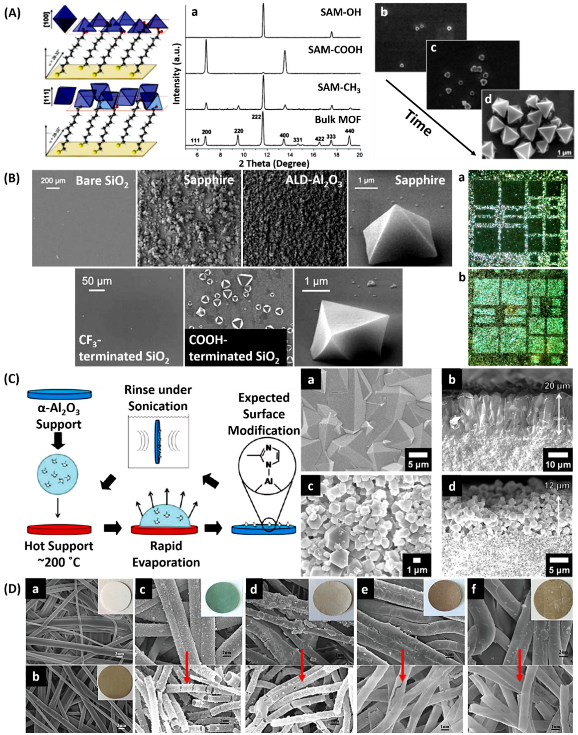
SAMs are a class of organic functional layers used extensively in the fabrication of MOF-TFs. Commonly, SAMs consist of organothiol-based chains prepared on solid surfaces [93] to coordinate with MOF precursors. By changing the type of functional group on organothiol-based chains or the density, the growth orientation of MOF-TFs can be systematically controlled [94], contributing to the fabrication of highly oriented MOF-TFs. Hermes et al. [59] achieved the patterning of MOF-5 TFs based on patterned COOH-/CF3-terminated SAMs prepared by microcontact printing (μCP) on gold surfaces. In this study, a mixture of Zn(NO3)2 and terephthalic acid was prepared in pure dimethylformamide at 75 °C as the mother solution for MOF-5. After mixing for 72 h, the solution was heated to 105 °C and rapidly cooled down to 25 °C to allow the crystallization of MOF-5. A clear supersaturated reaction mixture was obtained by filtration. Then, the μCP-patterned SAMs of 16-mercaptohexadecanoic acid (MHDA) and 1H,1H,2H,2H-perfluorododecane thiol (PFDT) on Au(111) were immersed in the reaction mixture, resulting in the selective deposition of MOF-5 on patterned areas. Biemmi et al. [94] reported a study on the influence of the type of SAMs on the orientation of the resulting MOF-TFs (Figure 2A). Based on the different coordination of –OH and –COOH groups, the resulting HKUST-1 TFs showed preferred [111] and [100] growth directions on the gold surfaces, respectively. A controlled orientation is beneficial in MOFs because it influences the pore system in MOF-TFs, which could open the way for more advanced applications based on improved adsorption [94]. Liu et al. [95] discovered that even by the same functional group-terminated SAMs, the orientation of the resulting HKUST-1 TFs could be different by varying the density of the functional groups. Zacher et al. [96] achieved highly oriented HKUST-1 TFs on bare Al2O3 surfaces and SAMs prepared on silicon dioxide (SiO2) surfaces (Figure 2B). In the study, it was observed that there was no crystal nucleation on the bare SiO2 surface based on oxidized Si wafer while densely packed polycrystalline agglomerated HKUST-1 microcrystals formed on sapphire (Al2O3) and atomic layer deposition (ALD)-Al2O3 surfaces. It was stated that because of electrostatic effct the nucleation of HKUST-1 preferred the basic surface of Al2O3 rather than the acidic surface of SiO2. Therefore, the alkaline environment in the reaction system would be another key aspect to consider during experiment design depending on the type of MOFs. Other than MOF-5 and HKUST-1 TFs, different kinds of MOF-TFs are achieved by similar methods, such as Fe-MIL-88B-NH2 (Fe3O(BDC-NH2)3Cl, where BDC-NH2 = 2-amino-1,4-benzenedicarboxylate) and its isomer Fe-MIL-101-NH2 [60], and CAU-1 (Al4(OH)2(OCH3)4(BDC-NH2)3) [97].
Similar to SAM-assisted synthesis, there is one type of surface modification based on the organic linkers of the desired MOF. McCarthy et al. [98] demonstrated the effectiveness of functionalizing α-Al2O3 substrates with organic compounds, which was benzimidazole (bIm) for ZIF-7 and 2-mIm for ZIF-8, via a rapid evaporation process (Figure 2C). This simple surface modification procedure provided strong covalent bonds between the α-Al2O3 substrates and the imidazolate linkers, which is effective in promoting the heterogeneous nucleation and growth of MOF-TFs. Take the synthesis of well-intergrown ZIF-8 in this study, for example. For substrate preparation, polished α-Al2O3 substrates were dried in a convection oven at 200 °C for 2 h. Then, 0.5–1 mL if methanolic solution of 2-mIm was dropped on a 2.2-cm2 substrate. After it was dried, the substrate was removed from the oven and sonicated in methanol for about 30 s. A thoroughly-modified substrate was prepared by repeating this process about six times. The formation of ZIF-8 films on the modified substrate was finished via traditional solvothermal treatment in the ZIF-8 mother solution. After 4 h of reaction at 120 °C, well-intergrown ZIF-8 film was obtained on the porous α-Al2O3 substrate, which showed high selectivities of 11.6 and 13 for H2/N2 and H2/CH4, respectively.
Polymers can serve as nucleation centers for MOFs as well. Zhou et al. [99] investigated the fabrication of different MOF-TFs based on polydopamine (PDA)-coated substrates. HKUST-1, MOF-5, MIL-100(Fe) (Fe3O(H2O)2OH(BTC)2), and ZIF-8 TFs were successfully deposited on PDA-modified substrates in an LBL deposition manner (Figure 2D). In this study, PDA functioned as an effective nucleation center on the fibers for MOFs because the catechol group on PDA has a strong coordination ability with metal cations. Hence, the heterogeneous nucleation and growth of MOF-TFs were improved through the coordination of the metal cations and the catechol group. Compared to uncoated polypropylene (PP) fibrous membrane, the MOF-modified PP showed excellent adsorption in terms of efficient removal of rhodamine B from water. Complete removal of rhodamine B based on an MIL-100-PP membrane was achieved in 3 h at 40 °C, while there was barely any removal based on a bare PP membrane under the same testing conditions.
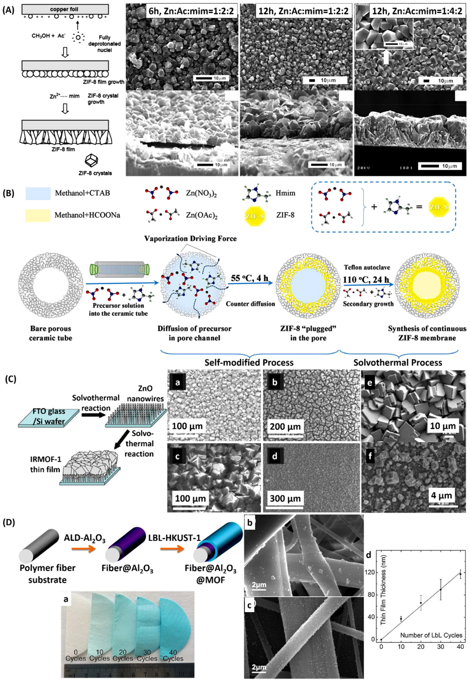
Inorganic seed-assisted secondary growth relies on preformed nano-sized metal-based seeds to assist the nucleation of MOF-TFs. One type of inorganic-involving seed is preformed MOF NCs. Bux et al. [100] fabricated a highly oriented ZIF-8 film via seed-assisted secondary growth. ZIF-8 NCs were prepared on a porous α-Al2O3 substrate via the hydrogen bonds formed with polyethyleneimine, which worked as the coupling agent between the ZIF-8 seeds and Al2O3 surface. The ZIF-8-seeded substrate was obtained after it was immersed in seeding solution using an automatic dip-coating device with defined dipping and withdrawing speeds, followed by traditional solvothermal synthesis to achieve continuous and well-intergrown ZIF-8 TF. XRD analysis of the resulting film showed a preferred orientation at the [100] direction parallel to the support that was explained by an evolutionary growth process. The resulting mesoporous and microporous structure showed excellent performance in H2/C3H8 separation, with a separation factor above 300. Papporello et al. [101] demonstrated the fabrication of ZIF-8 TFs on copper-based substrates, in which the commercially available ZIF-8 NCs were attached to copper foils as seeds via a manual rubbing manner (Figure 3A). It was observed that when using methanol as the precursor solvent, the presence of acetate would promote the precursor–substrate interactions, resulting in the formation of continuous, uniform, and adherent ZIF-8 TFs on copper foils. The resulting ZIF-8 TFs showed two orientations at the [110] and [211] directions and exhibited excellent mechanical and thermal stabilities. Sun et al. [102] fabricated high-quality MOF-TFs on α-Al2O3 ceramic tubes via a seed-assisted secondary growth strategy, in which the seeds were prepared via a solvent-vaporization driving force (Figure 3B). The ZIF-8 seeds were ready on the ceramic tube by pouring a stable precursor solution mixture of ZIF-8 into them and then sealing them inside the tube with a rubber stopper. The seeds then underwent heating at 55 °C for 4 h to react, at 55 °C for 1 h for drying, and at 25 °C for 12 h for washing. Then, the seeded ceramic tube was subjected to traditional solvothermal synthesis at 110 °C for 24 h to achieve a continuous ZIF-8 TF in the inner skin of the tube, which could be of interest for gas separation.
Another type of inorganic seeds is based on metal oxide nanostructures, such as NPs and nanowires (NWs). Abdollahian et al. [103] reported the fabrication of different IRMOF-TFs on ZnO NW-functionalized indium tin oxide (ITO) glass substrates, including glass, indium tin oxide (ITO) glass, and Si wafer (Figure 3C). ZnO NWs were grown on the substrate via a traditional solvothermal synthesis before immersion in each IRMOF precursor solution. The resulting IRMOF-TFs obtained high crystallinity after 20–24 h of secondary growth, showing a preferred out-of-plane orientation depending on the type of IRMOFs and acquiring μm-level thickness. All the IRMOF-TFs displayed an average thickness that was about 25 μm and exhibited similar morphology. In this study, the microwave-assisted synthesis showed its advantage in shortening the reaction time to 10 min for IRMOF-1 TF, which achieved about 1 μm in thickness. However, it was observed that the film morphology and crystallinity may be compromised by the rapid crystallization process as shown in the SEM images in Figure 3C,E,F. Furthermore, it was discovered that the metal oxide-based seeding layer does not necessarily contain the same metal species as that in the desired MOF-TFs. Zhao et al. [104] prepared Al2O3 seeding layers on polymer fibers via an ALD process to assist the nucleation and growth of copper-based HKUST-1 TFs (Figure 3D). Uniform HKUST-1 TFs were achieved on ALD-Al2O3-coated PP fibers via the LBL deposition strategy, by dipping the fibers in precursor solutions and solvent sequentially. A thorough rinsing by the solvent was necessary after each dipping in metal and organic precursors, respectively, to ensure complete removal of the unreacted precursors and unattached nuclei. Based on an HKUST-1 TF prepared by 40 LBL cycles in this study, the N2 adsorption BET surface area could reach 535 m2/gMOF (93.6 m2/gMOF+fiber), and high dynamic loadings for NH3 (1.37 molNH3/kgMOF+fiber) and H2S (1.49 molH2S/kgMOF+fiber).
3.3. Layer-by-Layer Deposition
Although the traditional hydro/solvothermal synthesis is a classic synthesis strategy to obtain MOF-TFs, many obstacles remain in its development, such as the difficulty in controlling the fabrication process that may result in uncontrollable film thickness and discontinuous film formation, and the high cost from large reactant consumption and waste production that limits its application [81]. There are many existing synthetic strategies to address these challenges; the LBL deposition strategy shows excellent control in film thickness [105,106] and surface roughness [104].
In contrast to the traditional one-pot hydro/solvothermal synthesis, the solutions for metal and organic precursors are held separately in LBL deposition of MOF-TFs, and the substrate is placed in each precursor solution sequentially, leading the fabrication of MOF-TFs by depositing alternating layers of oppositely charged precursor species (i.e., the metal cations and the deprotonated organic linkers). The detailed synthesis conditions for different types of MOF-TFs may vary. The LBL deposition strategy is favorable for the fabrication of oriented and well-defined MOF-TFs, in particular for surface-mounted metal-organic frameworks (SURMOFs) [107]. Wang and Wöll [108] published an excellent review in 2019 about the fabrication methods of SURMOFs via programmed LBL assembly techniques, depicting the broad application of the LBL deposition strategy in the preparation of MOF-TFs.
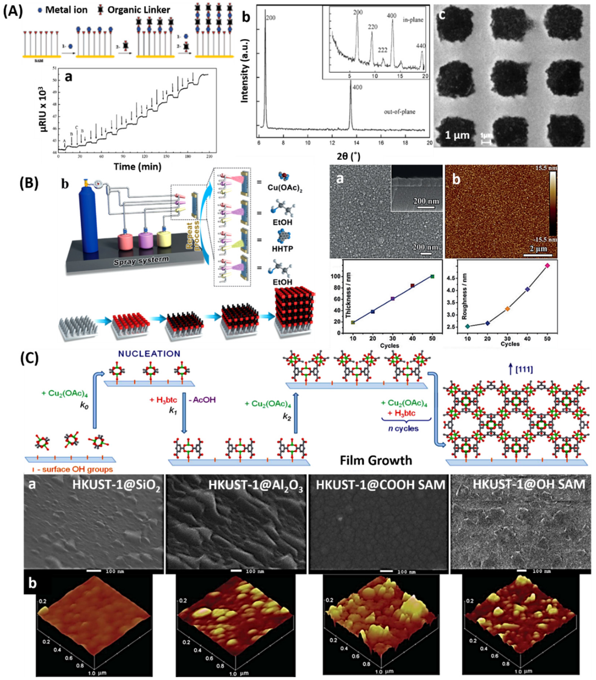
Shekhah et al. [107] established a stepwise LBL deposition route for the fabrication of MOF-TFs (Figure 4A). Gold substrate was functionalized by MHDA, resulting in a COOH-terminated surface for the secondary growth of HKUST-1 TFs. The modified substrates were immersed in 1 mmol/L ethanolic solution of Cu(CH3COO)2 for 30 min, and 1 h in 1 mmol/L ethanolic solution of 1,3,5- benzenetricarboxylic acid, with a rinse between each immersion. Highly oriented HKUST-1 TFs showing the [100] growth direction were deposited on COOH-terminated SAMs on gold substrates. Shekhah et al. [109] also implemented LBL deposition in the fabrication of MOF-TFs on porous substrates. Crystalline and homogeneous HKUST-1 and ZIF-8 TFs were achieved on a confined surface of mesoporous SiO2 foams, showing the potential of the LBL deposition strategy in controlling and directing the fabrication of MOF-TFs. Yao et al. [110] developed a spray-LBL deposition strategy to fabricate MOF-TFs (Figure 4B). The metal and organic precursor solutions for Cu3(HHTP)2, where HHTP = 2,3,6,7,10,11-hexahydroxytriphenylene, were sprayed on the substrate surface alternately to obtain the Cu3(HHTP)2 MOF-TFs. Like the traditional LBL strategy, the number of deposition layers can be facilely controlled by the spraying times. A good control over the film thickness was achieved, with a thickness increment of about 2 nm per spraying cycle. The performance in NH3 room-temperature sensing was tested based on a 20-nm thick Cu3(HHTP)2 TF, which reached a limit of detection that was 100 ppm. Other than planar substrates, uniform MOF-TFs can also be fabricated on different types of substrates via the LBL deposition strategy [104], which also presents excellent control over the film thickness. As mentioned in the section of secondary growth, MOF-TFs designed on QCM substrates often rely on functional SAMs to assist fabrication via the LBL deposition strategy as it offers a simple fabrication process and high growth rates and realizes uniform and oriented MOF-TFs with controllable thicknesses and chemical compositions [107,111,112,113]. Stavila et al. [114] systematically studied the formation process of HKUST-1 TFs on QCM electrodes assisted by the LBL liquid-phase epitaxy (LPE) (Figure 4C). Wannapaiboon et al. [51] developed a direct fabrication strategy of MOF-TFs, with the hierarchical structure on the surface of QCM sensors, via an LBL-LPE process, which allows the adsorption performances of the heterostructures to probe in real time. Other than planar substrates, the fabrication of uniform and continuous MOF-TFs can also be made on arched surfaces, such as optical fibers [42], via the LBL deposition manner.
Overall, the LBL deposition strategy can realize the fabrication of many types of MOF-TFs and enable precise control of the amount and location/distribution of functionalities for tailored properties, presenting a huge potential to extend the already considerable flexibility of MOFs. This synthesis strategy also provides a pathway to better understand the heterogeneous nucleation and growth of MOF-TFs [57], offers good control of the film thickness, gives rise to highly oriented and uniform TFs, and enables the fabrication of more complex MOF heterostructures [115,116,117]. However, this type of synthesis strategy is limited to the fabrication of specific types of MOF-TFs and is only available on solid supports [118], which restricts its application.
3.4. Dip-Coating Deposition
Dip coating (DC) is a simple, low-cost, and reproducible method for fabricating TFs and is extensively used in industries. This method is also applicable in the fabrication of MOF-TFs based on a colloidal suspension of MOFs NCs [119,120]. In this synthesis strategy, the metal and organic precursor solutions are well mixed to form a uniform colloidal suspension, in which a substrate is put in place to obtain an MOF-TF. Subjected to the continuous growth of MOF crystals in the suspension, the precursor solution mixture needs to be replaced after a certain time to ensure a high enough concentration of reactants for film growth. The reaction time for different MOFs varies depending on the reaction conditions. The DC technique can also be implemented in an LBL deposition manner, where the thickness of MOF-TFs can be controlled by modifying the immersing time, the number of dipping cycles, and the withdrawing speed [121].
Horcajada et al. [122] developed a colloidal route for the fabrication of MOF-TFs on Si wafers via DC deposition. In the fabrication of MIL-89 (Fe3O(CH3OH)3[O2C-(CH)4-CO2]3Cl(CH3OH)6) MOF-TFs, a colloidal solution iron(III) acetate and muconic acid in ethanol was prepared first by heating up the mixture solution at 60 °C for 10 min to promote the formation of colloidal particles. Each deposition cycle contained 2 min for immersion before the withdrawal with a speed of 4 mm/s at 15% relative humidity. After each cycle, the TF was washed with ethanol and dried either at room temperature or at 130 °C in air for 5 min. Flexible and uniform MIL-89 MOF-TFs were obtained (Figure 5A) under a consistent growth rate of 40 nm/coating. Then, Lu and Hupp [123] implemented DC deposition in the fabrication of ZIF-8 TFs. Highly oriented and continuous ZIF-8 TFs were achieved directly on glass slides and Si wafers (Figure 5B). The controllable synthesis showed a linear growth rate of ZIF-8 TFs of 100 nm/coating (30 min/cycle) and presented a thickness-dependent color-changing property that was interesting in optics. The DC deposition strategy is used extensively to fabricate various MOF-TFs that are of interest in electronics and optics [16,43,121,122,123,124].
3.5. Spin-Coating Deposition
Spin coating (SC) is a commonly used method to apply a uniform TF onto a flat solid substrate, which is also applicable for the fabrication of MOF-TFs. In a typical process of making MOF-TFs via the SC method, different precursor solutions for MOFs are dropped on the center of a flat substrate on a spinning object, which is set to a certain spinning speed and time, and the volume/concentration of the solutions are controlled to achieve a uniform distribution of precursor on the substrate surface [121].
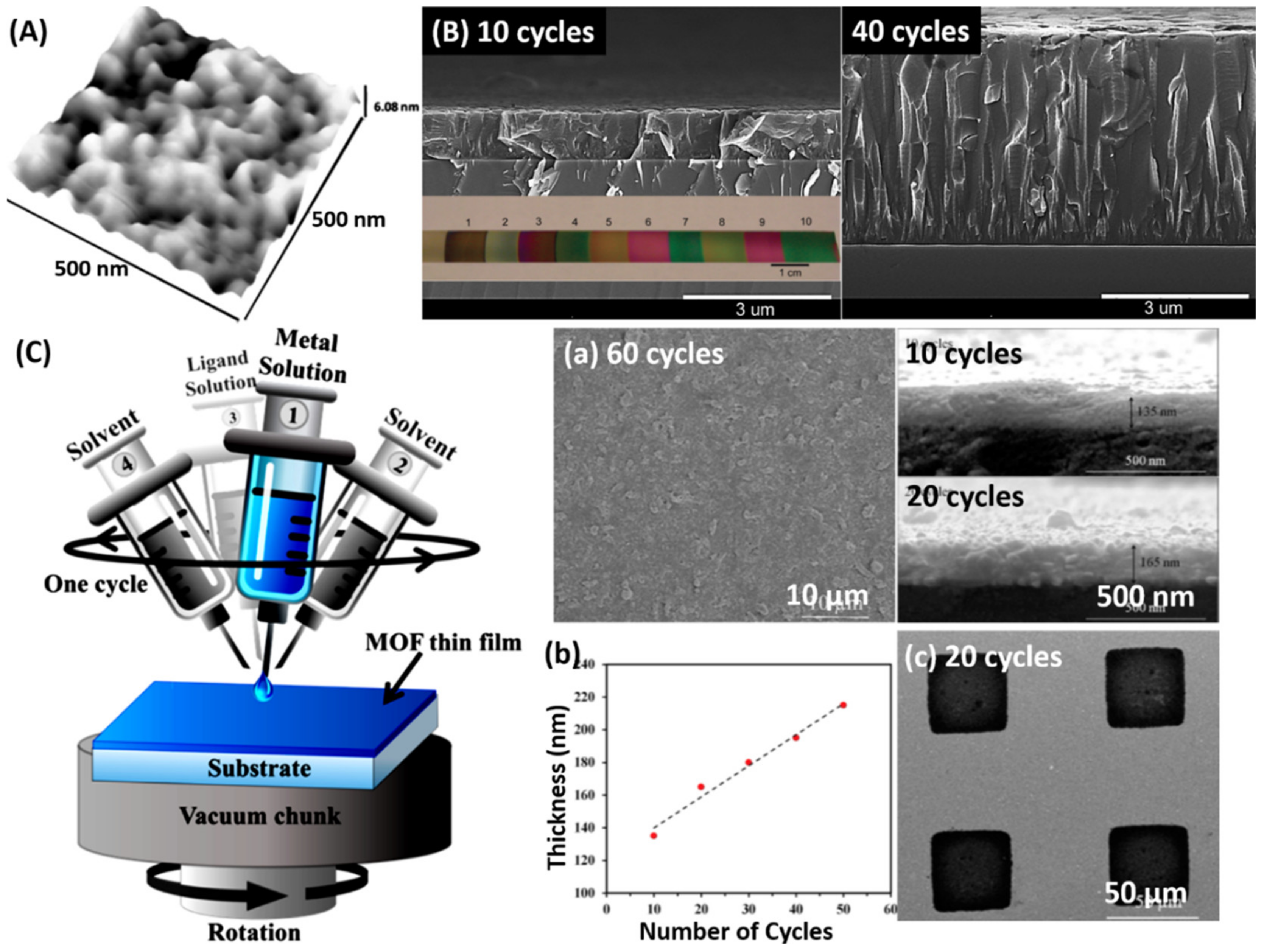
Chernikova et al. [125] proposed an LBL assembly strategy via an SC process, which realized the fabrication of smooth MOF-TFs in a relatively short time (Figure 5C). In this fabrication process, a spin coater was equipped with four micro-syringes containing the precursor solutions and solvents separately. First, the metal precursor solution was applied to the spinning substrate by one syringe. After it was uniformly distributed, the solvent was applied using another syringe to rinse the substrate surface. These two steps were repeated to achieve the coating of the organic precursor solution. The spinning time was 5 s for each solution and 8–10 s for each solvent depending on the type of MOFs. For each step, only 50 μL of liquid was used. The four steps finished one cycle of SC deposition. One can increase the thickness of MOF-TFs through multiple cycles. Different MOF-TFs, such as HKUST-1, ZIF-8, Cu2(BDC)2, and Zn2(BDC)2, were achieved via SC deposition. In this study, a Cu2(BDC)2 TF obtained a thickness of about 140 nm for 10 cycles. Moreover, it was found that the time needed to finish 100 cycles was only 50 min, which was significantly shorter in comparison to the 25 h needed in the conventional LBL deposition process. This strategy is extendable to the fabrication of other MOF structures, such as hybrid MMMs [126].
The SC technique can achieve MOF-TFs in a short time with low reactant consumption, and the resulting MOF-TFs can be dense and uniform, with thicknesses that can range from the micron to nano-scale [125]. However, it is appreciable that this method could cause crystal defects, and results in structural defects in MOF-TFs [121].
3.6. Interfacial Synthesis
The interface synthesis of MOF-TFs can be realized at the interface between two immiscible media, such as oil and water or air and water, which could result in the formation of freestanding MOF-TFs.
The interfacial synthesis could occur at a liquid–liquid interface, where the metal and organic precursors are dissolved in two immiscible solvents separately. Ameloot et al. [80] reported the first demonstration of liquid–liquid interfacial synthesis for MOF-TFs. The coordination of Cu2+ cations and BTC3- linkers happened at the interface of an aqueous solution containing the metal precursor and an organic solution containing the organic precursor, thus resulting in a freestanding and uniform HKUST-1 TF at the interface. Other types of MOF-TFs, such as ZIF-8 TFs [127], can also be obtained through this type of synthesis strategy.
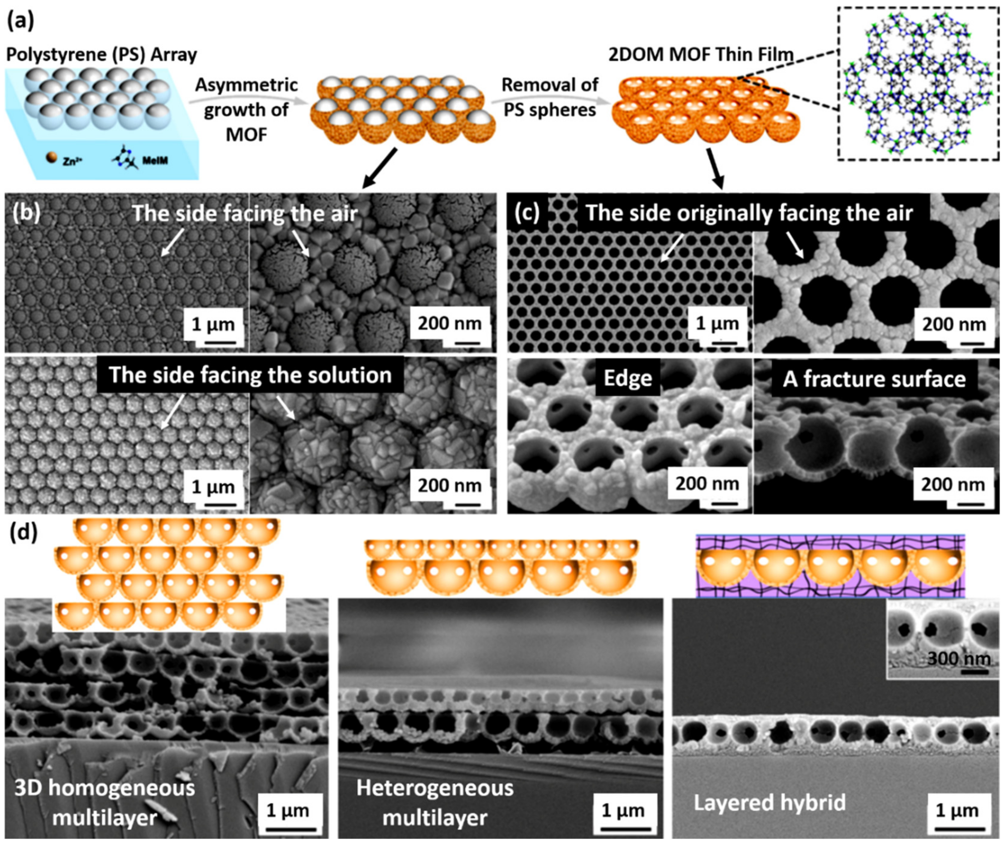
Other than the synthesis at the interface of two immiscible liquids, there is an air–liquid interfacial synthesis for MOF-TFs. Li et al. [128] developed a fabrication strategy of MOF-TFs, patterns, and layered structures (including hybrid layers) via a templated air–liquid interfacial synthesis strategy (Figure 6). The resulting ZIF-8 TFs obtained hierarchical structures through close-packed arrays of colloidal spheres floating at the air–solution interface, which demonstrated different physical properties from unstructured TFs. The obtained 2D-ordered macroporous (2DOM) ZIF-8 TF-loaded polyvinylidene fluoride (PVDF) membrane showed a much improved experimental separation factor, 3.33, for methyl blue and methyl orange in comparison with pristine PVDF (1.64) and unstructured ZIF-8 TF-loaded PVDF (3.01). Other than adsorption and separation, this well-organized superstructure was also of interest in catalysis and microreactors. This method introduced a facile fabrication of multicomponent devices and could readily extend to other types of templates and MOFs.
3.7. Contra-Diffusion Synthesis
Although many strategies have been developed to achieve a high rate of heterogeneous nucleation of MOFs on substrates, they often complicate the process [60,129,130]. Therefore, a contra-diffusion synthesis strategy was developed to realize an efficient way for the fabrication of MOF-TFs. The contra-diffusion synthesis is similar to the interfacial synthesis of MOF-TFs in that the metal and organic precursor solutions are placed separately. However, a contra-diffusion synthesis requires porous substrates [131,132,133,134,135] whereas the interfacial synthesis could proceed without one [127]. In the contra-diffusion synthesis, the substrate separates the two precursor solutions. The precursors diffuse in opposite directions through the substrate, and MOFs can form upon encountering the precursors. The contra-diffusion synthesis is capable of making MOF-TFs that are embedded into the porous substrates, resulting in a strong adhesion between MOF-TFs and substrates. Although it exhibits simplicity and good reproducibility, the contra-diffusion synthesis strategy is limited to MOF-TFs with high permeability and is only achievable on porous substrates, which limits its application.
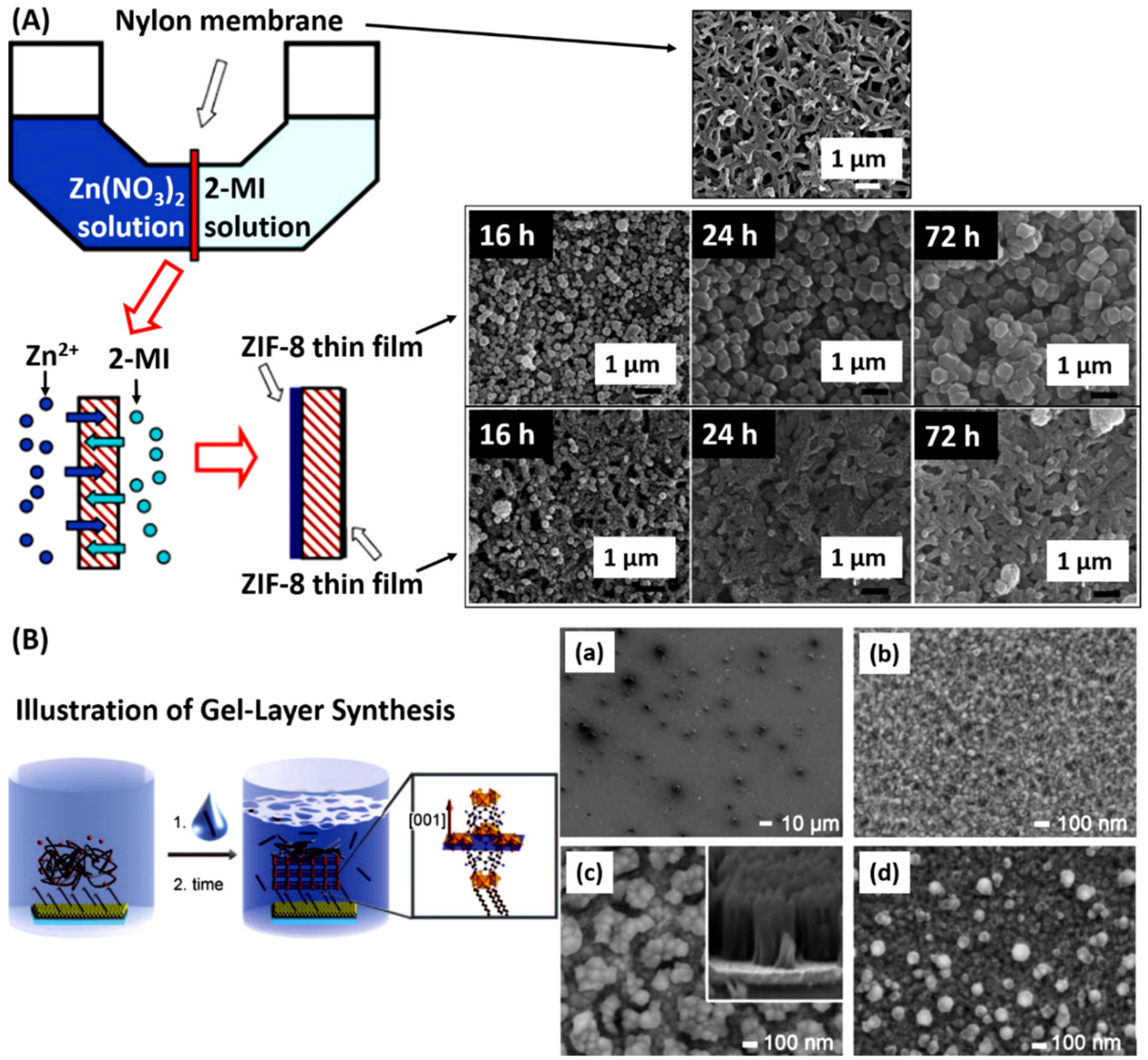
Yao et al. [133] developed a synthesis strategy to fabricate ZIF-8 TFs on flexible substrates via a contra-diffusion strategy (Figure 7A). Two precursor solutions containing Zn2+ and 2-mIm, respectively, diffused from opposite sides of porous nylon substrate in opposite directions, and ZIF-8 TFs were formed on both sides of the substrate. In this type of synthesis, ZIF-8 TFs revealed different morphologies on two sides of the nylon substrate, which could arise from different local molar ratios of 2-mIm/Zn2+, where large crystals with sizes of 0.2–5 μm formed on the Zn2+ side and small NCs formed on the 2-mIm side as shown by the SEM images in Figure 7A. After crystallization at room temperature for 72 h, the surficial ZIF-8 film could reach 16 μm at the Zn2+ side, which exhibited a H2/N2 ideal selectivity of 4.3 with H2 permeance of 1.97 × 10⁻⁶ mol/m2sPa and N2 permeance of 0.46 × 10⁻⁶ mol/m2sPa. One can control the coverage of the porous substrate and the thickness of MOF-TFs by tuning the reaction time and the metal/linker concentration ratio in the reaction system [92].
3.8. Gel-Layer Synthesis
Schoedel et al. [136] developed a gel-layer strategy for the fabrication of MOF-TFs (Figure 7B). In this method, thin poly(ethylene oxide) or poly(ethylene glycol) gel layers hold a high concentration of metal precursors near SAM-coated gold substrates. Following the diffusion of organic linkers through the metal-containing gel, heterogeneous nucleation of MOFs occurs at the gel–SAM interface. Both rigid HKUST-1 TFs and flexible Fe-MIL-88B-NH2 TFs were successfully fabricated on SAM-coated gold substrates after 96 h of reaction at room temperature. The resulting Fe-MIL-88B-NH2 TFs were homogeneous and showed a preferred orientation at the [001] direction based on the COOH-terminated SAMs; however, the HKUST-1 TFs did not. As shown by the SEM images in Figure 7B, the resulting thickness of Fe-MIL-88B-NH2 TFs was 500–550 nm, consisting of small islands of crystals with several hundred nm in diameter, of which the gaps between islands were about 100 nm. There was also a very homogeneous layer at the bottom, of which the thickness was about 40 nm.
The gel-layer synthesis method can realize the conservation of a high concentration of reactants to be employed in heterogeneous film formation and eliminates the necessary precondition of traditional hydro/solvothermal precursor solutions. The molecular weight of the polymer (gel) and the concentration of metal precursors in the gels are the keys to control the morphology and thickness of the resulting MOF-TFs. This method is pictured to be widely applicable with suitable gel matrices, yet it could be very time-consuming, depending on the types of MOFs and gel matrices.
3.9. Evaporation Method
The evaporation method is an effective way to synthesize MOF-TFs with a controllable scale via an evaporation-induced crystallization process [137,138]. In this synthesis strategy, a clear and stable precursor solution is prepared without small MOF nuclei. Following the removal of the solvent by slow evaporation, there is crystallization that leads to the formation of MOF crystals locally on the substrate. This method can achieve a precise localization of MOF crystals on solid substrates.
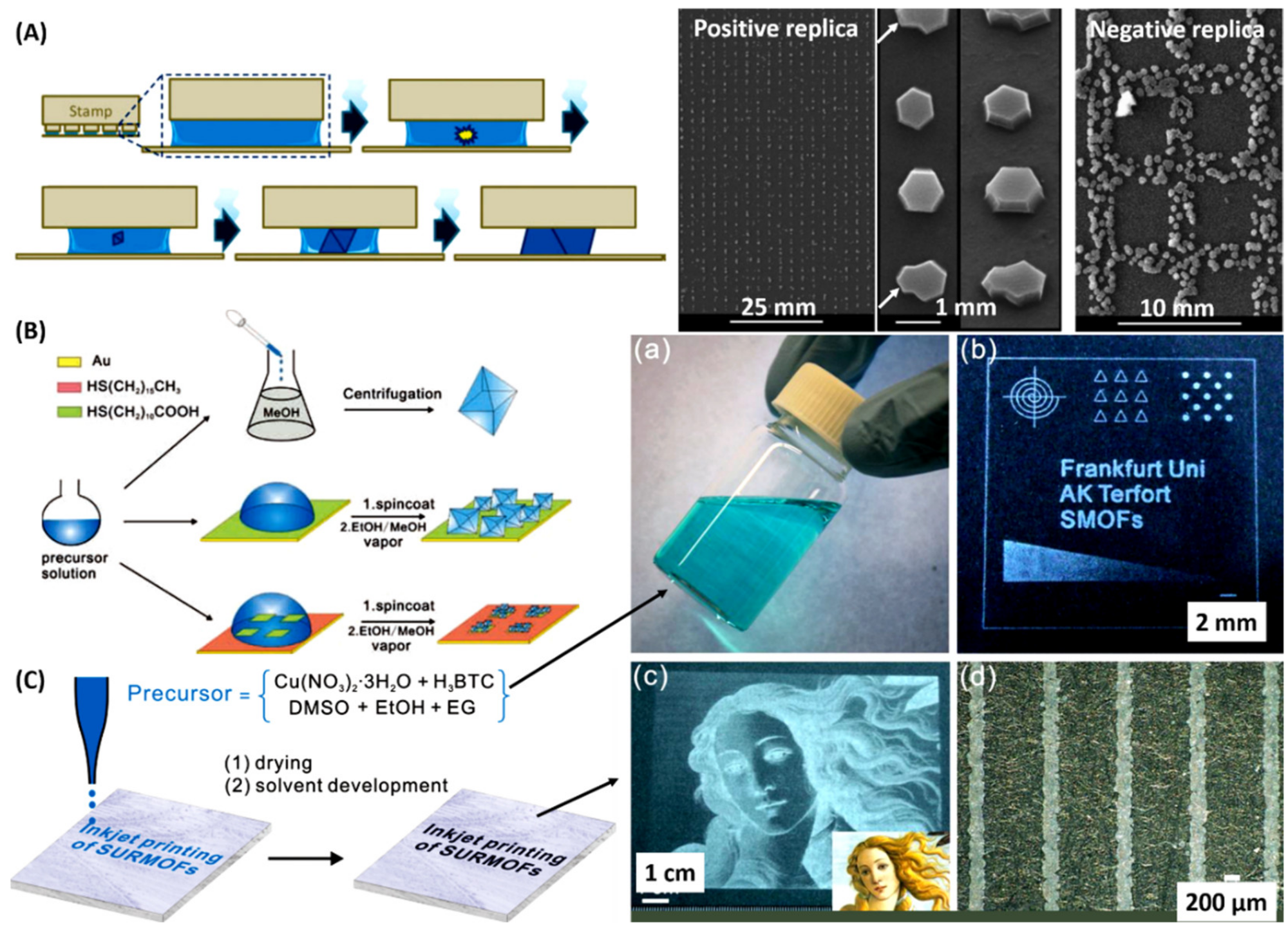
Ameloot et al. [137] reported the fabrication of HKUST-1, MOF-5, and ZIF-8 patterned TFs via the evaporation method in a stamping manner (Figure 8A). The precursor solution of each type of MOFs was prepared as in conventional solvothermal synthesis. Patterning was performed by placing stamps inked with the precursor solution on a glass substrate. In this method, the stamps were removed after solvent evaporation. Unlike conventional secondary growth based on SAMs, the resulting HKUST-1 crystals in this study showed [111] growth orientation regardless of the substrate surface termination (i.e., silanol, vinyl, and carboxylic acid groups). It was suggested by the authors that the confinement between the stamp and the substrate during in situ crystallization had a more significant influence on the preferred orientation of the resulting MOF-TFs than the substrate surface chemistry. It was observed that the roughness of all films obtained via the evaporation method appeared high. Zhuang et al. [138] reported the fabrication of HKUST-1 TFs on rigid substrates at room temperature via an evaporation process (Figure 8B), and then they implemented this method with an inkjet-printing technique and achieved patterned MOFs on flexible substrates as shown in Figure 8C [139]. The evaporation method could also be applied with the drop-casting method to make MOF-TFs [140]. Other types of MOF-TFs, such as ZIF-7 (Zn(bIm)2) [141], are also achievable via fast evaporation of the solvent.
These contributions demonstrate the potential of the evaporation method in placing MOFs in various microprinting and nanotechnological fields and that faster solvent evaporation could produce more defective and less stable films compared to the controlled release of solvent in a traditional process [142], whereas the films could potentially enhance gas permeation [126].
4. General Liquid–Solid Synthesis
Although the liquid–liquid synthesis strategies have been extensively studied and widely used in the fabrication of MOF-TFs, the limited scalability of these solution-based approaches prevent their large-scale production. Many other synthesis strategies were developed to realize a more economical and greener process. The liquid–solid reaction, one of the alternatives, can significantly promote heterogeneous nucleation and growth of MOF-TFs on substrates.
4.1. Electrochemical Deposition
Electrochemical deposition (ECD) is one emerging synthesis strategy conducted in the fabrication of MOF-TFs, as discussed in many excellent reviews [72,118,143]. In a classic ECD system for MOF-TF deposition, there is a two-electrode cell (a three-electrode cell is also available) containing metals, organic linkers, and electrolytes, and the MOF-TF is formed on the electrode(s) via the coordination of metal ions with deprotonated organic ligands near the electrode surface through anodic dissolution [144,145,146], cathode reduction [147,148], or charge driving [149,150]. This type of synthesis strategy allows for the fabrication of MOF-TFs with controllable thicknesses via real-time monitoring of the amount of passed charge. Moreover, the electrochemical nature of this process offers an in situ repairing of defects, such as cracks and pinholes. However, this method is limited to the fabrication of non-conductive MOF-TFs on conductive substrates, which restricts its application. Besides, metal ions with high inertness could separate on the cathode, and the organic linkers may be oxidized.
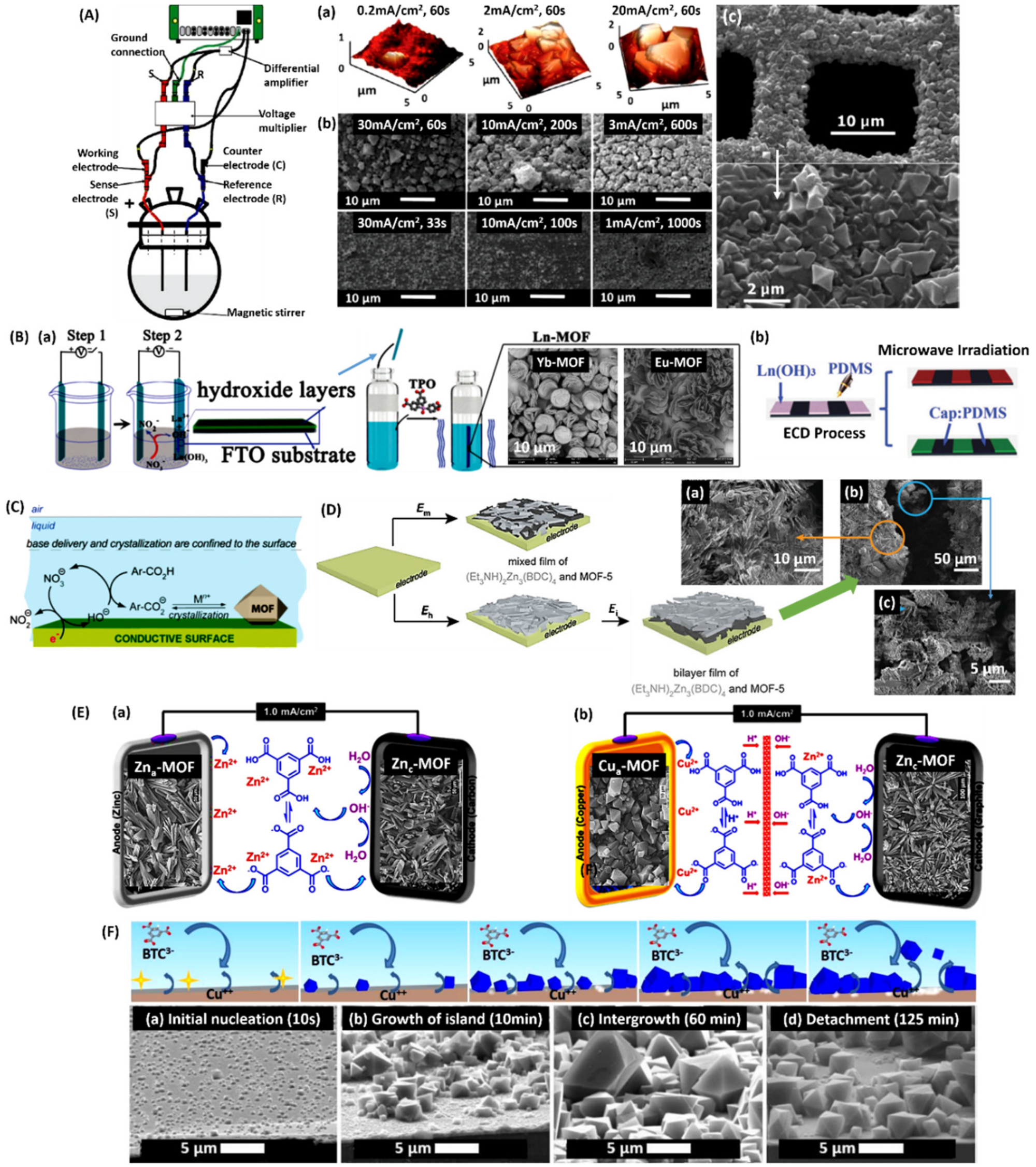
Anodic electrodeposition (AED) that is based on the dissolution of metal components is the method of choice for large-scale production of some commercially available MOFs because of its scalability, ease of processing, and low working temperature. Joaristi et al. [151] reported the fabrication of several archetypical MOF-TFs via anodic dissolution in an electrochemical cell (Figure 9A). The anode was a metal plate (highly pure Zn, Cu, or Al), and the cathode was preferable inter alia (i.e., Zn-Zn, Cu-Cu, and Al-Al), while graphite and steel were also available. MOF-TFs, including HKUST-1, ZIF-8, MIL-100(Al) (Al3O(H2O)2(BTC)2X, X = OH or F), and MIL-53(Al) (Al(OH)[O2C-C6H4-CO2]), were obtained via AED in an electrodeposition cell containing proper organic linkers. Take the fabrication of HKUST-1 TFs as an example. A linker solution was prepared by dissolving BTC and tributylmethylammonium methyl sulfate in 96 vol % ethanol. The solution was heated up to 80 °C in the electrochemical cell with two copper electrodes spaced at least 3 cm apart. Then, 50 mA was passed through the system for 1 h. The product was filtered off and cleaned with ethanol at room temperature overnight, then filtered again and dried at 100 °C. An average of ∼100 mg of dried HKUST-1 was obtained from each synthesis. As shown in Figure 9Ac, HKUST-1 TFs covered the entire copper mesh. The deposition conditions, such as linker solubility, temperature, and current density, could be adjusted to obtain the best morphology, coverage, and crystallinity for the resulting MOF-TFs. Compared to traditional hydro/solvothermal synthesis, ECD-based synthesis strategies showed advantages in reducing the reaction time and temperature in this study. AED is also accessible in the fabrication of MOF-TFs on other types of conductive substrates. Hauser et al. [152] fabricate MOF-TFs on ITO glass. First, copper or zinc microcrystalline films (Cu-ITO and Zn-ITO) were deposited electrochemically on ITO electrodes in aqueous/ethanol salt solutions serving as the metal source in anodic dissolution. Several well-adhered and homogeneous MOF-TFs, including HKUST-1, Cu(C10H8N2)Br2, Zn-BTC (Zn3BTC2), and Zn2BPDC (where BPDC = 2,2′-bipyridine-5,5′-dicarboxylate), were obtained on ITO anodes under the deposition conditions in this study. HKUST-1 TFs can be achieved on copper-coated QCMs via the AED strategy as well [144]. While most MOF-TFs can be deposited using metal or a metal-coated electrode, it is difficult and expensive to electrochemically deposit rare earth metals as the electrodes for the fabrication of luminescent MOF (LMOF)-TFs. Li et al. [145] developed a microwave-assisted electrochemical deposition strategy for LMOF-TFs (Figure 9B). In this study, a dense and homogeneous Ln(OH)3 (Ln = Eu, and Tb) layer was first deposited on a fluorine-doped tin oxide (FTO) electrode after eight cycles of ECD in a cell containing Ln(NO3)3. Subsequently, the Ln(OH)3 layer was converted to Ln-MOF TFs under microwave irradiation in a cell containing TPO linkers, where TPO = tris-4-carboxylatephenyl phosphineoxide. Patterned Ln-MOF TFs were also made using this microwave-assisted ECD strategy by patterning poly(dimethylsiloxane) (PDMS) films on FTO glass. These patterned TFs had strong luminescence properties, which is of interest in the fields of color displays, luminescent sensors, anti-counterfeiting barcodes, and structural probes. In summary, in the AED strategy for MOF-TFs, the electrode acts as the cation source, and there are blocking-free pores and easily controlled metal oxidation states. However, corrosion of the anode is inevitable during the AED process, and there are restrictions on the anode material selection and single-phase MOF conformation.
Cathodic generated –OH groups can promote the deprotonation of organic linkers in the typical cathodic electrodeposition (CED) process. At the same time, metal ions move to the surface of the cathode and lead to the formation of MOF-TFs locally on the cathode. Li et al. [147] established the CED for the fabrication of crystalline MOF-TFs directly on conductive surfaces (Figure 9C). In this study, a substantial amount of –OH groups were generated and accumulated near the surface of the FTO electrode, which promoted the nucleation and growth of MOF-5 TFs exclusively onto the conductive FTO glass. Then, they demonstrated the fabrication of multiphasic and multilayered MOF-TFs via the same synthesis strategy (Figure 9D) [148]. In this CED experiment, the electrolyte solution was prepared by dissolving tetrabutylammonium hexafluorophosphate in DMF and stored in a sealed bottle in a nitrogen-filled glovebox. A typical deposition solution in this study consisted of 100 mmol/L Et3NHCl, 100 mmol/L Zn(NO3)2, and 50 mmol/L H2BDC. A bilayer film consisting of two different types of MOFs was obtained; this method offers a potential path to large-scale fabrication of heterostructured, multiphasic, and multilayered MOF-TFs. In contrast to the AED, the CED allows for the free choice of electrode material, in situ deprotonations of organic linkers, and multiphasic MOF-TF fabrication. However, this method is limited by possible metal reduction and pore blocking.
Paired electrodeposition (PED), which involves the pairing of both AED and CED strategies in the fabrication of MOF-TFs on both electrodes, is a newly developed strategy that realizes green synthesis of MOF-TFs based on the traditional ECD. Alizadeh et al. [153] developed convergent and divergent PEDs (CPED and DPED, respectively) for the simultaneous fabrication of MOF-TFs on both electrodes (Figure 9E). In the CPED, Zn-BTC MOF-TFs were obtained on both the zinc anode and carbon cathode. In the DPED, since they share the same type of organic linker, Zn-BTC and HKUST-1 TFs were obtained on the graphite cathode and copper anode, respectively. Take the fabrication of Zna/Znc-MOF-TFs as an example. To achieve CPED, both metal salt and metal were used as two cation sources, in which Zn(NO3)2 for CED and Zn metal as a sacrificial anode to generate Zn2+ cations for AED. Zn(NO3)2 as a cation source and NaNO3 as a supporting electrolyte were dissolved in water (solution A, pH 2.1), and H3BTC in ethanol (solution B). The prepared solutions were aged under stirring for 2.5 h at room temperature. Then, the electrodeposition process was performed in a homemade undivided two-electrode cell with Zn plate and carbon plate as the electrodes. After applying 1 mA/cm2 for 3 h, complete coverage of Zna/Znc-MOF-TFs on the two electrodes was achieved, as shown in Figure 9Ea. This deposition strategy realized a current efficiency that was twice as much as the traditional methods, demonstrating a sustainable development for the fabrication of MOF-TFs using ECD.
Campagnol et al. [154] systematically investigated the fabrication mechanisms of MOF-TFs using ECD, including both AED and CED (Figure 9F). The proposed mechanism involved four phases: (I) Initial nucleation, (II) growth of MOF islands, (III) intergrowth, and (IV) crystal detachment. Hence, based on the understanding of the ECD mechanism, the metal used for the SBU needs to be carefully considered. For example, one could consider if the metal is noble or not, if it passivates or makes hydroxides. When these conditions are clear, the choice of AED or CED becomes easier. MOF-TFs (e.g., HKUST-1) can be made either way, although the resulting morphology can vary remarkably. Overall, the ECD strategies provide a roadmap for large-scale fabrication of MOF-TFs, including single-phase and heterostructured multiphasic and multilayered MOF-TFs and membranes.
4.2. Self-Sacrificing Templated Synthesis
MOF-TFs could be fabricated based on self-sacrificing solid templates consisting of metals, metal oxides, or hydroxides. In a general self-sacrificing templated synthesis, the template containing metal species of the desired MOF provides the metal cations for the formation of MOF-TFs, and meanwhile serves as the substrate, while the reaction solution provides only the organic linkers. In such a synthesis system, the formation of free MOF crystals in the liquid phase can be eliminated, and the fabrication of MOF-TFs on the template can be significantly promoted under optimal reaction conditions [155]. However, this reaction is limited by the dissolution of metal ions and may result in self-termination of the reaction when the MOF-TFs formed at the interface of the metal template and organic precursor solution becomes thick.
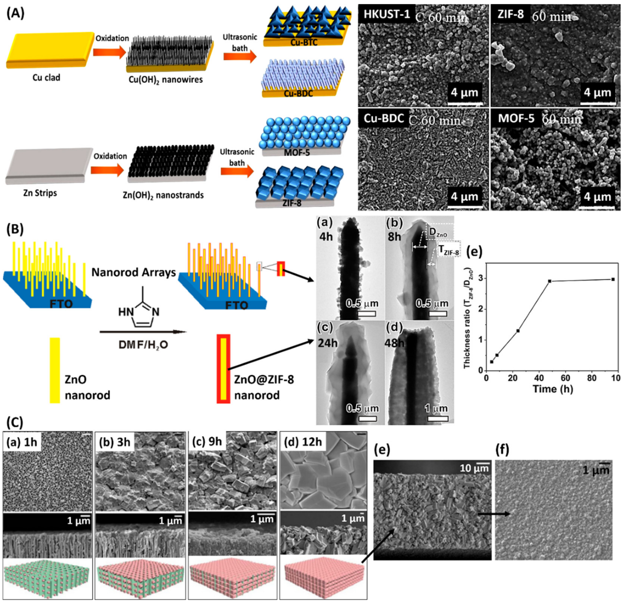
One type of self-sacrificing template consists of only metals. Zou et al. [156] reported a self-sacrificing templated fabrication for MOF-TFs using a single metal source. In this study, a Zn wafer was used as the template, which was first activated by H2O2 to form a hydroxide layer on the surface. The prepared Zn wafer was placed at the bottom of an autoclave filled with aqueous H3BTC solution. Zn-BTC MOF-TFs were obtained on top of the remaining Zn wafer via hydrothermal synthesis at 140 °C for 24 h. After being cleaned with distilled water and dried at 85 °C, the obtained TF was tested for chemical sensing based on the photoluminescence properties of Zn-BTC MOFs. In this study, the Zn-BTC MOF-TFs showed high sensitivity and selectivity towards dimethylamine. A limit of detection for dimethylamine of 8.57 ppm was identified. Other types of MOF-TFs, such as HKUST-1, ZIF-8, Cu-BDC, and MOF-5 [157] (Figure 10A), have also been achieved on proper metal templates via this synthesis strategy upon substrate surface activation. Kang et al. [158] developed a self-sacrificing templated fabrication using a single metal source without activation pretreatment. A nickel net was used as the nickel source and substrate to synthesize Ni-MOF-TFs. Highly crystalline and continuous Ni2(L-asp)2(bipy) (L-asp = L-aspartic acid; bipy = 4,40-bipyridine) MOF-TFs were then obtained locally on the nickel net via a traditional solvothermal synthesis at 150 °C after 48 h. The obtained mesoporous and microporous structure showed good separation results of (R)-2-methyl-2,4-pentanediol and (S)-2-methyl-2,4-pentanediol at high temperatures. When the operating temperature increased from 25 to 200 °C under 0.1 MPa, the permeance of R increased from 526 to 1047 g/m2h, while that of S only slightly increased from 406 to 533 g/m2h.
Another type of self-sacrificing template relies on metal oxides or hydroxides. Zhan et al. [159] reported the fabrication of ZIF-8 TFs based on ZnO templates (Figure 10B). By controlling the reaction conditions, ZnO@ZIF-8 core-shell nanorod (NR)/nanotube (NT)-structured TFs were obtained via traditional solvothermal synthesis at 70 °C for 24 h, where ZnO NRs/NTs served as the source of Zn2+ ions and as the template for ZIF-8 TFs. It was discovered that the solvent composition and reaction temperature are critical in this type of synthesis strategy since they can influence the dissolution rate of ZnO and the coordination rate of 2-mIm with the released Zn2+ ions. The ZnO@ZIF-8 core-shell structure showed different photocurrent responses for hole scavengers with various sizes, which was tested on H2O2 and ascorbic acid (AA). In the study, AA did not produce a similar enhancement effect to the photocurrent response like H2O2 because its molecule size is larger than the pore aperture of ZIF-8. Khaletskaya et al. [160] performed the fabrication of ZIF-8 TFs on QCMs via self-sacrificing synthesis. ZnO TFs were first prepared on the surface of QCM via ALD or magnetron sputtering, which resulted in different film morphologies for ZIF-8. The ZIF-8 TFs formed on sputtered ZnO templates showed no characteristic shape of ZIF-8 crystals and appeared larger than the one on the ALD-ZnO template, which was possibly due to the larger size of ZnO particles obtained by the sputtering process. The ZIF-8 TFs formed on ALD-ZnO templates showed a typical faceted shape of ZIF-8 crystals, which could result from the less dense and predominantly nanocrystalline ZnO precursor via ALD that provided a faster dissolution and conversion rate of the metal oxide. With either ZnO template, compact and homogeneous ZIF-8 TFs were obtained on both Si wafers and QCMs via microwave-assisted solvothermal synthesis at 80 °C for 1 h. In this study, highly oriented Al(OH)(NDC) MOF-TFs, where NDC = 1,4-naphthalenedicarboxylate, was achieved by using the same synthesis strategy. Mao et al. [161] reported the fabrication of HKUST-1 TFs on porous anodic aluminum oxide (AAO) substrates via a secondary growth based on Cu(OH)2 nanostrands (CHNs). A highly positively charged CHN TF was prepared by mixing the 2-aminoethanol solution with Cu(NO3)2 solution and aging at room temperature, followed by filtering onto the surface of porous AAO. Then, the prepared CHN@AAO substrate was immersed in the H3BTC solution for 1 h to obtain a thin layer of HKUST-1 crystals as the seeding layer to achieve HKUST-1 TF via secondary growth. After 24 h of reaction at 120 °C, dense HKUST-1 TF with a thickness of about 30 μm was obtained on the AAO substrates. This structure showed a high permeance of H2 at room temperature of 3.14 × 10⁻⁶ mol/m2sPa, which was higher than CH4, N2, O2, and CO2. It provided separation factors of the binary gases, i.e., H2/CH4, H2/N2, and H2/CO2, that were 5.1, 6.3, and 7.6, respectively, considering the values of the ideal Knudsen selectivities of 2.8, 3.7, and 4.7 for the corresponding binary gases. Freestanding MOF-TFs are also achievable through this type of synthesis strategy [162] (Figure 10C). The self-sacrificing templated synthesis strategy is also able to be employed with other types of synthesis strategies, which broadens its application in the fabrication of MOF-TFs. Schäfer et al. [163] fabricated MOF-TFs via the ECD through a self-sacrificing synthesis strategy. HKUST-1 TFs were obtained on copper foils only when surface oxide layers were present on the electrode. Furthermore, only Cu2O was found to be working in the formation of HKUST-1, not CuO. The hypothesis is that the active form of copper precursor for HKUST-1 in the ECD system was Cu2O from the oxidation of copper foil.
Metal oxides and hydroxides with high reactivity (i.e., they are easily ionized in solution) are preferable in this type of synthesis strategy, where the metal dissolution process is a crucial factor. Some commonly used metal oxides are Cu2O, ZnO, and Al2O3, and hydroxides Zn(OH)2, Cu(OH)2, Ni(OH)2, Ca(OH)2, Mg(OH)2, and Al(OH)3. Considering the diverse and accessible macro-, micro-, and nanomorphology of metal, metal oxides, and metal hydroxides, many MOF-TFs, patterns, and composite structures can be made via self-sacrificing templated synthesis based on a suitable metal source.
5. Other Types of General Synthesis
Although the previously reviewed fabrication techniques based on traditional solution-processing techniques have been extensively studied and widely used in the fabrication of MOF-TFs, the limited scalability of these solution-based approaches prevent their large-scale production. Several common disadvantages of the solvent-processing fabrication techniques for MOF-TFs are (1) the large amount of solution needed due to the low volumetric yield of TFs, (2) the difficulty in preventing the formation of bulk MOFs and controlling the waste generation, and (3) potential safety and processing issues when using solvents, especially under solvothermal conditions. Therefore, many other types of synthesis strategies have been developed to realize a more economical and greener process. In this section, we will review currently reported fabrication techniques based on the solid–solid synthesis, vapor–solid synthesis, vapor–gel synthesis, and the special post-assembly method.
5.1. Solid–Solid Synthesis
As a solution to overcome the difficulties of solution-processing techniques, fabricating MOF-TFs in a solvent-free manner becomes an emerging strategy that can realize green synthesis [164]. Employing metal oxides or hydroxides instead of typically conducted metal salts in the reaction with organic linkers eliminates the production of acids since this type of synthesis strategy involves simple acid-base neutralization with water as the only byproduct.
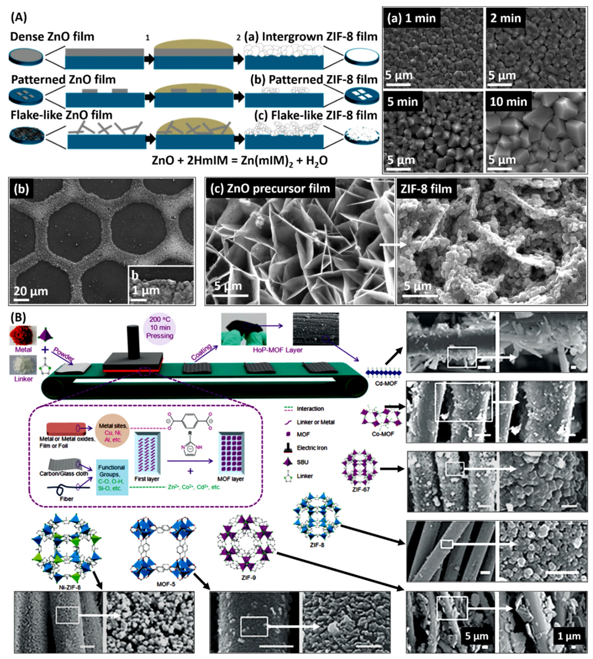
Stassen et al. [164] demonstrated the fabrication and patterning of ZIF-8 TFs via solvent-free synthesis through the reaction of ZnO with melted 2-mIm (Figure 11A). This study obtained a dense ZIF-8 TF on Si wafer by sputtering, a patterned ZnO TF by μCP, and a flake-like ZnO TF on a carbon steel support by ECD. After covering with a thin layer of finely ground 2-mIm powders, the conversion of ZnO to ZIF-8 was completed at 160 °C in an oven, which also allowed for the evaporation of byproduct that was water. The crystal growth can be controlled by tuning the reaction time and changing the amount of prepared ZnO. The resulting ZIF-8 TFs precisely follow the original morphology of the ZnO TFs. Therefore, based on many morphologies of metal oxide TFs that can be obtained on different substrates using various techniques, the solvent-free synthesis strategy provides an easy route to apply many types of MOF-TFs on integrated devices in electronics and optics. However, this strategy is only preferable for MOFs that consist of organic linkers with a low melting point.
Following the concept of solvent-free synthesis, Chen et al. [165] introduced a hot-pressing (HoP) synthesis strategy to fabricate MOF-TFs under binder-free and solvent-free conditions (Figure 11B). In a general HoP process, both metal and organic precursors of MOFs are placed on a substrate and are pressed by a heating source, such as an electric iron, where the applied heat triggers the reaction between the precursors and leads to the formation of MOF-TF on the substrate. Different MOF-TFs, including MOF-5, ZIF-8, ZIF-9 (Co(bIm)2), ZIF-67 (Co(2-mIm)2), Co-MOF (Co(dcIm)2, where dcIm = 4,5-dicyanoimidazole), Cd-MOF (Cd(Im)2, where Im = imidazole), and bimetallic Ni-ZIF-8, have been realized on various flexible substrates, including carbon cloth, AAO film, nickel foam, copper foil, glass cloth, and glass fiber, via the HoP strategy. Take the fabrication of ZIF-8 TFs on carbon cloth as an example. Zinc acetate, 2-mIm, and polyethylene glycol (PEG) were manually ground and mixed. The mixture was then loaded on a 2 cm × 2 cm carbon cloth, packed with aluminum foil, and heated with an electric heating plate at 200 °C for 10 min. After peeling off the aluminum foil, the TF was washed with ethanol and DMF (each for 1 h) and stored in ethanol. All the ZIF-8 TFs obtained on different substrates presented uniformly distributed crystals. The HoP strategy can realize the fabrication of MOF-TFs on flexible materials with a controllable scale, which could be of interest in flexible electronics. However, this method requires high thermal stability of the MOFs and substrates.
5.2. Vapor–Solid Synthesis
A vapor–solid synthesis method is promising to apply MOF-TFs on devices that are incompatible with wet-based processing due to the risk of corrosion and contamination. There are several ways to achieve the fabrication of MOF-TFs in a vapor–solid synthesis manner, such as atomic layer deposition (ALD), chemical vapor deposition (CVD), and physical vapor deposition (PVD).
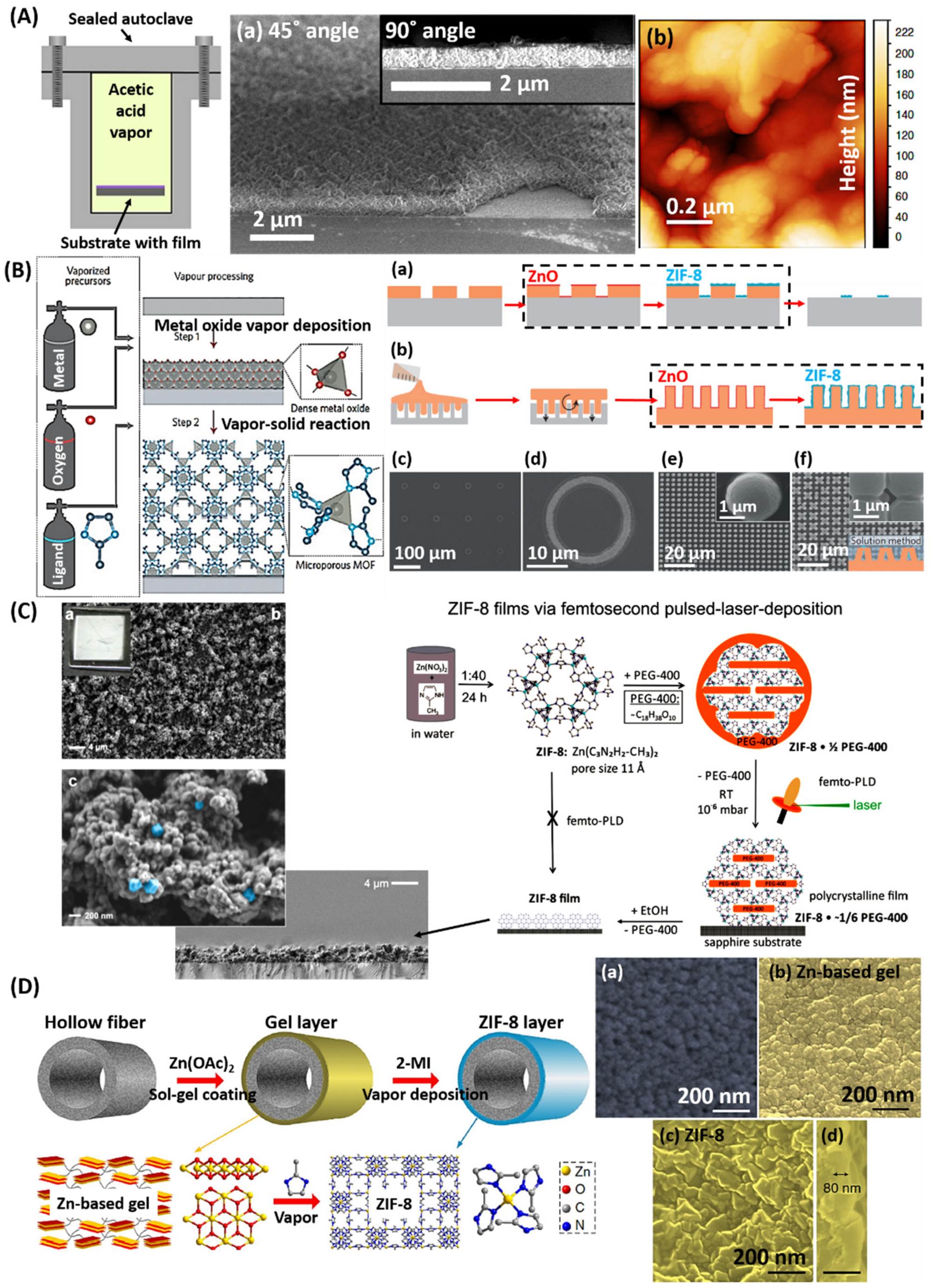
As mentioned previously, the ALD technique is widely used in seed-assisted secondary growth for MOF-TFs and in the preparation of metal precursor TFs and patterns. Other than these, ALD can also be directly employed to fabricate MOF-TFs via the vapor–solid reaction. In a general TF fabrication process via ALD, metal and organic precursors for the desired MOFs are sequentially blown onto the surface of a substrate with a pulse of gas to form the TF. Lausund and Nilsen [166] reported the deposition of UiO-66 (Zr6O4(OH)4(BDC)6) TFs via the ALD technique (Figure 12A). In this study, an amorphous organic–inorganic hybrid TF based on ZrCl4 and H2BDC formed on Si wafers. The vaporization temperatures for ZrCl4 and H2BDC were 165 and 220 °C, respectively. Then, the TF crystallized into a UiO-66 structure by heating to 160 °C for 24 h in a sealed autoclave with about 0.1 mL of acetic acid vapor. Uniform and continuous UiO-66 TFs were obtained locally on the wafer, acquiring a relatively low surface roughness. This ALD-based synthesis strategy provides an easy way to control the film thickness at an atomic level and is also available in the fabrication of multilayer structures. However, there are a few obstacles. First, the precursors, especially the organic precursors, must be volatile but not be subject to unwanted decomposition during the vaporization. Then, the capital cost of ALD equipment is high, and the process of ALD is slow, which prevents broad application of this technique.
The CVD technique is another type of vapor-based synthesis strategy in the fabrication of MOF-TFs with precisely controlled thicknesses. There are two steps in a general CVD process for fabricating MOF-TFs, including a metal oxide deposition step and a vapor–solid reaction step (Figure 12B). Stassen et al. [167] developed the concept of a CVD-based synthesis strategy for MOF-TFs. In this study, the ZnO layer was deposited first via ALD, and then the 2-mIm organic linker vapor was introduced to the reaction system via CVD, undergoing a metal oxide-to-MOF conversion process similar to the previously mentioned liquid/solid–solid synthesis. When fully converting 3 and 6 nm ZnO precursor layers, it resulted in ZIF-8 TFs with an average thickness of 52 and 104 nm, respectively. All the resulting ZIF-8 TFs achieved a uniform and controllable thickness. This CVD approach also realized lift-off patterning and fabrication of MOF-TFs on delicate features.
Considering the extensive studies in the fabrication of MOF-TFs via various chemical means, there is a rare investigation related to physical deposition. Concerning this, Fischer et al. [168] developed a femtosecond pulsed-laser deposition (femto-PLD) technique to achieve the fabrication of MOF-TFs, extending the fabrication of MOF-TFs to PVD (Figure 12C). In the study, ZIF-8 powder was stabilized in PEG-400 and then pressed into a pellet to prepare the target for femto-PLD. PEG@ZIF-8 TF was deposited on a sapphire substrate at room temperature by ablating the target in a high-vacuum system for 6 h. The femtosecond laser with a wavelength of 516 nm at 442 fs was operated with a laser power of 30 mW (energy per pulse of 0.03 mJ at 1 kHz), and the laser beam was focused on the target surface with a spot size of 0.05 mm. This method produced mesoporous ZIF-8 films consisting of nanosized ZIF-8 crystals as shown in the SEM images in Figure 12C. The limitation of this femto-PLD strategy is that it is applicable only to the fabrication of highly porous and thermally labile MOF-TFs with stabilizing additives.
5.3. Gel–Vapor Synthesis
Li et al. [169] introduced a gel–vapor deposition (GVD) strategy for the fabrication of MOF-TFs (Figure 12D). This method combines sol-gel coating with vapor deposition to receive the benefits from both techniques and realizes solvent-/modification-free and precursor-/time-saving synthesis of MOF-TFs with a controlled thickness. In this study, a Zn-based sol was prepared by mixing Zn(CH₃CO₂)₂·2H₂O and ethanolamine in ethanol and then coated on ammoniated polymer hollow fibers. The formation of Zn-based gel was initiated by heat treatment; the gel was then subjected to the conversion process of gel-to-MOF by introducing a vapor of organic linkers. An ultrathin ZIF TF thinner than 20 nm was obtained by adjusting the sol concentration and coating procedure. Unlike the liquid–solid reaction, the GVD process based on gas–solid reactions does not involve the diffusion of precursors in solutions and thereby offers better control over the reactant transport and fluid dynamics during crystallization. The GVD process requires no pretreatment of substrates and can be applied to many types of substrates. However, the MOF-TFs prepared via this strategy may face a problem of shrinkage and cracking during drying.
5.4. Post-Assembly Method
Most synthesis strategies to fabricate MOF-TFs use separate metal and organic linker precursors; the process often involves a chemical reaction step and a framework assembly step. There is a different strategy, using preformed MOF particles on substrates, to achieve MOF-TFs, which involves only the framework assembly step. Building on the extensive knowledge learned about the synthesis of MOF particles, MOF-TFs can be fabricated via a post-assembly process through a variety of strategies.
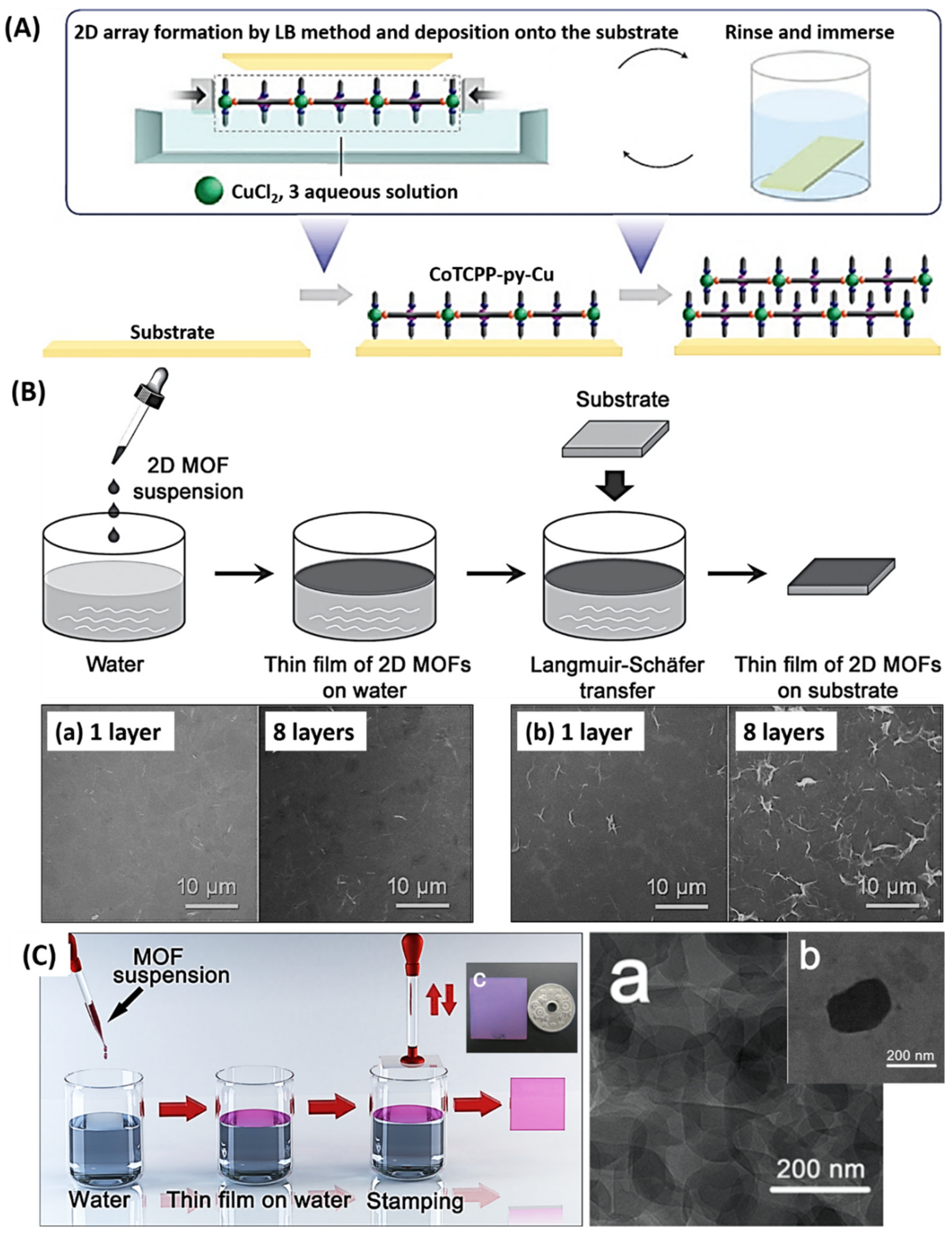
The Langmuir–Blodgett (LB) deposition method is a well-established technique for the fabrication of orderly monolayers on liquid–substrate surfaces, which is often applied using the LBL deposition strategy to assemble preformed MOF NCs for the formation of dense MOF-TFs. Makiura et al. [170] demonstrated the fabrication of MOF-TFs via the LB-LBL deposition strategy (Figure 13A). In this study, organic CoTCPP (tetrakis(4-carboxyphenyl)-porphyrin-cobaltII) and pyridine were spread onto an aqueous solution containing CuCl2 and formed a layer of CoTCPP-pyridine-Cu (NAFS-1) MOF nanosheets on the solution surface. The MOF monolayer was compressed by the container’s walls and received proper surface pressure. Then, the layered MOF nanosheets were transferred onto a smooth surface (Si wafer or quartz substrate) via the LB method. The process was repeated several times in an LBL manner to obtain an interdigitated NAFS-1 MOF-TFs. MOF-TFs prepared by the LB-LBL deposition strategy show the low surface roughness and high homogeneity, and the film thickness can be adjusted by the number of deposited layers and is accurate to the nanometer level [170,171,172,173,174,175,176,177]. Moreover, the choice of substrates for this type of MOF-TF deposition strategy is widely open. However, due to the weak interactions (p stacking or Van der Waals’ force) between the film and the substrate, MOF-TFs prepared by the LB method may easily fall off. Furthermore, the requirement of a generally expensive LB device for the deposition largely limits its application.
Another similar strategy, the Langmuir–Schäfer (LS) deposition, has also been applied to fabricate thin layers of MOFs based on preformed MOF NCs. Wang et al. [178] reported the fabrication of a series of M-TCPP(Fe) (M = Co, Cu, and Zn) MOF-TFs via the LS deposition strategy (Figure 13B). Unlike the LB deposition method, where the substrate is slowly immersed into and then withdrawn from the surface, yielding a mono-/multilayered TF, the substrate in the LS method is situated in a horizontal position and slowly put in contact with the liquid surface and subsequently lifted off the liquid surface. In this study, 2D M-TCPP(Fe) nanosheets were first prepared via a surfactant-assisted solvothermal synthesis, followed by the deposition onto substrates by the LS deposition process to obtain mono-/multilayers. Take the deposition of Co-TCPP(Fe) as an example. First, Co(NO3)2, pyrazine, and polyvinylpyrrolidone were dissolved in a mixture of DMF and ethanol (V:V = 3:1), and then mixed with TCPP(Fe) in another mixture of DMF and ethanol (V:V = 3:1). After the solution was sonicated for 10 min, the mixture was set to 80 °C for 24 h. The resulting dark brown products were washed twice with ethanol and collected by centrifuge. Finally, the obtained Co-TCPP(Fe) nanosheets were dispersed in ethanol to obtain a colloidal suspension with a concentration of 1.0 mg/mL. Then, the suspension was gently dropped onto the surface of water in a beaker. After Co-TCPP(Fe) nanosheets spontaneously spread to form a TF on water, the film was transferred onto a solid substrate via the LS method. Finally, the TF-coated solid substrate was immersed into fresh water to remove the loosely deposited nanosheets and then blow-dryed with N2. By this step, one deposition cycle was completed. Similar to the LB method, the LS method could follow an LBL deposition manner to control the thickness of the resulting MOF-TFs. The resulting Co-TCPP(Fe) MOF-TF with five deposition layers showed the best electrochemical catalytic activity toward the reduction of H2O2, with a limit of detection of 0.15 × 10⁻⁶ mol/L. The developed sensor was available for real-time detection of H2O2 secreted by live cells.
Xu et al. [179] reported a modular assembly strategy based on LS deposition to prepare MOF-TFs (Figure 13C), which realized a rapid fabrication of oriented MOF-TFs with larger domain sizes than the ones in the LB method [170]. Cu-TCPP nanosheets were first synthesized via a solvothermal reaction of Cu(NO3)2 and H2TCPP. The formed MOF nanosheets were first dispersed in ethanol to form a colloidal suspension and then added onto the surface of the water in a beaker dropwise to create a TF of Cu-TCPP MOF. The MOF-TF was then transferred to a quartz substrate via stamping. Repeating the stamping process in an LBL manner increases the film thickness. A highly oriented MOF-TF of 100 layers can be prepared within 10 min, enabling the preparation of oriented MOF-TFs in a shorter time than many previously reviewed fabrication techniques, although the orientation of the resulting TF depends only on the orientation of nanosheets obtained from bulk MOF synthesis. An obstacle in widening the application of the LS strategy is, similar to the LB strategy, the requirements of preformed MOF crystals with high aspect ratios can obtain a uniform air–liquid interface for MOF-TF deposition, which remains a significant challenge in the synthesis of MOFs.
6. Modification of MOF-TFs
For practical application aspects of view, such as gas sensing, a real gas environment is often a multi-component system. Consequently, selective adsorption of a specific molecule from a gas mixture is desired. Although MOF-TFs, by nature, provide excellent selective adsorption over many chemical species at the molecular level, their selectivity still cannot meet the requirements in practical applications [180]. Besides, many MOF-TFs have inadequate proton-conductivity capacities and are preferable for fabrication on conductive substrates for electronic gas sensing [181], but the inorganic substrates are relatively expensive. Although promising in lowering the cost, the fabrication of MOF-TFs on porous polymers is still limited by techniques because of the poor combination force between substrates and MOF-TFs [135]. Therefore, part of the research interest is shifting to the modification of MOF-TFs, such as modifying the macro-/micro-structures and tuning the pore functionality. The modification of MOF-TFs can be conducted on, but not limited to, ligands, metal sites, pores, and the overall hierarchical structure.
The modification of MOF-TFs can be classified into two categories, i.e., the in situ modification during synthesis, and the post-synthesis modification.
6.1. In Situ Modification
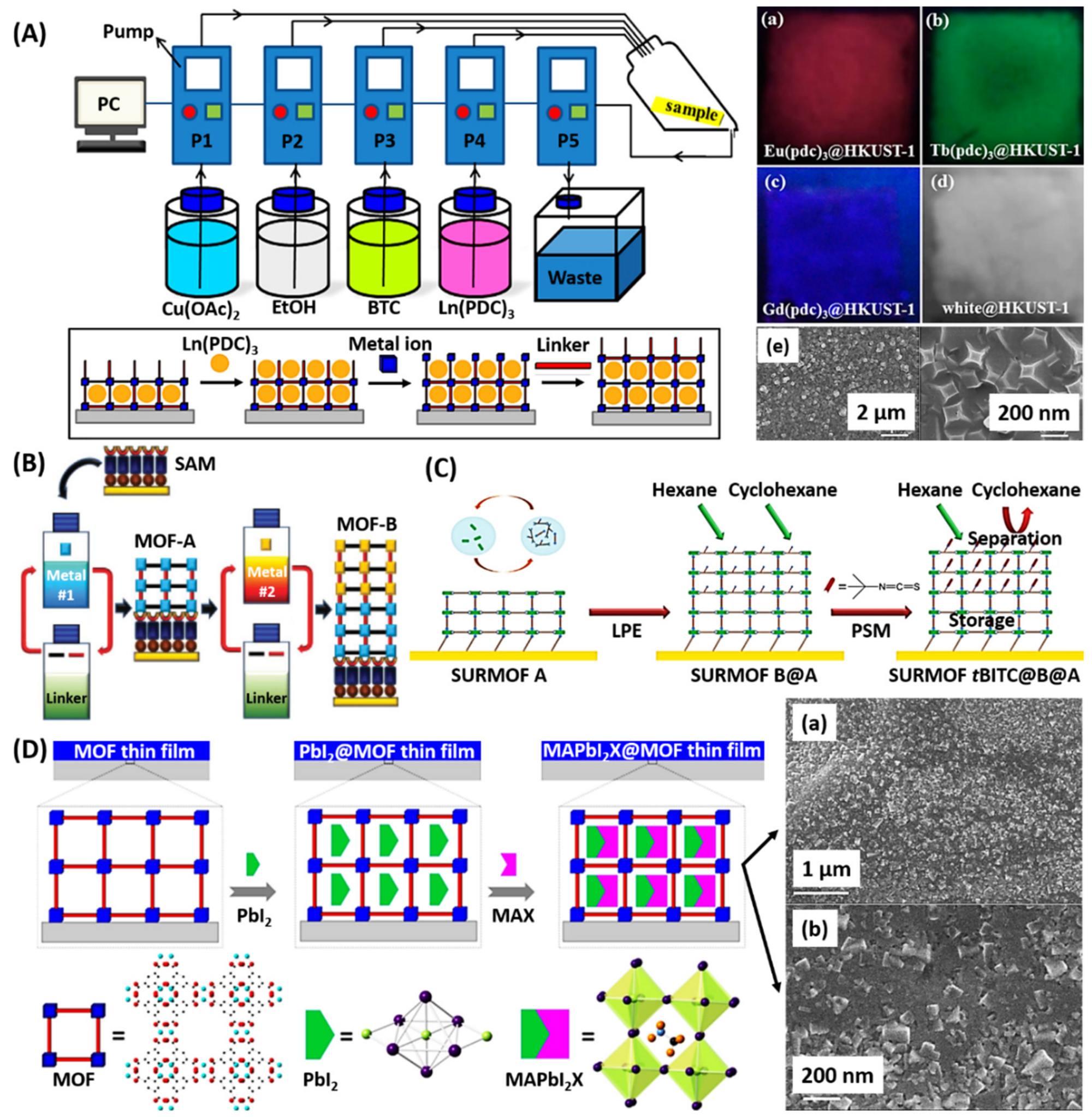
Mao et al. [182] developed a modification strategy to functionalize MOF-TFs during the fabrication process based on the functionalization of self-sacrificing metal hydroxide templates. In the study, copper hydroxide nanostrands (CHNs) were first mixed with different negatively charged functional species, including Au NPs, [AuCl4]− anions, ferritin, and glucose oxidase (GOx), polystyrene spheres, and single-walled carbon NTs (SWCNTs), and then filtered onto porous substrates. Followed by a 1-h reaction with H3BTC solution at room temperature, HKUST-1 composite TFs with encapsulated functional components were obtained. The resulting HKUST-1 TFs that encapsulated with different functional species exhibited interesting hybrid functions. The GOx/HKUST-1 composite TF showed interesting enzymatic activity toward glucose. The Au NP/HKUST-1 composite TF presented an excellent catalytic performance in the oxidation of CO, with a catalysis efficiency of 297.62 × 10⁻⁶ mol/gAus at 160 °C based on 50% conversion. The SWCNT/HKUST-1 composite TF possessed impressive conductivity and flexibility, showing a large BET surface area of 1192 m2/g and high thermal decomposition temperature of 333 °C. This synthesis strategy offers a route to encapsulate functional species into an MOF system, obtaining synergistic and size-selective functional materials. LBL deposition is capable of encapsulating guest molecules into the structure of MOF-TFs. Gu et al. [183] reported in situ LBL growth of lanthanide coordination compound-encapsulated MOF-TFs using a modified LPE pump method (Figure 14A). In this study, the Ln(PDC)3 (PDC = pyridine-2,6-dicarboxylate; Ln = Eu, Tb, and Gd) was encapsulated in the pores of MOFs during the fabrication process for HKUST-1 TF via the LBL deposition strategy. The resulting composite TFs showed RGB (red, green, and blue) primary colors because of the loading of Ln(PDC)3. Moreover, the proportion of different Ln(PDC)3 in the mixture can be adjusted to obtain a TF of white light emission. This synthesis strategy was useful in the development of oriented and homogeneous solid-state lighting composite TFs with a high encapsulation efficiency. Later, Fu et al. [184] employed this synthesis strategy and obtained a trans-azobenzene@HKUST-1 hybrid TF by immersing the substrate in Cu(CH3COO)2 solution, H3BTC solution, and trans-azobenzene solution, sequentially. The resulting hybrid MOF-TF possessed photo-switching and photoluminescent properties based on the trans-azobenzene, and a temperature-dependent photoluminescent emission, leading to a new path for the preparation of photochromic TFs and the development of multifunctional optical devices and sensors.
Another way of in situ modification for MOF-TFs is the stratified synthesis strategy, which enables MOF-on-MOF heterostructures with hierarchical porosity. Shekhah et al. [115] demonstrated the feasibility of the LBL deposition strategy in the stratified synthesis for MOF-on-MOF TFs (Figure 14B). First, SAMs were deposited on Au/Ti/Si wafers or Au substrate in an ethanolic solution of 4,(4-pyridyl)phenyl-methanethiol. Ethanolic solutions of zinc acetate or copper acetate and an equimolar H2NDC/DABCO (DABCO = 1,4-diazabicyclo(2.2.2)octane) mixture were used as precursors for each MOF. The MOF-TFs were fabricated via the traditional LBL deposition method, in which the substrates were first immersed in metal acetate solution for 30 min and then in the H2NDC/DABCO solution mixture for 60 min, with a washing step with pure ethanol of 5 min in between. The MOF-on-MOF fabrication was completed by 60 LBL cycles of first MOF-TF and then 60 LBL cycles of the second MOF-TF. In the end, highly oriented Zn-MOF-on-Cu-MOF hybridized TFs were obtained on SAM-based substrates, showing precisely controlled thicknesses, a result of the LBL deposition. Many different MOFs were studied using stratified synthesis, including MOF-on-MOF heterostructures [116] and MOF@MOF core-shell hybrid TFs [117].
6.2. Post-Synthesis Modification
Other than the in situ modification during fabrication, the functionality of MOF-TFs can be modified by a post-synthesis modification (PSM) process.
Shekhah et al. [185] used layer-pillar-based SURMOFs with BDC-NH2 linker as a robust platform to attach ferrocene via a PSM process. First, the SURMOF was synthesized on an SAM-modified Au(111) surface terminated with -OH groups from 11-mercaptoundecanol. The layer-pillar-type SURMOF consisted of Cu2(BDC-NH2)2 MOF nanosheets connected by DABCO pillars. 1-ferrocenylmethy-lisocyanate was used as the PSM reagent. To perform PSM, a pristine SURMOF was immersed in a solution of 1-ferrocenylmethy-lisocyanate dissolved in dichloroethane at 30 °C. After the PSM, the SURMOF could provide a maximum density of two ferrocene molecules per pore. The encapsulation of ferrocene inside the pores would alter the electrochemical properties of the SURMOFs. Based on the size-selective adsorption property of MOFs, many small molecules, such as redox-active compounds [186] and fluorescent dye molecules [187], can be encapsulated in MOF pores for integrated properties. Partial linker exchange can also be achieved via the PSM by tuning the reaction conditions [188].
Based on an MOF-on-MOF heterostructure via stratified synthesis, further modification of the pore functionality is available through a PSM process. Tu et al. [189] fabricated an SURMOF-on-SURMOF hybrid TF on the pyridyl-terminated Au-covered QCM substrate via LPE growth (Figure 14C). The fabrication of SURMOFs followed the LBL deposition manner, including 5-min immersion in copper acetate solution, 10 min in BDC/DABCO solution, and 5 min in ethanol for washing purposes between the two precursors. Before PSM, the SURMOFs were kept in dichloromethane overnight, followed by treatment under vacuum overnight at room temperature. Then, the activated samples were exposed to the vapor of tert-butyl isothiocyanate (tBITC) under static vacuum at room temperature for two days. Afterward, the modified SURMOFs were treated under a dynamic vacuum at room temperature for 1 day to remove physically adsorbed tBITC molecules. Through the PSM, the pore size of the top SURMOF, Cu2(BDC-NH2)2(DABCO) MOF was modified by targeting the amino groups with tert-butyl isothiocyanate (tBITC). This hybrid TF with a modified surface layer presented extraordinary separation and storage of hexane over cyclohexane according to the unique size selectivity from the small pore size of the outer SURMOF achieved via the PSM process and the high storage capacity from the inner SURMOF without modification. Chen et al. [190] conducted an oriented MOF-TF via the LPE approach as a host for perovskite QD fabrication (Figure 14D). By introducing PbI2 and CH3NH3X (MAX; X = Cl, Br, and I) precursors into an HKUST-1 TFs, perovskite MAPbI2X QDs were synthesized in the pores of the HKUST-1 TF with uniform diameters of 1.5–2 nm, which matched the pore size of HKUST-1. This perovskite QD@MOF-TFs was shown to be stable to moist air with 70% humidity for 4 days. This strategy provides confined synthesis of perovskite QDs with high stability and a uniform size distribution according to the oriented MOF-TF, broadening the application of perovskite QDs in luminescent sensors, photovoltaic solar cells, and other optoelectronic devices.
7. Patterning of MOF-TFs
There are several ways to prepare patterned MOF-TFs following previously discussed synthesis strategies. The patterning strategies can be grouped into three categories, i.e., bottom-up patterning of the substrate surface, top-down patterning of the substrate surface, and patterning of templates.
Patterned substrate surface via the bottom-up strategy can be realized by patterning functional groups on the substrate surface that either supports the growth of MOFs or prohibits it on desired areas. μCP is the most popular technique to pattern SAM layers for the fabrication of patterned MOF-TFs [59,107,125,191]. Precise SAM patterns (e.g., dots, squares, and lines), facilely prepared by the μCP technique, can result in accurately controlled MOF patterns. Besides SAMs, other alternatives can assist the patterned fabrication of MOF-TFs. Liang et al. [192] reported the fabrication of patterned MOF-TFs on substrates based on printed protein patterns (Figure 15A). Protein patterns of bovine serum albumin (BSA) were created on Si wafers and PET polymer films via stamping that transferred the aqueous BSA solution. Then, MOF precursor solutions were added onto the BSA patterns to form MOF crystals confined to the patterned areas. The patterning of MOFs can be achieved only on BSAs because BSAs can rapidly accumulate metal cations and organic ligands in solution, which accelerated the growth rate of MOFs on the pattered area. For the synthesis of ZIF-8 TFs and patterns, a fresh mixture of zinc acetate and 2-mIm was prepared in deionized water and transferred onto the BSA patterns. ZIF-8 patterns were obtained after 12 h. A similar process was performed for the fabrication of patterned Ln2(BDC)3 MOF-TFs and patterns. A fresh mixture of LnCl3 (Ln = Tb, Eu, and Ce) and Na2BDC was prepared in deionized water and transferred onto the BSA patterns. After 30 s of reaction, LMOF patterns were obtained. By this means, ZIF-8 and luminescent Ln2(BDC)3 MOF-TFs (including patterns) can be achieved on both rigid and flexible substrates.
Other fabrication techniques based on the bottom-up strategy are also available for MOF-TFs. As mentioned previously, ECD methods are quite accessible in the fabrication of patterned MOF-TFs. Li et al. [145] created desired patterns by writing PDMS on a conductive FTO substrate surface to fabricate patterned MOF-TFs via ECD. According to the insulating nature of PDMS, Ln(OH)3 was only electrochemically deposited on the surface area without PDMS, thereby resulting in the formation of patterned Ln-MOF TFs on the exposed FTO glass surface. These LMOF-TFs and patterns are of interest in the fields of MOF-based biosensors, bio-medical devices, color displays, anti-counterfeiting, and potentially aids in crime scene investigation.
Patterned substrate surfaces can also be made via the top-down strategy. Navarro et al. [193] reported the preparation of patterned MOF-TFs based on a patterned substrate via laser ablation (Figure 15B). In this study, brass sheets were used as substrates and patterned physically by using laser irradiation to create lines, dots, and holes on the substrate. A 20 W Nd:YAG laser technique was used for ablation, which created different roughness for different areas on the substrate. Porous substrates with 1.6% and 18% porosities and 20-32 mm effective micro-perforation diameters were obtained. After creating different surface roughness, the formation of ZIF-8 TFs followed traditional solvothermal synthesis in an autoclave at 100 °C for 4–8 h, depending on different samples. Varied surface roughness would lead to different nucleation and growth rates of ZIF-8 TFs, which resulted in the patterning of ZIF-8 TFs. Other than this, the formed ZnO from Zn oxidation during laser irradiation was likely another key factor to promoting the preferred formation of ZIF-8 TFs on the laser-irradiated areas. The obtained ZIF-8 pattern on porous brass sheets exhibited excellent separation performance for H2/CH4 and He/CH4 mixtures, showing separation factors of 14.4 and 8.7, respectively.
In addition, patterned MOF-TFs can be made by patterning self-sacrificing metal oxide or hydroxide templates. Reboul et al. [194] demonstrated the fabrication of patterned Al(OH)(NDC) MOF-TFs via self-sacrificing synthesis based on a patterned Al2O3 template (Figure 15C). The 2D/3D Al2O3 structures were prepared through a sol-gel process with polystyrene beads as the hard templates at 100 °C, which were removed through calcination at 580 °C for 7 h before the conversion of Al2O3 to Al(OH)(NDC) MOFs. The obtained Al2O3 templates were placed in a microwave container containing an aqueous H2NDC solution, followed by a microwave treatment at 180 °C for 10 min. The microwave treatment was performed at 180 °C for 1 min. The microwave treatment to make mesoporous and macroporous structures of Al(OH)(NDC) MOFs was performed at 180 °C for 1 min. The resulting Al(OH)(NDC) MOF architectures with hierarchical porosity presented enhanced selectivity and mass transfer for water/ethanol separation due to the hydrophobic micropores of Al(OH)(NDC) and the mesopores/macropores inherited from the parent aerogels. The room temperature separation selectivity for water/ethanol was 2.26 for microporous Al(OH)(NDC) MOF crystals, 2.56 for the mesoporous structure, and 1.84 for the macroporous structure. It was suggested that the smaller pore size of the mesoporous structure and the higher exposed surface area of Al(OH)(NDC) MOF within this architecture allowed higher ethanol retention and improved separation selectivity. Other than using hard templates, photolithography is another way to direct the preparation of metal oxide templates to fabricate patterned MOF-TFs [195]. Moreover, hard templates can be applied in the interfacial synthesis of MOFs to achieve patterned MOF-TFs [128].
8. Conclusions
In conclusion, this review summarizes the current progress on the manufacturing of MOF-TFs, from the general fabrication techniques to the modification and patterning techniques. All the reported techniques in the synthesis of MOF-TFs were discussed, including their advantages and disadvantages, which can guide advancement in the fabrication processes of MOF-TFs to realize more controllable, scalable, and greener processing.
MOF-TFs, fabricated using different strategies, perform differently due to the differences in the resulting grain size, surface roughness, film thickness, film stabilities, etc. Although extensive studies have been carried out, the fundamental understanding of the MOF-TF formation process, including precursor reaction kinetics, surface reaction kinetics, reactant transport, film nucleation, and growth, is still at an early stage; more research is needed before the application of MOF-TFs at the industry scale. Considerable progress needs to be made to realize the controlled and green synthesis of MOF-TFs, especially for scale-up production, despite the emergence of many fabrication strategies for functional MOF-TFs.
Currently, direct synthesis and secondary growth strategies based on traditional hydro/solvothermal batch synthesis are still two of the most extensively used methods for their easy conduction. However, they possess a time-dependent growth rate for MOF-TFs, lending difficulty in controlling the fabrication process, which may result in an uncontrollable film thickness, and surface morphology. Moreover, the batch reaction often requires a high cost from large reactant consumption and waste production. Furthermore, there is a potential safety issue when using a high-pressure reactor. LBL deposition, ECD, DC deposition, and SC deposition are prevalent in the manufacturing of MOF-TFs and patterns. The LBL deposition strategy can realize the fabrication of many types of MOF-TFs and enable precise control of the amount and location/distribution of functionalities for tailored properties. It offers excellent control over the film thickness, gives rise to highly oriented and uniform TFs, and enables the fabrication of more complex MOF heterostructures. However, it shows its limitation on the fabrication of some types of MOF-TFs on specific substrates, and a slow growth rate for MOF-TFs.
Moreover, to achieve uniform films, the volume of precursor solutions used for the substrates to be immersed in is much larger than that of the substrate, contributing to a significant amount of solution wastage. The ECD strategy allows the rapid fabrication of defect (cracks and pinholes)-free MOF-TFs with controllable thicknesses. Relatively uniform and compact deposits can be made in template-based structures; ECD also has the advantages of higher deposition rates and inexpensive equipment due to the non-requirements of either a high vacuum or a high reaction temperature. However, it is limited to electrochemical deposition of non-conductive MOF-TFs on conductive substrates. Moreover, metal ions with high inertness could separate on the cathode, and the organic linkers may be oxidized.
Both the DC deposition and the SC deposition are simple methods to fabricate MOF-TFs. They can achieve thin uniform TFs with a wide range of thicknesses (from nm to μm). Both methods utilize small equipment that is less expensive than the setup in many other methods (e.g., ECD, HoP, and ALD), and they do not require high energy processes. These two techniques are ideal for coating MOF-TFs on flat substrates, not curved or flexible ones. Besides different operation procedures, there are several distinct features of these two techniques. First, the DC technique is available in large-scale TF manufacturing while the SC technique can only be applied to small substrates. Then, the drying time needed in DC deposition is significantly long while that in SC deposition is short, which may alter the film formation process due to the different times. Both methods result in high solution wastage. Similar to the LBL deposition, the DC deposition also requires a solution reservoir to immerse the substrate. The volume of the solution is much higher than the size of the substrate, leading to a high quantity of solution wastage. During SC deposition, the majority of the solution is cast off, resulting in high levels of solution wastage.
There are other types of fabrication techniques that have been reviewed that show an ability for controllable fabrication of MOF-TFs and patterns. Despite their novelty, there are many obstacles to broadening their application. For example, the HoP technique can realize the fabrication of various MOF-TFs on flexible materials with controllable scale, which could be of interest in flexible electronics. However, it requires high thermal stability of MOFs and substrates.
Considering the requirements of scale-up production with effective cost, the commercialization of MOF-TFs appears quite challenging. Despite the development of novel techniques to achieve green synthesis in terms of reduced chemical consumption and low waste production, which also significantly influences the production cost, it is hard to fulfill other requirements. For example, the ALD technique offers an easy way to control the film thickness at an atomic level and is available in the fabrication of multilayer structures. However, it only works on certain types of MOFs that use volatile but thermally stable organic precursors. Moreover, ALD equipment is expensive, and the process is slow, which increases the operation cost. ECD and DC methods are promising in realizing large-scale controllable manufacturing of MOF-TFs and patterns. However, they could not satisfy the strict requirements for low cost and green synthesis. Although the equipment used in these techniques could be relatively low, the ECD technique requires high energy input while the DC technique contributes to high levels of waste production. Currently, there is no ideal technique that can satisfy all the requirements for commercialization.
The recent advancements in the continuous-flow microreactor and process automation lead to new opportunities in advancing the progress on commercializing MOF-TFs. The synthesis of MOFs using systems involving microfluidics has been widely investigated [64]. Due to its small size, a microreactor can offer several advantages, including fast mixing of the reactants, an efficient way for mass and heat transfer, and precise control of the reaction dynamics. [196] The use of less liquid volume allows for greener synthesis and lowers the production cost. Besides, current progress in using automatic methods for MOF synthesis demonstrates promising results in the manufacturing of freestanding fine powders (including nanocomposites) [64,197] and membranes [64] on porous supports. However, there is no implementation of microfluidic-assisted techniques for the fabrication of MOF-TFs and patterns on the substrate surface. Coupling microreactors with current state-of-the-art deposition techniques to fabricate MOF-TFs could realize more exceptional control over synthesis conditions. It has the potential to enable more scalable, controllable, and greener synthesis in terms of controlling the TF formation process, shortening the fabrication time, reducing reactant consumption and waste production, and allowing for mechanical automatization amenable for scale-up. A wide range of film thicknesses (from nm to μm) and areas (from nm to cm) could be obtained on heterogeneous hierarchical TFs and patterns via microfluidic-assisted techniques. Moreover, it is known that the formation of highly ordered MOF crystals occurs first via an assembly of primary building blocks to define the secondary building blocks (SBUs) and then to the MOF crystallites [198]. Therefore, SBUs are the ideal seeds for the growth of MOF crystals [199,200]. However, the SBU-assisted secondary growth strategy is currently limited to the fabrication of bulk MOFs. Yet, it is promising in supporting TF fabrication without introducing foreign elements in the desired MOF structures.
Although extensive investigations and significant progress have been made for MOFs, due to their enormous chemistry possibility, there remains considerable room for future exploration and advancement. This review summarized and analyzed existing manufacturing techniques for MOF-TFs, including patterning, offering direction to researchers for the next generation development of MOF-TF processing, and building a foundation to realize the commercialization of MOFs, of which cost control and scale-up production are the two cores.
Author Contributions
Conceptualization, C.-H.C. and Y.Z.; writing—original draft preparation, Y.Z.; writing—review and editing, C.-H.C. All authors have read and agreed to the published version of the manuscript.
Funding
This project was also partially funded by the National Science Foundation (NSF) under grant No. ECCS-1707506 and Scalable Nanomanufacturing program under Grant No. CBET-1449383.
Acknowledgments
We like to thank Alvin Chang for his assistance in improving the writing.
Conflicts of Interest
The authors declare no conflict of interest.
References
- Yaghi, O.M.; Li, G.; Li, H. Selective binding and removal of guests in a microporous metal-organic framework. Nature 1995, 378, 703–706. [Google Scholar] [CrossRef]
- Dietzel, P.D.; Besikiotis, V.; Blom, R. Application of metal-organic frameworks with coordinatively unsaturated metal sites in storage and separation of methane and carbon dioxide. J. Mater. Chem. 2009, 19, 7362–7370. [Google Scholar] [CrossRef]
- Murray, L.J.; Dincă, M.; Long, J.R. Hydrogen storage in metal-organic frameworks. Chem. Soc. Rev. 2009, 38, 1294–1314. [Google Scholar] [CrossRef] [PubMed]
- Li, B.; Wen, H.-M.; Zhou, W.; Chen, B. Porous metal-organic frameworks for gas storage and separation: What, how, and why? J. Phys. Chem. Lett. 2014, 5, 3468–3479. [Google Scholar] [CrossRef] [PubMed]
- Li, H.; Wang, K.; Sun, Y.; Lollar, C.T.; Li, J.; Zhou, H.-C. Recent advances in gas storage and separation using metal-organic frameworks. Mater. Today 2018, 21, 108–121. [Google Scholar] [CrossRef]
- Vlasova, E.; Yakimov, S.; Naidenko, E.; Kudrik, E.; Makarov, S. Application of metal-organic frameworks for purification of vegetable oils. Food Chem. 2016, 190, 103–109. [Google Scholar] [CrossRef] [PubMed]
- Mukherjee, S.; Desai, A.V.; Ghosh, S.K. Potential of metal-organic frameworks for adsorptive separation of industrially and environmentally relevant liquid mixtures. Coord. Chem. Rev. 2018, 367, 82–126. [Google Scholar] [CrossRef]
- Dhaka, S.; Kumar, R.; Deep, A.; Kurade, M.B.; Ji, S.-W.; Jeon, B.-H. Metal-organic frameworks (MOFs) for the removal of emerging contaminants from aquatic environments. Coord. Chem. Rev. 2019, 380, 330–352. [Google Scholar] [CrossRef]
- Wang, H.; Zhao, S.; Liu, Y.; Yao, R.; Wang, X.; Cao, Y.; Ma, D.; Zou, M.; Cao, A.; Feng, X. Membrane adsorbers with ultrahigh metal-organic framework loading for high flux separations. Nat. Commun. 2019, 10, 1–9. [Google Scholar] [CrossRef] [Green Version]
- Dhakshinamoorthy, A.; Li, Z.; Garcia, H. Catalysis and photocatalysis by metal organic frameworks. Chem. Soc. Rev. 2018, 47, 8134–8172. [Google Scholar] [CrossRef]
- Kousik, S.; Velmathi, S. Engineering metal-organic framework catalysts for C−C and C−X coupling reactions: Advances in reticular approaches from 2014–2018. Chem. Eur. J. 2019, 25, 16451–16505. [Google Scholar] [CrossRef] [PubMed]
- Pascanu, V.; González Miera, G.; Inge, A.K.; Martín-Matute, B.n. Metal-organic frameworks as catalysts for organic synthesis: A critical perspective. J. Am. Chem. Soc. 2019, 141, 7223–7234. [Google Scholar] [CrossRef] [PubMed] [Green Version]
- Yang, D.; Gates, B.C. Catalysis by metal organic frameworks: Perspective and suggestions for future research. ACS Catal. 2019, 9, 1779–1798. [Google Scholar] [CrossRef]
- Kreno, L.E.; Leong, K.; Farha, O.K.; Allendorf, M.; Van Duyne, R.P.; Hupp, J.T. Metal-organic framework materials as chemical sensors. Chem. Rev. 2012, 112, 1105–1125. [Google Scholar] [CrossRef] [PubMed]
- Kumar, P.; Deep, A.; Kim, K.-H. Metal organic frameworks for sensing applications. Trends Anal. Chem. 2015, 73, 39–53. [Google Scholar] [CrossRef]
- Chong, X.; Kim, K.-j.; Zhang, Y.; Li, E.; Ohodnicki, P.R.; Chang, C.-H.; Wang, A.X. Plasmonic nanopatch array with integrated metal-organic framework for enhanced infrared absorption gas sensing. Nanotechnology 2017, 28, 26LT01. [Google Scholar] [CrossRef]
- Fang, X.; Zong, B.; Mao, S. Metal-organic framework-based sensors for environmental contaminant sensing. Nano-Micro Lett. 2018, 10, 64. [Google Scholar]
- Chocarro-Ruiz, B.; Pérez-Carvajal, J.; Avci, C.; Calvo-Lozano, O.; Alonso, M.I.; Maspoch, D.; Lechuga, L.M. A CO2 optical sensor based on self-assembled metal-organic framework nanoparticles. J. Mater. Chem. A 2018, 6, 13171–13177. [Google Scholar] [CrossRef] [Green Version]
- Li, S.-L.; Xu, Q. Metal-organic frameworks as platforms for clean energy. Energy Environ. Sci. 2013, 6, 1656–1683. [Google Scholar] [CrossRef]
- Bon, V. Metal-organic frameworks for energy-related applications. Curr. Opin. Green Sustain. Chem. 2017, 4, 44–49. [Google Scholar] [CrossRef]
- Wu, H.B.; Lou, X.W.D. Metal-organic frameworks and their derived materials for electrochemical energy storage and conversion: Promises and challenges. Sci. Adv. 2017, 3, 9252. [Google Scholar]
- Qiu, T.; Liang, Z.; Guo, W.; Tabassum, H.; Gao, S.; Zou, R. Metal-organic framework-based materials for energy conversion and storage. ACS Energy Lett. 2020. [Google Scholar] [CrossRef] [Green Version]
- Ló, Y.; Zhan, W.; He, Y.; Wang, Y.; Kong, X.; Kuang, Q.; Xie, Z.; Zheng, L. MOF-templated synthesis of porous Co3O4 concave nanocubes with high specific surface area and their gas sensing properties. ACS Appl. Mater. Interfaces 2014, 6, 4186–4195. [Google Scholar] [CrossRef] [PubMed]
- Robson, R.; Abrahams, B.F.; Batten, S.R.; Gable, R.W.; Hoskins, B.F.; Liu, J. Crystal Engineering of Novel Materials Composed of Infinite Two-and Three-Dimensional Frameworks; ACS Symp. Ser. Am. Chem. Soc. 1992, 499, 256–273. [Google Scholar] [CrossRef]
- Fujita, M.; Kwon, Y.J.; Washizu, S.; Ogura, K. Preparation, clathration ability, and catalysis of a two-dimensional square network material composed of cadmium (II) and 4,4’-bipyridine. J. Am. Chem. Soc. 1994, 116, 1151–1152. [Google Scholar]
- Chui, S.S.-Y.; Lo, S.M.-F.; Charmant, J.P.; Orpen, A.G.; Williams, I.D. A chemically functionalizable nanoporous material [Cu3(TMA)2(H2O)3]n. Science 1999, 283, 1148–1150. [Google Scholar] [PubMed]
- Kim, K.-J.; Li, Y.J.; Kreider, P.B.; Chang, C.-H.; Wannenmacher, N.; Thallapally, P.K.; Ahn, H.-G. High-rate synthesis of Cu-BTC metal-organic frameworks. Chem. Commun. 2013, 49, 11518–11520. [Google Scholar]
- Zhuang, J.; Kuo, C.-H.; Chou, L.-Y.; Liu, D.-Y.; Weerapana, E.; Tsung, C.-K. Optimized metal-organic-framework nanospheres for drug delivery: Evaluation of small-molecule encapsulation. ACS Nano 2014, 8, 2812–2819. [Google Scholar] [CrossRef]
- Li, Y.-z.; Fu, Z.-h.; Xu, G. Metal-organic framework nanosheets: Preparation and applications. Coord. Chem. Rev. 2019, 388, 79–106. [Google Scholar] [CrossRef]
- Park, K.H.; Kim, M.H.; Im, S.H.; Park, O.O. Electrically bistable Ag nanocrystal-embedded metal-organic framework microneedles. RSC Adv. 2016, 6, 64885–64889. [Google Scholar]
- Hou, J.; Sapnik, A.F.; Bennett, T.D. Metal-organic framework gels and monoliths. Chem. Sci. 2020. [Google Scholar] [CrossRef] [PubMed] [Green Version]
- Zacher, D.; Shekhah, O.; Wöll, C.; Fischer, R.A. Thin films of metal-organic frameworks. Chem. Soc. Rev. 2009, 38, 1418–1429. [Google Scholar] [CrossRef] [PubMed]
- Li, W. Metal-organic framework membranes: Production, modification, and applications. Prog. Mater. Sci. 2019, 100, 21–63. [Google Scholar] [CrossRef]
- Li, S.; Limbach, R.; Longley, L.; Shirzadi, A.A.; Walmsley, J.C.; Johnstone, D.N.; Midgley, P.A.; Wondraczek, L.; Bennett, T.D. Mechanical properties and processing techniques of bulk metal-organic framework glasses. J. Am. Chem. Soc. 2018, 141, 1027–1034. [Google Scholar] [CrossRef] [Green Version]
- Longley, L.; Collins, S.M.; Li, S.; Smales, G.J.; Erucar, I.; Qiao, A.; Hou, J.; Doherty, C.M.; Thornton, A.W.; Hill, A.J. Flux melting of metal-organic frameworks. Chem. Sci. 2019, 10, 3592–3601. [Google Scholar] [CrossRef] [Green Version]
- Qiao, A.; Tao, H.; Carson, M.P.; Aldrich, S.W.; Thirion, L.M.; Bennett, T.D.; Mauro, J.C.; Yue, Y. Optical properties of a melt-quenched metal-organic framework glass. Opt. Lett. 2019, 44, 1623–1625. [Google Scholar] [CrossRef]
- Liao, Z.; Xia, T.; Yu, E.; Cui, Y. Luminescent metal-organic framework thin films: from preparation to biomedical sensing applications. Crystals 2018, 8, 338. [Google Scholar] [CrossRef] [Green Version]
- Cui, Y.; Zhang, J.; He, H.; Qian, G. Photonic functional metal-organic frameworks. Chem. Soc. Rev. 2018, 47, 5740–5785. [Google Scholar] [CrossRef]
- Song, X.; Wang, X.; Li, Y.; Zheng, C.; Zhang, B.; Di, C.a.; Li, F.; Jin, C.; Mi, W.; Chen, L. 2D semiconducting metal-organic framework thin films for organic spin valves. Angew. Chem. Int. Ed. 2019. [Google Scholar] [CrossRef]
- De Luna, P.; Liang, W.; Mallick, A.; Shekhah, O.; García de Arquer, F.P.; Proppe, A.H.; Todorović, P.; Kelley, S.O.; Sargent, E.H.; Eddaoudi, M. Metal-organic framework thin films on high-curvature nanostructures toward tandem electrocatalysis. ACS Appl. Mater. Interfaces 2018, 10, 31225–31232. [Google Scholar] [CrossRef]
- Kim, K.-J.; Chong, X.; Kreider, P.B.; Ma, G.; Ohodnicki, P.R.; Baltrus, J.P.; Wang, A.X.; Chang, C.-H. Plasmonics-enhanced metal-organic framework nanoporous films for highly sensitive near-infrared absorption. J. Mater. Chem. C 2015, 3, 2763–2767. [Google Scholar] [CrossRef]
- Chong, X.; Kim, K.-J.; Li, E.; Zhang, Y.; Ohodnicki, P.R.; Chang, C.-H.; Wang, A.X. Near-infrared absorption gas sensing with metal-organic framework on optical fibers. Sens. Actuators B Chem. 2016, 232, 43–51. [Google Scholar] [CrossRef]
- Chong, X.Y.; Zhang, Y.J.; Li, E.W.; Kim, K.J.; Ohodnicki, P.R.; Chang, C.H.; Wang, A.X. Surface-enhanced infrared absorption: Pushing the frontier for on-chip gas sensing. ACS Sens. 2018, 3, 230–238. [Google Scholar] [CrossRef] [PubMed]
- Bai, W.; Li, S.; Ma, J.; Cao, W.; Zheng, J. Ultrathin 2D metal-organic framework (nanosheets and nanofilms)-based x D-2D hybrid nanostructures as biomimetic enzymes and supercapacitors. J. Mater. Chem. A 2019, 7, 9086–9098. [Google Scholar] [CrossRef]
- Ahmad, S.; Liu, J.; Ji, W.; Sun, L. Metal-organic framework thin film-based dye sensitized solar cells with enhanced photocurrent. Materials 2018, 11, 1868. [Google Scholar] [CrossRef] [Green Version]
- Luo, J.; Li, Y.; Zhang, H.; Wang, A.; Lo, W.S.; Dong, Q.; Wong, N.; Povinelli, C.; Shao, Y.; Chereddy, S. A metal-organic framework thin film for selective Mg2+ transport. Angew. Chem. Int. Ed. 2019, 58, 15313–15317. [Google Scholar] [CrossRef]
- Koros, W.; Ma, Y.; Shimidzu, T. Terminology for membranes and membrane processes (IUPAC Recommendations 1996). Pure Appl. Chem. 1996, 68, 1479–1489. [Google Scholar] [CrossRef]
- Ter Minassian-Saraga, L. Thin films including layers: Terminology in relation to their preparation and characterization (IUPAC Recommendations 1994). Pure Appl. Chem. 1994, 66, 1667–1738. [Google Scholar] [CrossRef]
- Liu, T.-Y.; Yuan, H.-G.; Liu, Y.-Y.; Ren, D.; Su, Y.-C.; Wang, X. Metal-organic framework nanocomposite thin films with interfacial bindings and self-standing robustness for high water flux and enhanced ion selectivity. ACS Nano 2018, 12, 9253–9265. [Google Scholar] [CrossRef]
- Venkatasubramanian, A.; Navaei, M.; Bagnall, K.R.; McCarley, K.C.; Nair, S.; Hesketh, P.J. Gas Adsorption characteristics of metal-organic frameworks via quartz crystal microbalance techniques. J. Phys. Chem. C 2012, 116, 15313–15321. [Google Scholar] [CrossRef]
- Wannapaiboon, S.; Tu, M.; Sumida, K.; Khaletskaya, K.; Furukawa, S.; Kitagawa, S.; Fischer, R.A. Hierarchical structuring of metal-organic framework thin-films on quartz crystal microbalance (QCM) substrates for selective adsorption applications. J. Mater. Chem. A 2015, 3, 23385–23394. [Google Scholar] [CrossRef]
- Guo, W.; Zha, M.; Wang, Z.; Redel, E.; Xu, Z.; Wöll, C. Improving the loading capacity of metal-organic framework thin films using optimized linkers. ACS Appl. Mater. Interfaces 2016, 8, 24699–24702. [Google Scholar] [CrossRef] [PubMed]
- Shekhah, O. Layer-by-layer method for the synthesis and growth of surface mounted metal-organic frameworks (SURMOFs). Materials 2010, 3, 1302–1315. [Google Scholar] [CrossRef] [Green Version]
- Mártire, A.P.; Segovia, G.M.; Azzaroni, O.; Rafti, M.; Marmisollé, W. Layer-by-layer integration of conducting polymers and metal organic frameworks onto electrode surfaces: Enhancement of the oxygen reduction reaction through electrocatalytic nanoarchitectonics. Mol. Syst. Des. Eng. 2019, 4, 893–900. [Google Scholar] [CrossRef]
- Bhardwaj, S.K.; Bhardwaj, N.; Kaur, R.; Mehta, J.; Sharma, A.L.; Kim, K.-H.; Deep, A. An overview of different strategies to introduce conductivity in metal-organic frameworks and miscellaneous applications thereof. J. Mater. Chem. A 2018, 6, 14992–15009. [Google Scholar] [CrossRef]
- Yoo, Y.; Jeong, H.-K. Rapid fabrication of metal organic framework thin films using microwave-induced thermal deposition. Chem. Commun. 2008, 21, 2441–2443. [Google Scholar] [CrossRef]
- Kim, K.-J.; Zhang, Y.; Kreider, P.B.; Chong, X.; Wang, A.X.; Ohodnicki, P.R., Jr.; Baltrus, J.P.; Chang, C.-H. Nucleation and growth of oriented metal-organic framework thin films on thermal SiO2 surface. Thin Solid Films 2018, 659, 24–35. [Google Scholar] [CrossRef]
- Dimitrakakis, C.; Easton, C.D.; Muir, B.W.; Ladewig, B.P.; Hill, M.R. Spatial control of zeolitic imidazolate framework growth on flexible substrates. Cryst. Growth Des. 2013, 13, 4411–4417. [Google Scholar] [CrossRef]
- Hermes, S.; Schröder, F.; Chelmowski, R.; Wöll, C.; Fischer, R.A. Selective nucleation and growth of metal-organic open framework thin films on patterned COOH/CF3-terminated self-assembled monolayers on Au (111). J. Am. Chem. Soc. 2005, 127, 13744–13745. [Google Scholar] [CrossRef]
- Scherb, C.; Williams, J.J.; Hinterholzinger, F.; Bauer, S.; Stock, N.; Bein, T. Implementing chemical functionality into oriented films of metal-organic frameworks on self-assembled monolayers. J. Mater. Chem. 2011, 21, 14849–14856. [Google Scholar] [CrossRef] [Green Version]
- Julien, P.A.; Mottillo, C.; Friščić, T. Metal-organic frameworks meet scalable and sustainable synthesis. Green Chem. 2017, 19, 2729–2747. [Google Scholar] [CrossRef]
- Ji, Y.; Qian, W.; Yu, Y.; An, Q.; Liu, L.; Zhou, Y.; Gao, C. Recent developments in nanofiltration membranes based on nanomaterials. Chin. J. Chem. Eng. 2017, 25, 1639–1652. [Google Scholar] [CrossRef]
- Liu, Y.; Ban, Y.; Yang, W. Microstructural engineering and architectural design of metal-organic framework membranes. Adv. Mater. 2017, 29, 1606949. [Google Scholar] [CrossRef] [PubMed]
- Echaide-Górriz, C.; Clément, C.; Cacho-Bailo, F.; Téllez, C.; Coronas, J. New strategies based on microfluidics for the synthesis of metal-organic frameworks and their membranes. J. Mater. Chem. A 2018, 6, 5485–5506. [Google Scholar] [CrossRef] [Green Version]
- Zhu, J.; Hou, J.; Uliana, A.; Zhang, Y.; Tian, M.; Van der Bruggen, B. The rapid emergence of two-dimensional nanomaterials for high-performance separation membranes. J. Mater. Chem. A 2018, 6, 3773–3792. [Google Scholar] [CrossRef]
- Shekhah, O.; Chernikova, V.; Belmabkhout, Y.; Eddaoudi, M. Metal-organic framework membranes: From fabrication to gas separation. Crystals 2018, 8, 412. [Google Scholar] [CrossRef] [Green Version]
- Lin, R.; Hernandez, B.V.; Ge, L.; Zhu, Z. Metal organic framework based mixed matrix membranes: An overview on filler/polymer interfaces. J. Mater. Chem. A 2018, 6, 293–312. [Google Scholar] [CrossRef]
- Jeazet, H.B.T.; Staudt, C.; Janiak, C. Metal-organic frameworks in mixed-matrix membranes for gas separation. Dalton Trans. 2012, 41, 14003–14027. [Google Scholar] [CrossRef]
- Pettinari, C.; Marchetti, F.; Mosca, N.; Tosi, G.; Drozdov, A. Application of metal-organic frameworks. Polym. Int. 2017, 66, 731–744. [Google Scholar] [CrossRef]
- Mahata, P.; Mondal, S.K.; Singha, D.K.; Majee, P. Luminescent rare-earth-based MOFs as optical sensors. Dalton Trans. 2017, 46, 301–328. [Google Scholar] [CrossRef]
- Lustig, W.P.; Mukherjee, S.; Rudd, N.D.; Desai, A.V.; Li, J.; Ghosh, S.K. Metal-organic frameworks: Functional luminescent and photonic materials for sensing applications. Chem. Soc. Rev. 2017, 46, 3242–3285. [Google Scholar] [CrossRef] [PubMed]
- Stassen, I.; Burtch, N.; Talin, A.; Falcaro, P.; Allendorf, M.; Ameloot, R. An updated roadmap for the integration of metal-organic frameworks with electronic devices and chemical sensors. Chem. Soc. Rev. 2017, 46, 3185–3241. [Google Scholar] [CrossRef] [PubMed]
- Xu, K.; Fu, C.; Gao, Z.; Wei, F.; Ying, Y.; Xu, C.; Fu, G. Nanomaterial-based gas sensors: A review. Instrum. Sci. Technol. 2018, 46, 115–145. [Google Scholar] [CrossRef]
- Li, Y.; Xiao, A.-S.; Zou, B.; Zhang, H.-X.; Yan, K.-L.; Lin, Y. Advances of metal-organic frameworks for gas sensing. Polyhedron 2018, 154, 83–97. [Google Scholar] [CrossRef]
- Alrammouz, R.; Podlecki, J.; Abboud, P.; Sorli, B.; Habchi, R. A review on flexible gas sensors: From materials to devices. Sens. Actuators A Phys. 2018, 284, 209–231. [Google Scholar] [CrossRef]
- Kuyuldar, S.; Genna, D.T.; Burda, C. On the potential for nanoscale metal-organic frameworks for energy applications. J. Mater. Chem. A 2019, 7, 21545–21576. [Google Scholar] [CrossRef]
- Sosa, J.D.; Bennett, T.F.; Nelms, K.J.; Liu, B.M.; Tovar, R.C.; Liu, Y. Metal-organic framework hybrid materials and their applications. Crystals 2018, 8, 325. [Google Scholar] [CrossRef] [Green Version]
- Wang, S.; McGuirk, C.M.; d’Aquino, A.; Mason, J.A.; Mirkin, C.A. Metal-organic framework nanoparticles. Adv. Mater. 2018, 30, 1800202. [Google Scholar] [CrossRef]
- Zhu, Q.-L.; Xu, Q. Metal-organic framework composites. Chem. Soc. Rev. 2014, 43, 5468–5512. [Google Scholar] [CrossRef]
- Ameloot, R.; Vermoortele, F.; Vanhove, W.; Roeffaers, M.B.; Sels, B.F.; De Vos, D.E. Interfacial synthesis of hollow metal-organic framework capsules demonstrating selective permeability. Nat. Chem. 2011, 3, 382–387. [Google Scholar] [CrossRef]
- Li, J.; Wu, Q.; Wu, J. Synthesis of nanoparticles via solvothermal and hydrothermal methods. Handb. Nanopart. 2015. [Google Scholar] [CrossRef]
- Cui, X.-Y.; Gu, Z.-Y.; Jiang, D.-Q.; Li, Y.; Wang, H.-F.; Yan, X.-P. In situ hydrothermal growth of metal-organic framework 199 films on stainless steel fibers for solid-phase microextraction of gaseous benzene homologues. Anal. Chem. 2009, 81, 9771–9777. [Google Scholar] [CrossRef] [PubMed]
- Sheberla, D.; Sun, L.; Blood-Forsythe, M.A.; Er, S.l.; Wade, C.R.; Brozek, C.K.; Aspuru-Guzik, A.n.; Dincă, M. High electrical conductivity in Ni3(2,3,6,7,10,11-hexaiminotriphenylene)2, a semiconducting metal-organic graphene analogue. J. Am. Chem. Soc. 2014, 136, 8859–8862. [Google Scholar] [CrossRef] [PubMed]
- Campbell, J.; Tokay, B. Controlling the size and shape of Mg-MOF-74 crystals to optimise film synthesis on alumina substrates. Microporous Mesoporous Mat. 2017, 251, 190–199. [Google Scholar] [CrossRef]
- Liu, Y.; Ng, Z.; Khan, E.A.; Jeong, H.-K.; Ching, C.-b.; Lai, Z. Synthesis of continuous MOF-5 membranes on porous α-alumina substrates. Microporous Mesoporous Mat. 2009, 118, 296–301. [Google Scholar] [CrossRef]
- Yoon, S.M.; Park, J.H.; Grzybowski, B.A. Large-area, freestanding mof films of planar, curvilinear, or micropatterned topographies. Angew. Chem. Int. Ed. 2017, 56, 127–132. [Google Scholar] [CrossRef]
- Bux, H.; Chmelik, C.; van Baten, J.M.; Krishna, R.; Caro, J. Novel MOF-membrane for molecular sieving predicted by IR-diffusion studies and molecular modeling. Adv. Mater. 2010, 22, 4741–4743. [Google Scholar] [CrossRef]
- Liu, C.; Wu, Y.-n.; Morlay, C.; Gu, Y.; Gebremariam, B.; Yuan, X.; Li, F. General deposition of metal-organic frameworks on highly adaptive organic-inorganic hybrid electrospun fibrous substrates. ACS Appl. Mater. Interfaces 2016, 8, 2552–2561. [Google Scholar] [CrossRef]
- Van Vleet, M.J.; Weng, T.; Li, X.; Schmidt, J. In Situ, time-resolved, and mechanistic studies of metal-organic framework nucleation and growth. Chem. Rev. 2018, 118, 3681–3721. [Google Scholar] [CrossRef]
- Liu, J.; Wöll, C. Surface-supported metal-organic framework thin films: Fabrication methods, applications, and challenges. Chem. Soc. Rev. 2017, 46, 5730–5770. [Google Scholar] [CrossRef]
- Brower, L.J.; Gentry, L.K.; Napier, A.L.; Anderson, M.E. Tailoring the nanoscale morphology of HKUST-1 thin films via codeposition and seeded growth. Beilstein J. Nanotechnol. 2017, 8, 2307–2314. [Google Scholar] [CrossRef] [PubMed] [Green Version]
- Bradshaw, D.; Garai, A.; Huo, J. Metal-organic framework growth at functional interfaces: Thin films and composites for diverse applications. Chem. Soc. Rev. 2012, 41, 2344–2381. [Google Scholar] [CrossRef] [PubMed] [Green Version]
- Ulman, A. Formation and structure of self-assembled monolayers. Chem. Rev. 1996, 96, 1533–1554. [Google Scholar] [CrossRef]
- Biemmi, E.; Scherb, C.; Bein, T. Oriented growth of the metal organic framework Cu3(BTC)2(H2O)3·xH2O tunable with functionalized self-assembled monolayers. J. Am. Chem. Soc. 2007, 129, 8054–8055. [Google Scholar] [CrossRef]
- Liu, J.; Shekhah, O.; Stammer, X.; Arslan, H.K.; Liu, B.; Schüpbach, B.; Terfort, A.; Wöll, C. Deposition of metal-organic frameworks by liquid-phase epitaxy: The influence of substrate functional group density on film orientation. Materials 2012, 5, 1581–1592. [Google Scholar] [CrossRef] [Green Version]
- Zacher, D.; Baunemann, A.; Hermes, S.; Fischer, R.A. Deposition of microcrystalline [Cu3(btc)2] and [Zn2(bdc)2(dabco)] at alumina and silica surfaces modified with patterned self assembled organic monolayers: Evidence of surface selective and oriented growth. J. Mater. Chem. 2007, 17, 2785–2792. [Google Scholar] [CrossRef]
- Hinterholzinger, F.; Scherb, C.; Ahnfeldt, T.; Stock, N.; Bein, T. Oriented growth of the functionalized metal-organic framework CAU-1 ON–OH-and–COOH-terminated self-assembled monolayers. Phys. Chem. Chem. Phys. 2010, 12, 4515–4520. [Google Scholar] [CrossRef]
- McCarthy, M.C.; Varela-Guerrero, V.; Barnett, G.V.; Jeong, H.-K. Synthesis of zeolitic imidazolate framework films and membranes with controlled microstructures. Langmuir 2010, 26, 14636–14641. [Google Scholar] [CrossRef]
- Zhou, M.; Li, J.; Zhang, M.; Wang, H.; Lan, Y.; Wu, Y.-n.; Li, F.; Li, G. A polydopamine layer as the nucleation center of MOF deposition on “inert” polymer surfaces to fabricate hierarchically structured porous films. Chem. Commun. 2015, 51, 2706–2709. [Google Scholar] [CrossRef]
- Bux, H.; Feldhoff, A.; Cravillon, J.; Wiebcke, M.; Li, Y.-S.; Caro, J. Oriented zeolitic imidazolate framework-8 membrane with sharp H2/C3H8 molecular sieve separation. Chem. Mater. 2011, 23, 2262–2269. [Google Scholar] [CrossRef]
- Papporello, R.L.; Miró, E.E.; Zamaro, J.M. Secondary growth of ZIF-8 films onto copper-based foils. Insight into surface interactions. Microporous Mesoporous Mat. 2015, 211, 64–72. [Google Scholar] [CrossRef]
- Sun, Y.; Zhang, R.; Zhao, C.; Wang, N.; Xie, Y.; Li, J.-R. Self-modified fabrication of inner skin ZIF-8 tubular membranes by a counter diffusion assisted secondary growth method. RSC Adv. 2014, 4, 33007–33012. [Google Scholar] [CrossRef]
- Abdollahian, Y.; Hauser, J.L.; Colinas, I.R.; Agustin, C.; Ichimura, A.S.; Oliver, S.R. IRMOF thin films templated by oriented zinc oxide nanowires. Cryst. Growth Des. 2014, 14, 1506–1509. [Google Scholar] [CrossRef]
- Zhao, J.; Gong, B.; Nunn, W.T.; Lemaire, P.C.; Stevens, E.C.; Sidi, F.I.; Williams, P.S.; Oldham, C.J.; Walls, H.J.; Shepherd, S.D. Conformal and highly adsorptive metal-organic framework thin films via layer-by-layer growth on ALD-coated fiber mats. J. Mater. Chem. A 2015, 3, 1458–1464. [Google Scholar] [CrossRef]
- Rivero Fuente, P.J.; Goicoechea Fernández, J.; Arregui San Martín, F.J. Layer-by-layer nano-assembly: A powerful tool for optical fiber sensing applications. Sensors 2019, 19, 683. [Google Scholar] [CrossRef] [PubMed] [Green Version]
- Xiao, F.-X.; Pagliaro, M.; Xu, Y.-J.; Liu, B. Layer-by-layer assembly of versatile nanoarchitectures with diverse dimensionality: A new perspective for rational construction of multilayer assemblies. Chem. Soc. Rev. 2016, 45, 3088–3121. [Google Scholar] [CrossRef]
- Shekhah, O.; Wang, H.; Kowarik, S.; Schreiber, F.; Paulus, M.; Tolan, M.; Sternemann, C.; Evers, F.; Zacher, D.; Fischer, R.A. Step-by-step route for the synthesis of metal-organic frameworks. J. Am. Chem. Soc. 2007, 129, 15118–15119. [Google Scholar] [CrossRef]
- Wang, Z.; Wöll, C. Fabrication of metal-organic framework thin films using programmed layer-by-layer assembly techniques. Adv. Mater. Technol. 2019, 4, 1800413. [Google Scholar] [CrossRef]
- Shekhah, O.; Fu, L.; Sougrat, R.; Belmabkhout, Y.; Cairns, A.J.; Giannelis, E.P.; Eddaoudi, M. Successful implementation of the stepwise layer-by-layer growth of MOF thin films on confined surfaces: Mesoporous silica foam as a first case study. Chem. Commun. 2012, 48, 11434–11436. [Google Scholar] [CrossRef]
- Yao, M.S.; Lv, X.J.; Fu, Z.H.; Li, W.H.; Deng, W.H.; Wu, G.D.; Xu, G. Layer-by-layer assembled conductive metal-organic framework nanofilms for room-temperature chemiresistive sensing. Angew. Chem. Int. Ed. 2017, 56, 16510–16514. [Google Scholar] [CrossRef]
- Shekhah, O.; Liu, J.; Fischer, R.; Wöll, C. MOF thin films: Existing and future applications. Chem. Soc. Rev. 2011, 40, 1081–1106. [Google Scholar] [CrossRef] [PubMed]
- Zhuang, J.-L.; Terfort, A.; Wöll, C. Formation of oriented and patterned films of metal-organic frameworks by liquid phase epitaxy: A review. Coord. Chem. Rev. 2016, 307, 391–424. [Google Scholar] [CrossRef]
- Chernikova, V.; Shekhah, O.; Spanopoulos, I.; Trikalitis, P.N.; Eddaoudi, M. Liquid phase epitaxial growth of heterostructured hierarchical MOF thin films. Chem. Commun. 2017, 53, 6191–6194. [Google Scholar] [CrossRef]
- Stavila, V.; Volponi, J.; Katzenmeyer, A.M.; Dixon, M.C.; Allendorf, M.D. Kinetics and mechanism of metal-organic framework thin film growth: Systematic investigation of HKUST-1 deposition on QCM electrodes. Chem. Sci. 2012, 3, 1531–1540. [Google Scholar] [CrossRef]
- Shekhah, O.; Hirai, K.; Wang, H.; Uehara, H.; Kondo, M.; Diring, S.; Zacher, D.; Fischer, R.A.; Sakata, O.; Kitagawa, S. MOF-on-MOF heteroepitaxy: Perfectly oriented [Zn2(ndc)2(dabco)]n grown on [Cu2(ndc)2(dabco)]n thin films. Dalton Trans. 2011, 40, 4954–4958. [Google Scholar] [CrossRef]
- Heinke, L.; Cakici, M.; Dommaschk, M.; Grosjean, S.; Herges, R.; Bräse, S.; Wöll, C. Photoswitching in two-component surface-mounted metal-organic frameworks: Optically triggered release from a molecular container. ACS Nano 2014, 8, 1463–1467. [Google Scholar] [CrossRef]
- Liu, B.; Tu, M.; Zacher, D.; Fischer, R.A. Multi variant surface mounted metal-organic frameworks. Adv. Funct. Mater. 2013, 23, 3790–3798. [Google Scholar] [CrossRef]
- Li, W.-J.; Tu, M.; Cao, R.; Fischer, R.A. Metal-organic framework thin films: Electrochemical fabrication techniques and corresponding applications & perspectives. J. Mater. Chem. A 2016, 4, 12356–12369. [Google Scholar]
- Jiang, D.; Burrows, A.D.; Xiong, Y.; Edler, K.J. Facile synthesis of crack-free metal-organic framework films on alumina by a dip-coating route in the presence of polyethylenimine. J. Mater. Chem. A 2013, 1, 5497–5500. [Google Scholar] [CrossRef] [Green Version]
- Chaudhari, A.K.; Han, I.; Tan, J.C. Multifunctional supramolecular hybrid materials constructed from hierarchical self-ordering of in situ generated metal-organic framework (MOF) nanoparticles. Adv. Mater. 2015, 27, 4438–4446. [Google Scholar] [CrossRef] [Green Version]
- Huang, Y.; Tao, C.-a.; Chen, R.; Sheng, L.; Wang, J. Comparison of fabrication methods of metal-organic framework optical thin films. Nanomaterials 2018, 8, 676. [Google Scholar] [CrossRef] [PubMed] [Green Version]
- Horcajada, P.; Serre, C.; Grosso, D.; Boissiere, C.; Perruchas, S.; Sanchez, C.; Férey, G. Colloidal route for preparing optical thin films of nanoporous metal-organic frameworks. Adv. Mater. 2009, 21, 1931–1935. [Google Scholar] [CrossRef]
- Lu, G.; Hupp, J.T. Metal-organic frameworks as sensors: A ZIF-8 based Fabry-Pérot device as a selective sensor for chemical vapors and gases. J. Am. Chem. Soc. 2010, 132, 7832–7833. [Google Scholar] [CrossRef] [Green Version]
- Eslava, S.; Zhang, L.; Esconjauregui, S.; Yang, J.; Vanstreels, K.; Baklanov, M.R.; Saiz, E. Metal-organic framework ZIF-8 films as low-κ dielectrics in microelectronics. Chem. Mater. 2012, 25, 27–33. [Google Scholar] [CrossRef]
- Chernikova, V.; Shekhah, O.; Eddaoudi, M. Advanced fabrication method for the preparation of MOF thin films: Liquid-phase epitaxy approach meets spin coating method. ACS Appl. Mater. Interfaces 2016, 8, 20459–20464. [Google Scholar] [CrossRef] [Green Version]
- Burmann, P.; Zornoza, B.; Téllez, C.; Coronas, J. Mixed matrix membranes comprising MOFs and porous silicate fillers prepared via spin coating for gas separation. Chem. Eng. Sci. 2014, 107, 66–75. [Google Scholar] [CrossRef]
- Hoseini, S.J.; Bahrami, M.; Nabavizadeh, S.M. ZIF-8 nanoparticles thin film at an oil-water interface as an electrocatalyst for the methanol oxidation reaction without the application of noble metals. New J. Chem. 2019, 43, 15811–15822. [Google Scholar] [CrossRef]
- Li, L.; Jiao, X.; Chen, D.; Li, C. One-step asymmetric growth of continuous metal-organic framework thin films on two-dimensional colloidal crystal arrays: A facile approach toward multifunctional superstructures. Cryst. Growth Des. 2016, 16, 2700–2707. [Google Scholar] [CrossRef]
- Szelagowska-Kunstman, K.; Cyganik, P.; Goryl, M.; Zacher, D.; Puterova, Z.; Fischer, R.A.; Szymonski, M. Surface structure of metal-organic framework grown on self-assembled monolayers revealed by high-resolution atomic force microscopy. J. Am. Chem. Soc. 2008, 130, 14446–14447. [Google Scholar] [CrossRef]
- Katayama, Y.; Kalaj, M.; Barcus, K.S.; Cohen, S.M. Self-assembly of metal-organic framework (MOF) nanoparticle monolayers and free-standing multilayers. J. Am. Chem. Soc. 2019, 141, 20000–20003. [Google Scholar] [CrossRef]
- Kwon, H.T.; Jeong, H.-K. In situ synthesis of thin zeolitic-imidazolate framework ZIF-8 membranes exhibiting exceptionally high propylene/propane separation. J. Am. Chem. Soc. 2013, 135, 10763–10768. [Google Scholar] [CrossRef] [PubMed]
- Kwon, H.T.; Jeong, H.-K. Improving propylene/propane separation performance of Zeolitic-Imidazolate framework ZIF-8 Membranes. Chem. Eng. Sci. 2015, 124, 20–26. [Google Scholar] [CrossRef]
- Yao, J.; Dong, D.; Li, D.; He, L.; Xu, G.; Wang, H. Contra-diffusion synthesis of ZIF-8 films on a polymer substrate. Chem. Commun. 2011, 47, 2559–2561. [Google Scholar] [CrossRef]
- Shamsaei, E.; Lin, X.; Low, Z.-X.; Abbasi, Z.; Hu, Y.; Liu, J.Z.; Wang, H. Aqueous phase synthesis of ZIF-8 membrane with controllable location on an asymmetrically porous polymer substrate. ACS Appl. Mater. Interfaces 2016, 8, 6236–6244. [Google Scholar] [CrossRef]
- Barankova, E.; Tan, X.; Villalobos, L.F.; Litwiller, E.; Peinemann, K.V. A metal chelating porous polymeric support: The missing link for a defect-free metal-organic framework composite membrane. Angew. Chem. Int. Ed. 2017, 56, 2965–2968. [Google Scholar] [CrossRef]
- Schoedel, A.; Scherb, C.; Bein, T. Oriented nanoscale films of metal-organic frameworks by room-temperature gel-layer synthesis. Angew. Chem. Int. Ed. 2010, 49, 7225–7228. [Google Scholar] [CrossRef]
- Ameloot, R.; Gobechiya, E.; Uji-i, H.; Martens, J.A.; Hofkens, J.; Alaerts, L.; Sels, B.F.; De Vos, D.E. Direct patterning of oriented metal-organic framework crystals via control over crystallization kinetics in clear precursor solutions. Adv. Mater. 2010, 22, 2685–2688. [Google Scholar] [CrossRef]
- Zhuang, J.L.; Ceglarek, D.; Pethuraj, S.; Terfort, A. Rapid room-temperature synthesis of metal-organic framework HKUST-1 crystals in bulk and as oriented and patterned thin films. Adv. Funct. Mater. 2011, 21, 1442–1447. [Google Scholar] [CrossRef]
- Zhuang, J.L.; Ar, D.; Yu, X.J.; Liu, J.X.; Terfort, A. Patterned deposition of metal-organic frameworks onto plastic, paper, and textile substrates by inkjet printing of a precursor solution. Adv. Mater. 2013, 25, 4631–4635. [Google Scholar] [CrossRef]
- Bowser, B.H.; Brower, L.J.; Ohnsorg, M.L.; Gentry, L.K.; Beaudoin, C.K.; Anderson, M.E. Comparison of surface-bound and free-standing variations of HKUST-1 MOFs: Effect of activation and ammonia exposure on morphology, crystallinity, and composition. Nanomaterials 2018, 8, 650. [Google Scholar] [CrossRef] [Green Version]
- Melgar, V.M.A.; Kwon, H.T.; Kim, J. Direct spraying approach for synthesis of ZIF-7 membranes by electrospray deposition. J. Membr. Sci. 2014, 459, 190–196. [Google Scholar] [CrossRef]
- Xiao, Y.; Guo, X.; Huang, H.; Yang, Q.; Huang, A.; Zhong, C. Synthesis of MIL-88B (Fe)/Matrimid mixed-matrix membranes with high hydrogen permselectivity. RSC Adv. 2015, 5, 7253–7259. [Google Scholar] [CrossRef]
- Al-Kutubi, H.; Gascon, J.; Sudhölter, E.J.; Rassaei, L. Electrosynthesis of metal-organic frameworks: Challenges and opportunities. ChemElectroChem 2015, 2, 462–474. [Google Scholar] [CrossRef]
- Ameloot, R.; Stappers, L.; Fransaer, J.; Alaerts, L.; Sels, B.F.; De Vos, D.E. Patterned growth of metal-organic framework coatings by electrochemical synthesis. Chem. Mater. 2009, 21, 2580–2582. [Google Scholar] [CrossRef]
- Li, W.-J.; Feng, J.-F.; Lin, Z.-J.; Yang, Y.-L.; Yang, Y.; Wang, X.-S.; Gao, S.-Y.; Cao, R. Patterned growth of luminescent metal-organic framework films: A versatile electrochemically-assisted microwave deposition method. Chem. Commun. 2016, 52, 3951–3954. [Google Scholar] [CrossRef]
- Campagnol, N.; Van Assche, T.; Boudewijns, T.; Denayer, J.; Binnemans, K.; De Vos, D.; Fransaer, J. High pressure, high temperature electrochemical synthesis of metal-organic frameworks: Films of MIL-100 (Fe) and HKUST-1 in different morphologies. J. Mater. Chem. A 2013, 1, 5827–5830. [Google Scholar] [CrossRef] [Green Version]
- Li, M.; Dincă, M. Reductive electrosynthesis of crystalline metal-organic frameworks. J. Am. Chem. Soc. 2011, 133, 12926–12929. [Google Scholar] [CrossRef] [Green Version]
- Li, M.; Dincă, M. Selective formation of biphasic thin films of metal-organic frameworks by potential-controlled cathodic electrodeposition. Chem. Sci. 2014, 5, 107–111. [Google Scholar] [CrossRef] [Green Version]
- Hod, I.; Bury, W.; Karlin, D.M.; Deria, P.; Kung, C.W.; Katz, M.J.; So, M.; Klahr, B.; Jin, D.; Chung, Y.W. Directed growth of electroactive metal-organic framework thin films using electrophoretic deposition. Adv. Mater. 2014, 26, 6295–6300. [Google Scholar] [CrossRef]
- Zhu, H.; Liu, H.; Zhitomirsky, I.; Zhu, S. Preparation of metal-organic framework films by electrophoretic deposition method. Mater. Lett. 2015, 142, 19–22. [Google Scholar] [CrossRef]
- Martinez Joaristi, A.; Juan-Alcañiz, J.; Serra-Crespo, P.; Kapteijn, F.; Gascon, J. Electrochemical synthesis of some archetypical Zn2+, Cu2+, and Al3+ metal organic frameworks. Cryst. Growth Des. 2012, 12, 3489–3498. [Google Scholar] [CrossRef]
- Hauser, J.L.; Tso, M.; Fitchmun, K.; Oliver, S.R. Anodic electrodeposition of several metal organic framework thin films on indium tin oxide glass. Cryst. Growth Des. 2019, 19, 2358–2365. [Google Scholar] [CrossRef]
- Alizadeh, S.; Nematollahi, D. Convergent and divergent paired electrodeposition of metal-organic framework thin films. Sci. Rep. 2019, 9, 1–13. [Google Scholar] [CrossRef] [PubMed]
- Campagnol, N.; Van Assche, T.R.; Li, M.; Stappers, L.; Dincă, M.; Denayer, J.F.; Binnemans, K.; De Vos, D.E.; Fransaer, J. On the electrochemical deposition of metal-organic frameworks. J. Mater. Chem. A 2016, 4, 3914–3925. [Google Scholar] [CrossRef] [Green Version]
- Li, J.; Cao, W.; Mao, Y.; Ying, Y.; Sun, L.; Peng, X. Zinc hydroxide nanostrands: Unique precursors for synthesis of ZIF-8 thin membranes exhibiting high size-sieving ability for gas separation. CrystEngComm 2014, 16, 9788–9791. [Google Scholar] [CrossRef]
- Zou, X.; Zhu, G.; Hewitt, I.J.; Sun, F.; Qiu, S. Synthesis of a metal-organic framework film by direct conversion technique for VOCs sensing. Dalton Trans. 2009, 3009–3013. [Google Scholar] [CrossRef]
- Abuzalat, O.; Wong, D.; Elsayed, M.; Park, S.; Kim, S. Sonochemical fabrication of Cu(II) and Zn(II) metal-organic framework films on metal substrates. Ultrason. Sonochem. 2018, 45, 180–188. [Google Scholar] [CrossRef] [Green Version]
- Kang, Z.; Xue, M.; Fan, L.; Ding, J.; Guo, L.; Gao, L.; Qiu, S. “Single nickel source” in situ fabrication of a stable homochiral MOF membrane with chiral resolution properties. Chem. Commun. 2013, 49, 10569–10571. [Google Scholar] [CrossRef]
- Zhan, W.-w.; Kuang, Q.; Zhou, J.-z.; Kong, X.-j.; Xie, Z.-x.; Zheng, L.-s. Semiconductor@metal-organic framework core-shell heterostructures: A case of ZnO@ZIF-8 nanorods with selective photoelectrochemical response. J. Am. Chem. Soc. 2013, 135, 1926–1933. [Google Scholar] [CrossRef]
- Khaletskaya, K.; Turner, S.; Tu, M.; Wannapaiboon, S.; Schneemann, A.; Meyer, R.; Ludwig, A.; Van Tendeloo, G.; Fischer, R.A. Self-directed localization of ZIF-8 thin film formation by conversion of ZnO nanolayers. Adv. Funct. Mater. 2014, 24, 4804–4811. [Google Scholar] [CrossRef]
- Mao, Y.; Cao, W.; Li, J.; Liu, Y.; Ying, Y.; Sun, L.; Peng, X. Enhanced gas separation through well-intergrown MOF membranes: Seed morphology and crystal growth effects. J. Mater. Chem. A 2013, 1, 11711–11716. [Google Scholar] [CrossRef]
- Zhang, Y.; Gao, Q.; Lin, Z.; Zhang, T.; Xu, J.; Tan, Y.; Tian, W.; Jiang, L. Constructing free standing metal organic framework MIL-53 membrane based on anodized aluminum oxide precursor. Sci. Rep. 2014, 4, 4947. [Google Scholar] [CrossRef] [PubMed]
- Schäfer, P.; van der Veen, M.A.; Domke, K.F. Unraveling a two-step oxidation mechanism in electrochemical Cu-MOF synthesis. Chem. Commun. 2016, 52, 4722–4725. [Google Scholar] [CrossRef] [PubMed] [Green Version]
- Stassen, I.; Campagnol, N.; Fransaer, J.; Vereecken, P.; De Vos, D.; Ameloot, R. Solvent-free synthesis of supported ZIF-8 films and patterns through transformation of deposited zinc oxide precursors. CrystEngComm 2013, 15, 9308–9311. [Google Scholar] [CrossRef]
- Chen, Y.; Li, S.; Pei, X.; Zhou, J.; Feng, X.; Zhang, S.; Cheng, Y.; Li, H.; Han, R.; Wang, B. A solvent-free hot-pressing method for preparing metal-organic-framework coatings. Angew. Chem. Int. Ed. 2016, 55, 3419–3423. [Google Scholar] [CrossRef]
- Lausund, K.B.; Nilsen, O. All-gas-phase synthesis of UiO-66 through modulated atomic layer deposition. Nat. Commun. 2016, 7, 13578. [Google Scholar] [CrossRef]
- Stassen, I.; Styles, M.; Grenci, G.; Van Gorp, H.; Vanderlinden, W.; De Feyter, S.; Falcaro, P.; De Vos, D.; Vereecken, P.; Ameloot, R. Chemical vapour deposition of zeolitic imidazolate framework thin films. Nat. Mater. 2016, 15, 304. [Google Scholar] [CrossRef] [Green Version]
- Fischer, D.; von Mankowski, A.; Ranft, A.; Vasa, S.K.; Linser, R.; Mannhart, J.; Lotsch, B.V. ZIF-8 films prepared by femtosecond pulsed-laser deposition. Chem. Mater. 2017, 29, 5148–5155. [Google Scholar] [CrossRef]
- Li, W.; Su, P.; Li, Z.; Xu, Z.; Wang, F.; Ou, H.; Zhang, J.; Zhang, G.; Zeng, E. Ultrathin metal-organic framework membrane production by gel-vapour deposition. Nat. Commun. 2017, 8, 406. [Google Scholar] [CrossRef]
- Makiura, R.; Motoyama, S.; Umemura, Y.; Yamanaka, H.; Sakata, O.; Kitagawa, H. Surface nano-architecture of a metal-organic framework. Nat. Mater. 2010, 9, 565. [Google Scholar] [CrossRef]
- Makiura, R.; Kitagawa, H. Porous porphyrin nanoarchitectures on surfaces. Eur. J. Inorg. Chem. 2010, 2010, 3715–3724. [Google Scholar] [CrossRef]
- Motoyama, S.; Makiura, R.; Sakata, O.; Kitagawa, H. Highly crystalline nanofilm by layering of porphyrin metal-organic framework sheets. J. Am. Chem. Soc. 2011, 133, 5640–5643. [Google Scholar] [CrossRef] [PubMed]
- Makiura, R.; Konovalov, O. Bottom-up assembly of ultrathin sub-micron size metal-organic framework sheets. Dalton Trans. 2013, 42, 15931–15936. [Google Scholar] [CrossRef] [PubMed] [Green Version]
- Makiura, R.; Konovalov, O. Interfacial growth of large-area single-layer metal-organic framework nanosheets. Sci. Rep. 2013, 3, 2506. [Google Scholar] [CrossRef]
- Rubio-Giménez, V.c.; Tatay, S.; Volatron, F.; Martínez-Casado, F.J.; Martí-Gastaldo, C.; Coronado, E. High-quality metal-organic framework ultrathin films for electronically active interfaces. J. Am. Chem. Soc. 2016, 138, 2576–2584. [Google Scholar] [CrossRef]
- Dong, R.; Pfeffermann, M.; Liang, H.; Zheng, Z.; Zhu, X.; Zhang, J.; Feng, X. Large-area, free-standing, two-dimensional supramolecular polymer single-layer sheets for highly efficient electrocatalytic hydrogen evolution. Angew. Chem. Int. Ed. 2015, 54, 12058–12063. [Google Scholar] [CrossRef]
- Benito, J.; Sorribas, S.; Lucas, I.; Coronas, J.; Gascon, I. Langmuir-blodgett films of the metal-organic framework MIL-101 (Cr): Preparation, characterization, and CO2 adsorption study using a QCM-based setup. ACS Appl. Mater. Interfaces 2016, 8, 16486–16492. [Google Scholar] [CrossRef] [Green Version]
- Wang, Y.; Zhao, M.; Ping, J.; Chen, B.; Cao, X.; Huang, Y.; Tan, C.; Ma, Q.; Wu, S.; Yu, Y. Bioinspired design of ultrathin 2D bimetallic metal-organic-framework nanosheets used as biomimetic enzymes. Adv. Mater. 2016, 28, 4149–4155. [Google Scholar] [CrossRef]
- Xu, G.; Yamada, T.; Otsubo, K.; Sakaida, S.; Kitagawa, H. Facile “modular assembly” for fast construction of a highly oriented crystalline MOF nanofilm. J. Am. Chem. Soc. 2012, 134, 16524–16527. [Google Scholar] [CrossRef]
- Zhang, C.; Xiao, Y.; Liu, D.; Yang, Q.; Zhong, C. A hybrid zeolitic imidazolate framework membrane by mixed-linker synthesis for efficient CO2 capture. Chem. Commun. 2013, 49, 600–602. [Google Scholar] [CrossRef] [Green Version]
- Wu, B.; Lin, X.; Ge, L.; Wu, L.; Xu, T. A novel route for preparing highly proton conductive membrane materials with metal-organic frameworks. Chem. Commun. 2013, 49, 143–145. [Google Scholar] [CrossRef] [PubMed]
- Mao, Y.; Li, J.; Cao, W.; Ying, Y.; Hu, P.; Liu, Y.; Sun, L.; Wang, H.; Jin, C.; Peng, X. General incorporation of diverse components inside metal-organic framework thin films at room temperature. Nat. Commun. 2014, 5, 5532. [Google Scholar] [CrossRef]
- Gu, Z.-G.; Chen, Z.; Fu, W.-Q.; Wang, F.; Zhang, J. Liquid-phase epitaxy effective encapsulation of lanthanide coordination compounds into MOF film with homogeneous and tunable white-light emission. ACS Appl. Mater. Interfaces 2015, 7, 28585–28590. [Google Scholar] [CrossRef] [PubMed]
- Fu, W.-Q.; Liu, M.; Gu, Z.-G.; Chen, S.-M.; Zhang, J. Liquid phase epitaxial growth and optical properties of photochromic guest-encapsulated MOF thin film. Cryst. Growth Des. 2016, 16, 5487–5492. [Google Scholar] [CrossRef]
- Shekhah, O.; Arslan, H.K.; Chen, K.; Schmittel, M.; Maul, R.; Wenzel, W.; Wöll, C. Post-synthetic modification of epitaxially grown, highly oriented functionalized MOF thin films. Chem. Commun. 2011, 47, 11210–11212. [Google Scholar] [CrossRef]
- Talin, A.A.; Centrone, A.; Ford, A.C.; Foster, M.E.; Stavila, V.; Haney, P.; Kinney, R.A.; Szalai, V.; El Gabaly, F.; Yoon, H.P. Tunable electrical conductivity in metal-organic framework thin-film devices. Science 2014, 343, 66–69. [Google Scholar] [CrossRef]
- Hinterholzinger, F.M.; Wuttke, S.; Roy, P.; Preuße, T.; Schaate, A.; Behrens, P.; Godt, A.; Bein, T. Highly oriented surface-growth and covalent dye labeling of mesoporous metal-organic frameworks. Dalton Trans. 2012, 41, 3899–3901. [Google Scholar] [CrossRef] [Green Version]
- Wang, Z.; Liu, J.; Arslan, H.K.; Grosjean, S.; Hagendorn, T.; Gliemann, H.; Bräse, S.; Wöll, C. Post-synthetic modification of metal-organic framework thin films using click chemistry: The importance of strained C–C triple bonds. Langmuir 2013, 29, 15958–15964. [Google Scholar] [CrossRef]
- Tu, M.; Wannapaiboon, S.; Fischer, R.A. Programmed functionalization of SURMOFs via liquid phase heteroepitaxial growth and post-synthetic modification. Dalton Trans. 2013, 42, 16029–16035. [Google Scholar] [CrossRef]
- Chen, Z.; Gu, Z.-G.; Fu, W.-Q.; Wang, F.; Zhang, J. A confined fabrication of perovskite quantum dots in oriented MOF thin film. ACS Appl. Mater. Interfaces 2016, 8, 28737–28742. [Google Scholar] [CrossRef]
- Gassensmith, J.J.; Erne, P.M.; Paxton, W.F.; Valente, C.; Stoddart, J.F. Microcontact click printing for templating ultrathin films of metal-organic frameworks. Langmuir 2010, 27, 1341–1345. [Google Scholar] [CrossRef] [PubMed]
- Liang, K.; Carbonell, C.; Styles, M.J.; Ricco, R.; Cui, J.; Richardson, J.J.; Maspoch, D.; Caruso, F.; Falcaro, P. Biomimetic replication of microscopic metal-organic framework patterns using printed protein patterns. Adv. Mater. 2015, 27, 7293–7298. [Google Scholar] [CrossRef] [PubMed]
- Navarro, M.; Seoane, B.; Mateo, E.; Lahoz, R.; Germán, F.; Coronas, J. ZIF-8 micromembranes for gas separation prepared on laser-perforated brass supports. J. Mater. Chem. A 2014, 2, 11177–11184. [Google Scholar] [CrossRef]
- Reboul, J.; Furukawa, S.; Horike, N.; Tsotsalas, M.; Hirai, K.; Uehara, H.; Kondo, M.; Louvain, N.; Sakata, O.; Kitagawa, S. Mesoscopic architectures of porous coordination polymers fabricated by pseudomorphic replication. Nat. Mater. 2012, 11, 717. [Google Scholar] [CrossRef]
- Zhao, J.; Nunn, W.T.; Lemaire, P.C.; Lin, Y.; Dickey, M.D.; Oldham, C.J.; Walls, H.J.; Peterson, G.W.; Losego, M.D.; Parsons, G.N. Facile conversion of hydroxy double salts to metal-organic frameworks using metal oxide particles and atomic layer deposition thin-film templates. J. Am. Chem. Soc. 2015, 137, 13756–13759. [Google Scholar] [CrossRef]
- Kaigala, G. V.; Lovchik, R. D.; Drechsler, U.; Delamarche, E. A vertical microfluidic probe. Langmuir 2011, 27, 5686–5693. [Google Scholar] [CrossRef]
- Cui, J.; Gao, N.; Yin, X.; Zhang, W.; Liang, Y.; Tian, L.; Zhou, K.; Wang, S.; Li, G. Microfluidic synthesis of uniform single-crystalline MOF microcubes with a hierarchical porous structure. Nanoscale 2018, 10, 9192–9198. [Google Scholar] [CrossRef]
- Surble, S.; Millange, F.; Serre, C.; Ferey, G.; Walton, R.I. An EXAFS study of the formation of a nanoporous metal-organic framework: Evidence for the retention of secondary building units during synthesis. Chem. Commun. 2006, 1518–1520. [Google Scholar] [CrossRef]
- Eddaoudi, M.; Moler, D.B.; Li, H.; Chen, B.; Reineke, T.M.; O'keeffe, M.; Yaghi, O.M. Modular chemistry: Secondary building units as a basis for the design of highly porous and robust metal-organic carboxylate frameworks. Acc. Chem. Res. 2001, 34, 319–330. [Google Scholar] [CrossRef]
- Guillerm, V.; Gross, S.; Serre, C.; Devic, T.; Bauer, M.; Férey, G. A zirconium methacrylate oxocluster as precursor for the low-temperature synthesis of porous zirconium (IV) dicarboxylates. Chem. Commun. 2010, 46, 767–769. [Google Scholar] [CrossRef]
Figure 1.
(A) SEM images of HKUST-1-coated stainless steel wire at different magnifications. (Reproduced with permission from Cui et al., Analytical Chemistry; published by American Chemical Society, 2009.) (B) SEM images of the surface and the cross-section of Mg-MOF-74 thin films formed using different precursor solutions. (Reproduced with permission from Campbell et al., Microporous and Mesoporous Materials; published by Elsevier BV, 2017.) (C) Schematic of the microwave-induced solvothermal synthesis, and SEM images of MOF-5 grown on different substrates after 30 s of the microwave-induced solvothermal reaction. (Reproduced with permission from Yoo et al., Chemical Communications; published by Royal Society of Chemistry, 2008.)

Figure 2.
(A) Schematic illustrations of the oriented growth of HKUST-1 nanocrystals controlled via SAMs. (a) XRD patterns of HKUST-1 TFs on functionalized gold surfaces, compared with a randomly oriented HKUST-1 bulk sample measurement, and SEM images of HKUST-1 crystals on OH-terminated SAMs after immersion in the mother solution for (b) 16, (c) 24, and (d) 45 h. All scale bars, 1 μm. (Reproduced with permission from Biemmi et al., Journal of the American Chemical Society; published by American Chemical Society, 2007.) (B) SEM images of HKUST-1 TFs on different surfaces, a single pyramidal crystal grown on c-plane sapphire, and a single octahedral crystal grown on COOH-terminated Si/SiO2. Optical images of HKUST-1 TFs on (a) a ‘‘positive’’ CF3/COOH and (b) a ‘‘negative’’ COOH/CF3 patterned SAM surface. (Reproduced with permission from Zacher et al., Journal of Materials Chemistry; published by Royal Society of Chemistry, 2007.) (C) Illustration of the substrate modification process. (a,c) Top-view and (b,d) cross-section SEM of a well-intergrown and a continuous but poorly intergrown ZIF-8 TF, respectively. (Reproduced with permission from McCarthy et al., Langmuir; published by American Chemical Society, 2010.) (D) SEM images of (a) an original polypropylene (PP) fibrous membrane and (b) a polydopamine (PDA)-coated PP membrane; all scale bars, 3 μm. SEM images of (c) HKUST-1-, (d) MOF-5-, (e) MIL-100(Fe)-, and (f) ZIF-8-coated PDA-modified PP membranes (all scale bars, 2 μm), and the corresponding HKUST-1, MOF-5, MIL-100(Fe), and ZIF-8 nanotubes after the removal of the underlying PP fibers (all scale bars, 1 μm). Inserted are the corresponding optical photos of samples. (Reproduced with permission from Zhou et al., Chemical Communications; published by Royal Society of Chemistry, 2015.)

Figure 3.
(A) Schematic of ZIF-8 growth on Cu substrates in methanol-based synthesis, and the top-view (top) and cross-section (bottom) SEM images of copper foils treated with different methanol-based protocols. All scale bars, 10 μm. (Reproduced with permission from Papporello et al., Microporous and Mesoporous Materials; published by Elsevier BV, 2015.) (B) Preparation schematic of the counter-diffusion method for plugging pore and the secondary growth method for ZIF-8 film on the inner surface of a ceramic tube. (Reproduced with permission from Sun et al., RSC Advances; published by Royal Society of Chemistry, 2014.) (C) Schematic of the templated methodology of MOF-TF fabrication on ZnO NWs, and SEM images of (a) IRMOF-1, (b) IRMOF-3, (c) IRMOF-8, and (d) IRMOF-9 films grown on ZnO NWs, respectively, and the IRMOF-1 film by (e) traditional solvothermal synthesis and (f) microwave-assisted synthesis. (Reproduced with permission from Abdollahian et al., Crystal Growth & Design; published by American Chemical Society, 2014.) (D) Schematic of the LBL synthesis route. (a) Optical images of ALD-Al2O3-coated PP fibers with different LBL HKUST-1 TFs, and SEM images of an HKUST-1 TFs on (b) untreated and (c) ALD-Al2O3-coated PP fibers. (d) The thickness of the MOF-TFs on ALD-Al2O3-coated PP fibers measured from cross-section TEM images. (Reproduced with permission from Zhao et al., Journal of Materials Chemistry A; published by Royal Society of Chemistry, 2015.)

Figure 4.
(A) Schematic of the step-by-step growth of HKUST-1 TF on a COOH-terminated SAM, and (a) the corresponding SPR signal as a function of time recorded in situ during sequential injections of Cu(OAc)2, ethanol, and 1,3,5-benzenetricarboxylic acid. (b) XRD data of an HKUST-1 TF (40 cycles) grown on COOH-terminated SAM, inserted the in-plane data. (c) SEM image of HKUST-1 (40 cycles) grown on an SAM laterally patterned by μCP consisting of COOH-terminated squares and CH3-terminated stripes. (Reproduced with permission from Shekhah et al., Journal of the American Chemical Society; published by American Chemical Society, 2007.) (B) A schematic diagram to illustrate the preparation of Cu3(HHTP)2 TF via spraying. (a) SEM and (b) AFM images of a Cu3(HHTP)2 TF, and the corresponding film thickness and surface roughness. (Reproduced with permission from Yao et al., Angewandte Chemie International Edition; published by Wiley-VCH, 2017.) (C) Schematic of the proposed model for HKUST-1 nucleation and growth on oxide surfaces (Cu-green, O-red, C-gray). (a) SEM and (b) AFM images of HKUST-1 TFs (40 cycles) on different substrate surfaces. (Reproduced with permission from Stavila et al., Chemical Science; published by Royal Society of Chemistry, 2012.)

Figure 5.
(A) AFM image of a MIL-89(gel) TF via the DC method. (Reproduced with permission from Horcajada et al., Advanced Materials; published by Wiley-VCH, 2009.) (B) SEM images of ZIF-8 films grown on Si substrates with different cycles of dip coating, inserted is the photograph of a series of ZIF-8 films of various thicknesses grown on Si substrates. (Reproduced with permission from Lu et al., Journal of the American Chemical Society; published by American Chemical Society, 2010.) (C) Schematic for the fabrication of MOF-TFs using the LPE approach adapted to the SC method. (a) Top-view and cross-section SEM images of HKUST-1 TFs with different deposition cycles. (b) Height profile of the HKUST-1 TF from different deposition cycles. (c) SEM image of HKUST-1 TF grown by 20 cycles on a SAM laterally patterned by μCP consisting of COOH-terminated squares and CH3-terminated stripes. (Reproduced with permission from Chernikova et al., ACS applied materials & interfaces; published by American Chemical Society, 2016.)

Figure 6.
(a) Schematic of the asymmetric growth of MOF-TFs on 2D arrays anchored at the air–liquid interface and the fabrication of 2DOM MOF-TFs. SEM images of (b) ZIF-8 formed at the air–liquid interface of different sides, and (c) ZIF-8 TFs obtained after removal of polystyrene spheres. (d) Schematic and corresponding SEM images of vertically layered architectures based on transferable MOF superstructures. (Reproduced with permission from Li et al., Crystal Growth & Design; published by American Chemical Society, 2016.)

Figure 7.
(A) Diffusion cell for ZIF-8 film preparation and the schematic formation of ZIF-8 films on both sides of the nylon support via the contra-diffusion method, and corresponding SEM images of a bare nylon membrane and ZIF-8 TFs formed on different sides of nylon membranes at room temperature. (Reproduced with permission from Yao et al., Chemical communications; published by Royal Society of Chemistry, 2011.) (B) Illustration of the gel-layer method to fabricate an oriented metal–organic framework TF on an SAM-functionalized Au substrate. SEM images of (a) HKUST-1 on an OH-terminated substrate and (b) Fe-MIL-88B-NH2 TF on a COOH-terminated substrate. (c) A thick Fe-MIL-88B-NH2 film with island formation under a higher iron(III) concentration, and (d) larger single crystals formed on the film surface with higher molecular weight poly(ethylene oxide) (105). (Reproduced with permission from Schoedel et al., Angewandte Chemie International Edition; published by Wiley-VCH, 2010.)

Figure 8.
(A) Schematics of the nucleation, growth, and orientation of HKUST-1 crystals in confinement during solvent evaporation, and SEM images of the patterned deposition of HKUST-1 from the positive and negative replica. Arrows indicate intergrowths caused by the second nucleation. (Reproduced with permission from Ameloot et al., Advanced Materials; published by Wiley-VCH, 2010.) (B) Schematics of the synthesis of bulk HKUST-1 crystals and SC fabrication of highly oriented TFs and patterns. (Reproduced with permission from Zhuang et al., Advanced Functional Materials; published by Wiley-VCH, 2011.) (C) Schematics for inkjet-printing SURMOFs onto flexible substrates using an HKUST-1 precursor solution as “ink”. Optical photos of (a) an HKUST-1 ink solution, (b) various patterns, letters, and a gradient wedge printed onto polyethylene terephthalate foil, (c) Botticelli's “Venus,” which was printed in HKUST-1 (the inset shows the original image), and (d) a line array (2 cycles). (Reproduced with permission from Zhuang et al., Advanced Materials; published by Wiley-VCH, 2013.)

Figure 9.
(A) Schematic view of an electrochemical synthesis cell. (a) AFM and (b) SEM images of HKUST-1 TFs fabricated on copper electrodes and (c) on a copper mesh under different electrochemical conditions. (Reproduced with permission from Martinez et al., Crystal Growth & Design; published by American Chemical Society, 2012.) (B) Schematic illustration of (a) ECD for Ln(OH)3 layers on a transparent FTO glass and the microwave conversion to Ln-MOFs, and (b) the patterning growth of luminescent barcodes. (Reproduced with permission from Li et al., Chemical communications; published by Royal Society of Chemistry, 2016.) (C) Mechanism of CED. (Reproduced with permission from Li et al., Journal of the American Chemical Society; published by American Chemical Society, 2011.) (D) Schematic illustration of the formation of a biphasic mixed film at (cathodic) potential, Ei. Ei < Em < Eh. (a–c) SEM images of (b) a film produced by sequential growth at 1.10 and 1.50 V, displaying (a) the characteristic feather-like morphology of (Et3NH)2Zn3(BDC)4 in the top layer and (c) the small crystallites associated with the Zn/MOF-5 composite in the layer closer to the electrode surface. (Reproduced with permission from Li et al., Chemical Science; published by Royal Society of Chemistry, 2014.) (E) (a) Zna/Znc-MOF-TFs modified electrodes by the CPED and (b) Cua/Znc-MOF-TF modified electrodes by the DPED at Iapp = 1 mA/cm2, t = 10,800 s; inserted the corresponding SEM images of the modified electrodes. (Reproduced with permission from Alizadeh et al., Scientific reports; published by Nature Research, 2019.) (F) Proposed mechanism of AED and (a–d) SEM images of the four phases. (Reproduced with permission from Campagnol et al., Journal of Materials Chemistry A; published by Royal Society of Chemistry, 2016.)

Figure 10.
(A) Schematic of the two-step method for the fabrication of MOF-TFs, and SEM images of different types of MOF-TFs after sonication for 1 h. (Reproduced with permission from Abuzalat et al., Ultrasonics sonochemistry; published by Elsevier BV, 2018.) (B) Schematic of ZnO@ZIF-8 NRs synthesized via the self-template strategy, and (a–d) TEM images of the NRs obtained after reaction for a different time and (e) the thickness ratio (TZIF-8/DZnO) in the NRs as a function of the reaction time. (Reproduced with permission from Zhan et al., Journal of the American Chemical Society; published by American Chemical Society, 2013.) (C) (a–d) Top-view and cross-section SEM images and simulation models of four states of the membrane representing the reaction process as a function of time; green-anodic aluminum oxide, pink-MIL-53 MOF. (e,f) The cross-section SEM images of the whole freestanding membrane. (Reproduced with permission from Zhang et al., Scientific reports; published by Nature Research, 2014.)

Figure 11.
(A) Schematic of the solvent-free ZIF-8 film processing and patterning approach. SEM images of (a) intergrown ZIF-8 TFs at different times during the transformation of 1-μm thick sputtered ZnO film on Si wafer, (b) a ZIF-8 pattern obtained after 20-min transformation of a ZnO pattern, and (c) an electrochemically deposited flake-like ZnO precursor film and resulting ZIF-8 film after a 20-min transformation. (Reproduced with permission from Stassen et al., CrystEngComm; published by Royal Society of Chemistry, 2013.) (B) Schematic presentation of the hot-pressing method for MOF-TFs, and the overview (all scale bars, 5 μm) and enlarged (all scale bars, 1 μm) SEM images of different MOF-TFs fabricated on carbon cloth. (Reproduced with permission from Chen et al., Angewandte Chemie International Edition; published by Wiley-VCH, 2016.)

Figure 12.
(A) Experimental setup for the heat treatment in acetic acid vapor. (a) Cross-section SEM images of the UiO-66 TF after treatment in acetic acid vapor, and (b) AFM image of the same film. (Reproduced with permission from Lausund et al., Nature communications; published by Nature Research, 2016.) (B) Schematic of the CVD process for ZIF-8 TFs (zinc-grey, oxygen-red, nitrogen-light blue, and carbon-dark blue). Schematics of (a) ZIF-8 pattern-deposition by MOF-CVD and subsequent lift-off of a patterned photoresist and (b) the production of ZIF-8-coated PDMS pillars by soft lithography and MOF-CVD. SEM images of (c,d) the manufactured ZIF-8 patterns, (e) MOF-CVD-coated PDMS pillars, and (f) identical PDMS pillars after conventional solution processing of ZIF-8. The MOF-CVD processing steps are indicated with a dashed line in a and b; oxide and MOF films are represented in red and blue, respectively. (Reproduced with permission from Stassen et al., Nature materials; published by Nature Publishing Group, 2016.) (C) Schematic of ZIF-8 film preparation via the femto-PLD technique, and SEM images of PEG@ZIF-8 films on sapphire films with an optical image inserted. Crystals showing the typical ZIF-8 morphology are highlighted in light blue. (Reproduced with permission from Fischer et al., Chemistry of Materials; published by American Chemical Society, 2017.) (D) Schematic of the GVD fabrication process of ultrathin ZIF-8 film. SEM image top view of (a) a PVDF hollow fiber, (b) a Zn-based gel layer, and (c) a ZIF-8 TF with (d) a cross-section image. (Reproduced with permission from Li et al., Nature communications; published by Nature Research, 2017.)

Figure 13.
(A) Schematic illustration of the fabrication method of NAFS-1 MOF-TF via the LB-LBL deposition strategy (C-grey, N-blue, O-red, Co2+-pink, and Cu2+-green). (Reproduced with permission from Makiura et al., Nature materials; published by Nature Publishing Group, 2010.) (B) Schematic illustration of the assembly process for the preparation of 2D-MOF-nanosheet-based TFs. SEM images of (a) Co-TCPP(Fe) and (b) Cu-TCPP(Fe) MOF-TFs on Si wafers via the LS method with different deposition cycles. (Reproduced with permission from Wang et al., Advanced Materials; published by Wiley-VCH, 2016.) (C) Illustration of the assembly process of this MOF-TF. (a,b) TEM images of the synthesized Cu−TCPP nanosheets, and (c) an optical photo of the MOF-TFs after 15 deposition cycles on a quartz substrate. (Reproduced with permission from Xu et al., Journal of the American Chemical Society; published by American Chemical Society, 2012.)

Figure 14.
(A) Schematic presentation of in situ LBL growth of Ln(PDC)3-encapsulated HKUST-1 TF using a modified LPE pump method. Photographs of a UV-irradiated (a-c) Ln(PDC)3@HKUST-1 TF and (d) a mixed Ln(PDC)3@HKUST-1 film on quartz glasses via the modified LPE pump method, and (e) SEM images of the Eu(PDC)3@HKUST-1 TF. (Reproduced with permission from Gu et al., ACS applied materials & interfaces; published by American Chemical Society, 2015.) (B) The LBL method for the hetero-epitaxial growth of MOF-on-MOF hybrid TF structure on SAMs. (Reproduced with permission from Shekhah et al., Dalton Transactions; published by Royal Society of Chemistry, 2011.) (C) Schematic illustration of programmed functionalization of SURMOFs via hetero-LPE growth and the PSM process. (Reproduced with permission from Tu et al., Dalton Transactions; published by Royal Society of Chemistry, 2013.) (D) Schematic illustration of a confined synthesis of MAPbI2X (X = Cl, Br, or I) in the interior pores of oriented MOF-TF, and (a,b) SEM images of MAPbI2Br@HKUST-1 TF. (Reproduced with permission from Chen et al., ACS applied materials & interfaces; published by American Chemical Society, 2016.)

Figure 15.
(A) Schematic showing the biomimetic replication of MOF patterns using a protein pattern. SEM images of (a) ZIF-8 and (b) Ln2(BDC)3 MOF-TFs via the biomimetic replication. Photograph under UV light of (c) Ln2(BDC)3 MOF-TFs formed with various mixing ratio of Eu, Tb, and Ce ions in the precursor solution; (d) Eu2(BDC)3 (red), Tb2(BDC)3 (green), and mixed Ln2(BDC)3 (yellow) patterns; and (e) Tb2(BDC)3 dot microarrays. (Reproduced with permission from Liang et al., Advanced Materials; published by Wiley-VCH, 2015.) (B) SEM images of (a) inlet (rough) and (b) outlet (smooth) sides of a laser-irradiated brass support (inserted enlarged perforations and EDX atomic compositions), and ZIF-8 TFs grown on (c,d) each side indicated by arrows, and on (e) linearly irradiated and (f) non-irradiated regions of the brass support. All scale bars, 100 μm. (Reproduced with permission from Navarro et al., Journal of Materials Chemistry A; published by Royal Society of Chemistry, 2014.) (C) The coordination replication and mesoscopic architecture concept, and SEM images of (a) the Al2O3 pattern and (b–h) the same sample after replication at 140 °C for 1, 4, 6, 10, 20, 40, and 60 s, respectively. All scale bars, 1 μm. (Reproduced with permission from Reboul et al., Nature materials; published by Nature Publishing Group, 2012.)

© 2020 by the authors. Licensee MDPI, Basel, Switzerland. This article is an open access article distributed under the terms and conditions of the Creative Commons Attribution (CC BY) license (http://creativecommons.org/licenses/by/4.0/).
Share and Cite
MDPI and ACS Style
Zhang, Y.; Chang, C.-H. Metal–Organic Framework Thin Films: Fabrication, Modification, and Patterning. Processes 2020, 8, 377. https://doi.org/10.3390/pr8030377
AMA Style
Zhang Y, Chang C-H. Metal–Organic Framework Thin Films: Fabrication, Modification, and Patterning. Processes. 2020; 8(3):377. https://doi.org/10.3390/pr8030377
Chicago/Turabian StyleZhang, Yujing, and Chih-Hung Chang. 2020. "Metal–Organic Framework Thin Films: Fabrication, Modification, and Patterning" Processes 8, no. 3: 377. https://doi.org/10.3390/pr8030377
Note that from the first issue of 2016, this journal uses article numbers instead of page numbers. See further details here.