
A Review of the Efficiency Improvement of Hydraulic Turbines in Energy Recovery

School of Mechanical Engineering, Hebei University of Science and Technology, Shijiazhuang 050018, China
*
Author to whom correspondence should be addressed.
Processes 2023, 11(6), 1815; https://doi.org/10.3390/pr11061815
Submission received: 5 May 2023
/
Revised: 7 June 2023
/
Accepted: 12 June 2023
/
Published: 14 June 2023
(This article belongs to the Section Energy Systems)
Abstract
:Turbine energy recovery is a process energy saving technology, and understanding turbine efficiency has important operational and economic benefits for the operator of a power plant. There are three main areas of research into turbine energy efficiency: the structural performance of the turbine itself, the configuration of the recovery device and the regulation of operating conditions. This paper summarizes recent research advances in hydraulic turbine energy efficiency improvement, focusing on the design factors that can affect the overall efficiency of a hydraulic turbine. To quantify the impact of these factors, this paper investigates the effects of surface roughness, flow rate, head and impeller speed on overall efficiency. Methods for optimizing improvements based on these design factors are reviewed, and two methods, the Box–Behnken Design method and the NSGA-II genetic algorithm, are described with practical examples to provide ideas for future research.
1. Introduction
In industries such as oil refining, natural gas processing, seawater desalination, sewage treatment, coal chemistry, and iron and steel metallurgy, some processes require the use of industrial pumps to pressurize various liquids (oil, solvents, seawater, sewage, etc.) and then pump them into various systems for physical or chemical reactions. In the past, the residual pressure energy of these liquids has been wasted through pressure-reducing valves or orifice plates. With the development of liquid residual pressure energy recovery technology, the residual pressure energy contained in these high-pressure liquids can be recovered through energy recovery devices to achieve energy savings and emission reduction.
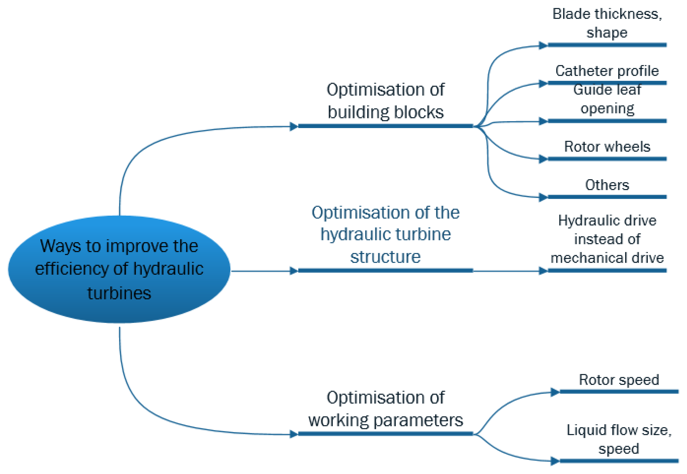
Figure 1 shows that methods to improve the efficiency of the hydraulic turbine optimize the hydraulic turbine mechanism, optimize the configuration of the device and adjust the system operating parameters. Optimization of components such as blade thickness, duct profile and guide vane opening can also be performed. Optimizing the configuration device can replace a mechanical transmission with a hydraulic transmission to reduce energy loss and improve transmission efficiency. Adjustment of the system operating parameters can maintain the hydraulic turbine operating condition in the high-efficiency zone.
The mechanical gearbox is one of the most failure-prone turbine components and is also the most expensive to replace and repair; replacing mechanical gears with hydraulic drives can increase efficiency and save costs [1].
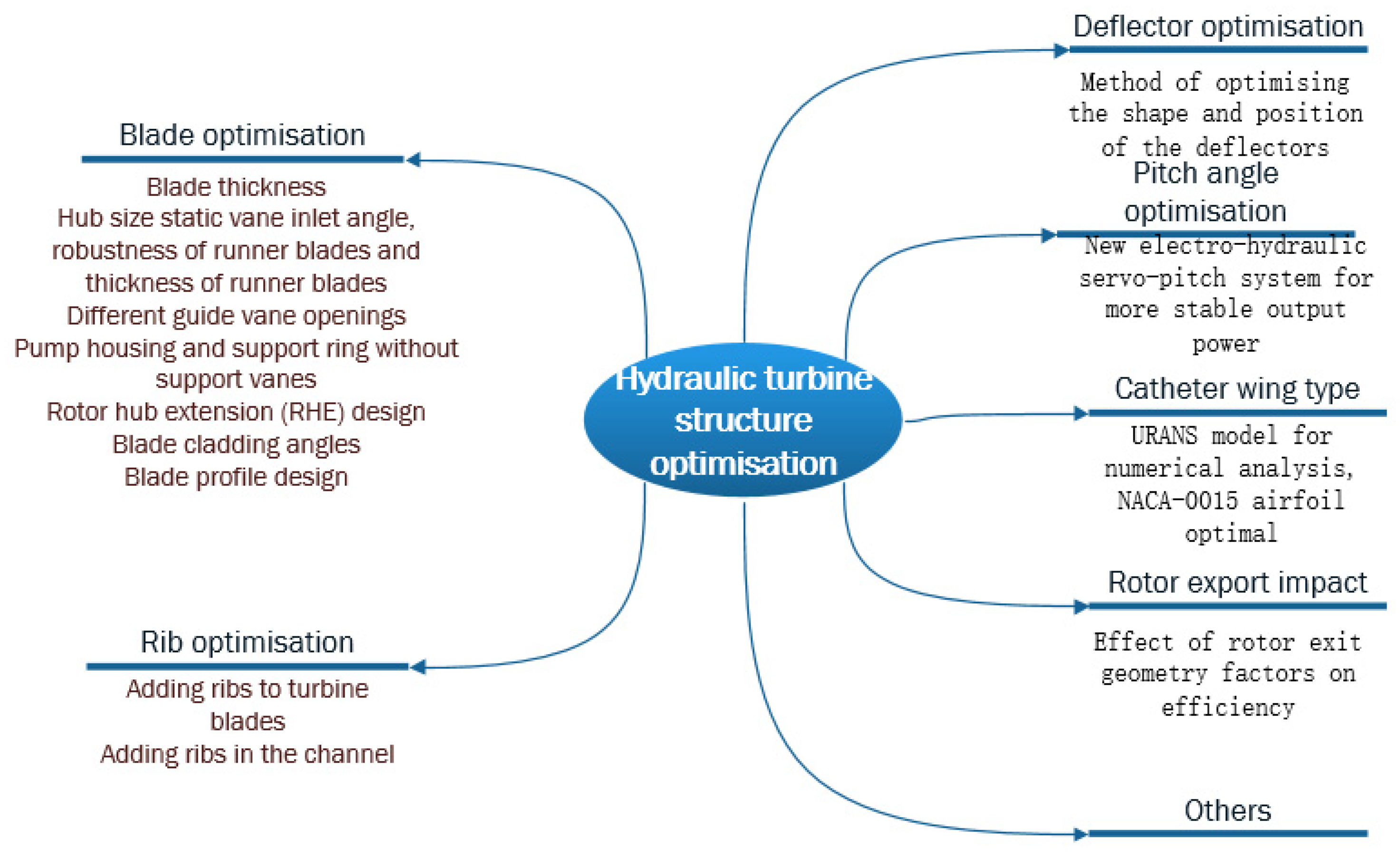
Figure 2 shows that the structural optimization of the hydraulic turbine includes the optimization of the blades, the addition of ribs or not, the optimization of the guide plate, and the optimization of the duct airfoil shape. For example, in blade optimization, simulation can be used to determine the optimal thickness and shape of the blade, and adding ribs to the turbine blade or channel can also optimize the structure to improve efficiency.
Energy recovery efficiency is improved by optimizing the structure. A three-dimensional Reynolds-averaged Navier–Stokes calculation was carried out using a shear stress transport turbulence model to analyze the internal flow characteristics near the rotor blades of different blade thicknesses to find the right blade thickness to meet the required hydraulic performance [2]. Each parameter of the hydraulic turbine affects the overall efficiency to a greater or lesser extent.
Various research methods, such as experimental simulation and simulation analysis, are used to optimize the blade structure and improve the overall efficiency [3,4,5,6]. The energy recovery efficiency is improved by modifying three aspects of the hub size: the stator stagger setting constants and the runner stagger setting constants. Blades with large twist angles increase blade complexity and blade manufacturing costs. Therefore, it is very important to define a minimum hub-to-tip ratio [7].
where is the initial guessed turbine efficiency, g is the standard gravity constant, is turbine general inclined angle, is the designed rotational speed in rad. This equation provides the initial guide for the turbine hub diameter design.
Traditional methods of calculating turbine efficiency cannot calculate the energy losses in the flow path. Entropy production theory allows the loss of irreversible energy to be analyzed and calculated visually. Yu [8] proposed an advanced entropy production diagnostic model (EPDM) with phase transition for assessing irreversible energy loss in cavitation flow and analyzing energy recovery efficiency. Chen [9] presented additional numerical simulations of several blade configurations, including static blade inlet angles, runner blade robustness and runner blade thickness, and the effects of these geometric configurations on overall performance and fluid behavior. Kerikous [10] proposed an optimization method to improve the shape and position of the front thick deflector of the Savonius turbine in order to increase the output of the energy recovery system. The flow of the spiral casing is limited to the discharge of cooling water, the output of the fan and the energy saving head of the cooling water system, so it has a low specific speed and the hydraulic losses of the spiral casing and the support ring are high, reducing the hydraulic efficiency. To improve efficiency, Zhang [11] designed a pump casing and support ring without support vanes. Das et al. [12] used passive control methods to modify the flow state within the turbine. The interaction of the altered vane tip leakage vortices with the local vortices generated by the stagnation grid, improved the reconnection flow at high flow coefficients and improved the turbine operating range by 33.3%.
To investigate the effect of ribs on turbine performance and efficiency improvements, Abbasi [13] added micron protrusions (ribs) similar to sharkskin to Wells turbine blades. Star CCM software was used to model the flow interaction with the Wells turbine to subdivide the effect on energy recovery efficiency [14,15,16]. Krishnaswamy [17]’s experimental analysis revealed that the use of ribs with the potential to produce high thermal hydraulic performance (THP) could increase the power output and efficiency of the turbine. Kerikous [18] maximized the output power by modifying the hydro Savonius turbine blade profile, involving 12 geometrical parameters in the shape optimization process.
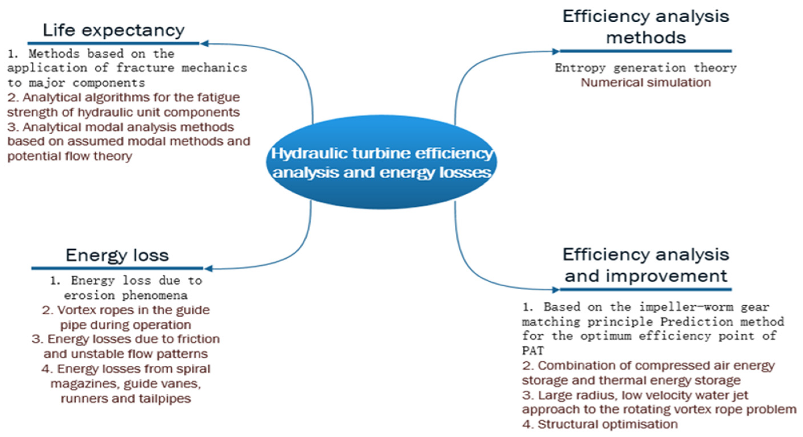
Figure 3 shows that the most common methods used to analyze the energy losses and efficiency of hydraulic turbines, which are numerical simulation and entropy generation theory. The energy loss of a hydraulic turbine can be caused by erosion, vortex rope phenomena and energy loss due to friction and unstable flow patterns. To ensure that the hydraulic turbine works safely, its life expectancy needs to be predicted. Commonly used methods are those based on the application of fracture mechanics to the most important components and the analysis of the fatigue strength of hydraulic unit components.
A variety of research methods, such as experimental simulation and simulation analysis, are used to study the energy loss of different types of hydraulic turbines under different operating conditions [19,20,21,22,23]. The main energy losses in the energy recovery process. Yu [24] applied entropy generation theory to turbine flow and quantitatively analyzed the hydraulic loss characteristics of the turbine. The authors used ANSYS CFX software to simulate the shear stress turbulence of a mixed flow turbine under different flow conditions. By comparing with experimental data, the energy losses of different flow components are analyzed, and the ability of the flow components to generate energy losses under different conditions is quantitatively evaluated. To study the problem of vortex ropes appearing in the lead pipe when the pump turbine is operated under non-design conditions, causing low pressure and low frequency fluctuations. Yu [25] studied the evolution of the vortex rope under typical operating conditions and its relationship with low-frequency pressure fluctuations to solve the problem of rotating vortex ropes caused by unstable flow in the inflow cylinder. Juposhti [26] studied the dynamics of water injection methods to mitigate RVR and the optimization of fire losses during water injection, using numerical simulations to investigate how to improve energy recovery efficiency. The study of overall efficiency has to be studied from multiple directions and perspectives [27,28,29]. Zou [30] used ANSYS CFX software to investigate multiphase flow in a turbine type. The main focus was to understand the mechanism of cavitation evolution and to reveal its correlation mechanism with flow instability. Yu et al. [31,32,33,34] conducted a comprehensive analysis of the flow losses of Francis turbines by the entropy production method and found that the hydraulic losses of turbines are closely related to flow separation, eddy motion and backflow. Meanwhile, the entropy yield of the guide tube accounted for the largest percentage, followed by the runner.
A life estimation algorithm is proposed to anticipate the life of the turbine, which can improve the efficiency of energy recovery. Georgievskaia [35] used a method of applying fracture mechanics to the main components of a hydraulic turbine, which takes into account construction and technical characteristics, operating modes and external loads. Another predictive system Georgievskaia [36] proposed implements analytical algorithms based on assessing the fatigue strength of hydraulic unit components under variable operating conditions and allows aggregation of damage for different external loads and different time periods, not only reducing the risk of accidents and unplanned downtime but also allowing intelligent maintenance of the turbine by developing the most efficient, rational and life-saving equipment strategies. In search of a simplified modeling tool for the design and prediction of the expected life of these turbines. Louyot proposed an analytical modal analysis method based on an assumed modal approach and potential flow theory and a modal force computational fluid dynamics (CFD) method. Both methods accurately predict intrinsic frequency splitting and intrinsic frequency drift with errors within the experimentally allowed limits [37,38,39,40].
Due to its excellent performance characteristics, the turbine energy recovery device has good potential for application in the reverse osmosis desalination process, inter-segment pressurization reverse osmosis wastewater treatment process, petrochemical hydrogenation process and other fields. In the future, turbine energy recovery devices should be serialized, integrated and standardized to improve their stability and efficiency, broaden their effective working range and improve their adaptability to changing working conditions.
Hydropower is a renewable energy source, with a globally installed hydropower capacity expected to grow by around 60% by 2050, reducing the burning of fossil fuels and thus greenhouse gas emissions, and meeting energy demand. The development of hydropower will create 600,000 professional jobs and is expected to require an investment of USD 1.7 trillion [41].
The study of improving the efficiency of energy recovery hydraulic turbines has great theoretical significance and economic value and can make a significant contribution to the economic construction of the country, reducing the energy consumption per unit of GDP and developing the theory of hydraulic machinery design.
The remainder of this overview is organized as follows. In Section 2, the effects of surface roughness and wear, speed and flow on efficiency are presented. Head and height have an effect on the flow rate. As the head increases, so does the flow rate, so it is important to choose the correct head and head height. In Section 3, the practical application and results of optimizing the structure or working parameters of the hydraulic turbine are introduced, especially the Box–Behnken Design method and NSGA-II genetic algorithm, which are used to optimize the centrifugal pump. Finally, Section 4 concludes the paper. By analyzing the effects of surface roughness, flow rate, head and impeller speed on overall efficiency, suitable optimization methods can be selected to optimize the structure and operating parameters of the hydraulic turbine and improve its efficiency.
2. Effect of Factors on the Efficiency of Hydraulic Turbines
2.1. Effects of Surface Roughness and Wear
Scientists have found that the roughness of the turbine through-flow section affects energy loss, fluid velocity distribution and pressure distribution. Brice and Kirkland et al. [42,43,44,45] found a similar relationship between the surface roughness of turbine through-flow components and the reduced efficiency of hydraulic turbines. In this context, surface roughness includes initial roughness that is dependent on the manufacturing technique used, as well as roughness that has changed due to wear or erosion. Thus, an increase in the surface roughness of the flow-through components can lead to an increase in energy loss during operation.
A gas turbine is used for natural liquefied gas. Replacing the traditional Joule–Thomson valve with hydraulic turbines can improve the energy and cost benefits of natural gas liquefaction. Compared with traditional SMR processes using Joule–Thomson valve valves, the recovered energy can increase the feed pressure of natural gas, save energy and improve efficiency [46,47,48,49]. The marine desulfurization tower is an emission reduction device widely used in ship transport. While reducing gas emissions, it also brings with it the problem of energy consumption, which cannot be ignored. With the solution of desulfurization using twin-suction turbines, the efficiency of the twin-suction turbines can reach more than 80%. Gas turbines for liquid rocket engines (LPREs) require high thrust, high specific impulse and high flow rates. Consequently, there are also stringent requirements for their components [50,51,52]. For turbine pumps (TPs), this means high flow rates, high rotational speeds and high pressure ratios, which make their operation vulnerable to cavitation, while clean, renewable energy sources such as hydropower play an increasingly important role in saving energy and reducing emissions [53,54,55,56,57]. As a hydraulic machine, energy losses from pumps and turbines are always present, and hydraulic turbines are used in many hydropower stations to generate electricity by recovering water with high pressure differences. With breakthroughs in related technologies, turbine design and performance analysis are two critical aspects of any hydroelectric power project, ensuring the economical and efficient operation of these plants. Variable renewable energy sources need to be used in parallel to quickly balance fluctuations in grid frequencies. To balance the fluctuation problem in the generation process, common solutions are: one method is that the auxiliary fluid injection consists of eliminating the stagnation zone that causes the rope to form by momentum transfer of the injected fluid at the proper location and velocity. This is typically accomplished using water. An alternative method is to introduce air for flow aeration [58,59,60].
Increased roughness increases losses due to increased friction losses (typically between the head and the worn surface) and offset from the optimal hydraulic profile [61].
Friction losses should be particularly significant, especially in the runner with the highest relative speed. As early as 1978, Kurokawa et al. [62] used theoretical and experimental methods to study the effect of roughness on the three-dimensional boundary layer flow on a closed rotating disk. In 1997, Kubota et al. [63] extracted specific hydraulic energy deficiency from the performance diagram of a model turbine with changed roughness to systematically study the influence of surface roughness on the Francis turbine. In 2007, Krishnamachar and Fay [64,65] combined analytical methods with actual data and provided a reasonably simple calculation to obtain a realistic estimate of the effect of roughness on the optimal efficiency of a Francis turbine. More recently, Maruzewski et al. [66,67,68,69] studied the specific losses of each component of a Francis turbine, which were estimated by CFD simulation. The results were obtained for different channel surface roughness heights. IEC (International Electrotechnical Commission), IAHR (International Hydraulic Research Association) and their working groups collected and analyzed a large amount of data from model and prototype turbines to calculate or scale different friction coefficients by upgrading IEC 60,995 and other proportional effect formulas.
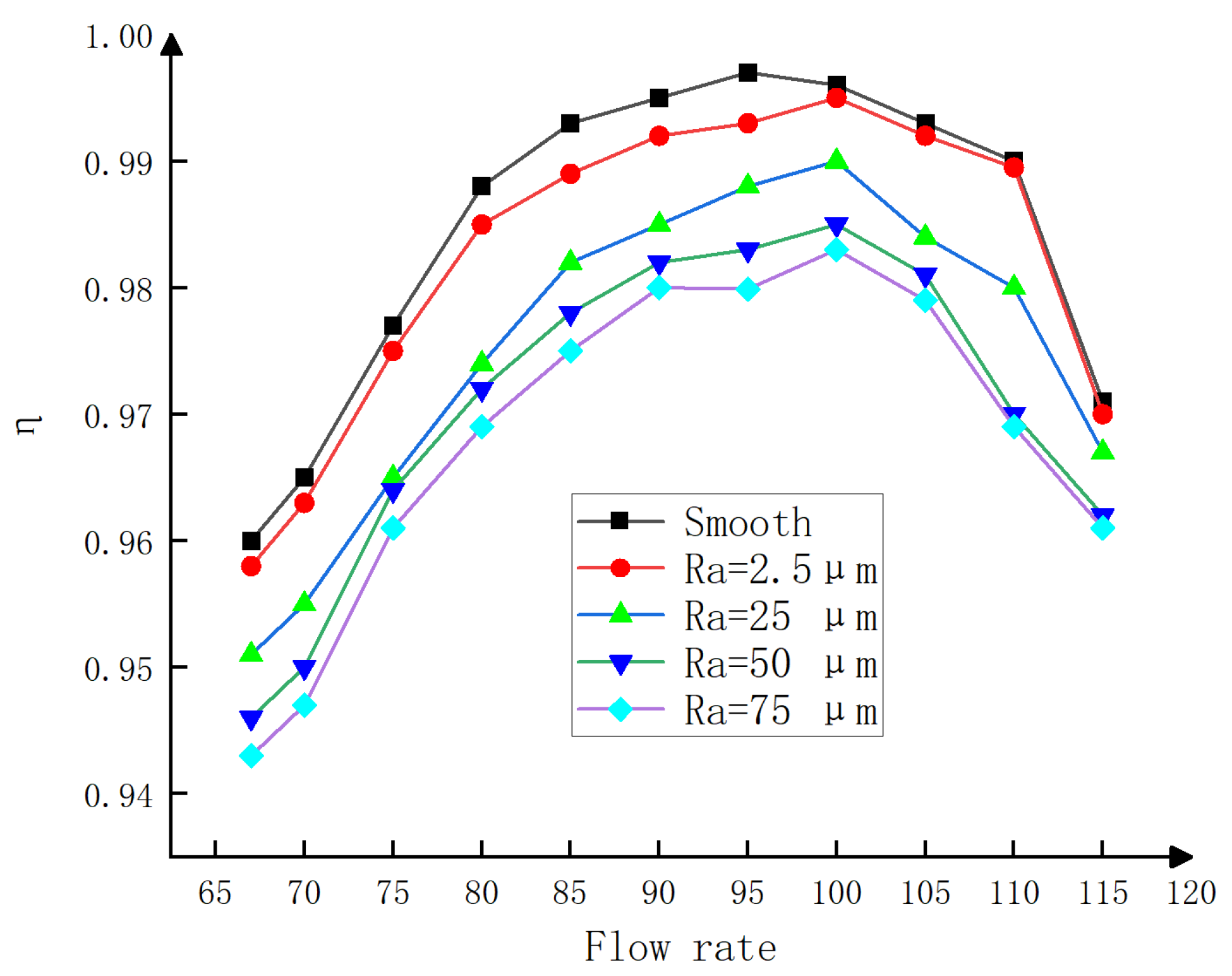
The relationship between the specific hydraulic energy efficiency and the surface roughness and flow rate is shown in Figure 4 [70]. The effect of surface roughness on turbine performance is carried out in a linear manner, increasing the grit roughness height from 2.5 μm to 75 μm. At the same surface roughness, the efficiency of the hydraulic turbine showed a trend of increasing and then decreasing with increasing flow rate. The efficiency of the hydraulic turbine at the same flow rate decreases with increasing surface roughness. We note that this efficiency does not decrease rapidly with increasing roughness.
The effect of wear on roughness was also significant. Truscott investigated the factors and types of wear and the impact of wear on performance and service life. Padhy and Saini [71,72,73] reviewed the different reasons for the decline in turbine performance and efficiency and the appropriate remedial measures proposed by various investigators based on literature surveys covering various aspects of turbine sediment erosion. In the worn bucket, the boundary layer thickens and is disturbed due to the increase in surface corrugations.
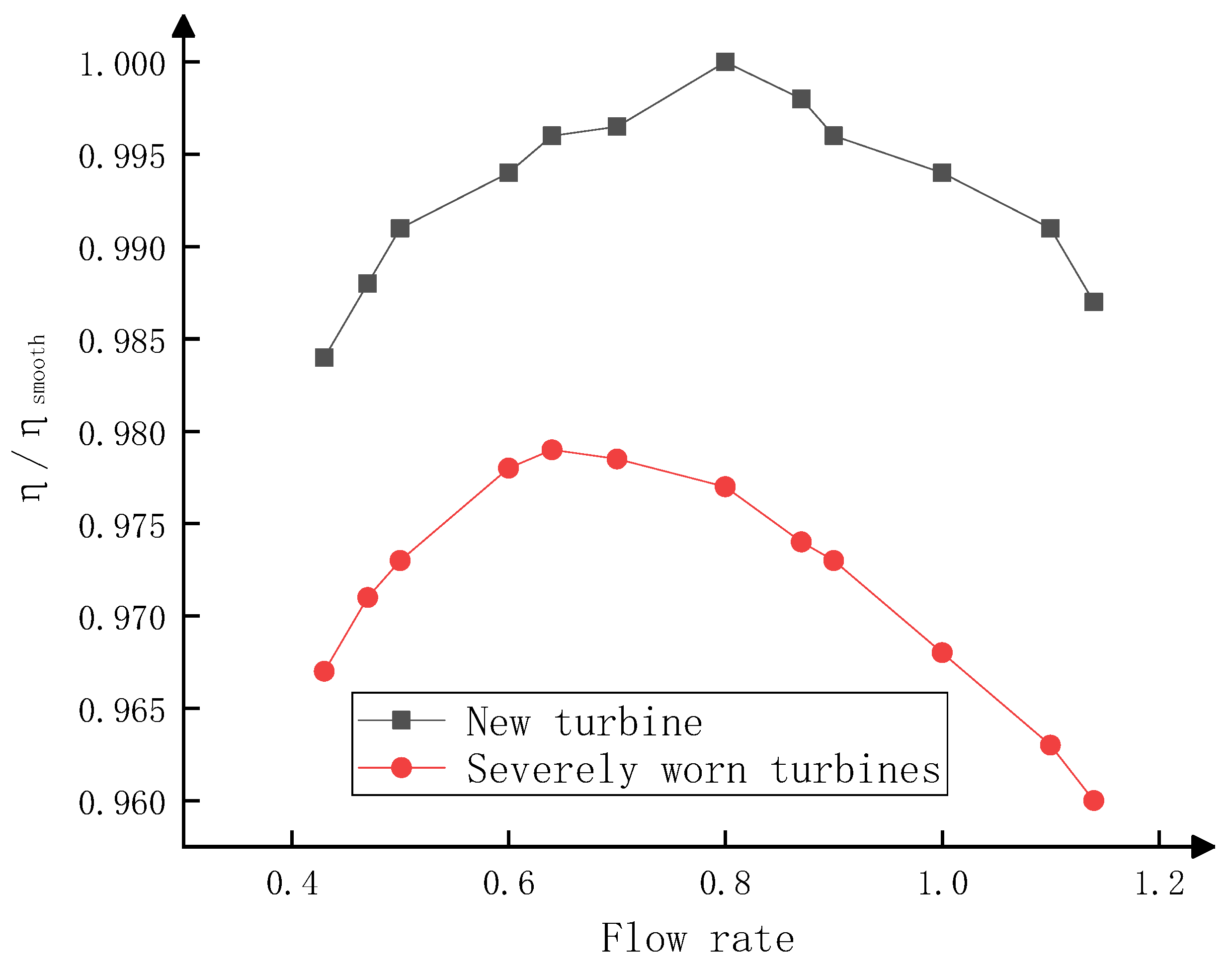
For reaction turbines, the performance of the turbine is destined to decline over time for various reasons, as shown in Figure 5. These factors include metal loss (cavitation, erosion and corrosion), runner seal openings, guide vane gap openings and increased surface roughness. Erosion wear due to high abrasive content is very important wear during monsoon and cavitation [74].
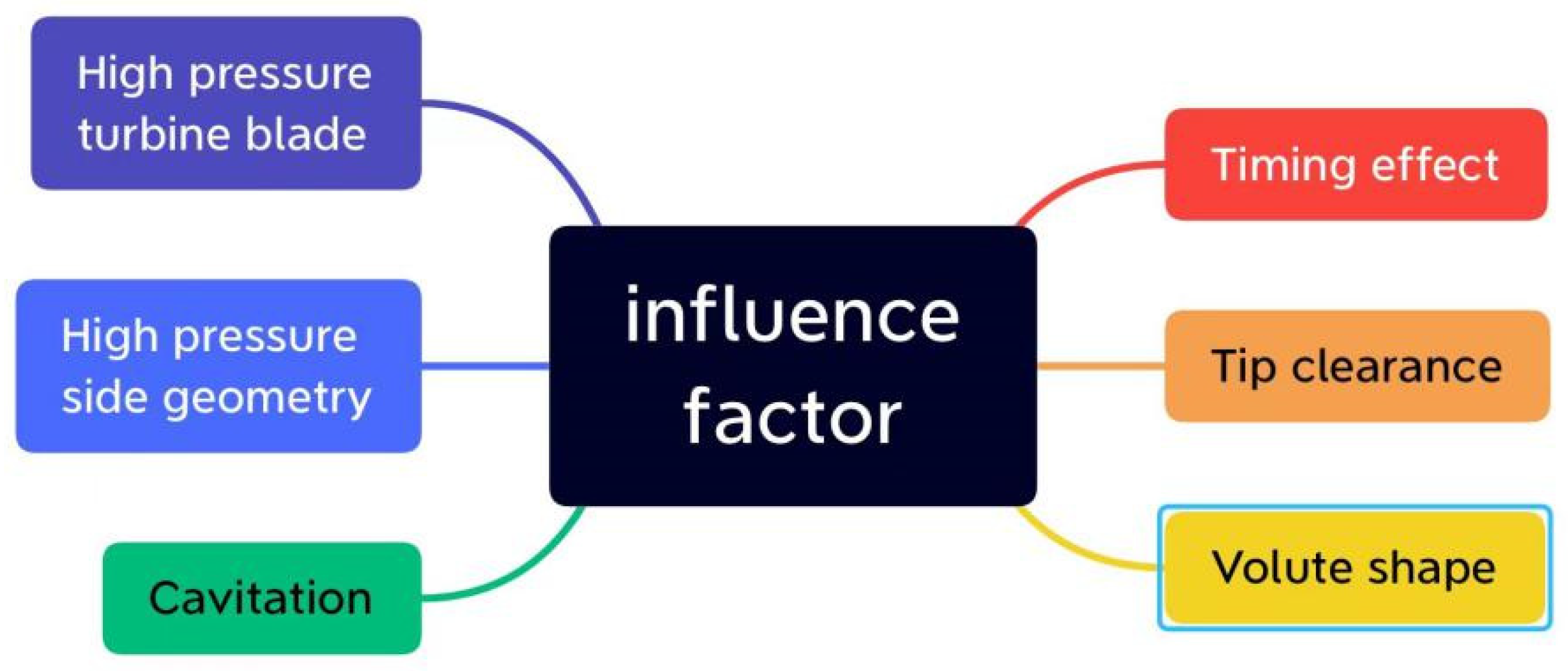
Figure 6 shows that cavitation occurs when pressure drops below the steam pressure and is a major problem for hydraulic reaction turbines because it can damage turbine components, affect turbine performance and increase maintenance costs. The service life of a gas turbine engine mainly depends on the service life of high-pressure turbine blades. The impact of high-pressure and high-temperature gas on moving rotor blades will lead to various failure mechanisms along the blade contour, thus affecting the operation efficiency of the gas turbine. The geometry of the high-pressure side of the blade has an important influence on the performance of the pump turbine under both design and non-design conditions. If the pump and turbine modes are optimized, the optimized runner can significantly reduce hydraulic loss in the downstream area of the high-pressure side. The geometry of the high pressure side of the blade has a significant influence on hydraulic loss. The energy loss at the same flow rate is mainly concentrated on the guide vane, volute and runner, accounting for 49.73–58.07%, 20.13–22.45% and 16.81–23.23% respectively. The wall effect and velocity fluctuation are the main factors contributing to the generation of entropies, accounting for more than 98% in total. A comparison of wall entropy generation rates and wall shear forces shows that wall shear stress has a direct effect on the energy loss of guide vanes and impeller blades. Shocks, backflows and vortices are the main contributors to irreversible energy losses. The flow and torque mechanisms inside the turbine can be explained by stagnation pressure on the concave side of the blade at small angles to the blade position and coaxial flow on the convex side, which then creates a high-speed zone inside the turbine, which impinges on the downstream blade at a large angle. These flow field changes produce increased local torque at small angles and moderate torque at large angles. By optimizing the impeller blade top clearance and the turbine blade tip speed ratio, the turbine can be made more efficient, which is verified by observing the correspondence between the flow velocity in the turbine and the different blade position angles.
Through the above discussion, we analyze the influence of surface roughness and wear on the efficiency of turbines. Based on the analysis, we can grind, coat or spray wet surfaces, which can improve surface roughness and wear resistance. This also helps maintain and extend the lives of these structures [75].
- For turbines, adequate needle and nozzle coatings are relatively inexpensive to maintain performance, helping to maintain the quality and compactness of the injection. For a mixed flow turbine, the condition of its components is much more complex than that of Pelton. Coating the static/dynamic sealing rings, guide vanes (with wear plate) and the inlet and outlet edges of the runners keeps the turbine in good condition. In some cases, field tests have shown that the efficiency of pre-coating is improved by 0.1~0.8% compared with post-coating.
- The application of new materials is another effective method for improving surface properties. Use suitable, mature materials, such as stainless steel and coatings of newly invented materials, to manufacture turbine components to maximize resistance to erosion, abrasive wear and cavitation, and to extend life. If sediments contain hard minerals, such as quartz, the abrasion of steels, such as guide vanes and flow paths, can become very large and can quickly reduce efficiency or completely destroy the turbine in a very short time. New solutions are being developed to coat steel with very hard ceramic coatings to prevent erosion or delay the process.
- In addition, reducing the surface roughness (i.e., reducing friction resistance) of the inner surface of the pressure pipe by using new coating materials will help reduce head loss through the system and thus improve efficiency.
2.2. Influence of Speed and Flow Rate on Efficiency
The RPM was tested at different running blade opening angles and flow rates. Each flow rate shows its optimal rotational speed, increasing as the flow rate increases to maintain the velocity triangle and accommodate larger flows. Turbine efficiency is a parabola in speed ratio and maximum efficiency occurs when the speed ratio is between 0.9 and 1. In order to maintain high efficiency at low flow ratios, the nozzle design must ensure that the lower flow remains in the deflector [76].
Goodarz Mehr [76] introduced a new method for the design and optimization of hydrodynamic flow turbines for various operating conditions. This method not only decomposes and simplifies the design process into well-defined steps but also allows numerical simulations of individual turbines. The design process includes designing the geometry of the guide vane, optimizing the impeller speed parameters and improving the performance of the turbine by analyzing various load conditions. In a simulation case study, a turbine designed using the new method has a peak hydraulic efficiency of 91% and a peak overall efficiency of 82% at volumetric flows as low as 14% of nominal value and head variations as high as 30% of nominal value.
Vivas [77] chose a new flow-head coefficient as the main dimensionless coefficient by studying the effect of flow and head on efficiency. From the five commonly used input design parameters, the values of three parameters were selected and allowed to vary for two to meet the design needs, and the designed and simulated turbine showed a maximum hydraulic efficiency of 65%.
From the above discussion, it can be seen that speed and flow have a direct impact on efficiency. If the best speed and flow for the system are determined by appropriate design methods, the overall efficiency will be greatly improved.
2.3. Efficiency vs. Head
The efficiency does not decrease significantly when the head is higher than the optimal head (the head determines the optimal efficiency at a given rotational speed), while the efficiency decreases sharply when the head is smaller. The optimal RPMN depends on head H, which is the result of the increased velocity of the runner passing through the head [78]. The geometric parameters of the impeller are the main factors affecting the hydraulic performance of the turbine. The hydraulic performance of the turbine is different from that of the pump. The hydraulic performance of a turbine is different from that of a pump because a turbine is a pump that rotates in reverse. Then, in order to predict the turbine performance at the optimal efficiency point of the pump, the turbine performance at the optimal efficiency point of the pump is required; the flow rate and head of the turbine with optimal performance can be obtained through the calculation of the Sharma relationship.
where and are the flow rate and head of the turbine, respectively, and are the flow rate and head of the pump, respectively, and is the optimal efficiency of the pump.
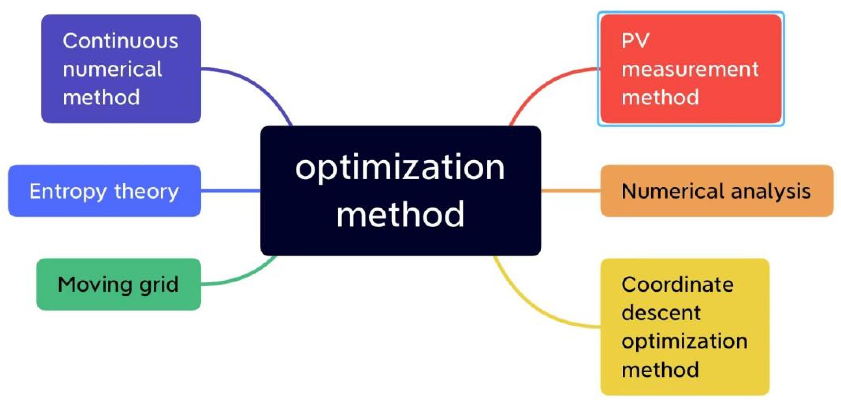
Figure 7 shows that the unsteady flow field around the turbine was measured in an open water tunnel using phase-averaged particle image velocimetry and compared to the results of a two-dimensional numerical simulation using the volume of fluid method for two-phase flow analysis. By reducing the bottom spacing, these flow characteristics were improved, contributing to local torque generation. Therefore, the torque performance and efficiency of the cross-flow turbine improved. However, very small bottom spacing may not be an effective way to improve efficiency. The process is decomposed into clearly defined steps and simplified by a three-step continuous numerical method. Once a single turbine is numerically simulated, most of the results can be applied to the entire cross-flow turbine. The turbine designed with this process achieves 91% peak hydraulic efficiency and 82% peak total efficiency, with volume flow as low as 14% of nominal value and head variation as high as 30% of nominal value. The entropy generation theory was introduced to analyze the drop method of the hydraulic loss distribution of PAT to make the numerical simulation results more consistent with the hydraulic performance test results. Dynamic grid technology in CFD is used to make the simulated situation more realistic, and the flow field changes and operation characteristics inside the gas turbine can be better represented by the optimization of the simulation. The main purpose of this research is to discuss boundary conditions and turbulence models that capture different hydrodynamic phenomena in turbine design and non-design operation. Critical review of various calculation methods is necessary to achieve different objectives for turbine hydraulic design and performance evaluation. The hydraulic turbine governance system (HTGS) is a complex non-linear time-delayed system and stability control is an important factor in the safe operation of hydroelectric units. Control focusing on Liapunov asymmetrically stabilized HTGSs may suffer from poor transient performance, and external disturbances may also make control unsatisfactory. Numerical simulation results show that it provides a better method for stability control of HTGS for practical engineering applications [79,80].
Head and height have a certain effect on the flow rate. With the increase of head, the flow will also increase, as will the best flow path for evil and the final efficiency. Therefore, it is very important to select the right head and head height.
3. Optimization of Hydraulic Turbine
3.1. Effect of Structure and Working Parameter Optimization on the Efficiency of Hydraulic Turbine
As the core mechanical equipment of water energy development, the performance of a water turbine determines the utilization rate of water energy development. Driven by the progress of modern science and technology, turbine technology has also made great progress. By studying the optimization of steam turbine running parameters and structural parameters, the steam turbine can keep running continuously in the high efficiency zone and improve system efficiency [81,82,83,84,85,86].
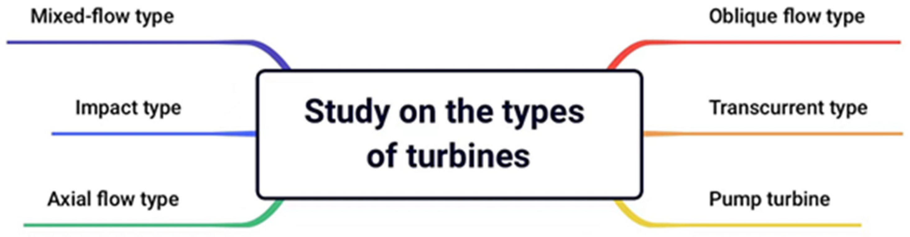
Figure 8 shows that turbine pumps on the market mainly include mixed-flow type, impact type, axial flow type, oblique flow type, transcurrent type and pump turbine. Each turbine pump has its own advantages and disadvantages. For example, the mixed-flow pump head is higher than the axial flow pump, but the flow is smaller than the axial flow pump and larger than the centrifugal pump, and the inclined flow pump covers less area, has a small diameter, is easy to start and has high efficiency. Axial flow pumps are mainly suitable for low head, large flow occasions, such as irrigation, drainage, dock drainage, canal lock water level regulation, or as large circulating water pump power plants. The hydraulic action of different turbines can cause serious problems (e.g., abnormal shutdowns due to excessive machine vibrations), and the production determines which kind of pump is needed according to the actual situation [87,88].
As the core mechanical equipment of water energy development, the performance of a water turbine determines the utilization rate of water energy development. With the advancement of modern science and technology, the calibration technology of hydraulic turbines has made great progress. By optimizing the operation parameters and structural parameters of the steam turbine, the steam turbine can keep running continuously in the high efficiency zone and improve system efficiency [89,90,91]. Verbeek [92] found that the power coefficient of the turbine could be improved by optimizing the degree of blockage of the channel and the distance between the turbine and the structure, which was related to wake configuration. As a result, when the turbine is repositioned from the upstream end of the structure to the downstream end, the power coefficient improves by 40%. Han et al. [93,94] reduced the internal energy loss and improved the working efficiency and service life of the hydraulic turbine by optimizing the structure of the valve distributor, bifurcated pipe and nozzle.
Performance prediction of the hydraulic turbine multistage centrifugal pump. At present, research on the performance prediction and structure optimization of multi-stage hydraulic turbine pumps mostly adopts a numerical simulation method, and the single-stage pump is used for reference in theory [95,96]. However, the design principles of the two are not exactly the same. Therefore, it is of great significance to study the turbulence theory and structure optimization of a multistage centrifugal pump to improve its working performance [97,98,99].
The influence of medium temperature on prediction accuracy and the influence of medium property change caused by temperature change on turbine performance cannot be ignored. Working efficiency can be improved by optimizing the working parameters of hydraulic turbines [100,101,102].
There are three main types of hydraulic turbine pumps: one is a hydraulic turbine pump, one is a reverse hydraulic pump, and one is a new type of hydraulic pump. Hydraulic turbine pumps with high comprehensive performance and good adaptability are widely used in enterprises. The reverse hydraulic pump is relatively simple to operate, widely used, economical and practical, and performs well in production. The new hydraulic pump is easy to use, has a higher overall performance, and can optimize the overall structure. Each pump has its own advantages, and the specific choice depends on the situation.
Whether in aerospace or hydroelectric power generation, where the hydraulic turbine is a critical part, Luiz Henrique Lindquist Whitacker et al. [103,104,105] used simulation to verify the effect of parameters, such as blade structure and the top clearance of the blade, on efficiency, providing a new approach for future research in numerical simulation. Elena-Maria et al. [106] reduced the impact of hydraulic turbines on the environment by improving the structure, and Rahimilarki et al. [107,108] improved the efficiency of fault detection by using neural network algorithms to ensure safe operation. Delgado [109] proposed a new two-step method based on Hermite polynomial chaotic expansion to predict the characteristic curve of a pump operating as a hydraulic turbine and to model its variable speed operation so as to improve the prediction accuracy. The proposed predictive agent function and variable speed mountain map model are useful engineering tools for improving the design of pumps as turbine hydropower stations and for optimizing the operation of pumps as turbine control settings to maximize the energy generated.
3.2. Optimization of Turbine by the Box–Behnken Design Method
To improve turbine efficiency, Ji et al. [110] combined the BBD response surface method with CFD numerical simulation to obtain an optimal turbine model. The Sharma relation between the flow and head maximum performance of the turbine was calculated to predict the turbine performance at the optimum pump efficiency point. In the test, the impeller blade outlet angle, blade inlet angle and blade thickness are taken as the influence factors of the BBD test, and the water head and efficiency are taken as the evaluation indicators. The response surface test design and results are shown in Table 1. Through variance analysis of the quadratic linear model of turbine blade efficiency, the turbine efficiency is mainly influenced by the blade inlet angle and not by the outlet angle and blade thickness.
In addition, Ji et al. [110] completed the calculation model and verification of grid independence. By analyzing the external characteristic curve of the turbine, the performance of the model is optimized, and the efficiency is improved. In a comparative analysis of the turbine flow field, optimizing the turbine inlet and outlet pressures reduces energy loss. The velocity field of the optimized model can make the turbine speed change slowly and the flow stable and improve the hydraulic performance of the turbine.
3.3. Multi-Objective Parameter Optimization of Turbine Impeller Based on the RBF Neural Network and NSGA-II Genetic Algorithm
Ji et al. [111] proposed a radial basis function (RBF) neural network combined with an NSGA-II genetic algorithm for multi-objective optimization of the PAT impeller in order to improve the efficiency of a centrifugal pump as a turbine (PAT). A Plackett–Burman screening test was used to screen the geometric parameters affecting the turbine impeller and a Latin experimental design method was used to sample the selected significant influences. An RBF neural network was used to fit the mapping relationship between the optimization variables and the optimization objectives, and the NSGA-II genetic algorithm was used for multi-objective optimization. The results showed that the efficiency and competence of the optimized model were improved by 5.74% and 4.85%, respectively, compared to the original model.
In Figure 9, pumps and turbines are reversible. However, in engineering practice, the working conditions and operation modes of pump and steam turbines are very different. If the design method of the pump is directly applied to the design of the steam turbine, the efficiency of the steam turbine is generally low, the service life is shortened, and the energy cannot be effectively recovered. Therefore, it is found that there is a certain conversion relationship between the pump and steam turbine.
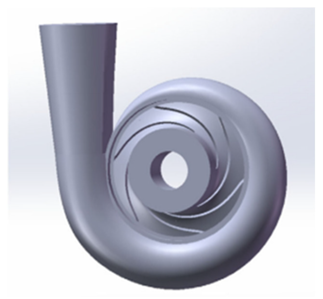
The model calculation domain is shown in Figure 10 and includes the impeller flow path and the vortex flow path. The impeller runners are meshed by Turbogrid in ANSYS.
Many parameters affect turbine performance. In order to clarify the significant influencing parameters, Design Expect 10 software was used to design the Plackett–Burman screening test for the geometrical parameters of the turbine, taking the water head and efficiency of the turbine as optimization objectives. Six geometric parameters, including inlet angle, outlet angle, winding angle, inlet width, outlet diameter and blade thickness, were selected. The above values are about 0.8 times and 1.2 times the original geometric parameters, respectively, and a total of 12 tests were carried out. The corresponding efficiency and headers of 12 groups of samples were simulated using Ansys-CFX software, and the results were analyzed using Design Expect 10 software. The analysis results show that inlet placement angle, winding angle, and inlet width are important parameters affecting turbine performance.
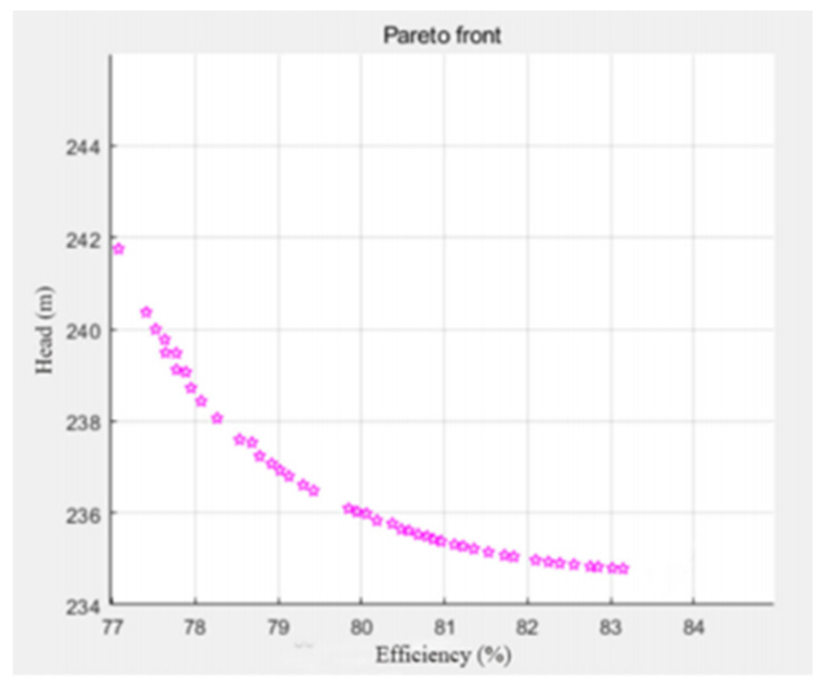
When the NSGA-II genetic algorithm is used for global optimization, the population size is defined as 200, the maximum genetic algebra is 100, and the crossover probability is 0.9. The Pareto front figure optimized by the NSGA-II genetic algorithm is shown in Figure 11. On the basis of ensuring turbine water head, the Pareto front’s three optimal efficiency solutions are selected. The best efficiency was 83.34%, and the corresponding head was 234.37 m.
The optimization results show that compared to the original model, the optimized model reduces the inlet angle Bt by 2.64, the wrap angle (by 33.15° and the inlet width by 0.97 mm). At the design working point, the optimized model is 5.74% more efficient than the original model and has a 5.74% higher head than the original model.
4. Conclusions
Hydraulic turbine energy recovery devices are widely used, and their research has developed in the direction of specialization, specialization and diversification.
- (1)
- Improving the efficiency of a hydraulic turbine can be regulated in three ways: the structural performance of the turbine itself, the configuration of the recovery unit and the operating conditions. The methods used to analyze the energy loss and efficiency of a hydraulic turbine are numerical simulation and entropy generation theory. The conditions that cause energy losses in hydraulic turbines are erosion, vortex rope phenomena and energy losses due to friction and unstable flow patterns.
- (2)
- With the increase in head, the pump flow and output power increase, and the trend is first rise and then a small decline, mainly at the impeller, followed by the worm gear and discharge pipe area. The pump showed obvious hump characteristics in the low flow area, and the hydraulic efficiency increased and then decreased with the flow rate. The main reason for the hydraulic loss in the low-flow condition is the vortex flow and the flow separation in the suction surface at the impeller, and the hydraulic loss in the impeller domain gradually decreases with the increase of the flow rate. The main reason for the hydraulic loss in the high-flow condition is the secondary flow in the worm gear and the turbulent flow in the outlet pipe. The lift coefficient of the pump decreases with the increase of roughness. The increase of the inlet angle will make the influence of roughness on the impeller increase to a certain extent, and the lift coefficient and drag coefficient of the impeller are distributed as a periodic function of time.
- (3)
- Different turbines and different working conditions can adopt different optimization methods. The optimization methods described in detail in this paper are Box–Behnken Design method and the NSGA-II genetic algorithm. By optimizing the inlet angle, outlet noise, blade thickness and other adjustments are made. Compared with the data of the original model, the distribution of pressure, turbulent kinetic energy and velocity in the flow are significantly improved.
The conclusion is that a lot of work needs to be done to understand the working conditions of the hydraulic turbine under various working conditions, to use a variety of multi-objective optimization methods to optimize the design, and to improve the work efficiency and prolong the working life. Developing a more efficient hydraulic turbine or better optimization methods is an important direction of future research.
Funding
The research was supported by the Program for the Introduction of Foreign Intellects in Hebei Prov (2022) “Research on Key Technologies and Equipment of Efficient and Clean Power Generation for Carbon Neutralization” (No. 20220701).
Data Availability Statement
The authors confirm that the data supporting the findings of this study are available within the article.
Acknowledgments
This research was supported by the Natural Science Foundation of Hebei Province (No. E2021208004) and the Program for the Introduction of Foreign Intellects in Hebei Prov. (2022). This research was supported by the Foundation of State Key Laboratory of Public Big Data (No. PBD2021-06) and Guizhou optoelectronic information and intelligent application International Joint Research Center (Qiankehe platform talents No. 5802[2019]).
Conflicts of Interest
The authors declare that they have no known competing financial interests or personal relationships that could have appeared to influence the work reported in this paper.
References
- Roggenburg, M.; Esquivel-Puentes, H.A.; Vacca, A.; Evans, H.B.; Garcia-Bravo, J.M.; Warsinger, D.M.; Ivantysynova, M.; Castillo, L. Techno-economic analysis of a hydraulic transmission for floating offshore wind turbines. Renew. Energy 2020, 153, 1194–1204. [Google Scholar] [CrossRef]
- Kim, S.-J.; Choi, Y.-S.; Cho, Y.; Choi, J.-W.; Kim, J.-H. Effect of blade thickness on the hydraulic performance of a Francis hydro turbine model. Renew. Energy 2019, 134, 807–817. [Google Scholar] [CrossRef]
- Kaur, I.; Singh, P.; Ekkad, S.V. Enhanced thermal hydraulic performance by V-shaped protrusion for gas turbine blade trailing edge cooling. Int. J. Heat Mass Transf. 2020, 149, 119221. [Google Scholar] [CrossRef]
- Song, R.; Wu, Y.; Lin, Z.; Ren, C.; Fang, S. Study on the influence of blade profile on hydraulic Savonius turbine under wave action. Ocean Eng. 2021, 240, 109863. [Google Scholar] [CrossRef]
- Bai, Y.; Kong, F.; Yang, S.; Chen, K.; Dai, T. Effect of blade wrap angle in hydraulic turbine with forward-curved blades. Int. J. Hydrogen Energy 2017, 42, 18709–18717. [Google Scholar] [CrossRef]
- Jin, W.; Jia, Y.X.; Lei, J.; Ji, W.T.; Wu, J.M. Coupled heat transfer analysis of internal and film cooling of turbine blade under medium temperature conditions. Appl. Therm. Eng. 2022, 214, 118792. [Google Scholar] [CrossRef]
- Chen, J.; Engeda, A. Standard module hydraulic technology: A novel geometrical design methodology and analysis for a low-head hydraulic turbine system, Part I: General design methodology and basic geometry considerations. Energy 2020, 196, 112–136. [Google Scholar] [CrossRef]
- Yu, A.; Tang, Q.; Zhou, D.; Liu, J. Numerical investigation of the energy evaluation in a Francis turbine based on an advanced entropy production model. Int. Commun. Heat Mass Transf. 2021, 129, 12–26. [Google Scholar] [CrossRef]
- Chen, J.; Engeda, A. Standard module hydraulic technology: A novel geometrical design methodology and analysis for a low-head hydraulic turbine system, part II: Turbine stator-blade and runner-blade geometry, and off-design considerations. Energy 2021, 214, 118–131. [Google Scholar] [CrossRef]
- Kerikous, E.; Thévenin, D. Optimal shape and position of a thick deflector plate in front of a hydraulic Savonius turbine. Energy 2019, 189, 116–133. [Google Scholar] [CrossRef]
- Zhang, L.; Ren, Y.; Li, Y.; Chen, D. Hydraulic Characteristic of Cooling Tower Francis Turbine with Different Spiral Casing and Stay Ring. Energy Procedia 2012, 16, 651–655. [Google Scholar] [CrossRef] [Green Version]
- Islam, N.; Das, T.K.; Samad, A.; Pasha, A.A. Passive Flow Control via Tip Grooving and Stall Fencing Mechanisms of a Marine Energy Harvesting Turbine. Sci. Rep. 2023, 13, 2677. [Google Scholar] [CrossRef]
- Abbasi, R.; Ketabdari, M.J. Enhancement of OWC Wells turbine efficiency and performance using riblets covered blades, a numerical study. Energy Convers. Manag. 2022, 254, 115–123. [Google Scholar] [CrossRef]
- Lund, H.; Mathiesen, B.V. Energy system analysis of 100% renewable energy systems—The case of Denmark in years 2030 and 2050. Energy 2009, 34, 524–531. [Google Scholar] [CrossRef]
- López, I.; Carballo, R.; Iglesias, G. Intra-annual variability in the performance of an oscillating water column wave energy converter. Energy Convers. Manag. 2020, 207, 112536. [Google Scholar] [CrossRef]
- López, I.; Carballo, R.; Iglesias, G. Site-specific wave energy conversion performance of an oscillating water column device. Energy Convers. Manag. 2019, 195, 457–465. [Google Scholar] [CrossRef]
- Krishnaswamy, K.; Sivan, S. Improvement in thermal hydraulic performance by using continuous V and W-Shaped rib turbulators in gas turbine blade cooling application. Case Stud. Therm. Eng. 2021, 24, 100857. [Google Scholar] [CrossRef]
- Kerikous, E.; Thévenin, D. Optimal shape of thick blades for a hydraulic Savonius turbine. Renew. Energy 2019, 134, 629–638. [Google Scholar] [CrossRef]
- Koirala, R.; Thapa, B.; Neopane, H.P.; Zhu, B. A review on flow and sediment erosion in guide vanes of Francis turbines. Renew. Sustain. Energy Rev. 2017, 75, 1054–1065. [Google Scholar] [CrossRef]
- Doshi, A.; Channiwala, S.; Singh, P. Inlet impeller rounding in pumps as turbines: An experimental study to investigate the relative effects of blade and shroud rounding. Exp. Therm. Fluid Sci. 2017, 82, 333–348. [Google Scholar] [CrossRef]
- Ahn, S.-H.; Xiao, Y.; Wang, Z.; Zhou, X.; Luo, Y. Performance prediction of a prototype tidal power turbine by using a suitable numerical model. Renew. Energy 2017, 113, 293–302. [Google Scholar] [CrossRef]
- Irizar, V.; Andreasen, C.S. Hydraulic pitch control system for wind turbines: Advanced modeling and verification of an hydraulic accumulator. Simul. Model. Pract. Theory 2017, 79, 1–22. [Google Scholar] [CrossRef] [Green Version]
- Vasanthakumar, P.; Krishnaraj, J.; Karthikayan, S.; Vinoth, T.; Sankar, S.K.A. Investigation on Reverse Characteristics of Centrifugal Pump in Turbine Mode: A Comparative Study by An Experimentation and Simulation. Mater. Today Proc. 2017, 4, 693–700. [Google Scholar] [CrossRef]
- Yu, A.; Tang, Y.; Tang, Q.; Cai, J.; Zhao, L.; Ge, X. Energy analysis of Francis turbine for various mass flow rate conditions based on entropy production theory. Renew. Energy 2022, 183, 447–458. [Google Scholar] [CrossRef]
- Yu, A.; Wang, Y.; Tang, Q.; Lv, R.; Yang, Z. Investigation of the vortex evolution and hydraulic excitation in a pump-turbine operating at different conditions. Renew. Energy 2021, 171, 462–478. [Google Scholar] [CrossRef]
- Juposhti, H.J.; Maddahian, R.; Cervantes, M.J. Optimization of axial water injection to mitigate the Rotating Vortex Rope in a Francis turbine. Renew. Energy 2021, 175, 214–231. [Google Scholar] [CrossRef]
- Rai, A.K.; Kumar, A. Analyzing hydro abrasive erosion in Kaplan turbine: A case study from India. J. Hydrodyn. Ser. B 2016, 28, 863–872. [Google Scholar] [CrossRef]
- Fan, Y.; Mu, A.; Ma, T. Study on the application of energy storage system in offshore wind turbine with hydraulic transmission. Energy Convers. Manag. 2016, 110, 338–346. [Google Scholar] [CrossRef]
- Kang, M.-W.; Park, N.; Suh, S.-H. Numerical Study on Sediment Erosion of Francis Turbine with Different Operating Conditions and Sediment Inflow Rates. Procedia Eng. 2016, 157, 457–464. [Google Scholar] [CrossRef] [Green Version]
- Yu, A.; Zou, Z.; Zhou, D.; Zheng, Y.; Luo, X. Investigation of the correlation mechanism between cavitation rope behavior and pressure fluctuations in a hydraulic turbine. Renew. Energy 2020, 147, 1199–1208. [Google Scholar] [CrossRef]
- Yu, Z.F.; Wang, W.Q.; Yan, Y.; Liu, X.S. Energy loss evaluation in a Francis turbine under overall operating conditions using entropy production method. Renew. Energy 2021, 169, 982–999. [Google Scholar] [CrossRef]
- Valentín, D.; Presas, A.; Valero, C.; Egusquiza, M.; Egusquiza, E.; Gomes, J.; Avellan, F. Transposition of the mechanical behavior from model to prototype of Francis turbines. Renew. Energy 2020, 152, 1011–1023. [Google Scholar] [CrossRef]
- Müller, A.; Favrel, A.; Landry, C.; Avellan, F. Fluid–structure interaction mechanisms leading to dangerous power swings in Francis turbines at full load. J. Fluids Struct. 2017, 69, 56–71. [Google Scholar] [CrossRef]
- Trivedi, C.; Gandhi, B.K.; Cervantes, M.J.; Dahlhaug, O.G. Experimental investigations of a model Francis turbine during shutdown at synchronous speed. Renew. Energy 2015, 83, 828–836. [Google Scholar] [CrossRef]
- Georgievskaia, E. Hydraulic turbines lifetime in terms of fracture mechanics. Eng. Fail. Anal. 2019, 105, 1296–1305. [Google Scholar] [CrossRef]
- Georgievskaia, E. Predictive analytics as a way to smart maintenance of hydraulic turbines. Procedia Struct. Integr. 2020, 28, 836–842. [Google Scholar] [CrossRef]
- Louyot, M.; Nennemann, B.; Monette, C.; Gosselin, F.P. Modal analysis of a spinning disk in a dense fluid as a model for high head hydraulic turbines. J. Fluids Struct. 2020, 94, 102965. [Google Scholar] [CrossRef] [Green Version]
- Presas, A.; Valentin, D.; Egusquiza, E.; Valero, C.; Seidel, U. Dynamic response of a rotating disk submerged and confined. J. Fluids Struct. 2016, 62, 332–349. [Google Scholar] [CrossRef] [Green Version]
- Presas, A.; Luo, Y.; Wang, Z.; Guo, B. Fatigue life estimation of Francis turbines based on experimental strain measurements: Review of the actual data and future trends. Renew. Sustain. Energy Rev. 2019, 102, 96–110. [Google Scholar] [CrossRef]
- Østby, P.T.; Sivertsen, K.; Billdal, J.T.; Haugen, B. Experimental investigation on the effect off near walls on the eigen frequency of a low specific speed francis runner. Mech. Syst. Signal Process. 2019, 118, 757–766. [Google Scholar] [CrossRef]
- Quaranta, E.; Davies, P. Emerging and Innovative Materials for Hydropower Engineering Applications: Turbines, Bearings, Sealing, Dams and Waterways, and Ocean Power. Engineering 2022, 8, 148–158. [Google Scholar] [CrossRef]
- Qyyum, M.A.; Ali, W.; Van Duc Long, N.; Khan, M.S.; Lee, M. Energy efficiency enhancement of a single mixed refrigerant LNG process using a novel hydraulic turbine. Energy 2018, 144, 968–976. [Google Scholar] [CrossRef]
- Arora, N.; Kumar, A.; Singal, S.K. Technological advancement in measurements of suspended sediment and hydraulic turbine erosion. Measurement 2022, 190, 110700. [Google Scholar] [CrossRef]
- Wang, T.; Shikama, H.; Yamagata, T.; Fujisawa, N. Experimental and numerical studies on flow and torque mechanisms of open cross-flow hydraulic turbine. Energy Sustain. Dev. 2021, 65, 107–116. [Google Scholar] [CrossRef]
- Goyal, R. Uncertainty estimation in calibration of instruments of model turbine test facility. Flow Meas. Instrum. 2021, 79, 101911. [Google Scholar] [CrossRef]
- da Silva Tonon, D.; Tomita, J.T.; Garcia, E.C.; Bringhenti, C.; Almeida, L.E.N. A parametric study of squealer tip geometries applied in a hydraulic axial turbine used in a rocket engine turbopump. Aerosp. Sci. Technol. 2022, 122, 107426. [Google Scholar] [CrossRef]
- Shikama, H.; Wang, T.; Yamagata, T.; Fujisawa, N. Experimental and numerical studies on the performance of a waterfall-type cross-flow hydraulic turbine. Energy Sustain. Dev. 2021, 64, 128–138. [Google Scholar] [CrossRef]
- Zhang, Z.; Su, X.; Jin, Y.; Zhu, Z.; Lin, T. Research on energy recovery through hydraulic turbine system in marine desulfurization application. Sustain. Energy Technol. Assess. 2022, 51, 101912. [Google Scholar] [CrossRef]
- Wang, L.; Li, B.; Chu, Z. Performance investigation of a novel thermosyphon based trilateral cycle using hydraulic turbine for power generation instead of two-phase expander. Appl. Therm. Eng. 2022, 211, 118441. [Google Scholar] [CrossRef]
- Antheaume, S.; Maître, T.; Achard, J.-L. Hydraulic Darrieus turbines efficiency for free fluid flow conditions versus power farms conditions. Renew. Energy 2008, 33, 2186–2198. [Google Scholar] [CrossRef]
- Quaranta, E.; Bahreini, A.; Riasi, A.; Revelli, R. The Very Low Head Turbine for hydropower generation in existing hydraulic infrastructures: State of the art and future challenges. Sustain. Energy Technol. Assess. 2022, 51, 101924. [Google Scholar] [CrossRef]
- Ghosh, S.; Kundu, B.; Ghosh, D.; Saha, K.; Chatterjee, I.; Ghosh, S. Thermal-Hydraulic analysis of axial gas turbine blade. Mater. Today Proc. 2022, 59, 1100–1104. [Google Scholar] [CrossRef]
- Velásquez, L.; Posada, A.; Chica, E. Optimization of the basin and inlet channel of a gravitational water vortex hydraulic turbine using the response surface methodology. Renew. Energy 2022, 187, 508–521. [Google Scholar] [CrossRef]
- Qin, Y.; Li, D.; Wang, H.; Liu, Z.; Wei, X.; Wang, X. Multi-objective optimization design on high pressure side of a pump-turbine runner with high efficiency. Renew. Energy 2022, 190, 103–120. [Google Scholar] [CrossRef]
- Tian, Y.; Wang, B.; Chen, P.; Yang, Y. Finite-time Takagi–Sugeno fuzzy controller design for hydraulic turbine governing systems with mechanical time delays. Renew. Energy 2021, 173, 614–624. [Google Scholar] [CrossRef]
- Xin, T.; Wei, J.; Qiuying, L.; Hou, G.; Ning, Z.; Yuchuan, W.; Diyi, C. Analysis of hydraulic loss of the centrifugal pump as turbine based on internal flow feature and entropy generation theory. Sustain. Energy Technol. Assess. 2022, 52, 102070. [Google Scholar] [CrossRef]
- Haghighi, M.H.S.; Mirghavami, S.M.; Ghorani, M.M.; Riasi, A.; Chini, S.F. A numerical study on the performance of a superhydrophobic coated very low head (VLH) axial hydraulic turbine using entropy generation method. Renew. Energy 2020, 147, 409–422. [Google Scholar] [CrossRef]
- Whitacker, L.H.L.; Tomita, J.T.; Bringhenti, C. Effect of tip clearance on cavitating flow of a hydraulic axial turbine applied in turbopump. Int. J. Mech. Sci. 2022, 213, 106855. [Google Scholar] [CrossRef]
- Yu, A.; Tang, Q.; Chen, H.; Zhou, D. Investigations of the thermodynamic entropy evaluation in a hydraulic turbine under various operating conditions. Renew. Energy 2021, 180, 1026–1043. [Google Scholar] [CrossRef]
- Khare, R.; Prasad, V. Prediction of cavitation and its mitigation techniques in hydraulic turbines—A review. Ocean Eng. 2021, 221, 108512. [Google Scholar] [CrossRef]
- Georgievskaia, E. Analytical system for predicting cracks in hydraulic turbines. Eng. Fail. Anal. 2021, 127, 105489. [Google Scholar] [CrossRef]
- Yang, R.-Y.; Wang, C.-W.; Huang, C.-C.; Chung, C.-H.; Chen, C.-P.; Huang, C.-J. The 1:20 scaled hydraulic model test and field experiment of barge-type floating offshore wind turbine system. Ocean Eng. 2022, 247, 110486. [Google Scholar] [CrossRef]
- Tiwari, G.; Kumar, J.; Prasad, V.; Patel, V.K. Utility of CFD in the design and performance analysis of hydraulic turbines—A review. Energy Rep. 2020, 6, 2410–2429. [Google Scholar] [CrossRef]
- Hu, J.; Yang, J.; Zeng, W.; Zhao, Z.; Yang, J. Hydraulic interaction of two parallel pump-turbines in constant-speed oscillation: Measurement, simulation, and sensitivity analysis. Renew. Energy 2021, 176, 269–279. [Google Scholar] [CrossRef]
- He, C.; Wang, J.; Wang, R.; Zhang, X. Research on the characteristics of hydraulic wind turbine with multi-accumulator. Renew. Energy 2021, 168, 1177–1188. [Google Scholar] [CrossRef]
- Sonawat, A.; Yang, H.-M.; Kim, J.-H. Experimental study of positive displacement hydraulic turbine at various temperatures and development of empirical co-relation for flowrate prediction. Renew. Energy 2021, 172, 1293–1300. [Google Scholar] [CrossRef]
- Sonawat, A.; Choi, Y.-S.; Kim, K.M.; Kim, J.-H. Parametric study on the effect of inlet and outlet pipe shape on the flow fluctuation characteristics associated with a positive displacement hydraulic turbine. Renew. Energy 2021, 163, 1046–1062. [Google Scholar] [CrossRef]
- Masoodi, F.A.; Goyal, R. Efficacy of ancillary fluid injection technique for mitigation of vortex rope in hydraulic turbines: A review. Mater. Today Proc. 2021, 47, 3043–3053. [Google Scholar] [CrossRef]
- Sonawat, A.; Choi, Y.-S.; Kim, K.M.; Kim, J.-H. Parametric study on the sensitivity and influence of axial and radial clearance on the performance of a positive displacement hydraulic turbine. Energy 2020, 201, 117587. [Google Scholar] [CrossRef]
- Liu, X.; Luo, Y.; Karney, B.W.; Wang, W. A selected literature review of efficiency improvements in hydraulic turbines. Renew. Sustain. Energy Rev. 2015, 51, 18–28. [Google Scholar] [CrossRef]
- Hongyu, G.; Wei, J.; Yuchuan, W.; Hui, T.; Ting, L.; Diyi, C. Numerical simulation and experimental investigation on the influence of the clocking effect on the hydraulic performance of the centrifugal pump as turbine. Renew. Energy 2021, 168, 21–30. [Google Scholar] [CrossRef]
- Ma, P.; Liu, G.; Wang, H.; Wang, Y.; Xie, Y. Co-simulations of a semi-passive oscillating foil turbine using a hydraulic system. Energy 2021, 217, 119323. [Google Scholar] [CrossRef]
- Kayastha, A.; Thapa, B.S.; Thapa, B.; Lee, Y.H. Experimental investigation for R&D in sediment laden pico hydraulic francis turbine. Renew. Energy 2020, 155, 889–898. [Google Scholar] [CrossRef]
- Rossi, M.; Comodi, G.; Piacente, N.; Renzi, M. Energy recovery in oil refineries by means of a Hydraulic Power Recovery Turbine (HPRT) handling viscous liquids. Appl. Energy 2020, 270, 115097. [Google Scholar] [CrossRef]
- Kanchanaharuthai, A.; Mujjalinvimut, E. Fixed-time command-filtered backstepping control design for hydraulic turbine regulating systems. Renew. Energy 2022, 184, 1091–1103. [Google Scholar] [CrossRef]
- Mehr, G.; Durali, M.; Khakrand, M.H.; Hoghooghi, H. A novel design and performance op-timization methodology for hydraulic Cross-Flow turbines using successive numerical simulations. Renew. Energy 2021, 169, 1402–1421. [Google Scholar] [CrossRef]
- Vivas, A.; Viedma, A.; Kaiser, A.S. In-pipe axial pico-hydraulic tailored turbine design: A novel approach using a dimensionless design chart. Energy Convers. Manag. 2021, 250, 114884. [Google Scholar] [CrossRef]
- Zuo, L.; Dai, P.; Yan, Z.; Li, C.; Zheng, Y.; Ge, Y. Design and optimization of turbine for solar chimney power plant based on lifting design method of axial-flow hydraulic turbine impeller. Renew. Energy 2021, 171, 799–811. [Google Scholar] [CrossRef]
- Ma, T.; Wang, B.; Zhang, Z.; Ai, B. A Takagi-Sugeno fuzzy-model-based finite-time H-infinity control for a hydraulic turbine governing system with time delay. Int. J. Electr. Power Energy Syst. 2021, 132, 107152. [Google Scholar] [CrossRef]
- Nishi, Y.; Kobori, T.; Mori, N.; Inagaki, T.; Kikuchi, N. Study of the internal flow structure of an ultra-small axial flow hydraulic turbine. Renew. Energy 2019, 139, 1000–1011. [Google Scholar] [CrossRef]
- Ren, Z.; Skjetne, R.; Verma, A.S.; Jiang, Z.; Gao, Z.; Halse, K.H. Active heave compensation of floating wind turbine installation using a catamaran construction vessel. Mar. Struct. 2021, 75, 102–109. [Google Scholar] [CrossRef]
- Nishi, Y.; Suzuo, R.; Sukemori, D.; Inagaki, T. Loss analysis of gravitation vortex type water turbine and influence of flow rate on the turbine’s performance. Renew. Energy 2020, 155, 1103–1117. [Google Scholar] [CrossRef]
- Nishi, Y.; Sato, G.; Shiohara, D.; Inagaki, T.; Kikuchi, N. Performance characteristics of axial flow hydraulic turbine with a collection device in free surface flow field. Renew. Energy 2017, 112, 53–62. [Google Scholar] [CrossRef]
- Sampedro, E.O.; Dazin, A.; Colas, F.; Roussette, O.; Coutier-Delgosha, O.; Caignaert, G. Multistage radial flow pump-turbine for compressed air energy storage: Experimental analysis and modeling. Appl. Energy 2021, 289, 705–714. [Google Scholar] [CrossRef]
- Cao, J.; Tian, H.; Ahn, S.-H.; Duo, W.; Bi, H.; Zhao, L.; Zhao, G.; Gao, H.; Wang, M.; Ma, G.; et al. Fatigue analysis in rotor of a prototype bulb turbine based on fluid-structure interaction. Eng. Fail. Anal. 2022, 132, 940–948. [Google Scholar] [CrossRef]
- Li, D.; Qin, Y.; Wang, J.; Zhu, Y.; Wang, H.; Wei, X. Optimization of blade high-pressure edge to reduce pressure fluctuations in pump-turbine hump region. Renew. Energy 2022, 181, 24–38. [Google Scholar] [CrossRef]
- Li, J.-W.; Zhang, Y.-N.; Liu, K.-H.; Xian, H.-Z.; Yu, J.-X. Numerical simulation of hydraulic force on the impeller of reversible pump turbines in generating mode. J. Hydrodyn. 2017, 29, 603–609. [Google Scholar] [CrossRef]
- Kamal, M.M.; Abbas, A.; Prasad, V.; Kumar, R. A numerical study on the performance characteristics of low head Francis turbine with different turbulence models. Mater. Today Proc. 2022, 49, 349–353. [Google Scholar] [CrossRef]
- Arjmandi, H.; Amini, R.; Ghaffari, A.; Rahmani, H.; Chamkha, A. Effects of baffles and vortex generators on cooling performance of a gas turbine combustion chamber: Numerical assessment. Alex. Eng. J. 2022, 61, 4467–4478. [Google Scholar] [CrossRef]
- Haghighi, M.H.S.; Mirghavami, S.M.; Chini, S.F.; Riasi, A. Developing a method to design and simulation of a very low head axial turbine with adjustable rotor blades. Renew. Energy 2019, 135, 266–276. [Google Scholar] [CrossRef]
- Georgievskaia, E. Justification of the hydraulic turbines lifetime from the standpoint of the fracture mechanics. Procedia Struct. Integr. 2018, 13, 971–975. [Google Scholar] [CrossRef]
- Verbeek, M.C.; Labeur, R.J.; Uijttewaal, W.S.J. The performance of a weir-mounted tidal turbine: An experimental investigation. Renew. Energy 2021, 168, 64–75. [Google Scholar] [CrossRef]
- Han, L.; Zhang, G.F.; Wang, Y.; Wei, X.Z. Investigation of erosion influence in distribution system and nozzle structure of pelton turbine. Renew. Energy 2021, 178, 1119–1128. [Google Scholar] [CrossRef]
- Renzi, M.; Nigro, A.; Rossi, M. A methodology to forecast the main non-dimensional performance parameters of pumps-as-turbines (PaTs) operating at Best Efficiency Point (BEP). Renew. Energy 2020, 160, 16–25. [Google Scholar] [CrossRef]
- Zhou, X.; Shi, C.; Miyagawa, K.; Wu, H. Effect of modified draft tube with inclined conical diffuser on flow instabilities in Francis turbine. Renew. Energy 2021, 172, 606–617. [Google Scholar] [CrossRef]
- Kandi, A.; Meirelles, G.; Brentan, B. Employing demand prediction in pump as turbine plant design regarding energy recovery enhancement. Renew. Energy 2022, 187, 223–236. [Google Scholar] [CrossRef]
- Renzi, M.; Rossi, M. A generalized theoretical methodology to forecast flow coefficient, head coefficient and efficiency of Pumps-as-Turbines (PaTs). Energy Procedia 2019, 158, 129–134. [Google Scholar] [CrossRef]
- Chen, J.; Guo, J.; Li, X.; Huai, X.; Cheng, K. Thermal-hydraulic performance of mist/compressed humid air two-phase flow in an airfoil channel recuperator. Appl. Therm. Eng. 2022, 201, 117–124. [Google Scholar] [CrossRef]
- Huang, B.; Gong, Y.; Wu, R.; Wang, P.; Chen, J.; Wu, P. Study on hydrodynamic performance of a horizontal axis tidal turbine with a lobed ejector. Ocean Eng. 2022, 248, 769–781. [Google Scholar] [CrossRef]
- Li, J.; Xin, Y.; Hu, B.; Zeng, K.; Wu, Z.; Fan, S.; Li, Y.; Chen, Y.; Wang, S.; Wang, J.; et al. Safety and thermal efficiency performance assessment of solar aided coal-fired power plant based on turbine steam double reheat. Energy 2021, 226, 277–287. [Google Scholar] [CrossRef]
- Zeng, C.; Xiao, Y.; Luo, Y.; Zhang, J.; Wang, Z.; Fan, H.; Ahn, S.-H. Hydraulic performance prediction of a prototype four-nozzle Pelton turbine by entire flow path simulation. Renew. Energy 2018, 125, 270–282. [Google Scholar] [CrossRef]
- Novara, D.; McNabola, A. A model for the extrapolation of the characteristic curves of Pumps as Turbines from a datum Best Efficiency Point. Energy Convers. Manag. 2018, 174, 1–7. [Google Scholar] [CrossRef]
- Whitacker, L.H.L.; Tomita, J.T.; Bringhenti, C. An evaluation of the tip clearance effects on turbine efficiency for space propulsion applications considering liquid rocket engine using turbopumps. Aerosp. Sci. Technol. 2017, 70, 55–65. [Google Scholar] [CrossRef]
- Hidalgo, V.; Velasco, M.; Cando, E.; Valencia, E.; Simbaña, S.; Puga, D.; Mora, C.; Escaler, X. Rotatory 3D structured mesh study using open FOAM to simulate the flow in francis turbine. Mater. Today Proc. 2022, 49, 142–148. [Google Scholar] [CrossRef]
- Nag, A.K.; Sarkar, S. Performance analysis of Helical Savonius Hydrokinetic turbines arranged in array. Ocean Eng. 2021, 241, 110–121. [Google Scholar] [CrossRef]
- Klopries, E.-M.; Schüttrumpf, H. Mortality assessment for adult European eels (Anguilla Anguilla) during turbine passage using CFD modelling. Renew. Energy 2020, 147, 1481–1490. [Google Scholar] [CrossRef]
- Rahimilarki, R.; Gao, Z.; Jin, N.; Zhang, A. Convolutional neural network fault classification based on time-series analysis for benchmark wind turbine machine. Renew. Energy 2022, 185, 916–931. [Google Scholar] [CrossRef]
- Cacciali, L.; Battisti, L.; Dell’Anna, S.; Soraperra, G. Case study of a cross-flow hydrokinetic turbine in a narrow prismatic canal. Ocean Eng. 2021, 234, 109–118. [Google Scholar] [CrossRef]
- Delgado, J.; Andolfatto, L.; Covas, D.I.C.; Avellan, F. Hill chart modelling using the Hermite polynomial chaos expansion for the performance prediction of pumps running as turbines. Energy Convers. Manag. 2019, 187, 578–592. [Google Scholar] [CrossRef]
- Ji, Y.; Ran, J.; Yang, Z.; Li, H.; Hao, X. Optimization of energy recovery turbine in demineralized water treatment system of power station by Box–Behnken Design method. Energy Rep. 2022, 8, 362–370. [Google Scholar] [CrossRef]
- Ji, Y.; Yang, Z.; Ran, J.; Li, H. Multi-objective parameter optimization of turbine impeller based on RBF neural network and NSGA-II genetic algorithm. Energy Rep. 2021, 7, 584–593. [Google Scholar] [CrossRef]
Figure 1.
Ways to improve the efficiency of hydraulic turbines.

Figure 2.
Hydraulic turbine structure optimization.

Figure 3.
Hydraulic turbine efficiency analysis and energy losses.

Figure 4.
Surface roughness impacts the Francis turbine-specific energy efficiency.

Figure 5.
Decay in efficiency due to wear.

Figure 6.
Influence factor.

Figure 7.
Optimization method.

Figure 8.
Study on the types of turbines.

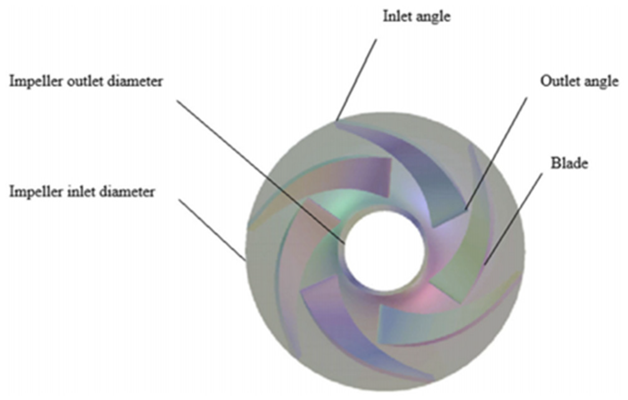
Figure 9.
Geometric parameters of the impeller [111].
Figure 9.
Geometric parameters of the impeller [111].

Figure 10.
Calculation domain of the original model [111].
Figure 10.
Calculation domain of the original model [111].

Figure 11.
Pareto front [111].
Figure 11.
Pareto front [111].


Table 1.
Response surface test design and results [110].
Table 1.
Response surface test design and results [110].
| No. | Blade Outlet Angle/° | Blade Inlet Angle/° | Blade Thickness/mm | Efficiency/% |
|---|---|---|---|---|
| 1 | 22 | 18 | 3.5 | 84.3 |
| 2 | 28 | 18 | 3.5 | 84.2 |
| 3 | 25 | 22 | 3.5 | 86.8 |
| 4 | 28 | 26 | 3.5 | 85.8 |
| 5 | 25 | 22 | 3.5 | 86.3 |
| 6 | 28 | 22 | 2.8 | 86.6 |
| 7 | 25 | 18 | 4.2 | 83.5 |
| 8 | 28 | 22 | 4.2 | 84.7 |
| 9 | 25 | 22 | 3.5 | 86.8 |
| 10 | 25 | 26 | 2.8 | 86.3 |
| 11 | 22 | 26 | 3.5 | 86.1 |
| 12 | 25 | 26 | 4.2 | 85.4 |
| 13 | 25 | 22 | 3.5 | 86.3 |
| 14 | 22 | 22 | 4.2 | 85.5 |
| 15 | 25 | 18 | 2.8 | 84.6 |
| 16 | 25 | 22 | 3.5 | 86.3 |
| 17 | 22 | 22 | 2.8 | 86.2 |
Disclaimer/Publisher’s Note: The statements, opinions and data contained in all publications are solely those of the individual author(s) and contributor(s) and not of MDPI and/or the editor(s). MDPI and/or the editor(s) disclaim responsibility for any injury to people or property resulting from any ideas, methods, instructions or products referred to in the content. |
© 2023 by the authors. Licensee MDPI, Basel, Switzerland. This article is an open access article distributed under the terms and conditions of the Creative Commons Attribution (CC BY) license (https://creativecommons.org/licenses/by/4.0/).
Share and Cite
MDPI and ACS Style
Ji, Y.; Song, H.; Xue, Z.; Li, Z.; Tong, M.; Li, H. A Review of the Efficiency Improvement of Hydraulic Turbines in Energy Recovery. Processes 2023, 11, 1815. https://doi.org/10.3390/pr11061815
AMA Style
Ji Y, Song H, Xue Z, Li Z, Tong M, Li H. A Review of the Efficiency Improvement of Hydraulic Turbines in Energy Recovery. Processes. 2023; 11(6):1815. https://doi.org/10.3390/pr11061815
Chicago/Turabian StyleJi, Yunguang, Hao Song, Zhanpu Xue, Ze Li, Mingda Tong, and Hongtao Li. 2023. "A Review of the Efficiency Improvement of Hydraulic Turbines in Energy Recovery" Processes 11, no. 6: 1815. https://doi.org/10.3390/pr11061815
Note that from the first issue of 2016, this journal uses article numbers instead of page numbers. See further details here.