Article

Constructing a Z-scheme Heterojunction of Egg-Like Core@shell CdS@TiO2 Photocatalyst via a Facile Reflux Method for Enhanced Photocatalytic Performance

1
Key Laboratory for Green Processing of Chemical Engineering of Xinjiang Bingtuan, School of Chemistry and Chemical Engineering, Shihezi University, Shihezi 832003, China
2
School of Environmental and Chemical Engineering, Xi’an Polytechnic University, Xi’an 710048, China
*
Author to whom correspondence should be addressed.
Nanomaterials 2019, 9(2), 222; https://doi.org/10.3390/nano9020222
Submission received: 11 January 2019 / Revised: 31 January 2019 / Accepted: 4 February 2019 / Published: 7 February 2019

Abstract

:
A well designed and accurate method of control of different shell thickness and electronic transmission in a Z-scheme core@shell system is conducive to obtaining an optimum photocatalytic performance. Herein, the Z-scheme heterojunction of egg-like core@shell CdS@TiO2photocatalysts with controlled shell thickness (13 nm, 15 nm, 17 nm, 22 nm) were synthesized by a facile reflux method, and the CdS@TiO2 structure was proved by a series of characterizations. The photodegradation ratio on methylene blue and tetracycline hydrochloride over the 0.10CdS@TiO2 composites with TiO2 shell thickness of 17 nm reached 90% in 250 min and 91% in 5 min, respectively, which was almost 9.8 times and 2.6 times than that of TiO2 and CdS on rhodamine B respectively under visible light. Besides, the higher total organic carbon removal ratio indicated that most of the pollutants were degraded to CO2 and H2O. The Z-scheme electronic transfer pathway was studied through radical species trapping experiments and electron spin resonance spectroscopy. Moreover, the relationship between shell thickness and photocatalytic activity demonstrated that different shell thickness affects the separation of the electron and holes, and therefore affected the photocatalytic performance. In addition, the effects of pollutants concentration, pH, and inorganic anions on photocatalytic performance were also investigated. This work can provide a novel idea for a well designed Z-scheme heterojunction of core@shell photocatalysts, and the study of photocatalytic performance under different factors has guiding significance for the treatment of actual wastewater.

Graphical Abstract

1. Introduction

Semiconductor photocatalysis, as a green technology, is considered to be a potential and viable technique for environmental pollution control [1,2], plasmonics [3], membrane technology [4], and surface science [5]. Ever since Fujishima and Honda reported the utilization of titanium dioxide (TiO2) electrodes and photoelectrocatalyic water splitting to produce hydrogen [6], TiO2 has shown the advantages of physicochemical stability, strong oxidizing ability, non-toxicity and low price, and has therefore played an important role in photocatalytic materials in recent years [7]. However, TiO2 shows limited photocatalytic properties in practical applications due to the high band gap value (3.2 eV), with low absorption characteristics under visible light [8]. Up to now, among the various visible light-active photocatalysts, cadmium sulfide (CdS) has a band gap value (2.4 eV) and high activity and is therefore considered as a favorable candidate for photocatalyst, but photocorrosion effects seriously limit the photocatalytic performance [9]. How to overcome these drawbacks and achieve high-efficiency photocatalysis in practical applications still remains an arduous challenge.
To date, much effort has been devoted to remedy these shortcomings, for instance through metals doping [10], non-metals doping [11], co-doping of metals and non-metals [12], incorporation of grapheme [13], etc. Improving the photo-generated charges separation and photocorrosionby developing a heterostructure between the two semiconductors by core-shell structure is an outstanding strategy. For example, Wang et al. synthesized a core-shell heterojunction TiO2@g-C3N4 composite photocatalyst, indicating that the phenol degradation rate of the composite catalyst was twice as high as that of a single catalyst [14]. Ma et al. successfully prepared CdS@ZnO composite photocatalyst with core-shell structure by atomic layer deposition, which not only solves the problem of CdS photocorrosion but also improves the photocatalytic performance [15]. Tian et al. prepared a core@shell CdS@Cr2O3 catalyst with excellent photocatalytic ability via photodeposition for photocatalytic hydrogen production [16]. Han et al. prepared CdS@TiO2 core@shell materials through a two-step hydrothermal method to improve the photoelectrocatalytic performance, resulting in a high electron transfer quantum efficiency of 79% [17].
Although the composite of the CdS@TiO2core@shell has been reported, the existing synthesis method is energy-intensive and the type II heterojunction electron transport is inefficient [18], and how the thickness of the shell affects the photocatalytic performance is not clear. The type II heterojunction can promote the separation of photo-generated charge carriers, but the reduction and oxidation potential of the composite also decreased, leading to poor photocatalytic performance [19]. Therefore, a facile way to control the synthesis of different shell thicknesses of CdS@TiO2 with high photocatalytic properties would be indispensable. In addition, it is innovative and interesting to conduct an in-depth study on the relationship between shell thickness and photocatalyst performance as well as Z-scheme heterojunction with promoting photo-generated electron-holes separation and maintain their pristine redox capacities [20], which can provide a theoretical basis for improving the performance of photocatalysts.
Herein, we report a flexible synthesis process to construct a Z-scheme of an egg-like CdS@TiO2 core-shell structure via a facile reflux method. In addition, the performance of the photocatalyst was evaluated by degradation of the representative pollutants of methylene blue (MB), rhodamine B (RhB), and tetracycline hydrochloride (TCH). At the same time, in order to better use photocatalytic technology to degradation pollutants, the influence of different factors on photocatalytic performance was studied. Remarkably, the influence of the relationship between shell thickness and photocatalyst performance has been systematically examined. The photocatalysts were characterized by X-ray diffraction (XRD), X-ray photoelectron spectroscopy (XPS), transmission electron microscopy (TEM), fourier transform infrared (FTIR), and photoelectrochemical performance. The photodegradation activity was investigated under visible light, and the proposed mechanism to enhance photocatalytic activity was discussed in detail, while the relationship between shell thickness and photocatalyst performance was also investigated. In addition, the present work may serve as a promising candidate for improving photocatalytic performance.

2. Materials and Methods

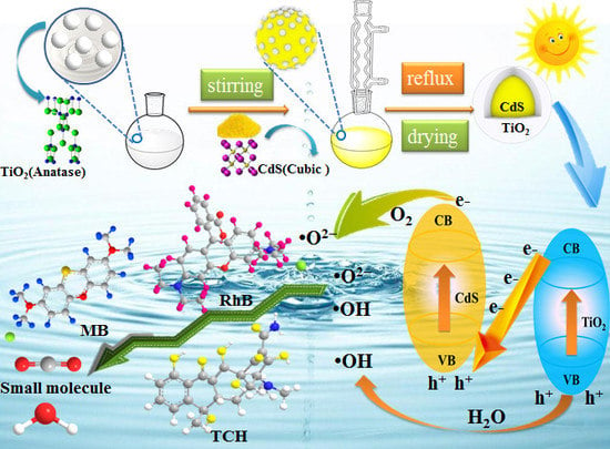
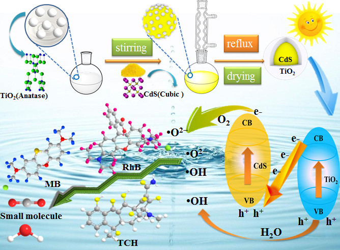
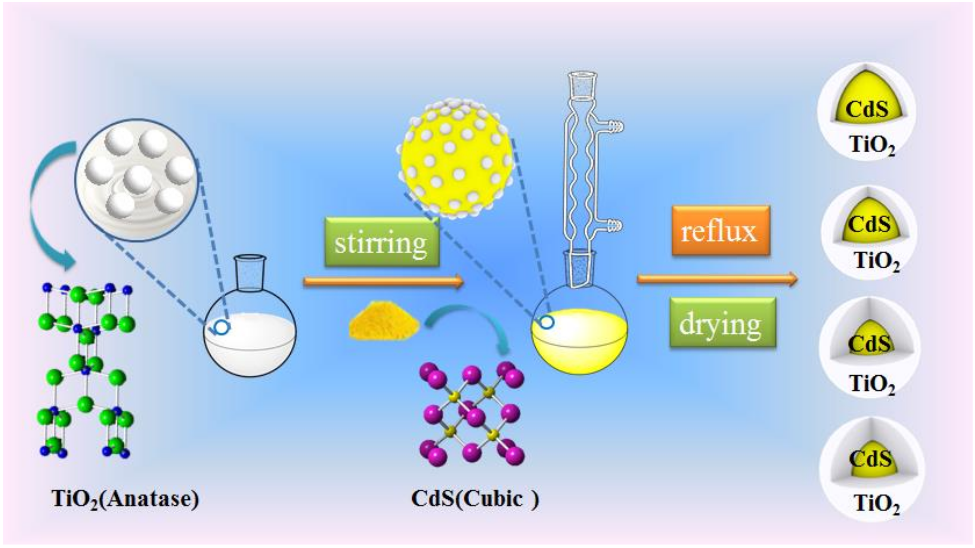
Preparation of Core-Shell Structure CdS@TiO2Composites

The TiO2 was prepared by a conventional sol-gel method. In a typical synthesis, 30 mL of TBOT was added dropwise to EtOH in a volume ratio of 1:1, stirred for 40 min and named Solution A. Meanwhile, solution B was obtained by mixing 14 mL of glacial acetic acid and 7 mL of distilled water in 35 mL of absolute alcohol. Solution B was added dropwise to solution A and stirred at room temperature for 1 h to get light yellow clear TiO2sol. The obtained gel was sealed and stood for 24 h and then dried in an oven at 100 °C for 24 h. The samples were calcined in a muffle furnace under 500 °C for 3 h at a heating rate of 15 °C/min. Finally, the samples were grounded into powder with an agate mortar and collected through a 180 mesh screen.
CdS sample was obtained through a precipitation method. In brief, 50 mL of Na2S (0.14 M) and 50 mL Cd(CH3COO)2 (0.14 M) solution were prepared by ultrasonication for 30 min and stirring vigorously for 30 min to completely dissolve, respectively. Then the Na2S solution was slowly dropwised added into Cd(CH3COO)2 solution accompanied by vigorous stirring. After stirring for 3 hours, the mixture was kept for an additional 24 h. The filtered yellow precipitates were washed by deionized water several times and dried at 80 °C overnight. Finally, the samples were collected and grinded into a powder with an agate mortar.
A facile reflux method was used to construct a core-shell CdS@TiO2 photocatalysts and the preparation process is illustrated in Scheme 1. Firstly, the different mass TiO2 nanomaterials (0.01, 0.05, 0.10, 0.15) were added into 100 mL methanol in a 250 mL round-bottom flask, then through ultrasonication for 30 min to disperse the nanomaterials completely. Then 1 g CdS was added into the above solution, continue stirring for 30 min. Afterwards, the solution was magnetically stirred and refluxed at 68 °C for 12 h. The composite materials were dried at 80 °C for 4 h after evaporation of the methanol. As a result, the different mass ratios of CdS@TiO2 photocatalysts were obtained and named as 0.01CdS@TiO2, 0.05CdS@TiO2, 0.10CdS@TiO2, 0.15CdS@TiO2, respectively.

3. Results and Discussion

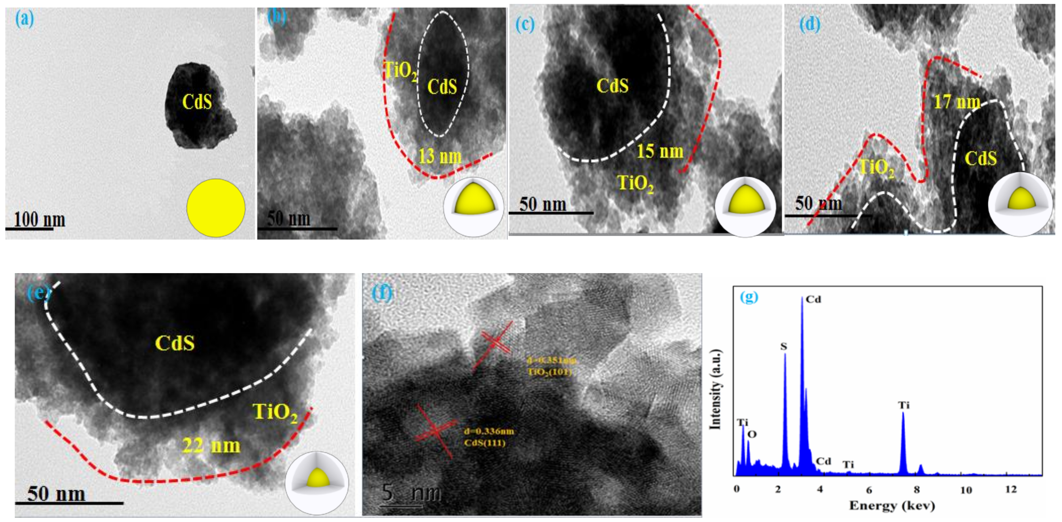
3.1. Fabrication of Core-Shell Structure

The XRD patterns of CdS, TiO2 and CdS@TiO2 composites with different loading qualities of TiO2 were displayed in Figure 1. The pure TiO2 nanoparticles displayed an anatase structure (JCPDS card no. 21-1272) and the peaks located at 25.25, 37.94, and 48.04, corresponding to (101), (004) and (200) planes, respectively. The pure CdS nanoparticle exhibited a cubic structure (JCPDS card no. 10-0454) and the peaks located at 26.5, 43.9 and 52.1 were attributed to the (111), (220) and (311) crystal planes, respectively. It was clear that the crystal structure of CdS in the composite material obviously didn’t change after adding TiO2, indicating that the presence of TiO2 didn’t affect the performance of CdS core. However, the characteristic peaks of pure TiO2 were not discovered in CdS@TiO2 composites, which were due to the low content of TiO2 or the characteristic peaks of pure TiO2, likely overlapped with characteristic peaks of CdS. Ning et al. reported the same phenomenon through modification TiO2 thin film over CdS surface [21]. In addition, from the inset of Figure 1, it’s clear that the characteristic peak of CdS at 26.5° gradually became enhanced and has a light shift to a lower angle with the increase of TiO2 content. This phenomenon reveals a strong interaction between CdS and TiO2 in CdS@TiO2 composites, indicating that TiO2 has been successfully attached to the surface of CdS. Wang et al. had attained a similar phenomenon and conclusion using prepared g-C3N4@ZnO composites as photoanodes for enhanced visible-light photoelectrocatalytic activities [22].
The surface groups and chemical bonds of the photocatalysts were analyzed by FTIR spectra, and the results were shown in Figure S1. The peaks at 3425 cm−1 and 1625 cm−1 are attributed to O-H, and H-O-H, respectively [23]. Moreover, when the TiO2 was added, CdS@TiO2 composites displayed more obvious peaks in the low-wavelength region (Figure S1 rectangular region), and the peak intensity tended to be decrease accompanied by the increases of TiO2 content, which was due to new bonds of CdS@TiO2 at the interface. This led to a decline of the ordered arrangement of CdS and the conjugation network structure was also slightly reduced [14]. Moreover, the new characteristic peaks were observed of 1565 cm−1 and 1245 cm−1 at CdS@TiO2 composite materials, indicating that there are new covalent bonds between CdS and TiO2 rather than a physical mixing. The aforementioned results suggested that TiO2 and CdS may form a heterostructure, and the strong interaction may promote the transfer of electrons and increase the stability of the composite material. Wang et al. reported the same results and demonstrated that the presence of heterojunctions can significantly improve photocatalytic efficiency during the degrading phenol process [14].
To further demonstrate that TiO2 was successfully distributed on the surface of CdS, XPS analysis were characterized. The XPS survey spectrum of 0.10CdS@TiO2 (Figure S2a) proved the existence of Cd, S, Ti, and O elements as C1s (284.8 eV) as the reference. The high-resolution XPS spectra of Cd 3d, S 2p, Ti 2p were illustrated in Figure S2b,S2c,S2d, respectively. The characteristic peaks at 404.8 and 411.5 eV were corresponded to the binding energy of Cd2+ 3d5/2 and 3d3/2 in CdS, respectively. Meanwhile, the peaks at 161.2 and 162.2 eV were indexed to the binding energy of S2− 2p3/2 and 2p1/2 in CdS, respectively. In addition, the peaks located at 458.5 eV and 464.0 eV as Ti 2p3/2 and Ti 2p1/2 respectively, which were typically peaks of Ti4+ [24]. Compared with the binding energy of Cd 3d, S 2p and Ti 2p in pure CdS, TiO2 and 0.10CdS@TiO2, it is obvious that there is a significant shift in the characteristic peak of 0.10CdS@TiO2. The strong interaction between CdS and TiO2 may lead to a shift in binding energy. All of these results illustrated the successful preparation of CdS@TiO2 core-shell nanocomposites, and the nanocomposites were very stable due to their interaction between CdS and TiO2, which is consistent with the results reported by Ning et al. [21].
The formation of core-shell structure was more directly demonstrated in TEM, and the thickness of the shell is also estimated. It can be seen from Figure 2a that the CdS has a relatively uniform morphology. The TEM images of 0.01, 0.05, 0.10 and 0.15CdS@TiO2 composites were shown in Figure 2b–e, respectively. It can be observed that TiO2 is evenly distributed on the surface of CdS, which is in sharp contrast with the pure CdS, and which further demonstrated that a core-shell structure was formed between CdS and TiO2. From HRTEM images in Figure 2f, the inter planar spacings were estimated to be 0.351 nm and 0.336 nm and corresponded to the (101) plane of TiO2 and (111) plane of CdS, respectively. This indicated that there was no change in the lattice structure of CdS after loading TiO2and that a strong heterostructure was formed between CdS and TiO2. In Figure 2g, the EDX data could also prove the existence of Cd, S, Ti and O in CdS@TiO2 nanocomposite, implying that the CdS@TiO2 photocatalyst was successfully composited. In addition, with the increase of the initial content of TiO2 (0.01, 0.05, 0.10, 0.15 g), the thickness of the TiO2 shell in the composite material also increased (13, 15, 17, 22 nm), so it is possible to accurately control the thickness of the shell by changing the initial amount of TiO2. The direct contact or good interfaces between TiO2 shell and CdS contributed to the effective separation of photo-generated electrons and holes. Besides, different shell thicknesses had a significant effect on the separation efficiency, so it is possible that the optimal shell thickness can be found by changing the initial amount of TiO2 to improve the photocatalytic efficiency. Wang et al. also found that the optimal g-C3N4 shell thickness can effectively improve photoelectrocatalytic ability during the preparation of g-C3N4@ZnO core-shell nanomaterials [25]. Therefore, it is worthwhile to do further study to show that the core-shell photocatalysts with different shell thickness is a way to improve the performance.

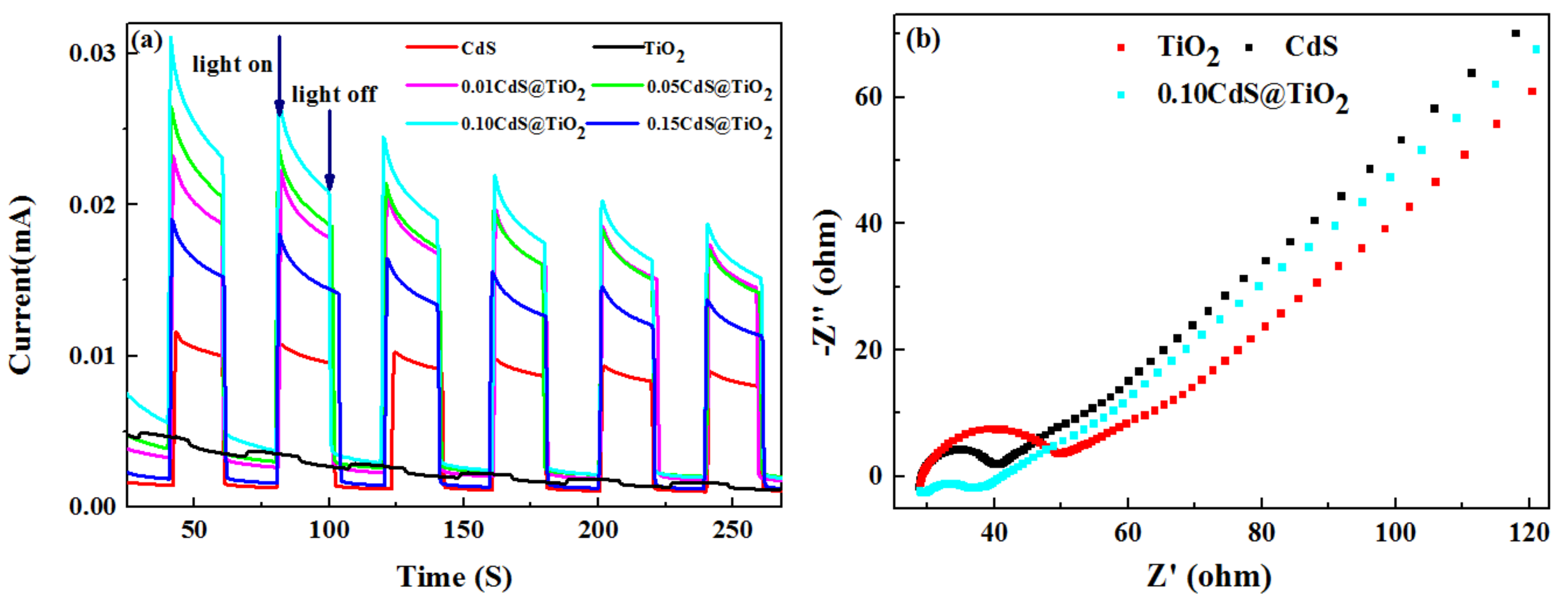
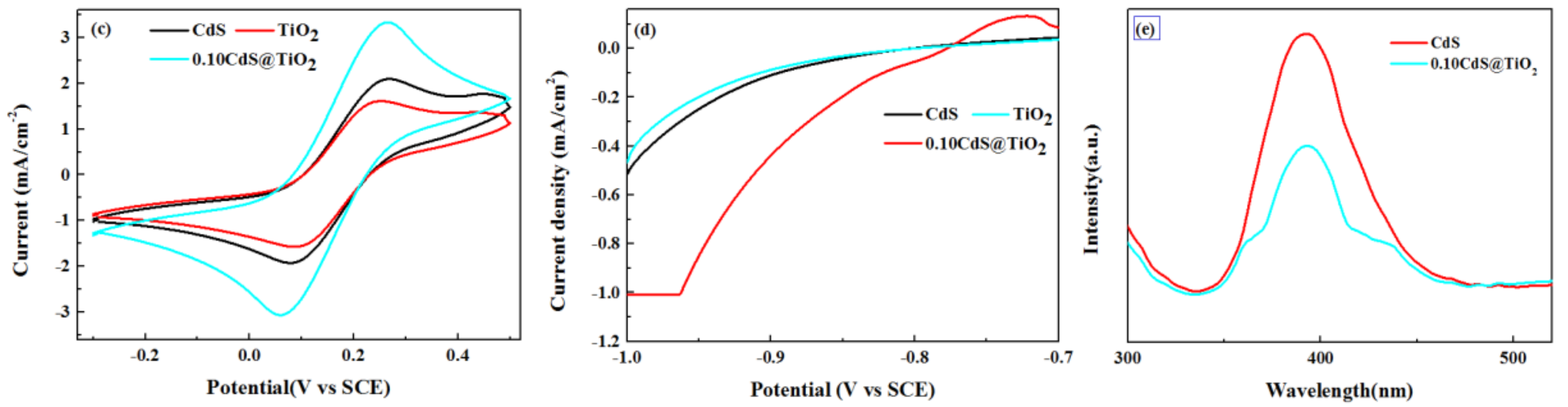
3.2. Photoelectrochemical Propertiesof Core-Shell Structure CdS@TiO2Photocatalyst

The UV–visible absorption spectra of CdS, TiO2 and CdS@TiO2 with different mass ratios of TiO2 were shown in Figure S3. The band gap (Eg) of the sample was calculated from the absorption edge initial value using the formula Δg = 1239/Eg, where Δg is the bandgap wavelength [25]. As expected, pure TiO2 had a basic absorption edge at 410 nm, and the band gap is about 3.13 eV, suggesting higher photocatalytic activity under UV irradiation, but the absorption edge and band gap of CdS were corresponding to 600 nm and 2.25 eV, respectively. It is notable that the UV–visible absorption spectra of CdS@TiO2 presented a similar characteristic with CdS rather than TiO2, mainly because of the low content of TiO2, which demonstrated that CdS@TiO2 heterostructure had been successfully constructed. Furthermore, the CdS@TiO2possesses a strong visible-light absorption band and shows an evident blue shift accompanied by an increasing loading amount of TiO2, which suggests that suitable TiO2 content in CdS@TiO2 composites is beneficial [26] and consistent with the TEM results. Therefore, a reasonably designed TiO2 shell thickness is crucial for high performance photocatalytic materials.
The photocurrent response of CdS, TiO2 and CdS@TiO2 composites have been measured to evaluate the efficiency of charge carriers transfer and separation (Figure 3). A higher photocurrent density usually means a higher separation ability of photo-generated electrons and holes [27]. The photocurrent response of TiO2 has almost no difference in light on and light off conditions, mainly due to TiO2 absorb less visible light, which is in accordance with the conclusion of UV–visible absorption spectra. The CdS possesses a low photocurrent density under visible light for the rapid recombination of photo-generated electrons and holes. However, after adding TiO2, CdS@TiO2 composites displayed a significant increase of photocurrent density compared with CdS, indicating that the covalent bond at core-shell structure heterojunction can effectively promote the separation of photo-generated electrons and holes [28]. The 0.10CdS@TiO2 composites showed the strongest photocurrent response (0.0260 mA), as high as 2.48 times and 8.39 times higher than that of CdS (0.0105 mA) and TiO2 (0.0031 mA), respectively, may increase the photocatalytic efficiency. It is well known that EIS was used to evaluate electron transfer efficiency and the result was shown in Figure 3b. In general, a smaller EIS arc radius indicated a higher charge mobility [22]. It can be observed that the radius of TiO2 and CdS were much larger than that of 0.10CdS@TiO2 composites, demonstrating that the formation of heterojunction was important in facilitating the transfer and separation of photo-generated electrons and holes. As shown in Figure 3c, the CV curves of 0.10 CdS@TiO2 had a strong anodic peak compared with CdS and TiO2, indicating that more photo-generated holes existed [27], which may indicate that the 0.10CdS@TiO2 has high photo-generated electron and hole separation efficiency. The polarization curves of CdS, TiO2 and 0.10CdS@TiO2 were displayed in Figure 3d, where it was easy to see that the current of the sample increased the forward bias voltage, indicating that the photocatalyst were typical n-type semiconductors. The 0.10CdS@TiO2 sample showed an enhanced current compared with pure CdS and TiO2, indicating that 0.10CdS@TiO2 was an excellent photocatalyst and the photocatalytic performance was significantly improved [21]. In addition, PL was another valid electrochemical strategy to assess the electron-transfer efficiency. The PL spectra (Figure 3e) of CdS exhibited a strong peak at around 400 nm, which suggested a high recombination rate of the photo-generated electrons and holes of CdS [29]. Fortunately, the peaks of the 0.10CdS@TiO2photocatalyst decreased remarkably, indicating that the presence of TiO2 shell can effectively prevent the recombination of CdS photo-generated electrons and holes. Based on the above results and characterization analysis, the presence of TiO2 and CdS core-shell heterojunction can effectively promote the separation of photo-generated electrons and holes and increase photocatalytic efficiency.

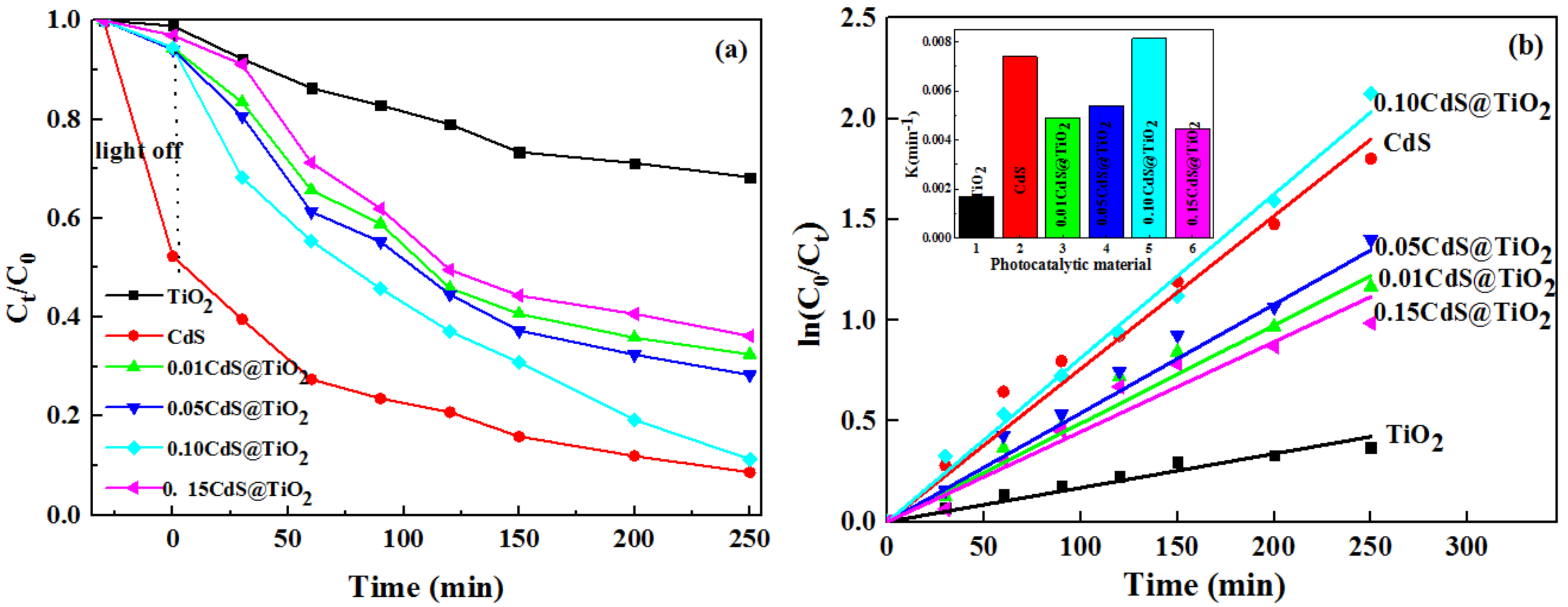
3.3. Photocatalystic Activity of Core-Shell Structure CdS@TiO2 Photocatalyst

To assess the photocatalytic properties of the prepared samples, degradation of typical dye MB was performed, and the results were displayed in Figure 4a,b. It can be found that the concentration of MB exhibited minor changes with the addition of TiO2 under visible light, because TiO2 doesn’t absorb visible light effectively. The 0.10CdS@TiO2 exhibited highest photocatalytic activity and the photodegradation ratio reached 90% in 250 min, mainly due to effective separation rates of photo-generated electrons and holes. Interestingly, CdS had a higher adsorption capacity in the dark reaction stage, but the capacity of adsorption dropped dramatically after the addition of TiO2. Figure S4a illustrated that the peaks of CdS in the 3500 and 1600 cm−1 region fluctuated significantly and the peak at 620 cm−1 disappeared after adsorption. Figure S4b showed that the characteristic peak position of CdS didn’t change, while the intensity became smaller after adsorption. From FTIR and XRD analysis, it can be inferred that CdS and MB can be combined with chemical bonds, so the concentration of MB was decreased significantly in the dark reaction stage. Meanwhile, the CdS@TiO2 adsorption capacity can be ignored compared with CdS, it is mainly due to the strong interaction of CdS@TiO2, and the TiO2 shell can successfully overspread the CdS core, which can further confirm the formation of core-shell CdS@TiO2 structure.
Considering the interaction between CdS and MB, RhB is also a cationic dye and degraded to further assess the photocatalytic properties of the samples. From Figure 4c, the adsorption experiments indicated the adsorption capacity of the samples was negligible. Meanwhile, the CdS and TiO2 displayed low photocatalytic activities. Furthermore, it’s clear that the as-prepared CdS@TiO2 composites obviously enhanced the photocatalytic degradation activity of RhB. While the amount of TiO2 was 0.10, the prepared photocatalyst exhibited the best photocatalytic activity, and the degradation rate is 2.6 times and 9.8 times greater than pure CdS and TiO2, respectively, which is consistent with the photocurrent results. Since most dyes can be degraded by their own photo-sensing mechanism, we further selected colorless TCH as a typical pollutant to evaluate the photocatalytic performance in order to eliminate the influence of dye sensitization. As shown in Figure 4e, the adsorption experiments indicated the adsorption capacity of the CdS@TiO2 was significantly increased relative to CdS and TiO2, which is probably due to the increased surface area of the composite. The 0.10CdS@TiO2 showed superior photocatalytic performance, and TCH can be degraded 92% in 5 min, while only 19%, 62% of TCH can be decomposed in the case of TiO2, CdS, respectively. The CdS@TiO2 composites possessed superior photocatalytic properties to CdS due to the interaction of core-shell heterogeneous structures. Although TiO2 was beneficial to the charge transfer, superabundant TiO2 would act as the recombination centers of electron-hole pairs and blocked visible light absorption, leading to a less photocatalytic activity [30]. Therefore, the appropriate TiO2 content is important for enhancing the photocatalytic performance of the core-shell photocatalyst.
Total organic carbon analyzer (TOC) was employed to evaluate the mineralization of pollutants, and then to further evaluate the photocatalytic performance. Figure S5 showed the results for the photodegradation and mineralization of MB, RhB and TCH. It is easy to find that the photodegradation efficiency is higher than the mineralization efficiency, indicating the presence of intermediates in the photocatalytic reaction. In addition, MB and RhB have relatively high mineralization ratios, indicating that most of them are decomposed into CO2 and H2O during the process of photocatalytic degradation. However, although TCH has a higher degradation ratio, the mineralization ratio is lower, mainly because a large amount of intermediate products are produced in a short time, and only a small amount is converted into CO2 and H2O. Therefore, in the actual photocatalytic degradation, in order to completely convert the pollutants into small molecules of CO2 and H2O, the time can be extended appropriately.

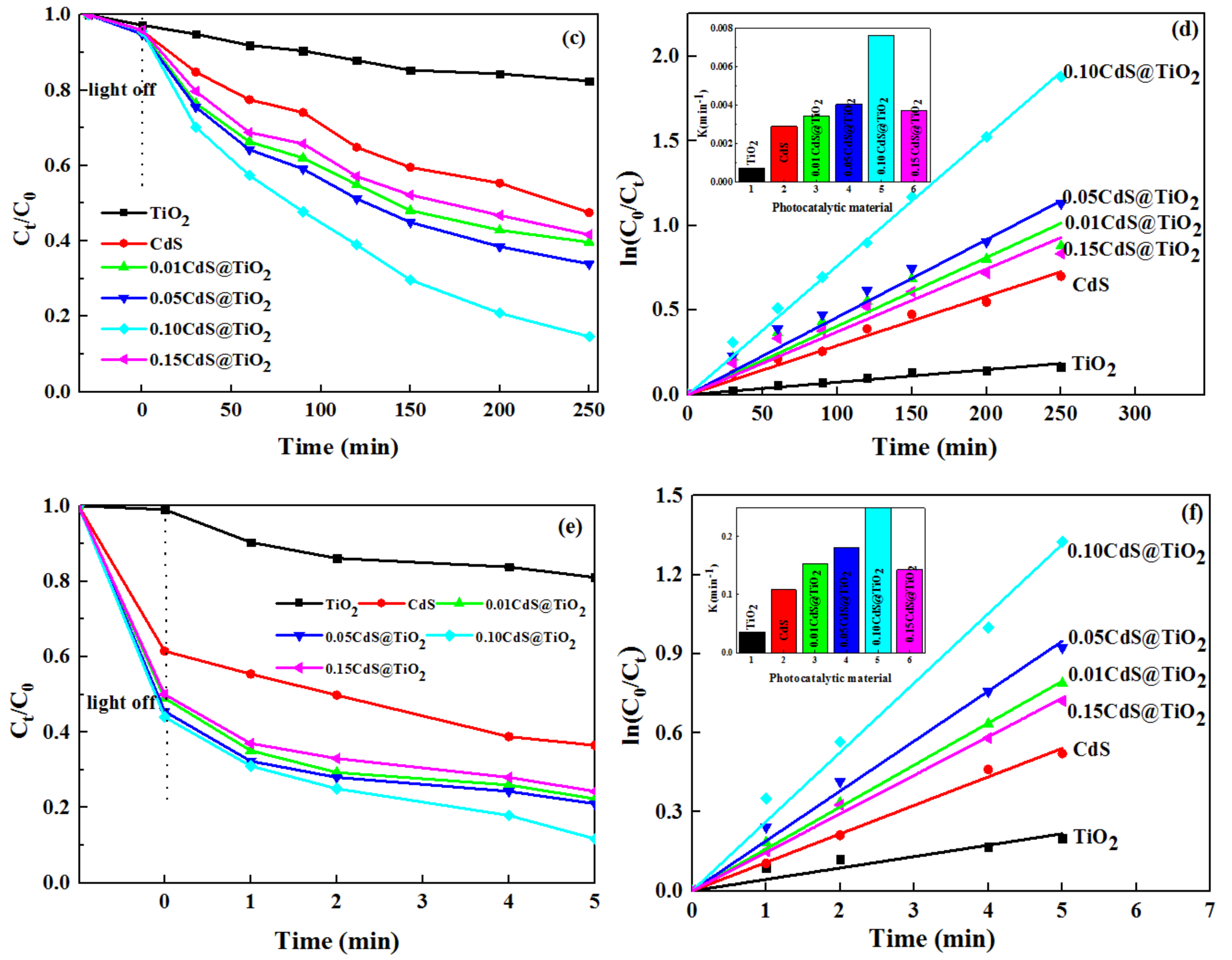
3.4. Effects of Different Factors on Photodegradation

The degradation efficiencies of 0.10CdS@TiO2 for MB, RhB, and TCH at different initial pH values were shown in Figure 5a. It is easy to find that the degradation ratio of RhB and MB decreases with the increase of initial solution pH, which indicates that acid environment exhibits positive influence on photocatalytic process. This phenomenon was related to the charge on the surface of the composite and the electronegativity of the different initial pH solution [31], so the Zeta potential of the 0.10CdS@TiO2 composite was tested at different solution pH values and the results were displayed in Table 1. The results showed that the composite has a negative surface charge between pH 3–11, and the charge decreases as the pH increases. While the surface of RhB and MB is positively charged, the adsorption capacity decreases with the increase of initial solution pH, and then the degradation ration decreases. However, the degradation ratio of TCH increases with the increase of initial pH, which is mainly attributed to the TCH being destroyed easily under alkaline conditions [32]. Therefore, in the actual wastewater treated with 0.10CdS@TiO2, the initial pH of RhB and MB should be acidic, and the initial pH of TCH should be alkaline, which can achieve a higher degradation ratio.
In the practical wastewater, the concentration of pollutants may vary greatly and have a serious impact on photocatalytic activity, so it is important to research the influence of different pollutant concentrations on photocatalytic activity. As depicted in Figure 5b, a series of concentrations (10–50 mg/L MB, 10–50 mg/L RhB, 20–60 mg/L TCH) were chosen to study the relationship between contaminant concentration and photocatalytic performance. The results showed that the degradation ratio decreases with the increase of MB, RhB and TCH initial concentrations. This phenomenon is mainly attributed to the higher concentration causing the active site on the surface of CdS@TiO2 to be occupied, and the intermediate product also participates in the competition of the active site as the degradation progresses [33]. Therefore, for the sake of obtaining a better photodegradation ratio, a dilution process is needed to reduce the concentration of high pollutants in practical applications. 10 mg/L MB, RhB and 20 mg/L TCH were chosen as the best initial concentration in the whole experiment.
As is well known, since surface water and real wastewater usually contain more inorganic anions (Cl, SO42−, CO32−), it is urgent to systematically evaluate the effect of their presence on the photodegradation of contaminant. Figure 5c showed the effect of 0.1 M inorganic salts (NaCl, Na2SO4 and Na2CO3) on Photocatalytic performance. It observed that NaCl have positive effect on MB, RhB and TCH removal during the photocatalytic process, which might be ascribed to the addition of ions (Na+, Cl) in the solution that promote the migration of photogenerated electrons to some extent and inhibits the recombination of electrons and holes, and thus improves the degradation ratio [34]. In addition, Na2SO4 had a slight inhibitory effect on photocatalytic degradation, which may be due to the fact that the addition of Na2SO4 does not change the reaction system but occupies the photocatalytic active site [35]. However, Na2CO3 has a significant inhibitory effect on photocatalytic degradation, mainly because CO32− is an effective scavenger for h+ and which can consume a large amount of h+, thereby reducing photocatalytic performance. Therefore, in the actual wastewater treatment, NaCl can be appropriately added to improve the photocatalytic efficiency and reduce the content of Na2SO4 and Na2CO3 in the wastewater.

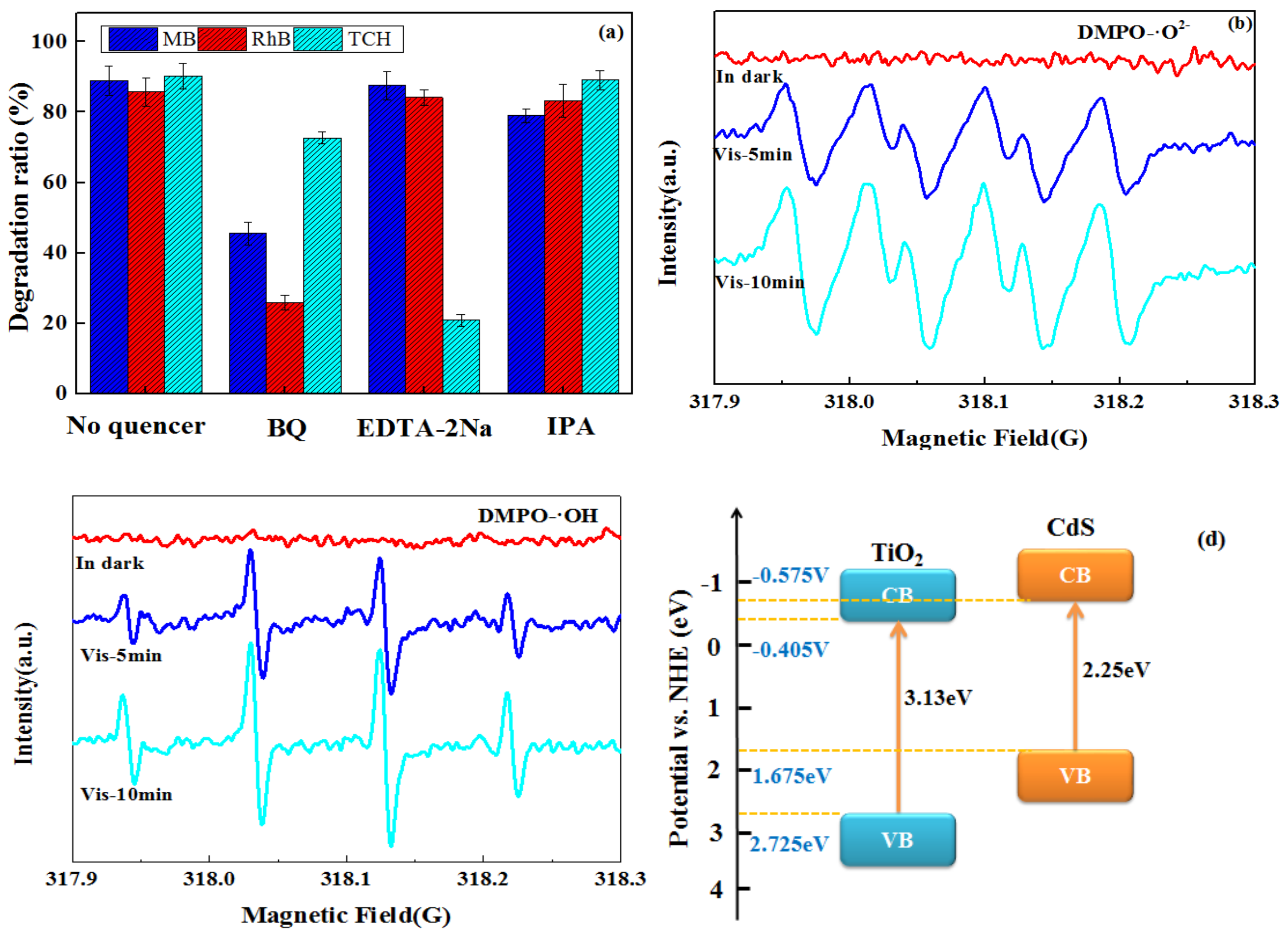
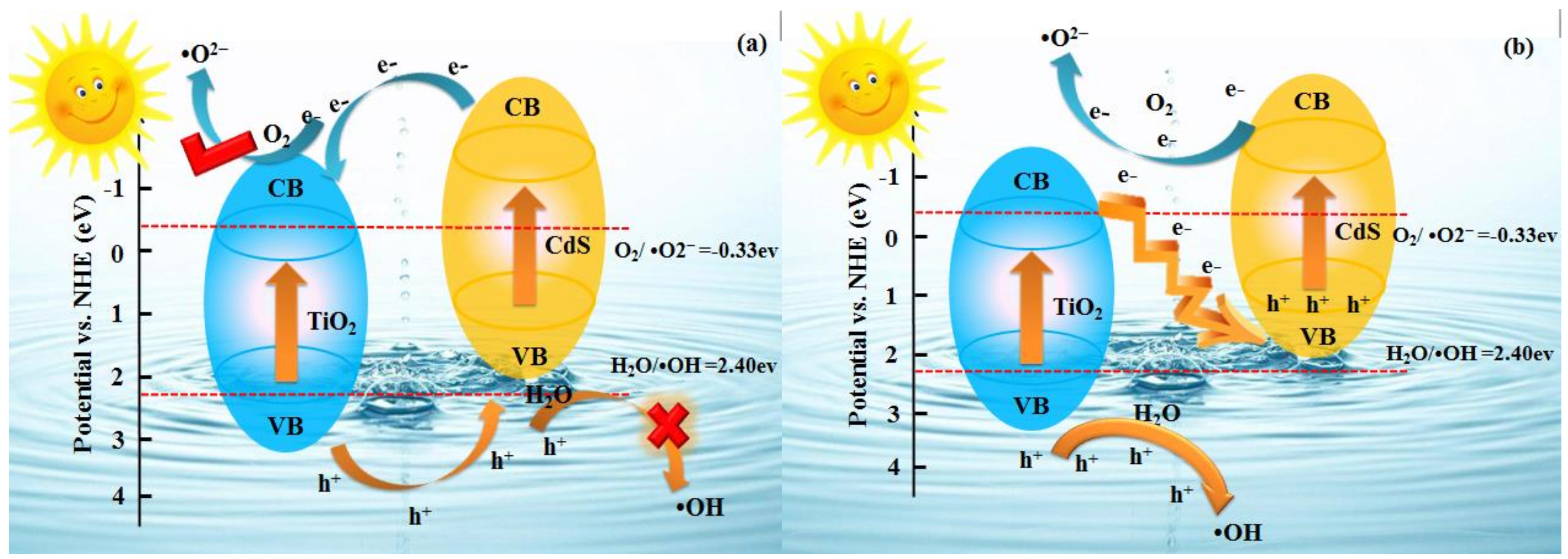
3.5. Mechanism of Pollutant Photodegradation

To explore the mechanism of the photocatalytic reaction, the active species trapping experiments for the MB, RhB and TCH degradation over 0.10CdS@TiO2were carried out. Figure 6a displayed the photocatalytic process of 0.10CdS@TiO2 with different quenchers. The p-benzoquinone (BQ), isopropanol (IPA) and EDTA-2Na were employed as the quenchers for •O2, •OH and h+, respectively. In the degradation of MB, the degradation ratio rapidly decreased after adding BQ, and the degradation ratio decreased slightly after adding IPA, while it shows negligible effect after adding EDTA-2Na. It is indicated that •O2 and •OH were the main active species in the photodegradation MB processes. In the degradation of RhB, the degradation ratio dropped rapidly after adding BQ, while the degradation ratio was basically unchanged after adding IPA and EDTA-2Na, suggesting that •O2 was the main active species in the photodegradation RhB processes. In the degradation of TCH, the degradation ratio decreased rapidly after adding BQ and EDTA-2Na, which indicated that •O2 and h+ are the main active species in the photodegradation TCH processes. ESR analyses were applied to further affirm the presence of •O2 and •OH species during the photocatalytic reaction. As illustrated in Figure 6b,c, neither •O2 and •OH radicals were detected in the dark. After irradiation under visible light, the distinct characteristic peaks of DMPO-•O2 and DMPO-•OH can be observed, suggesting that •O2 and •OH radicals were generated after visible light irradiation. In addition, the characteristic peaks of DMPO-•O2− and DMPO-•OH were increased with time change. The ESR analysis demonstrated that the generation of •O2 and•OHplayed crucial roles in the photodegradation process under visible light irradiation, which was similar to the results of trapping experiments.
Additionally, it was known that the band structure played a vital role in a core-shell heterostructure photocatalyst. The conduction band edge (ECB) and value band edge (EVB) of a semiconductor could be calculated by the following formula [36,37]:
ECB = X− Ee − 0.5Eg
EVB = ECB + Eg
where Ee is the energy of free electrons on the hydrogen scale (≈ 4.5 eV), the value of absolute electronegativity X for CdS is 5.05 [38] and TiO2 is 5.66 [39], Eg is the band gap of the semiconductor. The band gap energies of CdS and TiO2 were obtained to be 2.25 eV and 3.13 eV in the previous UV-vis discussion. Thus, the EVB of CdS and TiO2 could be calculated to be +1.675 eV and +2.725 eV and the corresponding ECB were estimated to be −0.575 eV and −0.405 eV, respectively, which appear in Figure 6d. As a result, the photo-generated electrons and holes could easily transfer between CdS and TiO2 due to the band energy potential difference and interactive energy band structure.
Based on all of the above calculation results, a more reasonable explanation for the improved photocatalytic activity of the CdS@TiO2 composite photocatalyst was presented, and the possible pathways for charge transfer and redox reactions were depicted in Figure 7. Under visible light irradiation, both CdS and TiO2 could easily produce photo-electron and hole pairs because of their narrow band gaps. If the carriers of CdS @ TiO2 composites transferred were in accord with the path in Figure 7a, due to the CdS having a more negative CB potential than TiO2, photogenerated electrons were transferred from the CB of CdS to CB of TiO2. Meanwhile, owing to the TiO2 having a more positive VB potential than CdS, the hole of TiO2 migrates to the VB of CdS. However, if this assumption is reasonable, the h+ accumulated in the VB of CdS could not reduce H2O to •OH (H2O /•OH, 2.40 eV vs. NHE) [40], which is opposite to the results of the radical species trapping experiments and ESR analysis discussed above. Hence, CdS@TiO2 composites are unfavorable for the formation of active species if the photogenerated charge transfer conforms to the traditional type II heterojunction. Therefore, it can be inferred that the photo-generated charge transfer method follows the Z-scheme mechanism without an electron mediator, as shown in Figure 7b. In contrast to a conventional heterojuntion mechanism, the fast combination was reached between the electrons in the CB of TiO2 and the holes in the VB of CdS, so the electrons in the CB of CdS and the holes in the VB of TiO2 can be retained. Then the CdS@TiO2 composites can generate •O2 and •OH, because CdS has a more negative CB potential (O2/•O2, −0.33 eV vs. NHE) [41] and TiO2 has a more positive VB potential (H2O/•OH, 2.40 eV vs. NHE), which is consistent with the results of radical species trapping experiments and ESR analysis. Therefore, it can be confirmed that the proposed mechanism of direct Z-scheme is reasonable for a CdS@TiO2 composite.
Based on all of the aforementioned results, the formation of a direct CdS@TiO2 Z-scheme heterojunction photocatalytic system is very important for the separation of photo-generated electrons and holes. It is clear that the photodegradation of MB, RhB and TCH solution followed a strong oxidation process (Equations (3–10)) [42], which can provide a theoretical basis for the efficient removal of pollutants.
CdS + Visible light → e-(CdS) + h + (CdS)
TiO2 + Visible light → e-(TiO2) + h + (TiO2)
e-(TiO2) + h + (CdS) → Recombination
e(CdS) + O2→ •O2
h+(TiO2) + H2O → •OH
h++ (TCH) → Degradation products (CO2 + H2O)
•O2 + (MB, RhB, TCH) → Degradation products (CO2 + H2O)
•OH + MB → Degradation products (CO2 + H2O)

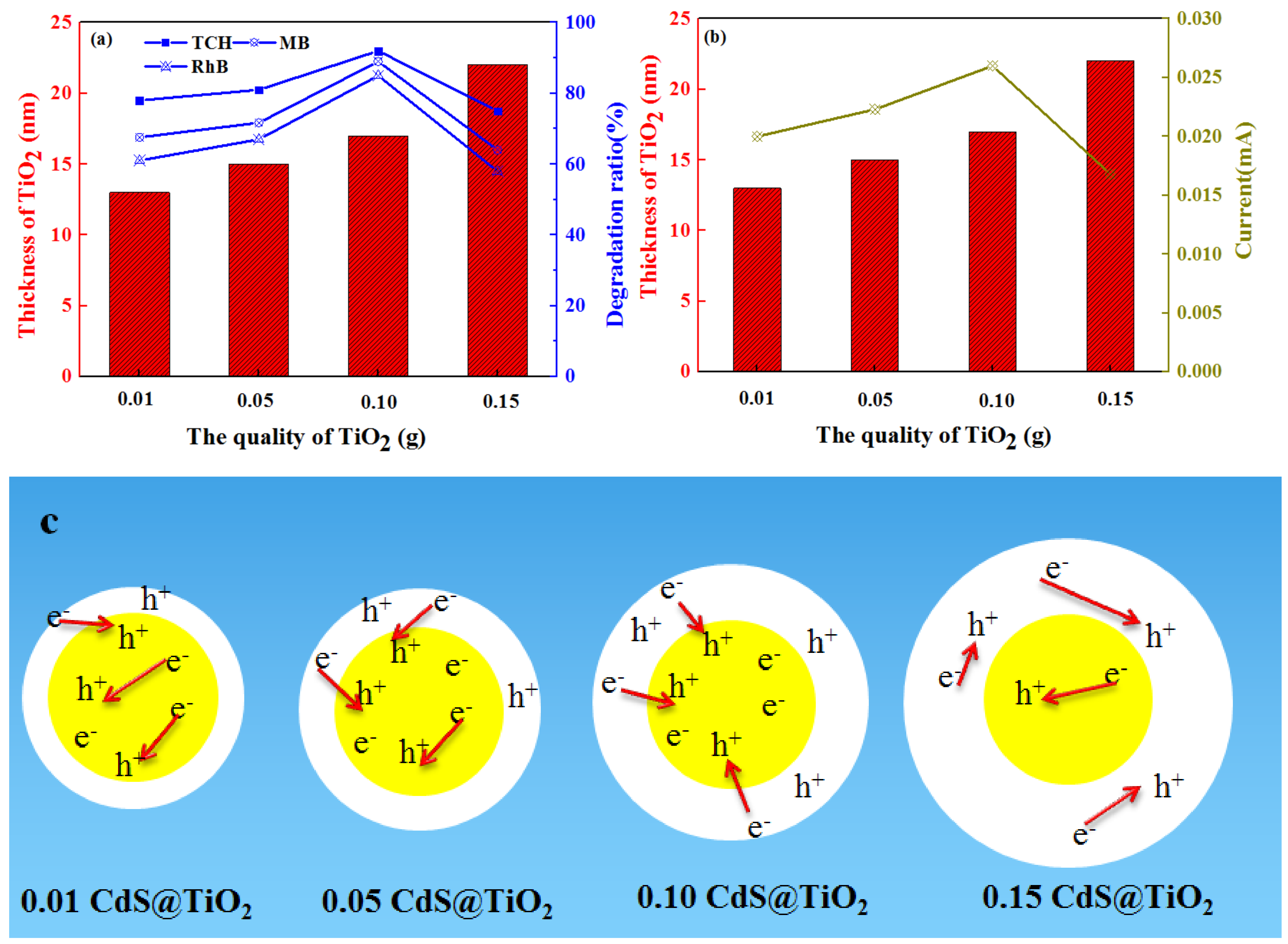
3.6. The Structure-Effective Relationship of Core-Shell Photocatalyst

The previous results have shown that the core-shell composite photocatalyst has a great improvement in photocatalytic performance, so it is important to study how the core-shell structure affects photocatalytic performance. The structure-effective relationship was profoundly revealed, as shown in Figure 8a. With the increase of the TiO2 shell thickness from 13 nm to 17 nm, the degradation ratios of MB, RhB and TCH gradually improve. While further increasing the TiO2 layer, the degradation ratios of MB, RhB and TCH declined. The improvement of photocatalytic performance on the core-shell structure may be due to the separation of photogenerated electrons and holes. Therefore, the relationship between the thickness of the shell and the photocurrent was studied, as shown in Figure 8b. The photocurrent increases first and then decreases as the thickness of the shell increases. It showed the same trend as photocatalytic performance, further demonstrating that the core-shell structure improved the separation of electron holes and then enhanced photocatalytic performance. Furthermore, as shown in Figure 8c, when the content of TiO2 is low, the electrons generated by TiO2 cannot be completely combined with the holes of CdS, and the electrons and holes of CdS still recombine, so the photocatalytic efficiency is lower [43]. When the thickness of TiO2 layer is 22 nm, the degradation ratio was declined. There are two aspects that may apply to explicate the phenomenon, for one, the superabundant TiO2 layer seriously hinders the absorption ability of CdS to visible light [44], for another, an excess of TiO2 in the shell layer becomes the recombination center of electrons and holes, which increases the recombination of electrons and holes [45]. In brief, the shell thickness affects the separation of electron and holes, and then affects photocatalytic performance. This rule can provide the theory basis for the construction of high photocatalytic properties of the core-shell structure photocatalyst.

3.7. Photostability over 0.10CdS@TiO2 under Visible Light

To study the reusability and photostability of the photocatalyst, the photocatalytic degradation of recycled 0.10CdS@TiO2 was tested under visible light irradiation. As shown in Figure S6, the photocatalytic activity of the recycled photocatalyst showed no noticeable change after three recycling runs, which demonstrates that 0.10CdS@TiO2photocatalyst is highly-efficient and stable. This result reveals that the core-shell CdS@TiO2 successfully solved the problem of CdS photocorrosion. It provided a new way to solve the problem of photocorrosion and improve photocatalytic performance.

4. Conclusions

The Z-scheme heterojunctionof egg-like core@shell CdS@TiO2 photocatalysts with controlled TiO2 layer were successfully prepared by facile reflux approaches, which reveal the structure-effective relationship between core-shell structure and photocatalytic activity. The photodegradation ratio on MB and TCH reached 90% in 250 min and 91% in 5 min, respectively, and the photodegradation rate is almost 9.8 times and 2.6 times higher than that of TiO2 and CdS on RhB under visible light. It can be attributed to the Z-scheme heterojunction, which not only promotes the separation of photo-generated electrons and holes but also improves photocatalytic properties. In addition, the core@shell CdS@TiO2 photocatalysts were prepared by the facile reflux method possessed a strong binding force, which can effectively avoid the CdS photocorrosion. This work can provide a new strategy to rationally design Z-scheme heterojunction of photocatalysts, which is important for photocatalysts with efficient charge separation. Moreover, the relationship between shell thickness and photocatalytic activity can provide another reference for the constructed core-shell photocatalysts.

Supplementary Materials

The following are available online at https://www.mdpi.com/2079-4991/9/2/222/s1, Scheme 2: The photoelectrochemical measurement of core-shell CdS@TiO2photocatalytic materials, Figure S1: FTIR spectra of CdS, TiO2 and CdS@TiO2 composites, Figure S2: XPS survey spectrum of sample 0.10CdS@TiO2(a); high-resolution XPS spectra of Cd 3d(b), S 2p (c) in sample 0.10CdS@TiO2 and CdS; high-resolution XPS spectra of Ti 2p (d) in sample 0.10CdS@TiO2 and TiO2, Figyre S3: UV–visible absorption spectra of CdS, TiO2 and CdS@TiO2 samples (a), the plots (ahv)1/2 versus energy (hv) for the band gap energies by using Kubelka-Munk (b), Figure S4: FTIR (a) and XRD patterns (b) of CdS before and after adsorption tests, Figure S5: TOC removal ratio on MB, RhB (250 min) and TCH (5 min) by 0.10CdS@TiO2 composite under visible light irradiation, Figure S6: Repetitive photocatalytic degradation of MB, RhB and TCH over 0.10CdS@TiO2 under visible light.

Author Contributions

The manuscript was completed through contributions of all authors. Y.X. and Z.W. planned the project and designed the experiments. X.H., X.C., Z.G., analyzed the data. X.Y. modified the language and results.

Funding

National Natural Science Foundation of China (21868034), International Science and Technology Cooperation Program of Shihezi University (GJHZ201601).

Acknowledgments

This work was supported financially by funding from the National Natural Science Foundation of China (21868034), International Science and Technology Cooperation Program of Shihezi University (GJHZ201601).

Conflicts of Interest

The authors declare no conflict of interest.

References

  1. Chen, X.; Wu, Z.; Liu, D.; Gao, Z. Preparation of ZnO photocatalyst for the efficient and rapid photocatalytic degradation of azo dyes. Nanoscale Res. Lett. 2016, 12, 143–153. [Google Scholar] [CrossRef] [PubMed]
  2. Chen, X.; Wu, Z.; Gao, Z.; Ye, B.C. Effect of different activated carbon as carrier on the photocatalytic activity of Ag-N-ZnO photocatalyst for methyl orange degradation under visible light irradiation. Nanomaterials 2017, 7, 258. [Google Scholar] [CrossRef] [PubMed]
  3. Kang, Y.; Gong, Y.; Hu, Z.; Li, Z.; Qiu, Z.; Zhu, X.; Fang, Z. Plasmonic hot electron enhanced MoS2 photocatalysis in hydrogen evolution. Nanoscale 2015, 7, 4482–4488. [Google Scholar] [CrossRef]
  4. Politano, A.; Cupolillo, A.; Di Profio, G.; Arafat, H.A.; Chiarello, G.; Curcio, E. When plasmonics meets membrane technology. J. Phys. Condens. Matter 2016, 28, 363003. [Google Scholar] [CrossRef] [PubMed]
  5. Michael, A. A surface science perspective on photocatalysis. Surf. Sci. Rep. 2011, 66, 6–7. [Google Scholar]
  6. Fujishima, A.; Honda, K. Electrochemical photolysis of water at a semiconductor electrode. Nature 1972, 238(5358), 37–38. [Google Scholar] [CrossRef] [PubMed]
  7. Tian, F.; Wu, Z.; Yan, Y.; Ge, X.; Tong, Y. Photodegradation of formaldehyde by activated carbon loading TiO2 synthesized via microwave irradiation. Korean J. Chem. Eng. 2015, 32, 1333–1339. [Google Scholar]
  8. Chen, X.; Liu, D.; Wu, Z.; Cravotto, G.; Wu, Z.; Ye, B.C. Microwave-assisted rapid synthesis of Ag-β-cyclodextrin/TiO2/AC with exposed {001} facets for highly efficient naphthalene degradation under visible light. Catal. Commun. 2018, 104, 96–100. [Google Scholar] [CrossRef]
  9. Dong, W.; Pan, F.; Xu, L.; Zheng, M.; Sow, C.H.; Wu, K.; Xu, G.Q.; Chen, W. Facile synthesis of CdS@TiO2 core–shell nanorods with controllable shell thickness and enhanced photocatalytic activity under visible light irradiation. Appl. Surf. Sci. 2015, 349, 279–286. [Google Scholar] [CrossRef]
  10. Yang, X.; Li, J.; Wen, T.; Ren, X.; Huang, Y.; Wang, X. Adsorption of naphthalene and its derivatives on magnetic graphene composites and the mechanism investigation. Colloids Surf. A 2013, 422, 118–125. [Google Scholar] [CrossRef]
  11. Liu, D.; Wu, Z.; Tian, F.; Ye, B.C.; Tong, Y. Synthesis of N and La co-doped TiO2/AC photocatalyst by microwave irradiation for the photocatalytic degradation of naphthalene. J. Alloy. Compd. 2016, 676, 489–498. [Google Scholar] [CrossRef]
  12. Tian, F.; Wu, Z.; Tong, Y.; Wu, Z.; Cravotto, G. Microwave-assisted synthesis of carbon-based (N, Fe)-codoped TiO2 for the photocatalytic degradation of formaldehyde. Nanoscale Res. Lett. 2015, 10, 360. [Google Scholar] [CrossRef] [PubMed]
  13. Bera, R.; Kundu, S.; Patra, A. 2D hybrid nanostructure of reduced graphene oxide–CdS nanosheet for enhanced photocatalysis. ACS Appl. Mater. Interfaces 2015, 7, 13251–13259. [Google Scholar] [CrossRef] [PubMed]
  14. Wang, Y.; Yang, W.; Chen, X.; Wang, J.; Zhu, Y. Photocatalytic activity enhancement of core-shell structure g-C3N4@TiO2 via controlled ultrathin g-C3N4 layer. Appl. Catal. B 2017, 217, 57–64. [Google Scholar] [CrossRef]
  15. Ma, D.; Shi, J.W.; Zou, Y.; Fan, Z.; Ji, X.; Niu, C.; Wang, L. Rational design of CdS@ZnO core-shell structure via atomic layer deposition for drastically enhanced photocatalytic H2 evolution with excellent photostability. Nano Energy 2017, 39, 183–191. [Google Scholar] [CrossRef]
  16. Tian, B.; Wei, G.; Zhang, X.; Wu, Y.; Lu, G.; Tian, B.; Wei, G.; Zhang, X.; Wu, Y.; Lu, G. Water splitting over core-shell structural nanorod CdS@Cr2O3 catalyst by inhibition of H2 -O2 recombination via removing nascent formed oxygen using perfluorodecalin. Appl. Catal. B 2018, 221, 618–625. [Google Scholar] [CrossRef]
  17. Han, S.; Pu, Y.; Zheng, L.; Zhang, J.Z.; Fang, X. Shell-thickness dependent electron transfer and relaxation in type-II core–shell CdS/TiO2 structures with optimized photoelectrochemical performance. J. Mater. Chem. A 2015, 3, 22627–22635. [Google Scholar] [CrossRef]
  18. Natarajan, T.S.; Thampi, K.R.; Tayade, R.J. Visible light driven redox-mediator-free dual semiconductor photocatalytic systems for pollutant degradation and the ambiguity in applying Z-scheme concept. Appl. Catal. B 2018, 227, 296–311. [Google Scholar] [CrossRef]
  19. Lu, X.; Che, W.; Hu, X.; Wang, Y.; Zhang, A.; Deng, F.; Dionysiou, D.D. The facile fabrication of novel visible-light-driven Z-scheme CuInS2/Bi2WO6 heterojunction with intimate interface contact by in situ hydrothermal growth strategy for extraordinary photocatalytic performance. Chem. Eng. J. 2019, 356, 819–829. [Google Scholar] [CrossRef]
  20. Liang, M.; Borjigin, T.; Zhang, Y.; Liu, H.; Liu, B.; Guo, H. Z-Scheme Au@ Void@ g-C3N4/SnS Yolk–Shell Heterostructures for Superior Photocatalytic CO2 Reduction under Visible Light. ACS Appl. Mater. Interfaces 2018, 10, 34123–34131. [Google Scholar] [CrossRef]
  21. Ning, X.; Li, J.; Yang, B.; Zhen, W.; Li, Z.; Tian, B.; Lu, G. Inhibition of photocorrosion of CdS via assembling with thin film TiO2 and removing formed oxygen by artificial gill for visible light overall water splitting. Appl. Catal. B 2017, 212, 129–139. [Google Scholar] [CrossRef]
  22. Wang, J.; Yang, Z.; Gao, X.; Yao, W.; Wei, W.; Chen, X.; Zong, R.; Zhu, Y. Core-shell g-C3N4 @ZnO composites as photoanodes with double synergistic effects for enhanced visible-light photoelectrocatalytic activities. Appl. Catal. B 2017, 217, 169–180. [Google Scholar] [CrossRef]
  23. Zhang, Q.; Ye, S.; Song, X.; Luo, S. Photocatalyst based on TiO2 nanotube arrays co-decorated with CdS quantum dots and reduced graphene oxide irradiated by γ rays for effective degradation of ethylene. Appl. Surf. Sci. 2018, 442, 245–255. [Google Scholar] [CrossRef]
  24. Hu, Z.; Quan, H.; Chen, Z.; Shao, Y.; Li, D. New insight into an efficient visible light-driven photocatalytic organic transformation over CdS/TiO2 photocatalysts. Photochem. Photobiol. Sci. 2018, 17, 51–59. [Google Scholar] [CrossRef] [PubMed]
  25. Chu, J.; Han, X.; Yu, Z.; Du, Y.; Song, B.; Xu, P. Highly efficient visible-light-driven photocatalytic hydrogen production on CdS/Cu7S4/g-C3N4 ternary heterostructures. ACS Appl. Mater. Interfaces 2018, 10, 20404–20411. [Google Scholar] [CrossRef] [PubMed]
  26. David, S.; Mahadik, M.A.; Chung, H.S.; Ryu, J.H.; Jang, J.S. Facile hydrothermally synthesized a novel CdSnanoflower/Rutile-TiO2nanorodheterojunctionphotoanode used for photoelectrocatalytic hydrogen Generation. ACS Sustain. Chem. Eng. 2017, 5, 7537–7548. [Google Scholar] [CrossRef]
  27. Liu, Z.; Liu, Y.; Xu, P.; Ma, Z.; Wang, J.; Yuan, H. Rational design of wide spectral responsive heterostructures of au nanorods coupled Ag3PO4 with enhanced photocatalytic performance. ACS Appl. Mater. Interfaces 2017, 9, 20620–20629. [Google Scholar] [CrossRef] [PubMed]
  28. Wang, Y.; Jiang, W.; Luo, W.; Chen, X.; Zhu, Y. Ultrathin nanosheets g-C3N4@Bi2WO6 core-shell structure via low temperature reassembled strategy to promote photocatalytic activity. Appl. Catal. B 2018, 237, 633–640. [Google Scholar] [CrossRef]
  29. Gupta, R.; Eswar, K.R.; Modak, J.M.; Madras, G. Effect of morphology of zinc oxide in ZnO-CdS-Ag ternary nanocomposite towards photocatalytic inactivation of E. coli under UV and visible light. Chem. Eng. J. 2017, 307, 966–980. [Google Scholar] [CrossRef]
  30. Wan, Z.; Zhang, G.; Wu, X.; Yin, S. Novel visible-light-driven Z-scheme Bi12GeO20/g-C3N4 photocatalyst: Oxygen-induced pathway of organic pollutants degradation and proton assisted electron transfer mechanism of Cr (VI) reduction. Appl. Catal. B 2017, 207, 17–26. [Google Scholar] [CrossRef]
  31. Li, B.; Lai, C.; Zeng, G.; Qin, L.; Yi, H.; Huang, D.; Zhang, C. Facile Hydrothermal Synthesis of Z-scheme Bi2Fe4O9/Bi2WO6 Heterojunction Photocatalyst with Enhanced Visible-Light Photocatalytic Activity. ACS Appl. Mater. Interfaces 2018, 10, 18824–18836. [Google Scholar] [CrossRef] [PubMed]
  32. Nasseh, N.; Taghavi, L.; Barikbin, B.; Nasseri, M.A. Synthesis and characterizations of a novel FeNi3/SiO2/CuS magnetic nanocomposite for photocatalytic degradation of tetracycline in simulated wastewater. J. Cleaner Prod. 2018, 179, 42–54. [Google Scholar] [CrossRef]
  33. Fan, G.; Zheng, X.; Luo, J.; Peng, H.; Lin, H.; Bao, M.; Zhou, J. Rapid synthesis of Ag/AgCl@ ZIF-8 as a highly efficient photocatalyst for degradation of acetaminophen under visible light. Chem. Eng. J. 2018, 351, 782–790. [Google Scholar] [CrossRef]
  34. Wang, H.; Wu, Y.; Feng, M.; Tu, W.; Xiao, T.; Xiong, T.; Chew, J.W. Visible-light-driven removal of tetracycline antibiotics and reclamation of hydrogen energy from natural water matrices and wastewater by polymeric carbon nitride foam. Water Res. 2018, 144, 215–225. [Google Scholar] [CrossRef] [PubMed]
  35. Borthakur, P.; Das, M.R. Hydrothermal assisted decoration of NiS2 and CoS nanoparticles on the reduced graphene oxide nanosheets for sunlight driven photocatalytic degradation of azo dye: Effect of background electrolyte and surface charge. J. Colloid Interface Sci. 2018, 516, 342–354. [Google Scholar] [CrossRef] [PubMed]
  36. Jin, J.; Yu, J.; Guo, D.; Cui, C.; Ho, W. A hierarchical Z-Scheme CdS-WO3 photocatalyst with enhanced CO2 reduction activity. Small 2015, 11, 5262–5271. [Google Scholar] [CrossRef] [PubMed]
  37. Jiang, W.; Zong, X.; An, L.; Hua, S.; Miao, X.; Luan, S.; Wen, Y.; Tao, F.F.; Sun, Z. Consciously constructing heterojunction or direct Z-Scheme photocatalysts by regulating electron flow direction. ACS Catal. 2018, 8, 2209–2217. [Google Scholar] [CrossRef]
  38. Li, Q.; Guan, Z.; Wu, D.; Zhao, X.; Bao, S.; Tian, B. Z-scheme BiOCl-Au-CdSheterostructure with enhanced sunlight-driven photocatalytic activity in degrading water dyes and antibiotics. ACS Sustain. Chem. Eng. 2017, 5, 6958–6968. [Google Scholar] [CrossRef]
  39. Sun, C.; Xu, Q.; Xie, Y.; Ling, Y.; Hou, Y. Designed synthesis of anatase-TiO2 (B) biphase nanowires/ZnO nanoparticles heterojunction for enhanced photocatalysis. J. Mater. Chem. A 2018, 6, 8289–8298. [Google Scholar] [CrossRef]
  40. Chen, F.; Yang, Q.; Yao, F.; Wang, S.; Sun, J.; An, H.; Li, X. Visible-light photocatalytic degradation of multiple antibiotics by AgI nanoparticle-sensitized Bi5O7I microspheres: Enhanced interfacial charge transfer based on Z-scheme heterojunctions. J. Catal. 2017, 352, 160–170. [Google Scholar] [CrossRef]
  41. Jiang, L.; Yuan, X.; Zeng, G.; Liang, J.; Wu, Z.; Wang, H. Construction of All-Solid-State Z–scheme Photocatalyst Based on Graphite Carbon Nitride and Its Enhancement to Catalytic Activity. Environ. Sci. Nano 2018, 7, 4193–4205. [Google Scholar] [CrossRef]
  42. Yang, J.; Xie, T.; Liu, C.; Xu, L. Dy(III) doped BiOCl powder with superior highly visible-light-driven photocatalytic activity for rhodamine B photodegradation. Nanomaterials 2018, 8, 697. [Google Scholar] [CrossRef] [PubMed]
  43. Ranjith, K.S.; Castillo, R.B.; Sillanpaa, M.; Kumar, R.T.R. Effective shell wall thickness of vertically aligned ZnO-ZnS core-shell nanorod arrays on visible photocatalytic and photo sensing properties. Appl. Catal. B 2018, 237, 128–139. [Google Scholar] [CrossRef]
  44. Li, J.; Liu, X.; Sun, Z.; Pan, L. Novel Bi2MoO6/TiO2 heterostructure microspheres for degradation of benzene series compound under visible light irradiation. J. Colloid Interface Sci. 2016, 463, 145–153. [Google Scholar] [CrossRef] [PubMed]
  45. Xu, Y.; Chen, Y.; Fu, W.F. Visible-light driven oxidative coupling of amines to imines with high selectivity in air over core-shell structured CdS@ C3N4. Appl. Catal. B 2018, 236, 176–183. [Google Scholar] [CrossRef]
Scheme 1. The preparation mechanism diagram of different shell thickness core-shell CdS@TiO2 photocatalytic materials.
Nanomaterials 09 00222 sch001
Figure 1. XRD patterns of CdS, TiO2 and CdS@TiO2composites; the inset shows the magnified XRD patterns CdS@TiO2 composites.
Nanomaterials 09 00222 g001
Figure 2. TEM images of CdS (a), 0.01CdS@TiO2 (b), 0.05CdS@TiO2 (c), 0.10CdS@TiO2 (d), 0.15CdS@TiO2 (e); HRTEM (f) and EDX (g) image of 0.10CdS@TiO2.
Nanomaterials 09 00222 g002
Figure 3. Transient photocurrent response of samples (a); electrochemical impedance spectra of CdS, TiO2, CdS@TiO2 (b); cyclic voltammogramof CdS, TiO2, CdS@TiO2 (c); linear-sweep voltammograms of CdS, TiO2, CdS@TiO2 (d); photoluminescence spectra of CdS, TiO2, CdS@TiO2 (e).
Nanomaterials 09 00222 g003aNanomaterials 09 00222 g003b
Figure 4. Photocatalytic degradation of MB (a), RhB (c), TCH (e) and kinetic rate constants for the degradation of MB (b), RhB (d), TCH (f); where Ct is the concentration after different light irradiation time and C0 is the initial concentration.
Nanomaterials 09 00222 g004aNanomaterials 09 00222 g004b
Figure 5. Effects of initial solution pH (a), initial solution concentration (b), coexisting ions (c) on MB, RhB and TCH photodegradation performance by 0.10CdS@TiO2.
Nanomaterials 09 00222 g005
Figure 6. Reactive species trapping experiments of 0.10CdS@TiO2 under visible light irradiation (a); ESR spectra of radicals trapped by DMPO in the presence of 0.10CdS@TiO2 samples in the dark and under visible light irradiation: DMPO–•O2 (b), DMPO–•OH (c); the calculation of the CB and VB potentials of CdS and TiO2 (d).
Nanomaterials 09 00222 g006
Figure 7. Schematic illustration of proposed photocatalytic mechanism of CdS@TiO2 composites under visible-light irradiation: traditional heterojunction model (a) and Z-scheme heterojunction system (b).
Nanomaterials 09 00222 g007
Figure 8. The relationship between layer thickness of TiO2 shell and degradation ratio under visible light (a), current (b); the schematic diagram of electron transport on the different shell thicknesses photocatalytic (c).
Nanomaterials 09 00222 g008
Table 1. The Zeta potentials of 0.10CdS@TiO2 composite under different solution pH.
pH357911
Potential (mV)−12.83−9.85−8.11−5.46−2.21

