Structure of Active Sites of Fe-N-C Nano-Catalysts for Alkaline Exchange Membrane Fuel Cells


Abstract
:1. Introduction
2. Materials and Methods
2.1. Catalyst Preparation
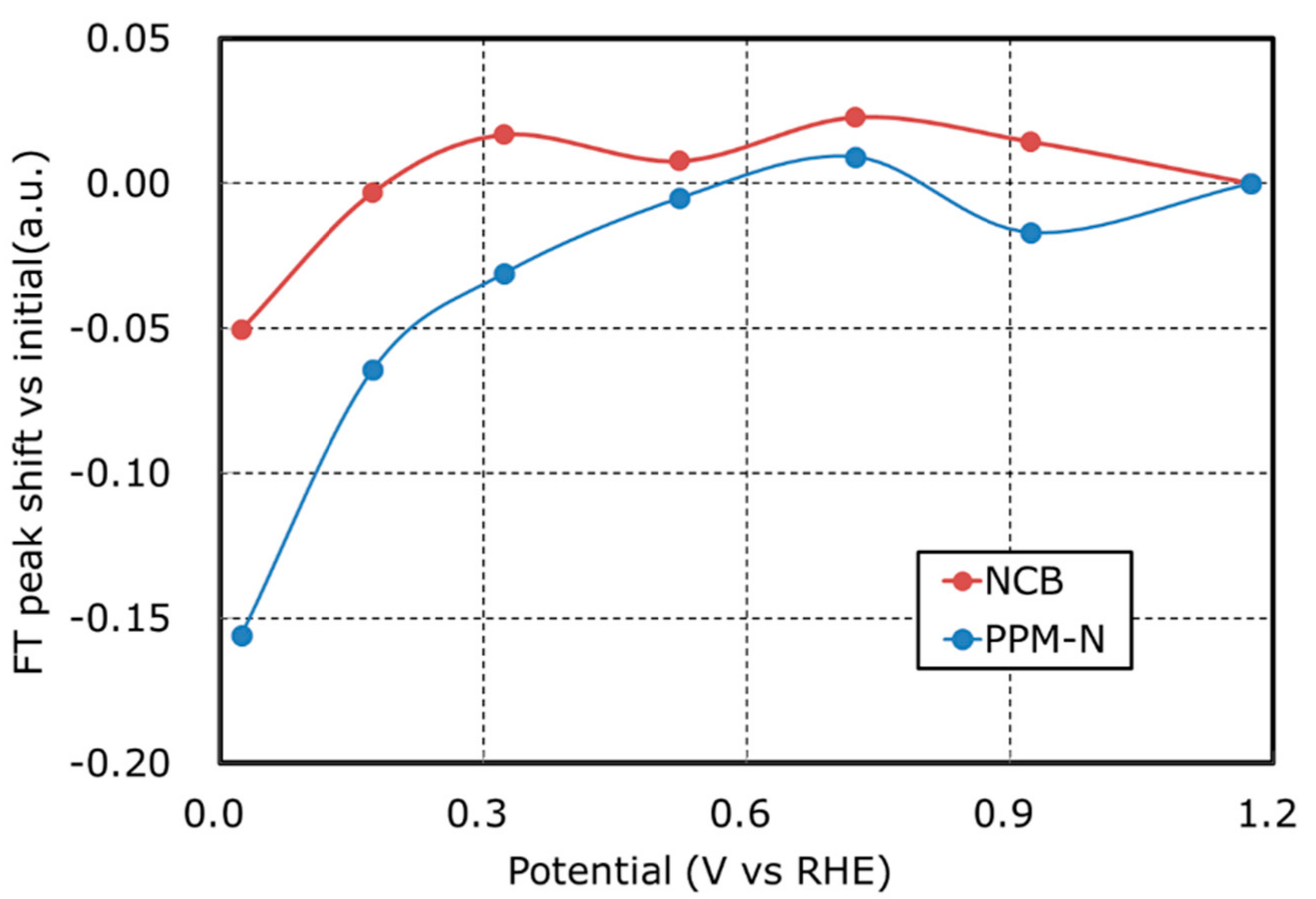
2.2. XAFS Data Collection and Analysis
2.3. Rotating Ring-Disk Electrode (RRDE) Preparation and Testing
(N = 0.38 in this work)
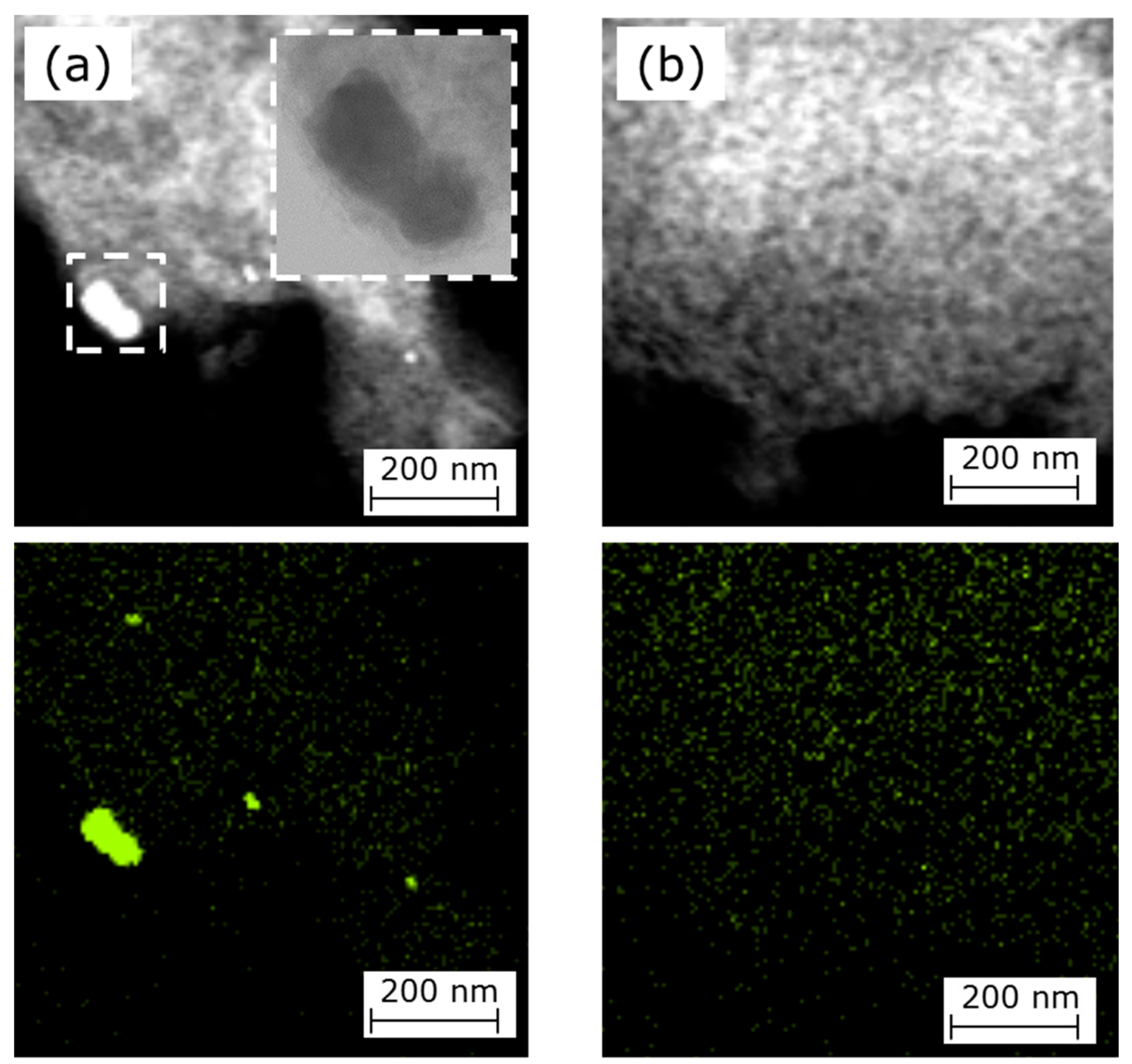
2.4. STEM Analysis
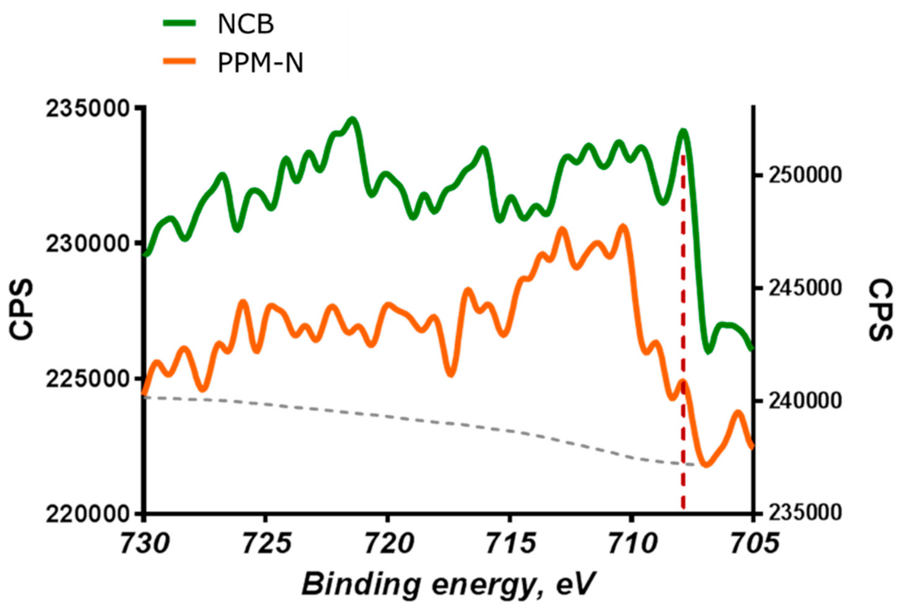
2.5. HAXPES Analysis
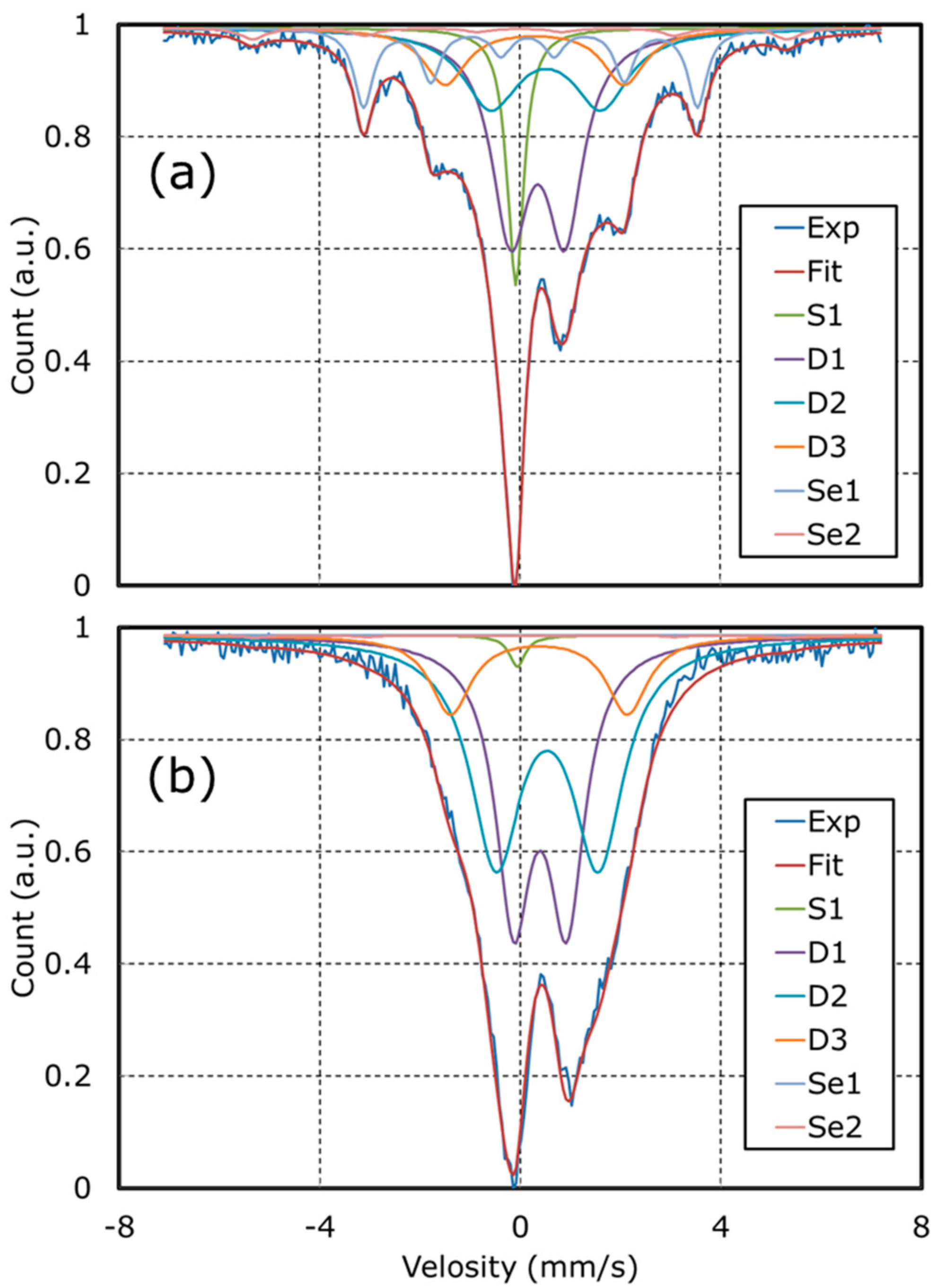
2.6. 57Fe Mößbauer Spectroscopy
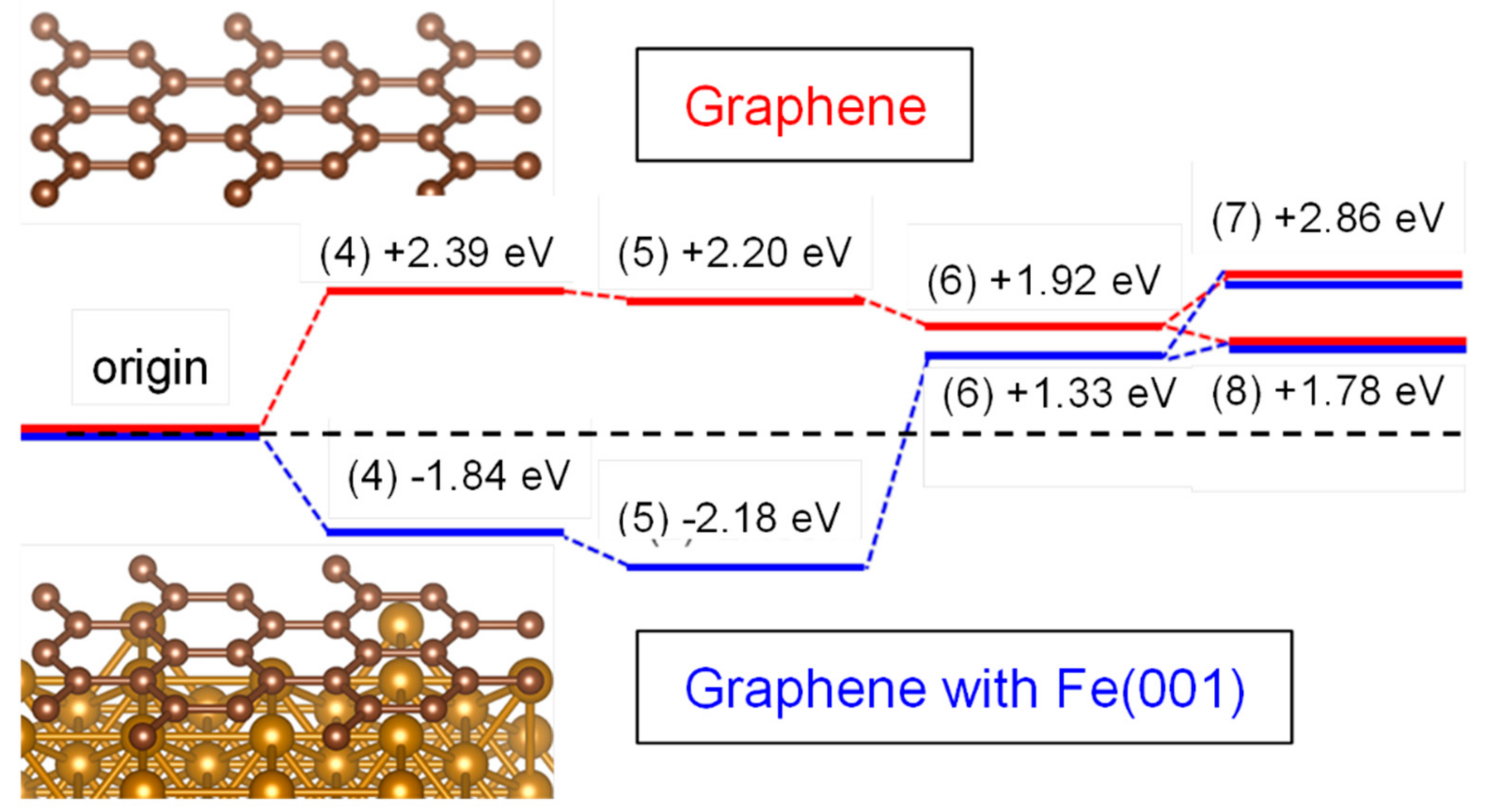
2.7. Computational Study
3. Results
4. Conclusions
Author Contributions
Funding
Acknowledgments
Conflicts of Interest
References
- Bashyam, R.; Zelenay, P. A class of non-precious metal composite catalysts for fuel cells. Nature 2006, 443, 63–66. [Google Scholar] [CrossRef] [PubMed]
- Lefèvre, M.; Proietti, E.; Jaouen, F.; Dodelet, J.P. Iron-Based Catalysts with Improved Oxygen Reduction Activity in Polymer Electrolyte Fuel Cells. Science 2009, 324, 71–74. [Google Scholar] [CrossRef] [PubMed]
- Proietti, E.; Jaouen, F.; Lefèvre, M.; Larouche, N.; Tian, J.; Herranz, J.; Dodelet, J.P. Iron-based cathode catalyst with enhanced power density in polymer electrolyte membrane fuel cells. Nat. Commun. 2011, 2, 416. [Google Scholar] [CrossRef] [PubMed]
- Serov, A.; Arthyushkova, K.; Niangar, E.; Wang, C.; Dale, N.; Jaouen, F.; Sougrati, M.T.; Jia, Q.; Mukerjee, S.; Atanassov, P. Nano-structured non-platinum catalysts for automotive fuel cell application. Nano Energy 2015, 16, 293–300. [Google Scholar] [CrossRef] [Green Version]
- Hossen, M.M.; Arthyushkova, K.; Atanassov, P.; Serov, A. Synthesis and characterization of high performing Fe-N-C catalyst for oxygen reduction reaction (ORR) in Alkaline Exchange Membrane Fuel Cells. J. Power Sources 2018, 375, 214–221. [Google Scholar] [CrossRef]
- Tammeveski, K.; Zagal, J.H. Electrocatalytic oxygen reduction on transition metal macrocyclic complexes for anion exchange membrane fuel cell application. Curr. Opin. Electrochem. 2018, 9, 207–213. [Google Scholar] [CrossRef]
- Wang, H.; Yin, F.X.; Chen, B.H.; He, X.B.; Lv, P.L.; Ye, C.Y.; Liu, D.J. ZIF-67 incorporated with carbon derived from pomelo peels: A highly efficient bifunctional catalyst for oxygen reduction/evolution reactions. Appl. Catal. B Environ. 2017, 205, 55–67. [Google Scholar] [CrossRef]
- Li, J.; Jaouen, F. Structure and activity of metal-centered coordination sites in pyrolyzed metal–nitrogen–carbon catalysts for the electrochemical reduction of O2. Curr. Opin. Electrochem. 2018, 9, 198–206. [Google Scholar] [CrossRef]
- Wang, X.X.; Hwang, S.; Pan, Y.T.; Chen, K.; He, Y.; Karakalos, S.; Zhang, H.; Spendelow, J.S.; Su, D.; Wu, G. Ordered Pt3Co Intermetallic Nanoparticles Derived from Metal–Organic Frameworks for Oxygen Reduction. Nano Lett. 2018, 18, 4163–4171. [Google Scholar] [CrossRef] [PubMed]
- Jia, Q.; Ramaswamy, N.; Tylus, U.; Strickland, K.; Li, J.; Serov, A.; Artyushkova, K.; Atanassov, P.; Anibal, J.; Gumeci, C.; et al. Spectroscopic insights into the nature of active sites in iron–nitrogen–carbon electrocatalysts for oxygen reduction in acid. Nano Energy 2016, 29, 65–82. [Google Scholar] [CrossRef]
- Chung, H.T.; Cullen, D.A.; Higgins, D.; Sneed, B.T.; Holby, E.F.; More, K.L.; Zelenay, P. Direct atomic-level insight into the active sites of a high-performance PGM-free ORR catalyst. Science 2017, 357, 479–484. [Google Scholar] [CrossRef] [PubMed]
- Strickland, K.; Miner, E.; Jia, Q.; Tylus, U.; Ramaswamy, N.; Liang, W.; Sougrati, M.T.; Jaouen, F.; Mukerjee, S. Highly active oxygen reduction non-platinum group metal electrocatalyst without direct metal–nitrogen coordination. Nat. Commun. 2015, 6, 7343. [Google Scholar] [CrossRef] [PubMed] [Green Version]
- Artyushkova, K.; Serov, A.; Carbonell, S.R.; Atanassov, P. Chemistry of Multitudinous Active Sites for Oxygen Reduction Reaction in Transition Metal–Nitrogen–Carbon Electrocatalysts. J. Phys. Chem. C 2015, 119, 25917–25928. [Google Scholar] [CrossRef]
- Chempath, S.; Einsla, B.; Pratt, L.R.; Macomber, C.S.; Boncella, J.M.; Rau, J.A.; Pivovar, B.S. Mechanism of Tetraalkylammonium Headgroup Degradation in Alkaline Fuel Cell Membranes. J. Phys. Chem. C 2008, 112, 3179–3182. [Google Scholar] [CrossRef]
- Macomber, C.S.; Boncella, J.M.; Pivovar, B.S.; Rau, J.A. Decomposition pathways of an alkaline fuel cell membrane material component via evolved gas analysis. J. Therm. Anal. Calorim. 2008, 93, 225–229. [Google Scholar] [CrossRef]
- Varcoe, J.R.; Slade, R.C.T. Prospects for Alkaline Anion-Exchange Membranes in Low Temperature Fuel Cells. Fuel Cells 2005, 5, 187–200. [Google Scholar] [CrossRef] [Green Version]
- Varcoe, J.R.; Slade, R.C.T. An electron-beam-grafted ETFE alkaline anion-exchange membrane in metal-cation-free solid-state alkaline fuel cells. Electrochem. Commun. 2006, 8, 839–843. [Google Scholar] [CrossRef] [Green Version]
- Varcoe, J.R.; Slade, R.C.T.; Yee, E.L.H.; Poynton, S.D.; Driscoll, D.J.; Apperley, D.C. Poly(ethylene-co-tetrafluoroethylene)-Derived Radiation-Grafted Anion-Exchange Membrane with Properties Specifically Tailored for Application in Metal-Cation-Free Alkaline Polymer Electrolyte Fuel Cells. Chem. Mater. 2007, 19, 2686–2693. [Google Scholar] [CrossRef]
- Danks, T.N.; Slade, R.C.T.; Varcoe, J.R. Comparison of PVDF- and FEP-based radiation-grafted alkaline anion-exchange membranes for use in low temperature portable DMFCs. J. Mater. Chem. 2002, 12, 3371–3373. [Google Scholar] [CrossRef] [Green Version]
- Danks, T.N.; Slade, R.C.T.; Varcoe, J.R. Alkaline anion-exchange radiation-grafted membranes for possible electrochemical application in fuel cells. J. Mater. Chem. 2003, 13, 712–721. [Google Scholar] [CrossRef] [Green Version]
- Yamada, K.; Asazawa, K.; Yasuda, K.; Ioroi, T.; Tanaka, H.; Miyazaki, Y.; Kobayashi, T. Investigation of PEM type direct hydrazine fuel cell. J. Power Sources 2003, 115, 236–242. [Google Scholar] [CrossRef]
- Asazawa, K.; Yamada, K.; Tanaka, H.; Oka, A.; Taniguchi, M.; Kobayashi, T. A platinum-free zero-carbon-emission easy fuelling direct hydrazine fuel cell for vehicles. Angew. Chem. Int. Ed. 2007, 46, 8024–8027. [Google Scholar] [CrossRef] [PubMed]
- Jasinski, R.A. New Fuel Cell Cathode Catalyst. Nature 1964, 201, 1212–1213. [Google Scholar] [CrossRef]
- Serov, A.; Min, M.; Chai, G.; Han, S.; Seo, S.J.; Park, Y.; Kim, H.; Kwak, C. Electroreduction of oxygen over iron macrocyclic catalysts for DMFC applications. J. Appl. Electrochem. 2009, 39, 1509–1516. [Google Scholar] [CrossRef]
- Sebastian, D.; Serov, A.; Artyushkova, K.; Atanassov, P.; Arico, A.S.; Baglio, V. Performance, methanol tolerance and stability of Fe-aminobenzimidazole derived catalyst for direct methanol fuel cells. J. Power Sources 2016, 319, 235–246. [Google Scholar] [CrossRef]
- Janarthanana, R.; Serov, A.; Kishore Pilli, S.; Gamarra, D.A.; Atanassov, P.; Hibbs, M.R.; Herring, A.M. Direct Methanol Anion Exchange Membrane Fuel Cell with a Non-Platinum Group Metal Cathode based on Iron-Aminoantipyrine Catalyst. Electrochim. Acta 2015, 175, 202–208. [Google Scholar] [CrossRef] [Green Version]
- Serov, A.; Atryushkova, K.; Andersen, N.I.; Stariha, S.; Atanassov, P. Original Mechanochemical Synthesis of Non-Platinum Group Metals Oxygen Reduction Reaction Catalysts Assisted by Sacrificial Support Method. Electrochim. Acta 2015, 179, 154–160. [Google Scholar] [CrossRef]
- Serov, A.; Zulevi, B.; Artyushkova, K.; Atanassov, P.; Zhang, G.; Chenitz, R.; Lefèvree, M.; Dodelet, J.-P.; Sun, S.; Pann, S.; et al. Platinum Group Metal-Free Oxygen Reduction Reaction Electrocatalysts from Fe-N-C Family: Activity, Durability and Manufacturability. In ECS Meetting Abstract; MA2017-02 1498; The Electrochemical Society: National Harbor, MD, USA, 2017. [Google Scholar]
- Stone, D.; Whalley, L.K.; Heard, D.E. Tropospheric OH and HO2 radicals: Field measurements and model comparisons. Chem. Soc. Rev. 2012, 41, 6348–6404. [Google Scholar] [CrossRef] [PubMed]
- Serov, A.; Workman, M.J.; Arthyushkova, K.; Atanassov, P.; McCool, G.; McKinney, S.; Romero, H.; Halevi, B.; Stephenson, T. Highly stable precious metal-free cathode catalyst for fuel cell application. J. Power Sources 2016, 327, 557–564. [Google Scholar] [CrossRef]
- Stariha, S.; Atryushkova, K.; Workman, M.J.; Serov, A.; Mckinney, S.; Halevi, B.; Atanassov, P. PGM-free Fe-N-C catalysts for oxygen reduction reaction: Catalyst layer design. J. Power Sources 2016, 326, 43–49. [Google Scholar] [CrossRef] [Green Version]
- Asazawa, K.; Kishi, H.; Tanaka, H.; Matsumura, D.; Tamura, K.; Nishihata, Y.; Saputro, A.G.; Nakanishi, H.; Kasai, H.; Atryushkova, K.; et al. In Situ XAFS and HAXPES Analysis and Theoretical Study of Cobalt Polypyrrole Incorporated on Carbon (CoPPyC) Oxygen Reduction Reaction Catalysts for Anion-Exchange Membrane Fuel Cells. J. Phys. Chem. C 2014, 118, 25480–25486. [Google Scholar] [CrossRef]
- Sakamoto, T.; Kishi, H.; Yamaguchi, S.; Matsumura, D.; Tamura, K.; Hori, A.; Horiuchi, Y.; Serov, A.; Atryushkova, K.; Atanassov, P.; et al. Mechanism Study of Hydrazine Electrooxidation Reaction on Nickel Oxide Surface in Alkaline Electrolyte by In Situ XAFS. J. Electrochem. Soc. 2016, 10, H951–H957. [Google Scholar] [CrossRef]
- Kramm, U.I.; Lefèvre, M.; Larouche, N.; Schmeisser, D.; Dodelet, J.P. Correlations between Mass Activity and Physicochemical Properties of Fe/N/C Catalysts for the ORR in PEM Fuel Cell via 57Fe Mössbauer Spectroscopy and Other Techniques. J. Am. Chem. Soc. 2014, 136, 978–985. [Google Scholar] [CrossRef] [PubMed]
- Kramm, U.I.; Herranz, J.; Larouche, N.; Arruda, T.M.; Lefèvre, M.; Jaouen, F.; Bogdanoff, P.; Fiechter, S.; Wurmbach, I.A.; Mukerjee, S.; et al. Structure of the catalytic sites in Fe/N/C-catalysts for O2-reduction in PEM fuel cells. Phys. Chem. Chem. Phys. 2012, 14, 11673–11688. [Google Scholar] [CrossRef] [PubMed]
- Shi, Z.; Liu, H.; Lee, K.; Dy, E.; Chlistunoff, J.; Blair, M.; Zelenay, P.; Zhang, J.; Liu, J.S. Theoretical Study of Possible Active Site Structures in Cobalt-Polypyrrole Catalysts for Oxygen Reduction Reaction. J. Phys. Chem. C 2011, 115, 16672–16680. [Google Scholar] [CrossRef]
- Saputro, A.G.; Kasai, H. Comparative Study on the Catalytic Activity of the TM–N2 Active Sites (TM = Mn, Fe, Co, Ni) in the Oxygen Reduction Reaction: Density Functional Theory Study. J. Phys. Soc. Jpn. 2013, 82, 114704–114715. [Google Scholar] [CrossRef]
- Stephens, P.J.; Devlin, F.J.; Chabalowski, C.F.; Frisch, M.J. Ab Initio Calculation of Vibrational Absorption and Circular Dichroism Spectra Using Density Functional Force Fields. J. Phys. Chem. 1994, 98, 11623–11627. [Google Scholar] [CrossRef]
- Suntivich, J.; Gasteiger, H.A.; Yabuuchi, N.; Nakanishi, H.; Goodenough, J.B.; Horn, Y.S. Design principles for oxygen-reduction activity on perovskite oxide catalysts for fuel cells and metal–air batteries. Nat. Chem. 2011, 3, 546–550. [Google Scholar] [CrossRef] [PubMed]
- Geniès, L.; Faure, R.; Durand, R. Electrochemical reduction of oxygen on platinum nanoparticles in alkaline media. Electrochim. Acta 1998, 44, 1317–1327. [Google Scholar] [CrossRef]
- Escano, M.C.S.; Nakanishi, H.; Kasai, H. Spin-polarized density functional theory study of reactivity of diatomic molecule on bimetallic system: The case of O2 dissociative adsorption on Pt monolayer on Fe(001). J. Phys. Chem. A 2009, 113, 14302–14307. [Google Scholar] [CrossRef] [PubMed]
- Zhang, J. PEM Fuel Cell. Electrocatalysts and Catalyst Layers; Springer Nature Switzerland AG: Basel, Switzerland, 2008; ISBN 978-1-84800-935-6. [Google Scholar]


| Catalyst (Abbreviation) | Precursor | 1st Acid Treatment | 2nd Acid Treatment |
|---|---|---|---|
| NCB | Nicarbazin | 20 wt. % HF | - |
| NCB-N | Nicarbazin | 20 wt. % HF | 1 M HNO3 |
| PPM-N | Pipemidic acid | 20 wt. % HF | 1 M HNO3 |
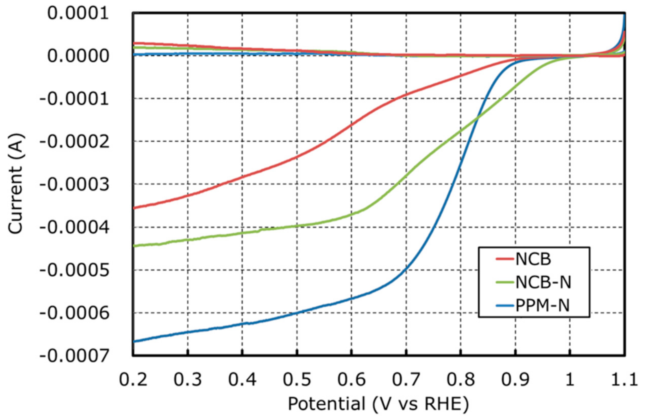
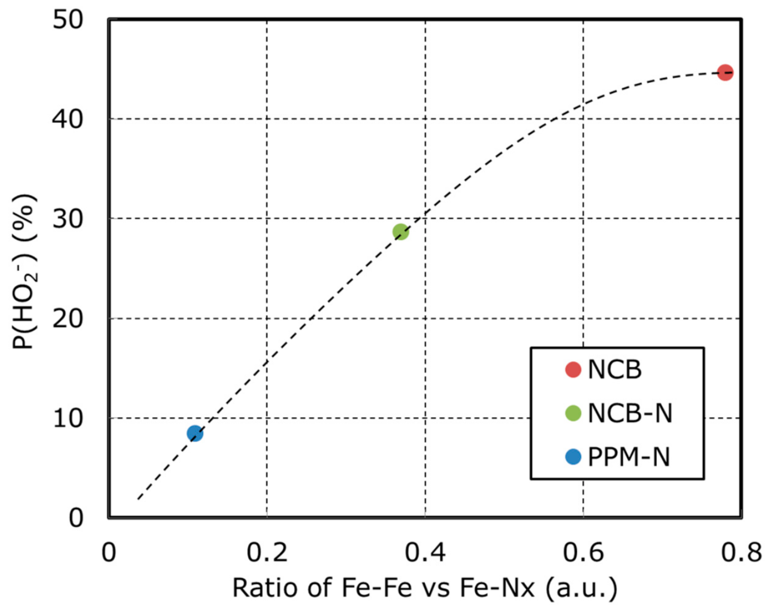
| Catalyst | P(HO2−) N = 0.38 | Id (mA) @ 0.2 V vs. RHE | Onset Potential (V) vs. RHE | Half Wave Potential (V) vs. RHE |
|---|---|---|---|---|
| NCB | 44.6 | −0.35 | 1.01 | 0.57 |
| NCB-N | 28.6 | −0.44 | 1.04 | 0.74 |
| PPM-N | 8.4 | −0.67 | 1.04 | 0.78 |
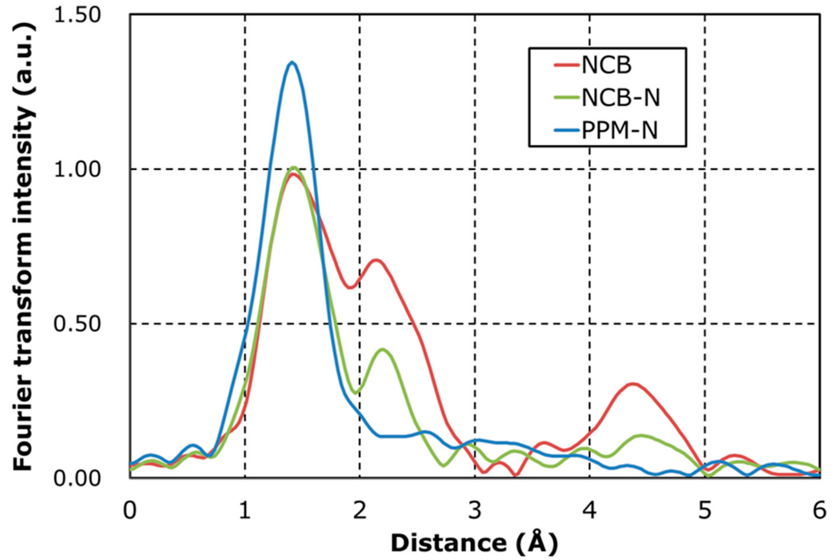
| Catalyst | Fe-Nx (Area) | Fe-Fe (Area) | Fe-Fe/Fe-Nx (ratio) |
|---|---|---|---|
| NCB | 0.68 | 0.53 | 0.78 |
| NCB-N | 0.65 | 0.24 | 0.37 |
| PPM-N | 0.81 | 0.09 | 0.11 |
| Catalyst | S1 (γ-Fe) | Se1 (FeC) | Se2 (α-Fe) | D1 | D2 | D3 |
|---|---|---|---|---|---|---|
| NCB | 10.8 | 15.3 | 2.9 | 36.9 | 21.8 | 12.3 |
| NCB-N | 10.0 | 0.0 | 0.7 | 36.1 | 37.0 | 16.2 |
| PPM-N | 1.1 | 0.0 | 0.5 | 39.8 | 45.7 | 12.9 |
© 2018 by the authors. Licensee MDPI, Basel, Switzerland. This article is an open access article distributed under the terms and conditions of the Creative Commons Attribution (CC BY) license (http://creativecommons.org/licenses/by/4.0/).
Share and Cite
Kishi, H.; Sakamoto, T.; Asazawa, K.; Yamaguchi, S.; Kato, T.; Zulevi, B.; Serov, A.; Artyushkova, K.; Atanassov, P.; Matsumura, D.; et al. Structure of Active Sites of Fe-N-C Nano-Catalysts for Alkaline Exchange Membrane Fuel Cells. Nanomaterials 2018, 8, 965. https://doi.org/10.3390/nano8120965
Kishi H, Sakamoto T, Asazawa K, Yamaguchi S, Kato T, Zulevi B, Serov A, Artyushkova K, Atanassov P, Matsumura D, et al. Structure of Active Sites of Fe-N-C Nano-Catalysts for Alkaline Exchange Membrane Fuel Cells. Nanomaterials. 2018; 8(12):965. https://doi.org/10.3390/nano8120965
Chicago/Turabian StyleKishi, Hirofumi, Tomokazu Sakamoto, Koichiro Asazawa, Susumu Yamaguchi, Takeshi Kato, Barr Zulevi, Alexey Serov, Kateryna Artyushkova, Plamen Atanassov, Daiju Matsumura, and et al. 2018. "Structure of Active Sites of Fe-N-C Nano-Catalysts for Alkaline Exchange Membrane Fuel Cells" Nanomaterials 8, no. 12: 965. https://doi.org/10.3390/nano8120965