
The Lightweight Design of a Seismic Low-Yield-Strength Steel Shear Panel Damper

Abstract
:1. Introduction
2. Test Procedures
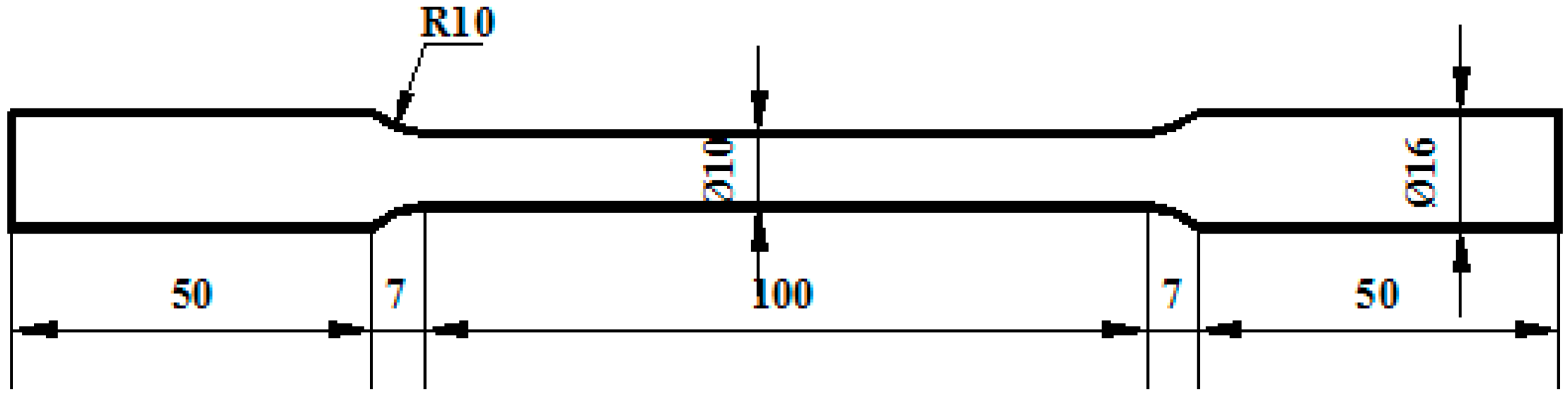
2.1. Material Property Test
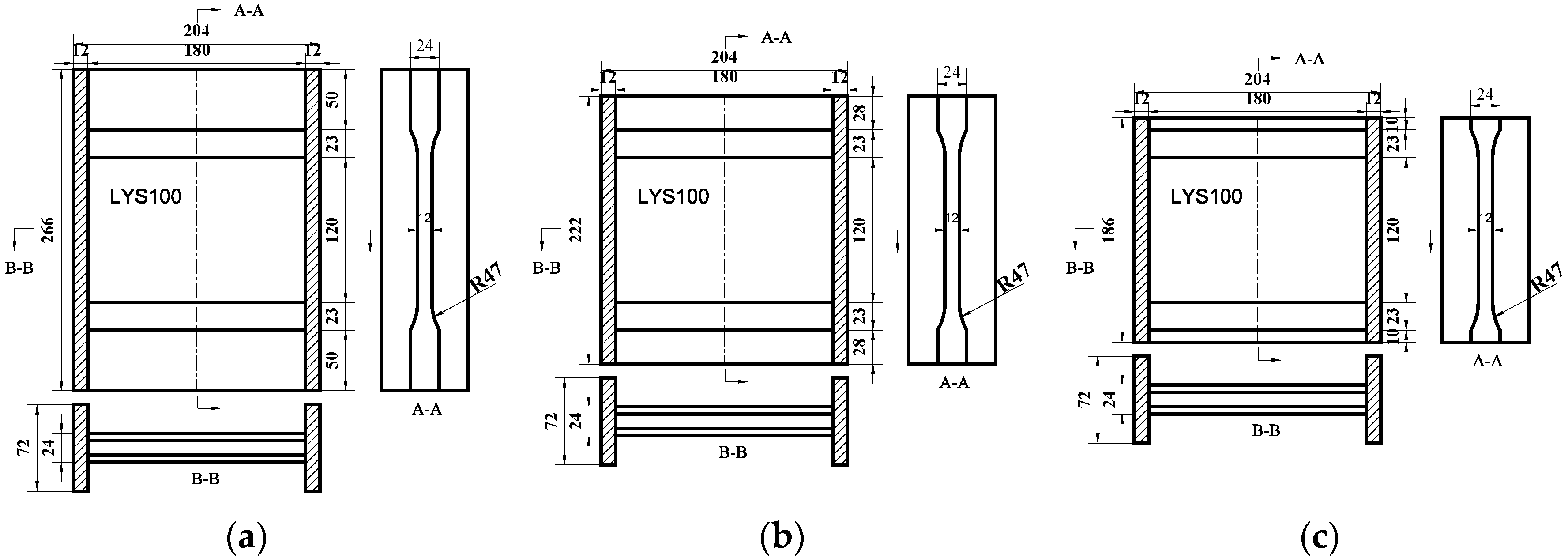
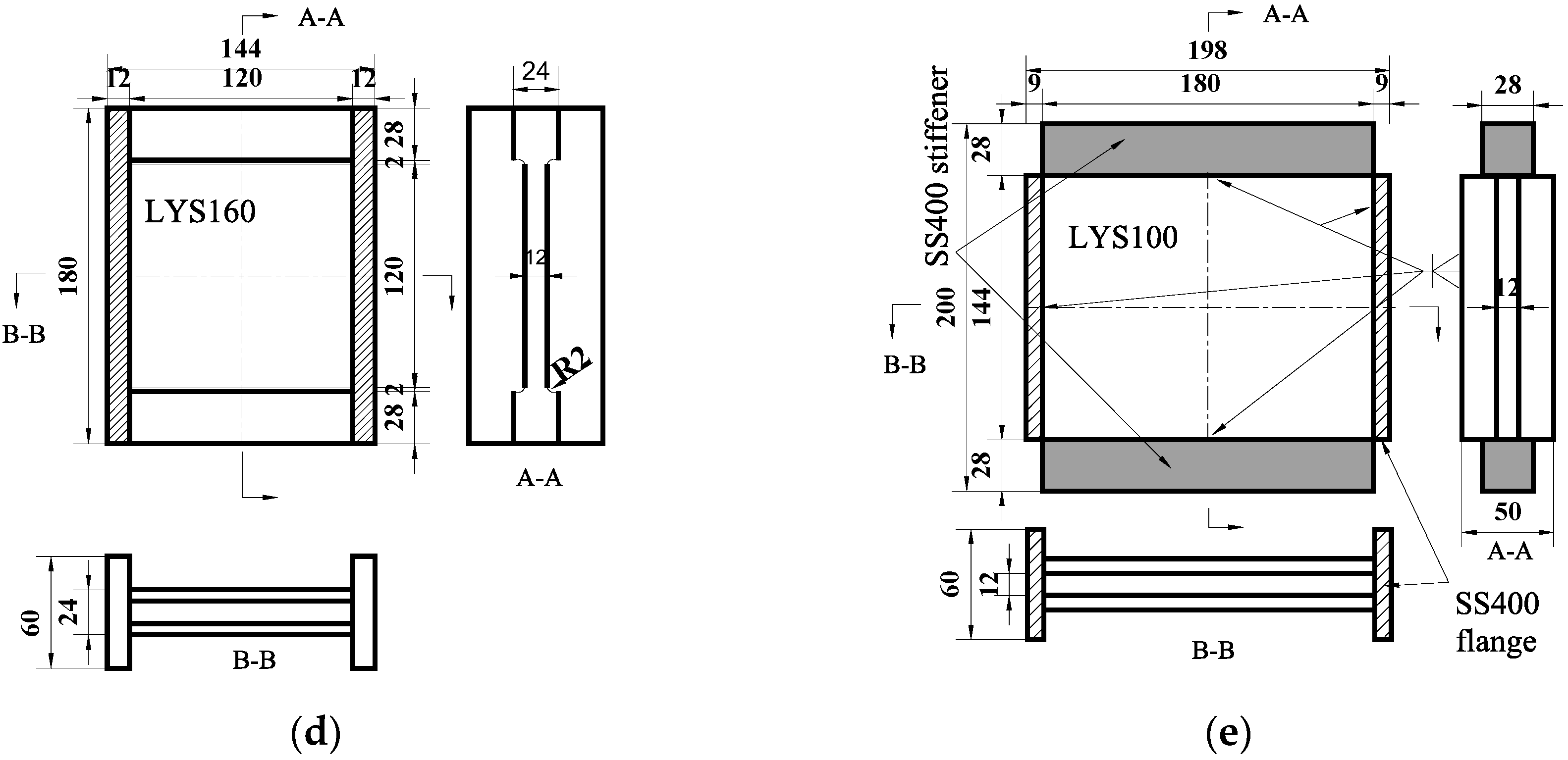
2.2. The Lightweight Design of Shear Panel Damper
2.2.1. Concept of Lightweight Design
- (1)
- Lightweight Design of Boundary Constraints
- (a)
- Stiffener
- (b)
- Transition Arc
- (c)
- Rib Material
- (2)
- Generality of Lightweight Design
- (3)
- Shear Force and Lightweight Design
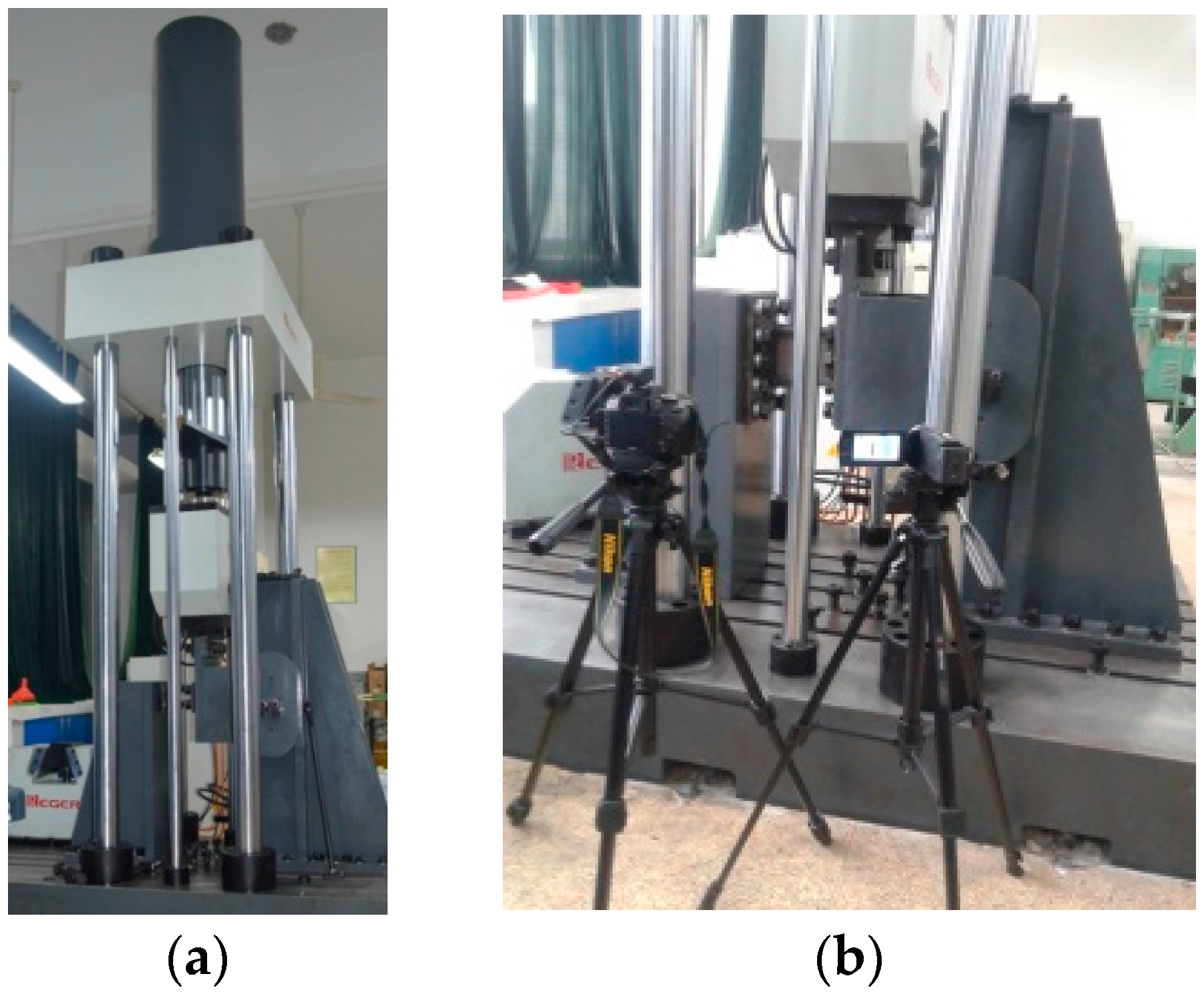
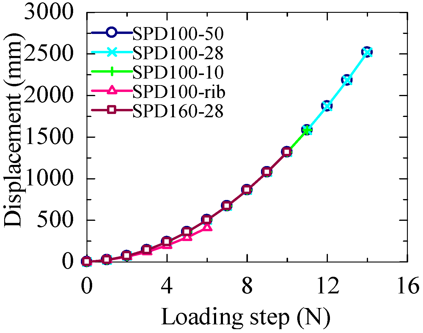
2.2.2. Test Setup
3. Test Results and Discussion
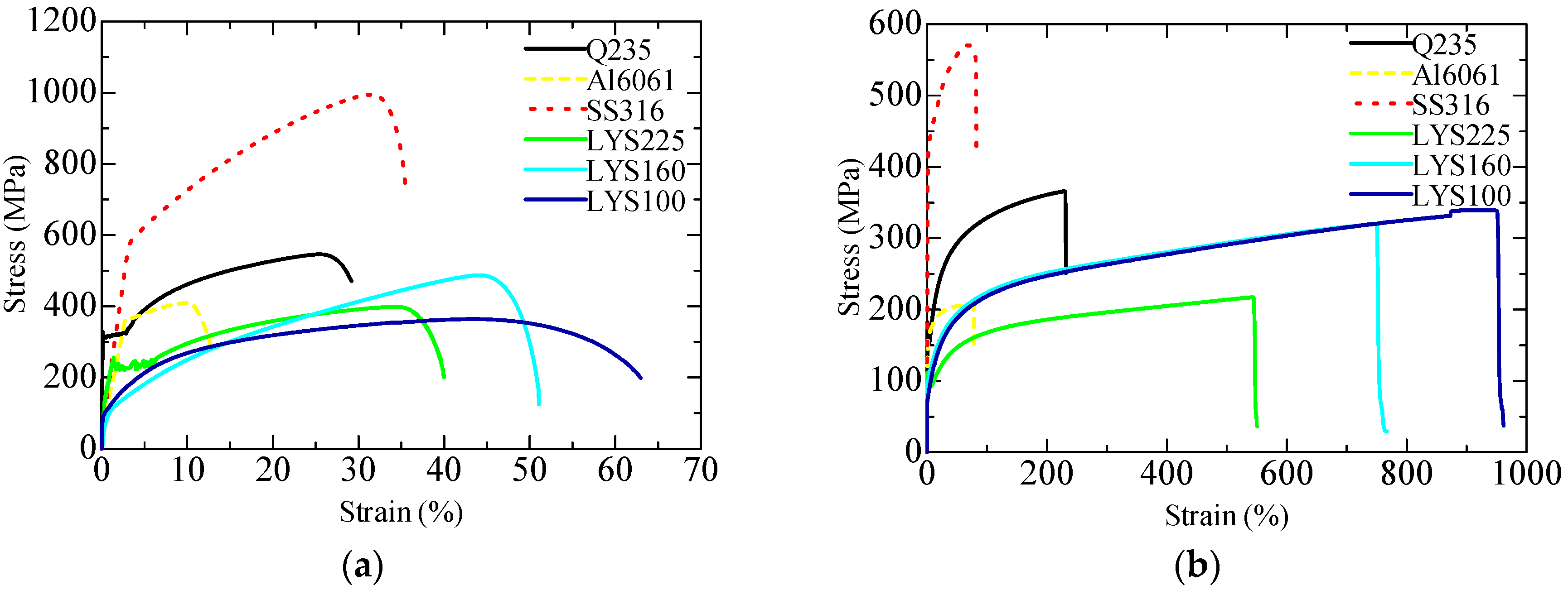
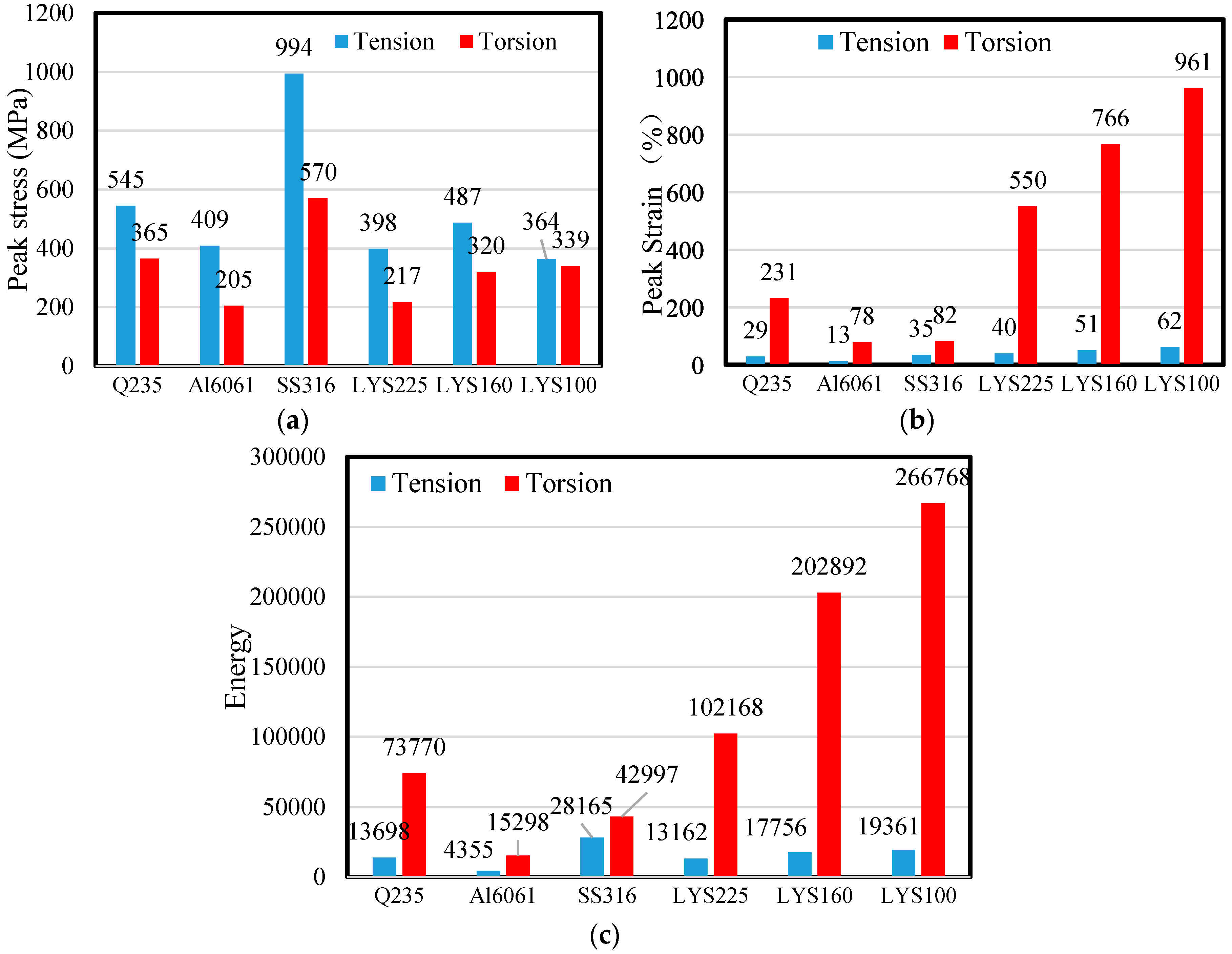
3.1. Material Test Results and Discussion
3.2. Structural Test Results
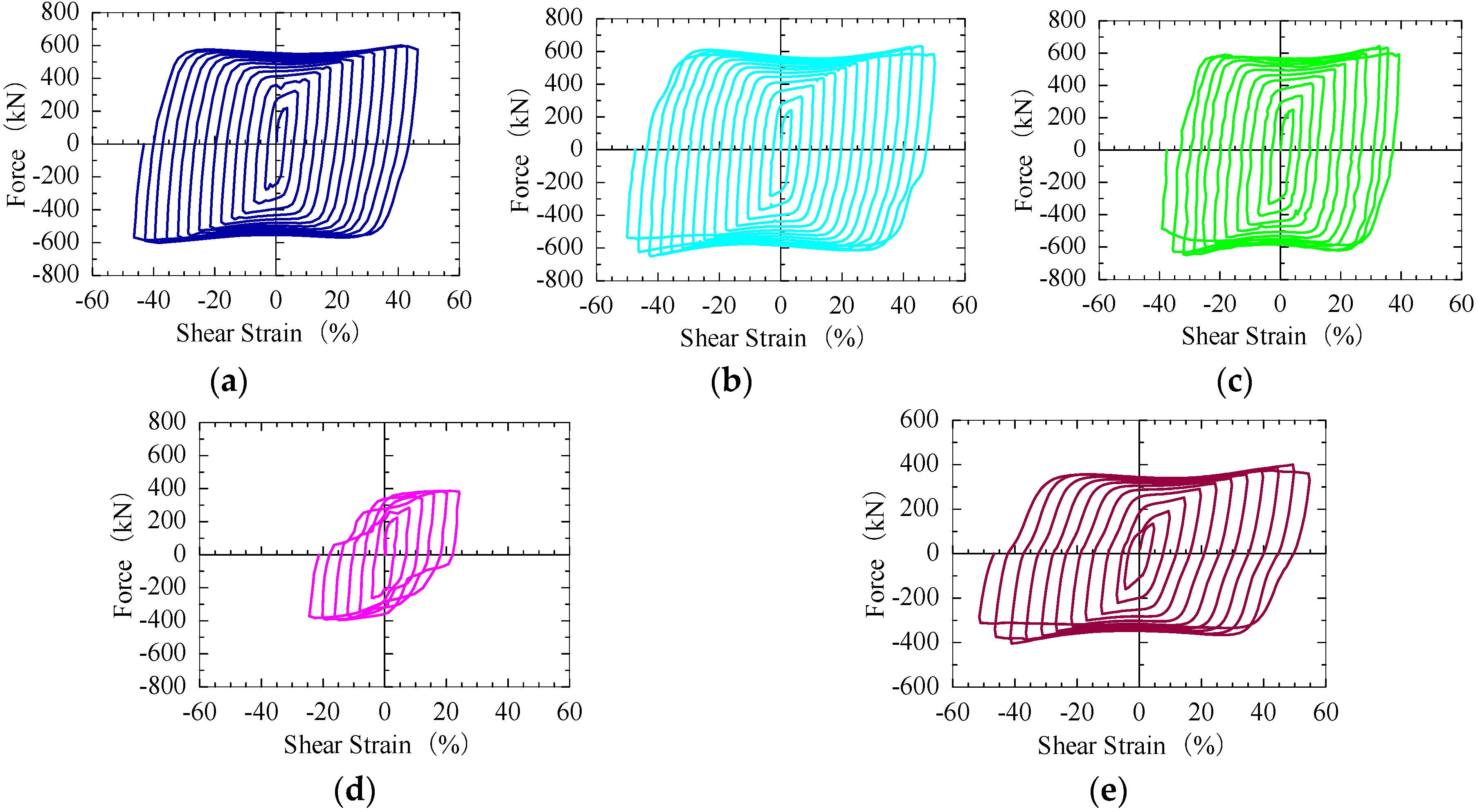
3.2.1. Hysteretic Curve
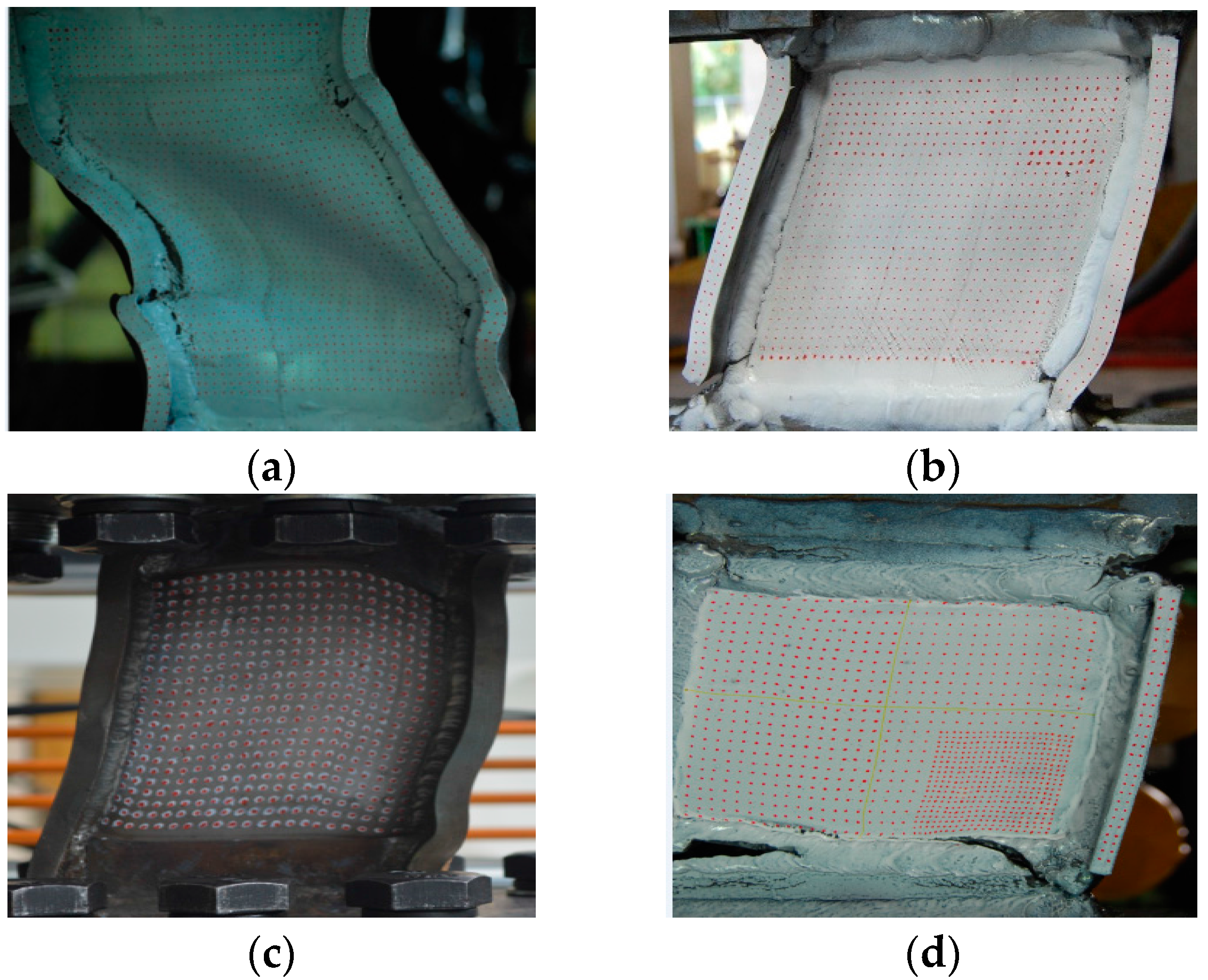
3.2.2. Failure Mode
3.3. Discussion on Lightweight Design
3.3.1. Optimization of Boundary Constraints
- (1)
- Stiffener
- (2)
- Transition Arc
- (3)
- Rib
3.3.2. Generality of Lightweight Design
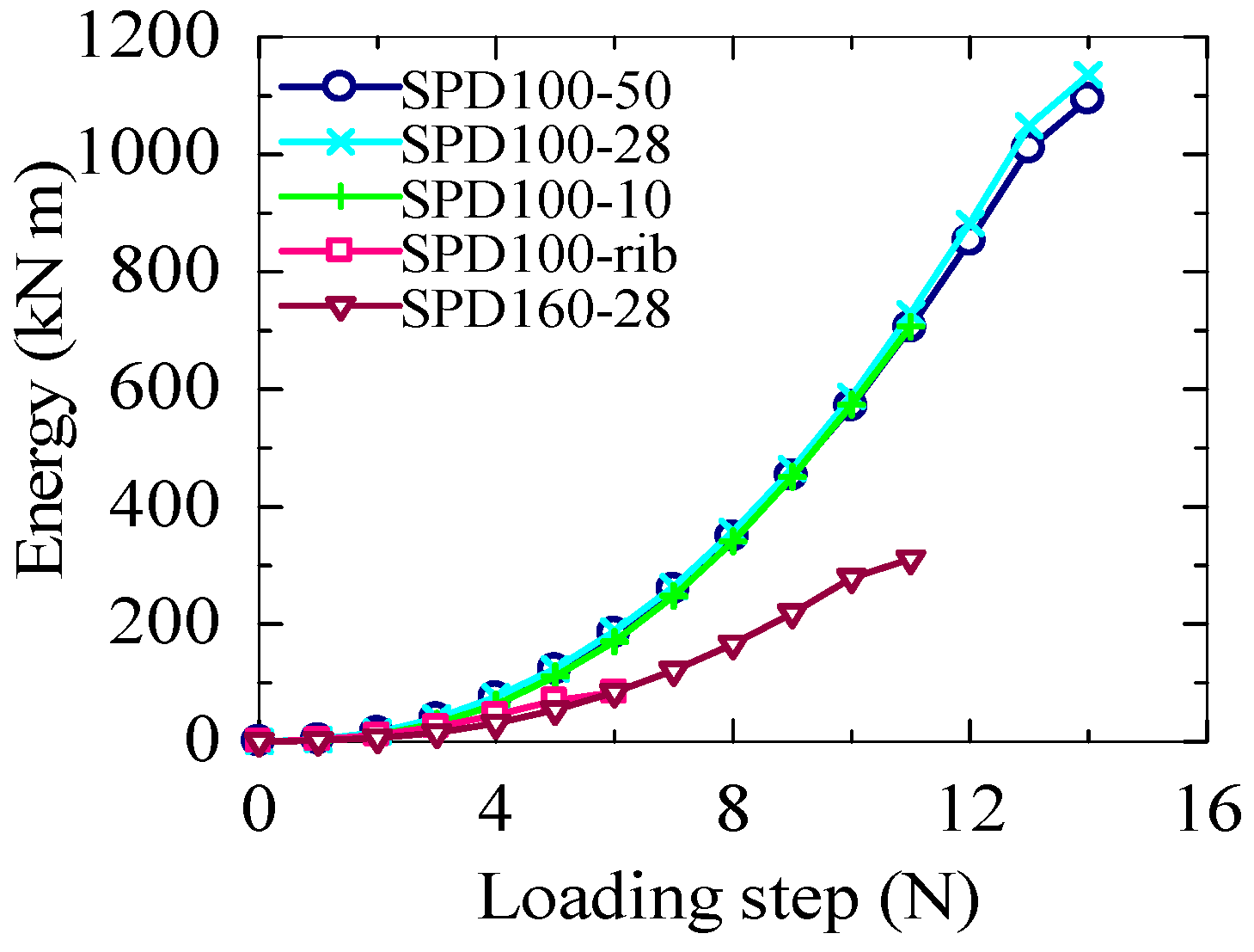
3.3.3. Shear Force and Lightweight Design
3.3.4. Performance of the Lightweight Damper
4. Conclusions
- LYS100 is found to exhibit superplastic deformation behavior under shear. The plastic properties of materials under shear cannot be simply predicted by the tensile stress–strain curves under uniaxial tension.
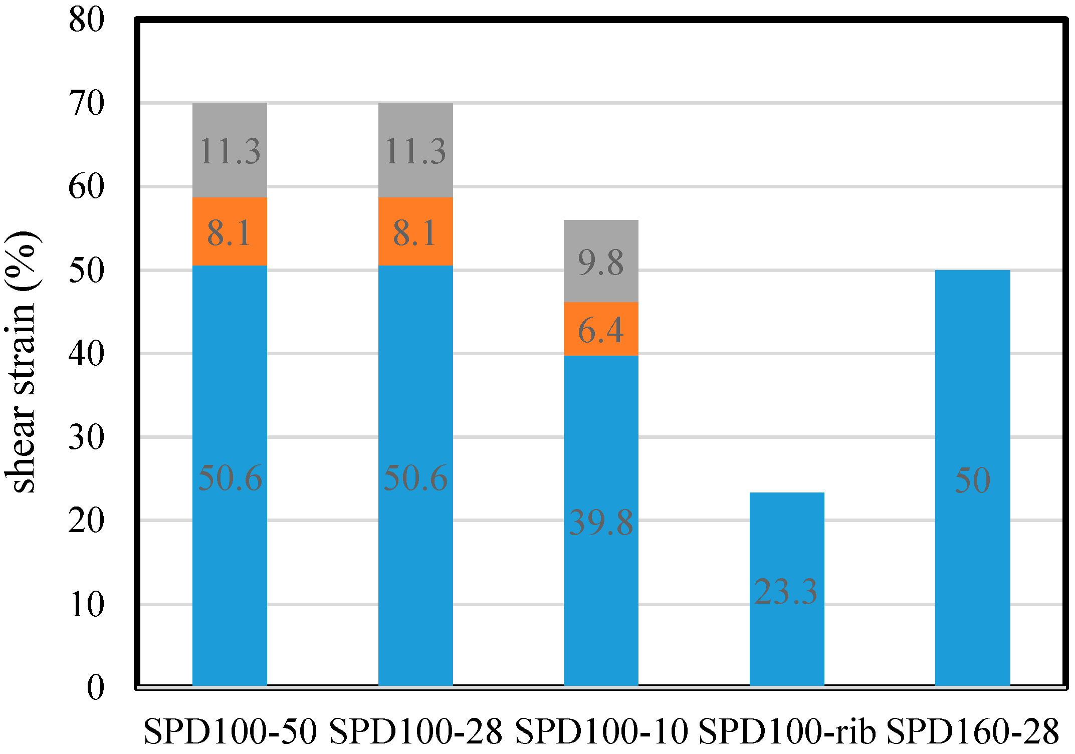
- The ultimate uniaxial tensile strain of LYS160 is approximately 50%. However, the maximum shear strain of the LYSPD is more than 50% under the ±5% incremental reciprocal loading sequence. When the principal stress is consistent with the maximum energy consumption capacity of the damping structure, the lightweight design goal of the dampers can be accomplished.
- Boundary constraints are important elements from the viewpoint of ensuring large deformation, and they dominate the adjustable force of the damper.
- Both sufficient stiffness and high ductility of the boundary constraint components are necessary for ensuring large deformation and large energy consumption. Lightweight design of the dampers cannot be achieved by using boundary constraints made from low-ductility metallic damping materials such as ordinary carbon steel.
- Optimal selection of the damping materials based on the maximum energy consumption criterion is beneficial for the lightweight design of the SPD. Although the density of aluminum is rather low, the maximum energy consumption per unit mass of Al6061 is only 1/6 times that of LYS100. LYS is the most optimal material among all the considered metallic damping materials for achieving the lightweight design goal of seismic dampers.
Acknowledgments
Author Contributions
Conflicts of Interest
References
- Kelly, J.M.; Skinner, R.I.; Heine, A.J. Mechanisms of energy absorption in special devices of use in earthquake resistant structures. Bull. N. Z. Soc. Earthq. Eng. 1972, 5, 63–88. [Google Scholar]
- Bagheri, S.; Barghian, M.; Saieri, F.; Farzinfar, A. U-shaped metallic-yielding damper in building structures: Seismic behavior and comparison with a friction damper. Structures 2015, 3, 163–171. [Google Scholar] [CrossRef]
- Lee, C.H.; Ju, Y.K.; Min, J.K.; Lho, S.H.; Kim, S.D. Non-uniform steel strip dampers subjected to cyclic loadings. Eng. Struct. 2015, 99, 192–204. [Google Scholar] [CrossRef]
- Takeuchi, T.; Hajjar, J.F.; Matsui, R.; Nishimoto, K.; Aiken, I.D. Effect of local buckling core plate restraint in buckling restrained braces. Eng. Struct. 2012, 44, 304–311. [Google Scholar] [CrossRef]
- Zhao, J.; Wu, B.; Ou, J. Global stability design method of buckling-restrained braces considering end bending moment transfer: Discussion on pinned connections with collars. Eng. Struct. 2013, 49, 947–962. [Google Scholar] [CrossRef]
- Piedrafita, D.; Cahis, X.; Simon, E.; Comas, J. A new modular buckling restrained brace for seismic resistant buildings. Eng. Struct. 2013, 56, 1967–1975. [Google Scholar] [CrossRef]
- De Matteis, G.; Mazzolani, F.M.; Panico, S. Pure aluminium shear panels as dissipative devices in moment-resisting steel frames. Earthq. Eng. Struct. Dyn. 2007, 36, 841–859. [Google Scholar] [CrossRef]
- Chan, R.W.K.; Albermani, F.; Williams, M.S. Evaluation of yielding shear panel device for passive energy dissipation. J. Constr. Steel Res. 2009, 65, 260–268. [Google Scholar] [CrossRef]
- Zhang, C.; Aoki, T.; Zhang, Q.; Wu, M. Experimental investigation on the low-yield-strength steel shear panel damper under different loading. J. Constr. Steel Res. 2013, 84, 105–113. [Google Scholar] [CrossRef]
- Tubaldi, E.; Barbato, M.; Dall’Asta, A. Performance-based seismic risk assessment for buildings equipped with linear and nonlinear viscous dampers. Eng. Struct. 2014, 78, 90–99. [Google Scholar] [CrossRef]
- Le Maoût, N.; Verron, E.; Bégué, J. On the use of discontinuous elastomer patches to optimize the damping properties of composite sandwich plates. Compos. Struct. 2011, 93, 3057–3062. [Google Scholar] [CrossRef]
- Mazza, F. Nonlinear seismic analysis of unsymmetric-plan structures retrofitted by hysteretic damped braces. Bull. Earthq. Eng. 2016, 14, 1311–1331. [Google Scholar] [CrossRef]
- Bagheria, S.; Hadidi, A.; Alilou, A. Heightwise distribution of stiffness ratio for optimum seismic design of steel frames with metallic-yielding dampers. Procedia Eng. 2011, 14, 2891–2898. [Google Scholar] [CrossRef]
- Mazza, F.; Mazza, M.; Vulcano, A. Displacement-based seismic design of hysteretic damped braces for retrofitting in-elevation irregular r.c. framed structures. Soil Dyn. Earthq. Eng. 2015, 69, 115–124. [Google Scholar] [CrossRef]
- Shih, M.H.; Sung, W.P. A model for hysteretic behavior of rhombic low yield strength steel added damping and stiffness. Comput. Struct. 2005, 83, 895–908. [Google Scholar] [CrossRef]
- Zhang, C.; Aoki, T.; Zhang, Q.; Wu, M. The performance of low-yield-strength steel shear-panel damper with and without buckling. Mater. Struct. 2015, 48, 1233–1242. [Google Scholar] [CrossRef]
- De Matteis, G.; Brando, G.; Mazzolani, F.M. Hysteretic behaviour of bracing-type pure aluminium shear panels by experimental tests. Earthq. Eng. Struct. Dyn. 2011, 40, 1143–1162. [Google Scholar] [CrossRef]
- Lee, S.C.; Lee, D.S.; Yoo, C.H. Design of intermediate transverse stiffeners for shear web panels. Eng. Struct. 2014, 75, 27–38. [Google Scholar] [CrossRef]
- De Matteis, G.; Panico, S.; Mazzolani, F.M. Experimental tests on pure aluminium shear panels with welded stiffeners. Eng. Struct. 2008, 30, 1734–1744. [Google Scholar] [CrossRef]
- Zhang, C.; Zhang, Z.; Shi, J. Development of high deformation capacity low yield strength steel shear panel damper. J. Constr. Steel Res. 2012, 75, 116–130. [Google Scholar] [CrossRef]
- Ghabraie, K.; Chan, R.; Huang, X.; Xie, Y.M. Shape optimization of metallic yielding devices for passive mitigation of seismic energy. Eng. Struct. 2010, 32, 2258–2267. [Google Scholar] [CrossRef] [Green Version]
- Liu, Y.; Shimoda, M. Shape optimization of shear panel damper for improving the deformation ability under cyclic loading. Struct. Multidisc. Optim. 2013, 48, 427–435. [Google Scholar] [CrossRef]
- Rai, D.C.; Annam, P.K.; Pradhan, T. Seismic testing of steel braced frames with aluminum shear yielding dampers. Eng. Struct. 2013, 46, 737–747. [Google Scholar] [CrossRef]
- De Matteis, G.; Brando, G.; Mazzolani, F.M. Pure aluminium: An innovative material for structural applications in seismic engineering. Constr. Build. Mater. 2012, 26, 677–686. [Google Scholar] [CrossRef]
- Deng, K.; Pan, P.; Li, W.; Xue, Y. Development of a buckling restrained shear panel damper. J. Constr. Steel Res. 2015, 106, 311–321. [Google Scholar] [CrossRef]
- Brando, G.; D’Agostino, F.; De Matteis, G. Experimental tests of a new hysteretic damper made of buckling inhibited shear panels. Mater. Struct. 2013, 46, 2121–2133. [Google Scholar] [CrossRef]
- Brando, G.; De Matteis, G. Design of low strength-high hardening metal multi-stiffened shear plates. Eng. Struct. 2014, 60, 2–10. [Google Scholar] [CrossRef]
- Sun, Y.; Ma, J.; Li, B.; Guo, Z. Predication of nonlinear heat transfer in a convective-radiative fin with temperature dependent properties by the collocation spectral method. Numer. Heat Transfer, Part B 2016, 69, 63–68. [Google Scholar] [CrossRef]
- Estrada, I.; Real, E.; Mirambell, E. A new developed expression to determine more realistically the shear buckling stress in steel plate structures. J. Constr. Steel Res. 2008, 64, 737–747. [Google Scholar] [CrossRef]
- Alinia, M.M.; Gheitasi, A.; Erfani, S. Plastic shear buckling of unstiffened stocky plates. J. Constr. Steel Res. 2009, 65, 1631–1643. [Google Scholar] [CrossRef]
- Liu, Y.; Aoki, T.; Takaku, T.; Fukumoto, Y. Cyclic loading tests of shear panel damper made of low yield steel. J. Struct. Constr. Eng. 2007, 53A, 560–567. (In Japanese) [Google Scholar]


| No. | Name | Material | Diameter (mm) | Length (mm) | Test Type | |
|---|---|---|---|---|---|---|
| Tension | Torsion | |||||
| 1 | Q235 | Ordinary carbon steel | 10 | 100 | Ten1 | Tor1 |
| 2 | Q235 | Ten2 | Tor2 | |||
| 3 | Q235 | Ten3 | Tor3 | |||
| 4 | AL6061 | Aluminum 6061 | Ten4 | Tor4 | ||
| 5 | AL6061 | Ten5 | Tor5 | |||
| 6 | AL6061 | Ten6 | Tor6 | |||
| 7 | SS316 | Stainless steel 316 | Ten7 | Tor7 | ||
| 8 | SS316 | Ten8 | Tor8 | |||
| 9 | SS316 | Ten9 | Tor9 | |||
| 10 | LYS225 | Low-yield-strength steel 225 | Ten10 | Tor10 | ||
| 11 | LYS225 | Ten11 | Tor11 | |||
| 12 | LYS225 | Ten12 | Tor12 | |||
| 13 | LYS160 | Low-yield-strength steel 160 | Ten13 | Tor13 | ||
| 14 | LYS160 | Ten14 | Tor14 | |||
| 15 | LYS160 | Ten15 | Tor15 | |||
| 16 | LYS100 | Low-yield-strength steel 100 | Ten16 | Tor16 | ||
| 17 | LYS100 | Ten17 | Tor17 | |||
| 18 | LYS100 | Ten18 | Tor18 | |||
© 2016 by the authors; licensee MDPI, Basel, Switzerland. This article is an open access article distributed under the terms and conditions of the Creative Commons Attribution (CC-BY) license (http://creativecommons.org/licenses/by/4.0/).
Share and Cite
Zhang, C.; Zhu, J.; Wu, M.; Yu, J.; Zhao, J. The Lightweight Design of a Seismic Low-Yield-Strength Steel Shear Panel Damper. Materials 2016, 9, 424. https://doi.org/10.3390/ma9060424
Zhang C, Zhu J, Wu M, Yu J, Zhao J. The Lightweight Design of a Seismic Low-Yield-Strength Steel Shear Panel Damper. Materials. 2016; 9(6):424. https://doi.org/10.3390/ma9060424
Chicago/Turabian StyleZhang, Chaofeng, Jiajia Zhu, Meiping Wu, Jinhu Yu, and Junhua Zhao. 2016. "The Lightweight Design of a Seismic Low-Yield-Strength Steel Shear Panel Damper" Materials 9, no. 6: 424. https://doi.org/10.3390/ma9060424