3D Printing of Polycaprolactone–Polyaniline Electroactive Scaffolds for Bone Tissue Engineering

 , , ,
, , , 
Abstract
:1. Introduction
2. Materials and Methods
2.1. Materials
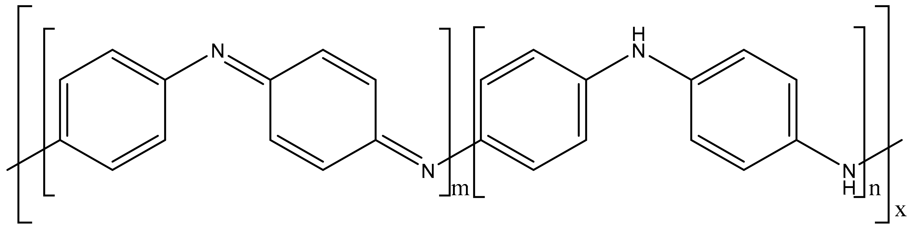
2.2. Preparation of Polyaniline
2.3. Polyaniline Characterisation
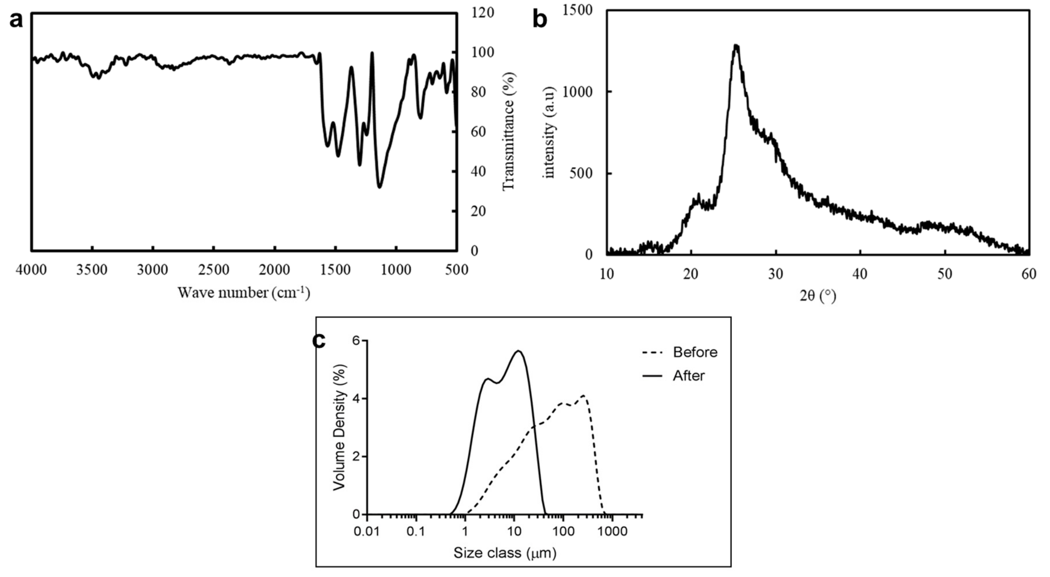
2.3.1. Fourier-Transform Infrared Spectroscopy
2.3.2. Powder X-ray Diffraction
2.3.3. Particle Size Characterisation
2.4. Fabrication of Polyaniline–Polycaprolactone Scaffolds
2.5. Scaffold Characterisation
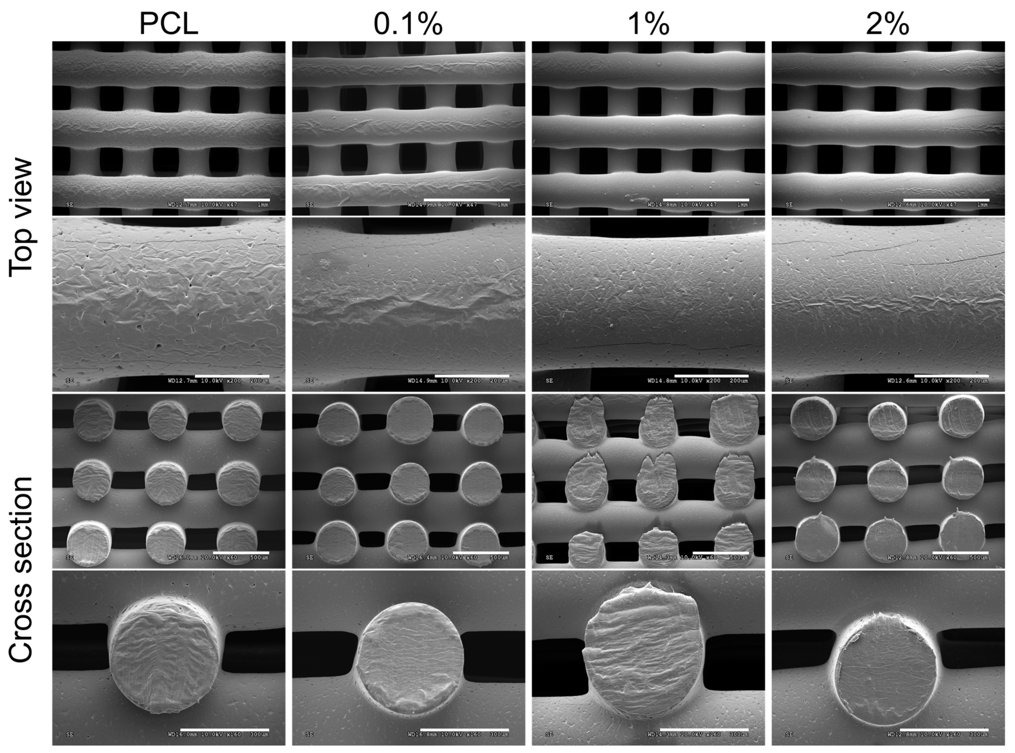
2.5.1. Morphology
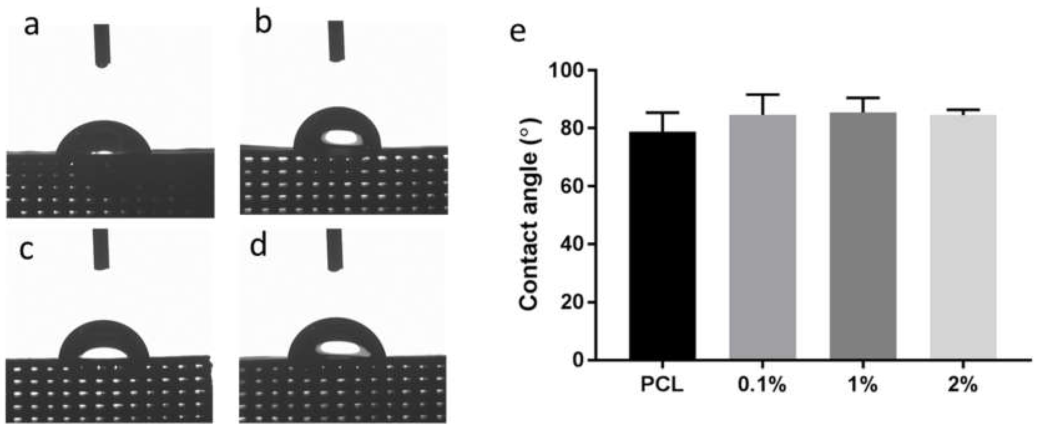
2.5.2. Wettability
2.5.3. Mechanical Properties
2.5.4. Conductivity
2.6. Biological Evaluation
2.6.1. Cell Culture and Seeding
2.6.2. Cell Viability
2.6.3. Cell Proliferation
2.7. Statistical Analysis
3. Results and Discussions
3.1. Characterisation of Polyaniline
3.2. Scaffold Characterisation
3.2.1. Scaffold Morphology
3.2.2. Wettability
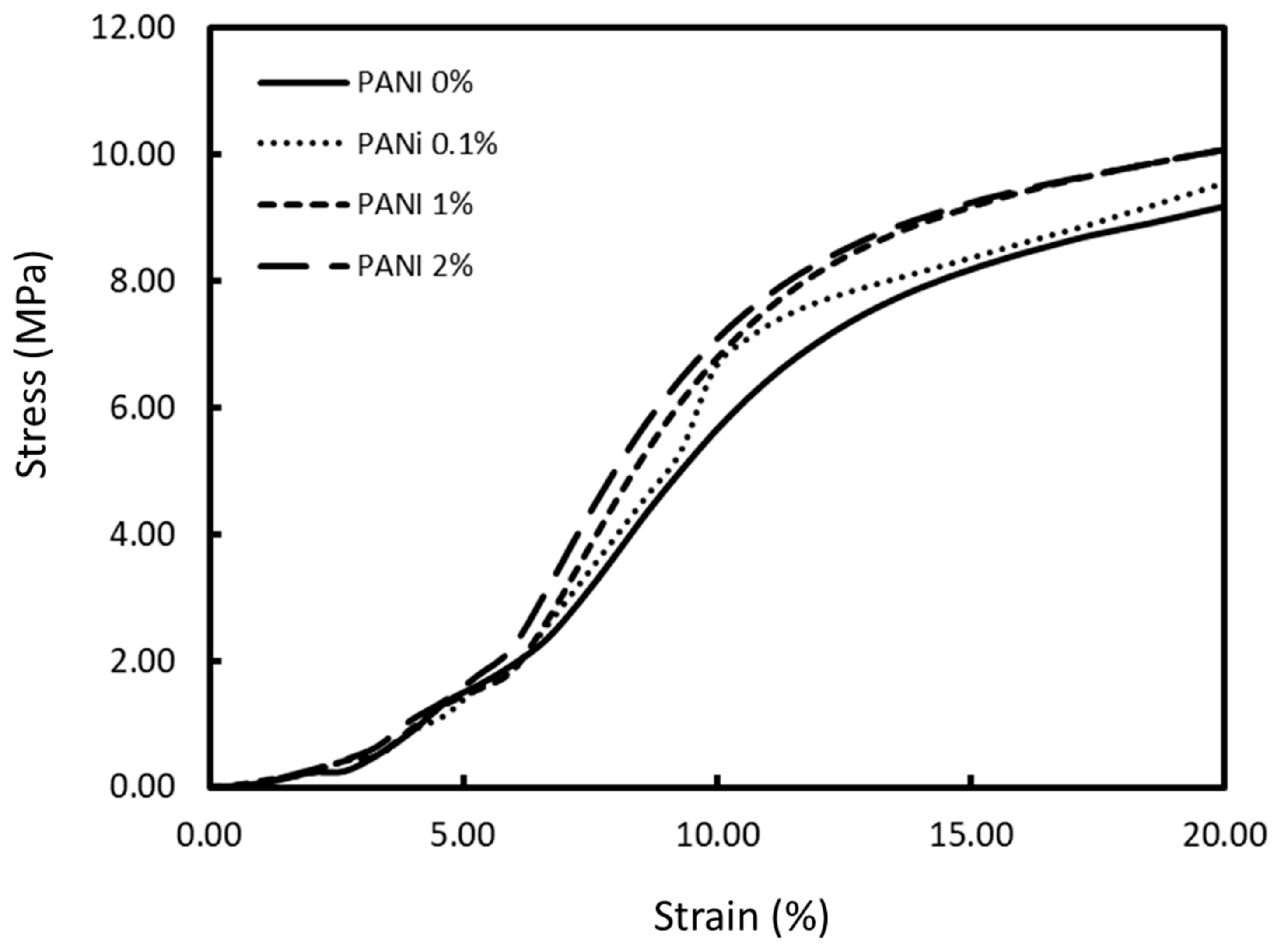
3.2.3. Mechanical Properties
3.2.4. Conductivity
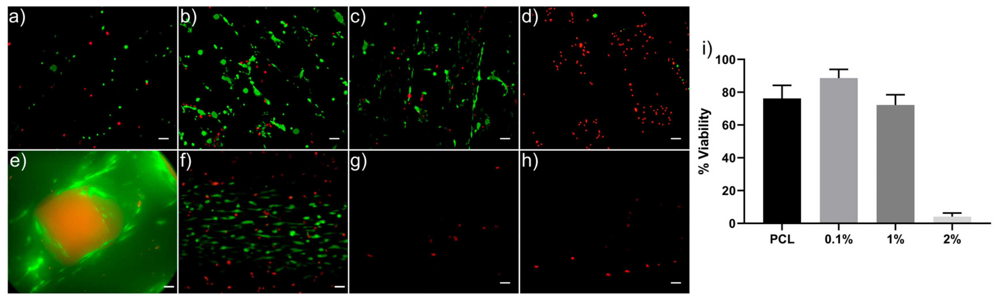
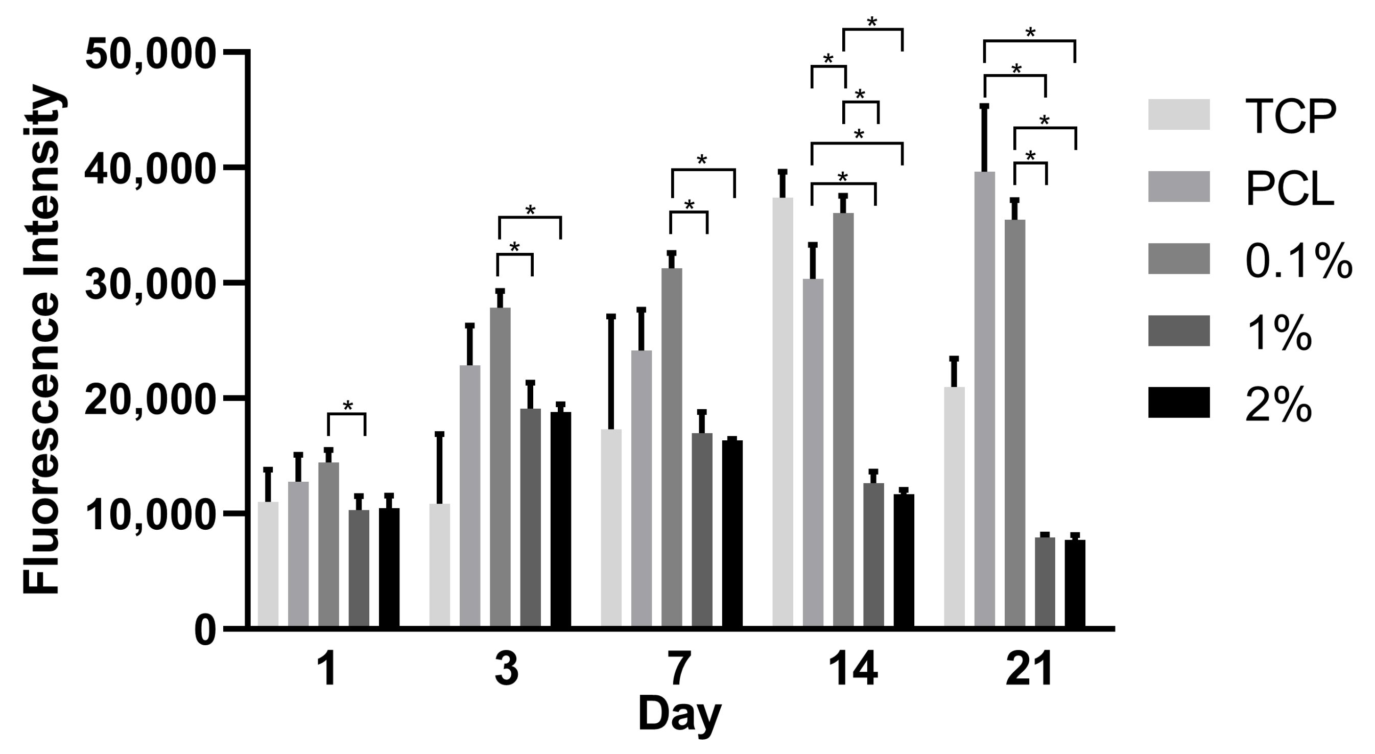
3.3. Cell Viability and Proliferation
4. Conclusions
Supplementary Materials
Author Contributions
Acknowledgments
Conflicts of Interest
References
- Hardy, J.G.; Lee, J.Y.; Schmidt, C.E. Biomimetic conducting polymer-based tissue scaffolds. Curr. Opin. Biotechnol. 2013, 24, 847–854. [Google Scholar] [CrossRef] [PubMed] [Green Version]
- Lee, J.Y. Electrically Conducting Polymer-Based Nanofibrous Scaffolds for Tissue Engineering Applications. Polym. Rev. 2013, 53, 443–459. [Google Scholar] [CrossRef]
- Balint, R.; Cassidy, N.J.; Cartmell, S.H. Conductive polymers: Towards a smart biomaterial for tissue engineering. Acta Biomater. 2014, 10, 2341–2353. [Google Scholar] [CrossRef] [PubMed]
- Ghasemi-Mobarakeh, L.; Prabhakaran, M.P.; Morshed, M.; Nasr-Esfahani, M.H.; Baharvand, H.; Kiani, S.; Al-Deyab, S.; Ramakrishna, S. Application of conductive polymers, scaffolds and electrical stimulation for nerve tissue engineering. J. Tissue Eng. Regen. Med. 2011, 5, e17–e35. [Google Scholar] [CrossRef] [PubMed]
- Zhang, Z.; Klausen, L.H.; Chen, M.; Dong, M. Electroactive Scaffolds for Neurogenesis and Myogenesis: Graphene-Based Nanomaterials. Small 2018, 14, 1801983. [Google Scholar] [CrossRef] [PubMed]
- Palza, H.; Zapata, A.P.; Angulo-Pineda, C. Electroactive Smart Polymers for Biomedical Applications. Materials 2019, 12, 277. [Google Scholar] [CrossRef] [PubMed] [Green Version]
- Guo, B.; Glavas, L.; Albertsson, A.-C. Biodegradable and electrically conducting polymers for biomedical applications. Prog. Polym. Sci. 2013, 38, 1263–1286. [Google Scholar] [CrossRef]
- Kaur, G.; Adhikari, R.; Cass, P.; Bown, M.; Gunatillake, P. Electrically conductive polymers and composites for biomedical applications. RSC Adv. 2015, 5, 37553–37567. [Google Scholar] [CrossRef]
- Sensharma, P.; Madhumathi, G.; Jayant, R.D.; Jaiswal, A.K. Biomaterials and cells for neural tissue engineering: Current choices. Mater. Sci. Eng. C 2017, 77, 1302–1315. [Google Scholar] [CrossRef]
- Chen, J.; Dong, R.; Ge, J.; Guo, B.; Ma, P.X. Biocompatible, Biodegradable, and Electroactive Polyurethane-Urea Elastomers with Tunable Hydrophilicity for Skeletal Muscle Tissue Engineering. ACS Appl. Mater. Interfaces 2015, 7, 28273–28285. [Google Scholar] [CrossRef]
- Chen, M.-C.; Sun, Y.-C.; Chen, Y.-H. Electrically conductive nanofibers with highly oriented structures and their potential application in skeletal muscle tissue engineering. Acta Biomater. 2013, 9, 5562–5572. [Google Scholar] [CrossRef] [PubMed]
- Wang, W.; Passarini, J.R., Jr.; Nalesso, P.R.L.; Musson, D.; Cornish, J.; Mendonça, F.; Caetano, G.F.; Bárrtolo, F. Engineered 3D printed poly(ɛ-caprolactone)/graphene scaffolds for bone tissue engineering. Mater. Sci. Eng. C 2019, 100, 759–770. [Google Scholar] [CrossRef] [PubMed]
- Wang, W.; Caetano, G.; Ambler, S.W.; Blaker, J.J.; Frade, A.M.; Mandal, P.; Diver, C.; Bártolo, P. Enhancing the Hydrophilicity and Cell Attachment of 3D Printed PCL/Graphene Scaffolds for Bone Tissue Engineering. Materials 2016, 9, 992. [Google Scholar] [CrossRef] [PubMed]
- Huang, B.; Vyas, C.; Roberts, I.; Poutrel, Q.-A.; Chiang, W.-H.; Blaker, J.J.; Huang, Z.; Bártolo, P. Fabrication and characterisation of 3D printed MWCNT composite porous scaffolds for bone regeneration. Mater. Sci. Eng. C 2019, 98, 266–278. [Google Scholar] [CrossRef]
- Martins, A.M.; Eng, G.; Caridade, S.G.; Mano, J.F.; Reis, R.L.; Vunjak-Novakovic, G. Electrically Conductive Chitosan/Carbon Scaffolds for Cardiac Tissue Engineering. Biomacromolecules 2014, 15, 635–643. [Google Scholar] [CrossRef]
- Wickham, A.; Vagin, M.; Khalaf, H.; Bertazzo, S.; Hodder, P.; Dånmark, S. Electroactive biomimetic collagen-silver nanowire composite scaffolds. Nanoscale 2016, 8, 14146–14155. [Google Scholar] [CrossRef] [Green Version]
- Baei, P.; Jalili-Firoozinezhad, S.; Rajabi-Zeleti, S.; Tafazzoli-Shadpour, M.; Baharvand, H.; Aghdami, N. Electrically conductive gold nanoparticle-chitosan thermosensitive hydrogels for cardiac tissue engineering. Mater. Sci. Eng. C 2016, 63, 131–141. [Google Scholar] [CrossRef]
- Nguyen, H.-L.; Jo, K.Y.; Cha, M.; Cha, J.Y.; Yoon, K.D.; Sanandiya, D.N.; Prajatelistia, E.; Oh, D.X.; Hwang, D.S. Mussel-Inspired Anisotropic Nanocellulose and Silver Nanoparticle Composite with Improved Mechanical Properties, Electrical Conductivity and Antibacterial Activity. Polymers 2016, 8, 102. [Google Scholar] [CrossRef] [Green Version]
- Aydemir Sezer, U.; Ozturk, K.; Aru, B.; Yanıkkaya Demirel, G.; Sezer, S.; Bozkurt, M.R. Zero valent zinc nanoparticles promote neuroglial cell proliferation: A biodegradable and conductive filler candidate for nerve regeneration. J. Mater. Sci. Mater. Med. 2016, 28, 19. [Google Scholar] [CrossRef]
- Baranes, K.; Shevach, M.; Shefi, O.; Dvir, T. Gold Nanoparticle-Decorated Scaffolds Promote Neuronal Differentiation and Maturation. Nano Lett. 2016, 16, 2916–2920. [Google Scholar] [CrossRef]
- Ravichandran, R.; Sridhar, R.; Venugopal, J.R.; Sundarrajan, S.; Mukherjee, S.; Ramakrishna, S. Gold Nanoparticle Loaded Hybrid Nanofibers for Cardiogenic Differentiation of Stem Cells for Infarcted Myocardium Regeneration. Macromol. Biosci. 2014, 14, 515–525. [Google Scholar] [CrossRef] [PubMed]
- Guimard, N.K.; Gomez, N.; Schmidt, C.E. Conducting polymers in biomedical engineering. Prog. Polym. Sci. 2007, 32, 876–921. [Google Scholar] [CrossRef]
- Guo, B.; Ma, P.X. Conducting Polymers for Tissue Engineering. Biomacromolecules 2018, 19, 1764–1782. [Google Scholar] [CrossRef] [PubMed]
- Gajendiran, M.; Choi, J.; Kim, S.-J.; Kim, K.; Shin, H.; Koo, H.-J.; Kim, K. Conductive biomaterials for tissue engineering applications. J. Ind. Eng. Chem. 2017, 51, 12–26. [Google Scholar] [CrossRef]
- Mattioli-Belmonte, M.; Giavaresi, G.; Biagini, G.; Virgili, L.; Giacomini, M.; Fini, M.; Giantomassi, F.; Natali, D.; Torricelli, P.; Giardino, R. Tailoring Biomaterial Compatibility: In Vivo Tissue Response versus in Vitro Cell Behavior. Int. J. Artif. Organs. 2003, 26, 1077–1085. [Google Scholar] [CrossRef] [PubMed]
- Bidez, P.R.; Li, S.; MacDiarmid, A.G.; Venancio, E.C.; Wei, Y.; Lelkes, P.I. Polyaniline, an electroactive polymer, supports adhesion and proliferation of cardiac myoblasts. J. Biomater. Sci. Polym. Ed. 2006, 17, 199–212. [Google Scholar] [CrossRef] [Green Version]
- Zarrintaj, P.; Rezaeian, I.; Bakhshandeh, B.; Heshmatian, B.; Ganjali, M.R. Bio—onductive Scaffold Based on Agarose—Polyaniline for Tissue Engineering. J. Skin Stem Cell 2017, 4, e67394. [Google Scholar]
- Ghasemi-Mobarakeh, L.; Prabhakaran, M.P.; Morshed, M.; Nasr-Esfahani, M.H.; Ramakrishna, S. Electrical Stimulation of Nerve Cells Using Conductive Nanofibrous Scaffolds for Nerve Tissue Engineering. Tissue Eng. Part A 2009, 15, 3605–3619. [Google Scholar] [CrossRef]
- Huang, L.; Zhuang, X.; Hu, J.; Lang, L.; Zhang, P.; Wang, Y.; Chen, X.; Wei, Y.; Jing, X. Synthesis of Biodegradable and Electroactive Multiblock Polylactide and Aniline Pentamer Copolymer for Tissue Engineering Applications. Biomacromolecules 2008, 9, 850–858. [Google Scholar] [CrossRef]
- Zhang, Q.-S.; Yan, Y.-H.; Li, S.-P.; Feng, T. Synthesis of a novel biodegradable and electroactive polyphosphazene for biomedical application. Biomed. Mater. 2009, 4, 035008. [Google Scholar] [CrossRef]
- Guo, Y.; Li, M.; Mylonakis, A.; Han, J.; MacDiarmid, A.G.; Chen, X.; Lelkes, P.I.; Wei, Y. Electroactive Oligoaniline-Containing Self-Assembled Monolayers for Tissue Engineering Applications. Biomacromolecules 2007, 8, 3025–3034. [Google Scholar] [CrossRef] [PubMed]
- Humpolicek, P.; Kasparkova, V.; Saha, P.; Stejskal, J. Biocompatibility of polyaniline. Synth. Met. 2012, 162, 722–727. [Google Scholar] [CrossRef]
- Cullen, D.K.; RPatel, A.; Doorish, J.F.; Smith, D.H.; Pfister, B.J. Developing a tissue-engineered neural-electrical relay using encapsulated neuronal constructs on conducting polymer fibers. J. Neural Eng. 2008, 5, 374–384. [Google Scholar] [CrossRef]
- Borriello, A.; Guarino, V.; Schiavo, L.; Alvarez-Perez, M.A.; Ambrosio, L. Optimizing PANi doped electroactive substrates as patches for the regeneration of cardiac muscle. J. Mater. Sci. Mater. Med. 2011, 22, 1053–1062. [Google Scholar] [CrossRef]
- Guarino, V.; Alvarez-Perez, M.A.; Borriello, A.; Napolitano, T.; Ambrosio, L. Conductive PANi/PEGDA Macroporous Hydrogels for Nerve Regeneration. Adv. Healthc. Mater. 2013, 2, 218–227. [Google Scholar] [CrossRef] [PubMed]
- Gizdavic-Nikolaidis, M.; Ray, S.; Bennett, J.R.; Easteal, A.J.; Cooney, R.P. Electrospun Functionalized Polyaniline Copolymer-Based Nanofibers with Potential Application in Tissue Engineering. Macromol. Biosci. 2010, 10, 1424–1431. [Google Scholar] [CrossRef]
- McKeon, K.D.; Lewis, A.; Freeman, J.W. Electrospun poly (D, L-lactide) and polyaniline scaffold characterisation. J. Appl. Polym. Sci. 2010, 115, 1566–1572. [Google Scholar] [CrossRef]
- Ostrovidov, S.; Ebrahimi, M.; Bae, H.; Nguyen, H.K.; Salehi, S.; Kim, S.B.; Kumatani, A.; Matsue, T.; Nakajima, K.; Hidema, S.; et al. Gelatin–Polyaniline Composite Nanofibers Enhanced Excitation–Contraction Coupling System Maturation in Myotubes. ACS Appl. Mater. Interfaces 2017, 9, 42444–42458. [Google Scholar] [CrossRef]
- Li, L.; Ge, J.; Guo, B.; Ma, P.X. In situ forming biodegradable electroactive hydrogels. Polym. Chem. 2014, 5, 2880–2890. [Google Scholar] [CrossRef]
- Li, L.; Ge, J.; Ma, P.X.; Guo, B. Injectable conducting interpenetrating polymer network hydrogels from gelatin-graft-polyaniline and oxidized dextran with enhanced mechanical properties. RSC Adv. 2015, 5, 92490–92498. [Google Scholar] [CrossRef]
- Chen, J.; Yu, M.; Guo, B.; Ma, P.X.; Yin, Z. Conductive nanofibrous composite scaffolds based on in-situ formed polyaniline nanoparticle and polylactide for bone regeneration. J. Colloid Interface Sci. 2018, 514, 517–527. [Google Scholar] [CrossRef] [PubMed]
- Ding, H.; Zhong, M.; Kim, Y.J.; Pholpabu, P.; Balasubramanian, A.; Hui, C.M.; He, H.; Yang, H.; Matyjaszewski, K.; Bettinger, C.J. Biologically Derived Soft Conducting Hydrogels Using Heparin-Doped Polymer Networks. ACS Nano 2014, 8, 4348–4357. [Google Scholar] [CrossRef] [PubMed]
- Dong, R.; Zhao, X.; Guo, B.; Ma, P.X. Self-Healing Conductive Injectable Hydrogels with Antibacterial Activity as Cell Delivery Carrier for Cardiac Cell Therapy. ACS Appl. Mater. Interfaces 2016, 8, 17138–17150. [Google Scholar] [CrossRef] [PubMed]
- Wang, L.; Wu, Y.; Guo, B.; Ma, P.X. Nanofiber Yarn/Hydrogel Core–Shell Scaffolds Mimicking Native Skeletal Muscle Tissue for Guiding 3D Myoblast Alignment, Elongation, and Differentiation. ACS Nano 2015, 9, 9167–9179. [Google Scholar] [CrossRef] [PubMed]
- Arioz, I.; Erol, O.; Bakan, G.; Dikecoglu, F.B.; Topal, A.E.; Urel, M.; Dana, A.; Tekinay, A.B.; Guler, M.O. Biocompatible Electroactive Tetra(aniline)-Conjugated Peptide Nanofibers for Neural Differentiation. ACS Appl. Mater. Interfaces 2018, 10, 308–317. [Google Scholar] [CrossRef] [PubMed] [Green Version]
- Guex, A.G.; Spicer, C.D.; Armgarth, A.; Gelmi, A.; Humphrey, E.J.; Terracciano, C.M.; Harding, S.E.; Stevens, M.M. Electrospun aniline-tetramer-co-polycaprolactone fibers for conductive, biodegradable scaffolds. Mrs Commun. 2017, 7, 375–382. [Google Scholar] [CrossRef] [Green Version]
- Vyas, C.; Poologasundarampillai, G.; Hoyland, J.; Bartolo, P. 12—3D printing of biocomposites for osteochondral tissue engineering. In Biomedical Composites, 2nd ed.; Ambrosio, L., Ed.; Woodhead Publishing: Cambridge, UK, 2017; pp. 261–302. [Google Scholar]
- Midha, S.; Dalela, M.; Sybil, D.; Patra, P.; Mohanty, S. Advances in three-dimensional bioprinting of bone: Progress and challenges. J. Tissue Eng. Regen. Med. 2019, 13, 925–945. [Google Scholar] [CrossRef]
- Vyas, C.; Pereira, R.; Huang, B.; Liu, F.; Wang, W.; Bartolo, P. Engineering the vasculature with additive manufacturing. Curr. Opin. Biomed. Eng. 2017, 2, 1–13. [Google Scholar] [CrossRef]
- Lee, S.-J.; Esworthy, T.; Stake, S.; Miao, S.; Zuo, Y.Y.; Harris, B.T. Advances in 3D Bioprinting for Neural Tissue Engineering. Adv. Biosyst. 2018, 2, 1700213. [Google Scholar] [CrossRef]
- Melchels, F.P.W.; Domingos, M.A.N.; Klein, T.J.; Malda, J.; Bartolo, P.J.; Hutmacher, D.W. Additive manufacturing of tissues and organs. Prog. Polym. Sci. 2012, 37, 1079–1104. [Google Scholar] [CrossRef] [Green Version]
- Stejskal, J.; Gilbert, R.G. Polyaniline. Preparation of a conducting polymer (IUPAC Technical Report). Pure Appl. Chem. 2002, 74, 857–867. [Google Scholar] [CrossRef] [Green Version]
- Abu-Thabit, N.Y. Chemical Oxidative Polymerization of Polyaniline: A Practical Approach for Preparation of Smart Conductive Textiles. J. Chem. Educ. 2016, 93, 1606–1611. [Google Scholar] [CrossRef]
- Wu, J.C.-C.; Ray, S.; Gizdavic-Nikolaidis, M.; Uy, B.; Swift, S.; Jin, J. Nanostructured bioactive material based on polycaprolactone and polyaniline fiber-scaffolds. Synth. Met. 2014, 198, 41–50. [Google Scholar] [CrossRef]
- Schindelin, J.; Arganda-Carreras, I.; Frise, E.; Kaynig, V.; Longair, M.; Pietzsch, T. Fiji: An open-source platform for biological-image analysis. Nat. Methods. 2012, 9, 676. [Google Scholar] [CrossRef] [PubMed] [Green Version]
- Domingos, M.; Intranuovo, F.; Russo, T.; De Santis, R.; Gloria, A.; Ambrosio, L. The first systematic analysis of 3D rapid prototyped poly(epsilon-caprolactone) scaffolds manufactured through BioCell printing: The effect of pore size and geometry on compressive mechanical behaviour and in vitro hMSC viability. Biofabrication 2013, 5, 045004. [Google Scholar] [CrossRef] [PubMed]
- Loh, Q.L.; Choong, C. Three-dimensional scaffolds for tissue engineering applications: Role of porosity and pore size. Tissue Eng. Part B Rev. 2013, 19, 485–502. [Google Scholar] [CrossRef] [Green Version]
- International Organization for Standardization. Rigid Cellular Plastics—Determination of Compression Properties; International Organization for Standardization, ISO: Geneva, Switzerland, 2014. [Google Scholar]
- Sobral, J.M.; Caridade, S.G.; Sousa, R.A.; Mano, J.F.; Reis, R.L. Three-dimensional plotted scaffolds with controlled pore size gradients: Effect of scaffold geometry on mechanical performance and cell seeding efficiency. Acta Biomater. 2011, 7, 1009–1018. [Google Scholar] [CrossRef] [Green Version]
- Zeng, F.; Qin, Z.; Liang, B.; Li, T.; Liu, N.; Zhu, M. Polyaniline nanostructures tuning with oxidants in interfacial polymerization system. Prog. Nat. Sci. Mater. Int. 2015, 25, 512–519. [Google Scholar] [CrossRef] [Green Version]
- Lee, K.; Cho, S.; Heum Park, S.; Heeger, A.J.; Lee, C.-W.; Lee, S.-H. Metallic transport in polyaniline. Nature 2006, 441, 65–68. [Google Scholar] [CrossRef]
- Zhou, H.H.; Wen, J.B.; Ning, X.H.; Fu, C.P.; Chen, J.H.; Kuang, Y.F. Comparison of the growth process and electrochemical properties of polyaniline films prepared by pulse potentiostatic and potentiostatic method on titanium electrode. J. Appl. Polym. Sci. 2007, 104, 458–463. [Google Scholar] [CrossRef]
- Murphy, C.M.; Haugh, M.G.; O’Brien, F.J. The effect of mean pore size on cell attachment, proliferation and migration in collagen–glycosaminoglycan scaffolds for bone tissue engineering. Biomaterials 2010, 31, 461–466. [Google Scholar] [CrossRef] [PubMed]
- O’Brien, F.J.; Harley, B.A.; Yannas, I.V.; Gibson, L.J. The effect of pore size on cell adhesion in collagen-GAG scaffolds. Biomaterials 2005, 26, 433–441. [Google Scholar] [CrossRef] [PubMed]
- Karageorgiou, V.; Kaplan, D. Porosity of 3D biomaterial scaffolds and osteogenesis. Biomaterials 2005, 26, 5474–5491. [Google Scholar] [CrossRef] [PubMed]
- Mitra, J.; Tripathi, G.; Sharma, A.; Basu, B. Scaffolds for bone tissue engineering: Role of surface patterning on osteoblast response. RSC Adv. 2013, 3, 11073–11094. [Google Scholar] [CrossRef]
- Boyan, B.D.; Lotz, E.M.; Schwartz, Z. Roughness and Hydrophilicity as Osteogenic Biomimetic Surface Properties. Tissue Eng. Part A 2017, 23, 1479–1489. [Google Scholar] [CrossRef]
- Menzies, K.L.; Jones, L. The impact of contact angle on the biocompatibility of biomaterials. Optom. Vis. Sci. 2010, 87, 387–399. [Google Scholar] [CrossRef]
- Deligöz, H. Preparation of self-standing polyaniline-based membranes: Doping effect on the selective ion separation and reverse osmosis properties. J. Appl. Polym. Sci. 2007, 105, 2640–2645. [Google Scholar] [CrossRef]
- Sarvari, R.; Akbari-Alanjaraghi, M.; Massoumi, B.; Beygi-Khosrowshahi, Y.; Agbolaghi, S. Conductive and biodegradable scaffolds based on a five-arm and functionalized star-like polyaniline–polycaprolactone copolymer with a d-glucose core. New J. Chem. 2017, 41, 6371–6384. [Google Scholar] [CrossRef]
- Huang, B.; Bartolo, P.J. Rheological Characterisation of Polymer/ceramic blends for 3D printing of bone scaffolds. Polym. Test. 2018, 68, 365–378. [Google Scholar] [CrossRef] [Green Version]
- Rosales-Leal, J.I.; Rodríguez-Valverde, M.A.; Mazzaglia, G.; Ramón-Torregrosa, P.J.; Díaz-Rodríguez, L.; García-Martínez, O.; Vallecillo-Capilla, M.; Ruiz, C.; Cabrerizo-Vílchez, M.A. Effect of roughness, wettability and morphology of engineered titanium surfaces on osteoblast-like cell adhesion. Colloids Surf. A Physicochem. Eng. Asp. 2010, 365, 222–229. [Google Scholar] [CrossRef]
- Gibson, L.J. Biomechanics of cellular solids. J. Biomech. 2005, 38, 377–399. [Google Scholar] [CrossRef] [PubMed]
- Martin, R.B.; Burr, D.B.; Sharkey, N.A.; Fyhrie, D.P. Mechanical Properties of Bone. In Skeletal Tissue Mechanics; Martin, R.B., Burr, D.B., Sharkey, N.A., Fyhrie, D.P., Eds.; Springer: New York, NY, USA, 2015; pp. 355–422. [Google Scholar]
- Oftadeh, R.; Perez-Viloria, M.; Villa-Camacho, J.C.; Vaziri, A.; Nazarian, A. Biomechanics and Mechanobiology of Trabecular Bone: A Review. J. Biomech. Eng. 2015, 137, 010802. [Google Scholar] [CrossRef] [PubMed] [Green Version]
- Saha, S.; Williams, P.A. Comparison of the electrical and dielectric behavior of wet human cortical and cancellous bone tissue from the distal tibia. J. Orthop. Res. 1995, 13, 524–532. [Google Scholar] [CrossRef] [PubMed]
- Mahat, M.M.; Mawad, D.; Nelson, G.W.; Fearn, S.; Palgrave, R.G.; Payne, D.J.; Stevens, M.M. Elucidating the deprotonation of polyaniline films by X-ray photoelectron spectroscopy. J. Mater. Chem. C 2015, 3, 7180–7186. [Google Scholar] [CrossRef]
- Li, Y.; Li, X.; Zhao, R.; Wang, C.; Qiu, F.; Sun, B.; Ji, H.; Qiu, J.; Wang, C. Enhanced adhesion and proliferation of human umbilical vein endothelial cells on conductive PANI-PCL fiber scaffold by electrical stimulation. Mater. Sci. Eng. C 2017, 72, 106–112. [Google Scholar] [CrossRef]


| Volume Distribution | Size (µm) | |
|---|---|---|
| Before | After | |
| Dx (10) | 6.57 ± 0.142 | 1.66 ± 0.004 |
| Dx (50) | 62.4 ± 3.3 | 6.47 ± 0.06 |
| Dx (90) | 306 ± 37 | 20.5 ± 0.1 |
| PANI Concentration (% wt.) | Fibre Diameter (µm) | Pore Size (µm) | Porosity (%) |
|---|---|---|---|
| 0 | 379.1 ± 24.1 | 314.6 ± 23.8 | 49.51 ± 0.740 |
| 0.1 | 364.8 ± 22.9 | 305.9 ± 35.5 | 48.16 ± 1.071 |
| 1 | 379.3 ± 21.2 | 295.5 ± 34.5 | 48.01 ± 0.457 |
| 2 | 382.5 ± 22.2 | 290.9 ± 28.6 | 44.69 ± 1.602 |
| PANI Concentration (% wt.) | Compressive Young’s Modulus (MPa) | Compressive Strength (MPa) |
|---|---|---|
| 0 | 64.43 ± 3.97 | 5.53 ± 0.08 |
| 0.1 | 68.35 ± 5.15 | 6.45 ± 0.16 |
| 1 | 73.83 ± 4.22 | 6.83 ± 0.10 |
| 2 | 82.61 ± 6.94 | 7.38 ± 0.35 |
| PANI Concentration (% wt.) | Conductivity (10−4 S/cm) |
|---|---|
| 0.1 | 2.46 ± 0.85 |
| 1 | 2.53 ± 0.65 |
| 2 | 2.84 ± 0.51 |
© 2020 by the authors. Licensee MDPI, Basel, Switzerland. This article is an open access article distributed under the terms and conditions of the Creative Commons Attribution (CC BY) license (http://creativecommons.org/licenses/by/4.0/).
Share and Cite
Wibowo, A.; Vyas, C.; Cooper, G.; Qulub, F.; Suratman, R.; Mahyuddin, A.I.; Dirgantara, T.; Bartolo, P. 3D Printing of Polycaprolactone–Polyaniline Electroactive Scaffolds for Bone Tissue Engineering. Materials 2020, 13, 512. https://doi.org/10.3390/ma13030512
Wibowo A, Vyas C, Cooper G, Qulub F, Suratman R, Mahyuddin AI, Dirgantara T, Bartolo P. 3D Printing of Polycaprolactone–Polyaniline Electroactive Scaffolds for Bone Tissue Engineering. Materials. 2020; 13(3):512. https://doi.org/10.3390/ma13030512
Chicago/Turabian StyleWibowo, Arie, Cian Vyas, Glen Cooper, Fitriyatul Qulub, Rochim Suratman, Andi Isra Mahyuddin, Tatacipta Dirgantara, and Paulo Bartolo. 2020. "3D Printing of Polycaprolactone–Polyaniline Electroactive Scaffolds for Bone Tissue Engineering" Materials 13, no. 3: 512. https://doi.org/10.3390/ma13030512