The Effect of Viscosity-Modifying Admixture on the Extrudability of Limestone and Calcined Clay-Based Cementitious Material for Extrusion-Based 3D Concrete Printing

 , , , ,
Abstract
:1. Introduction
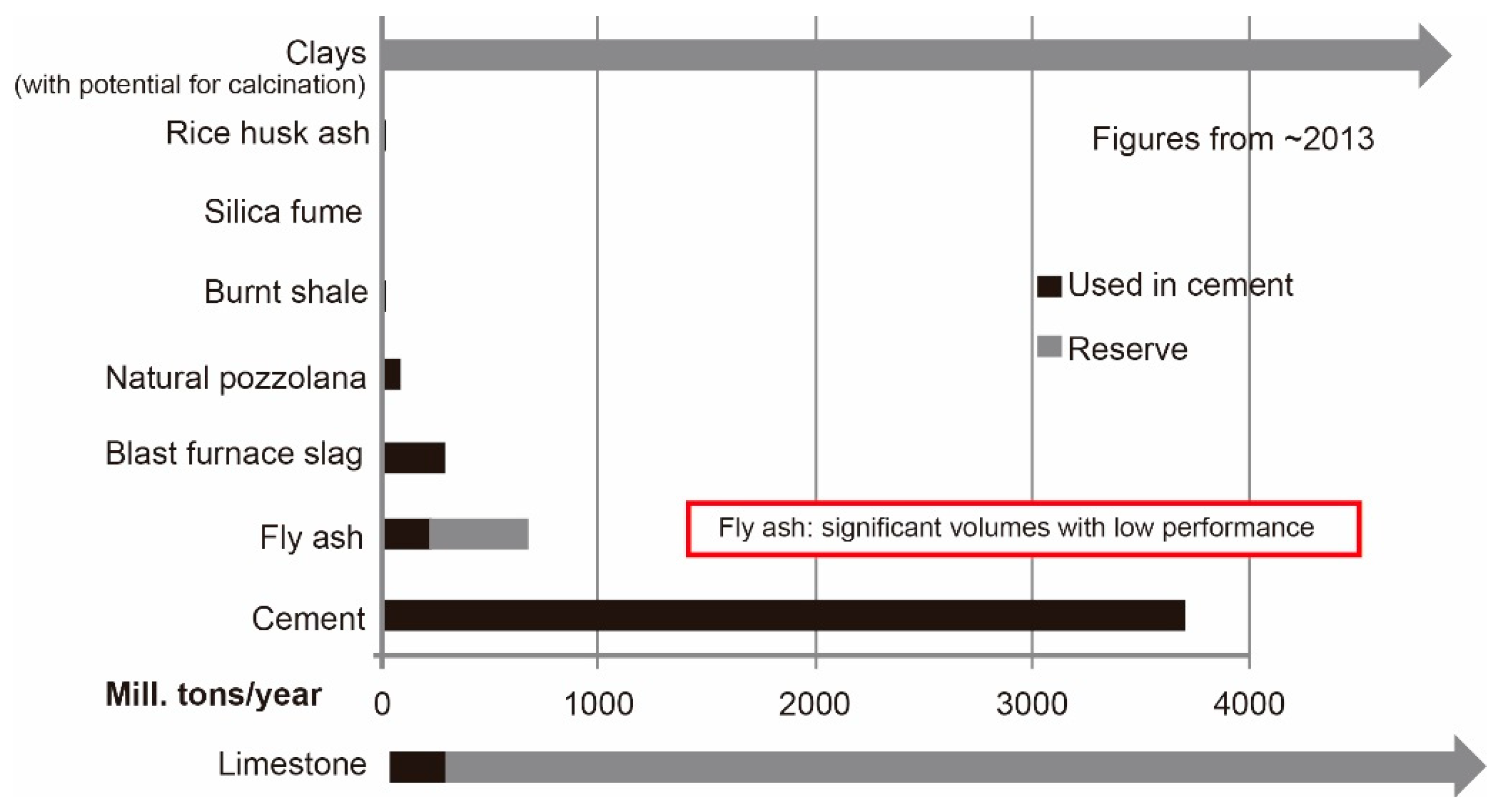
- Clays are abundant materials throughout the world. The available amount of clay is much higher than other common supplementary cementing materials (SCMs), such as fly ash, silica fume, and slag (see Figure 1).
- The heating temperature for making calcined clay (700–850 °C) is much lower than for the clinker. A relatively lower amount of CO2 is emitted during the producing process of calcined clay, compared with the clinker [19].
- Good, early-age mechanical performance of hardened concrete could be achieved, even by using low-grade calcined clay (contained at least 40% of metakaolin). Up to 50% of the clinker in the binder could be replaced by limestone and low-grade calcined clay, with a comparable compressive strength after 7 days [17].
- Comparable durability (good resistance to chloride penetration and sulfates attack) [16].
2. Materials and Methods
2.1. Material and Mix Design
- Homogenize the dry components by a planetary mixer (HOBART N50, HOBART, Offenburg, Baden-Württemberg, Germany), for 4 min at a low speed (60 rpm).
- Add the water-based solution (water and superplasticizer) while mixing at a low speed.
- After 2.5 min, pause, scrape the walls and blade (a dough-like mixture is generated).
- Mix the mixture again at a higher speed (124 rpm) for 1.5 min.
- Stop, start to fill the barrel.
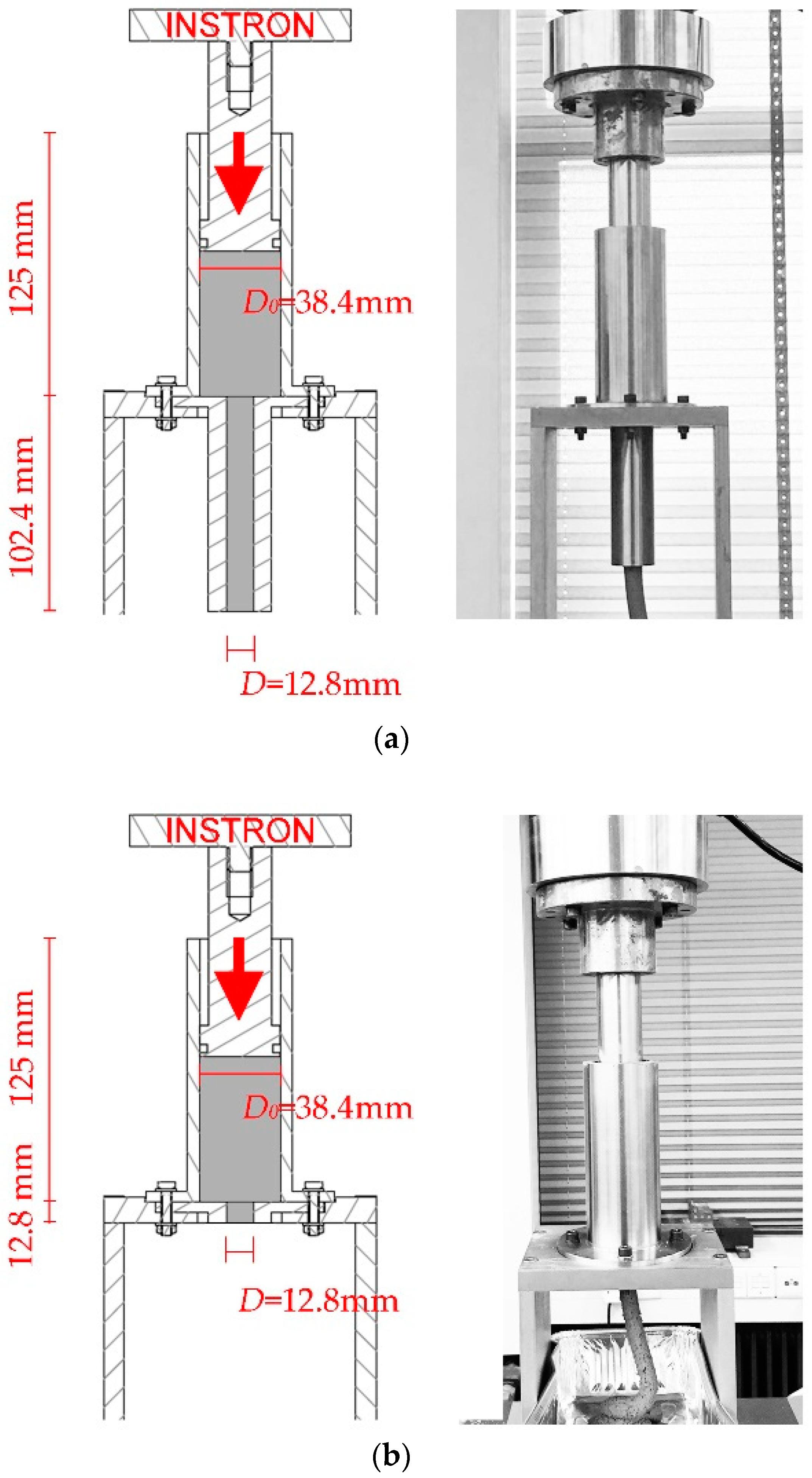
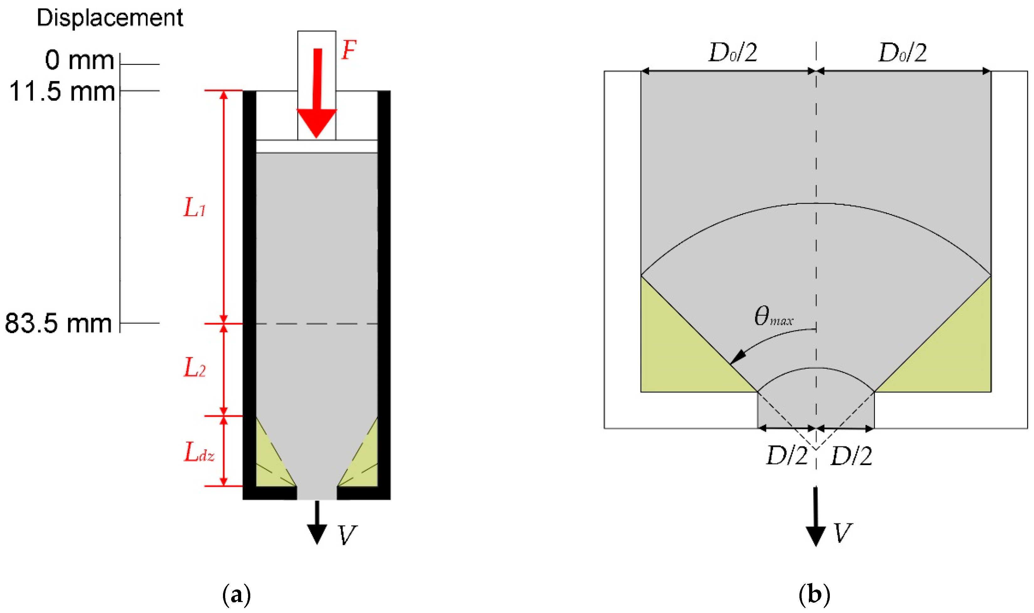
2.2. Ram Extruder and Test Procedure
2.2.1. Ram Extruder
2.2.2. Extrusion Pressures with Different Ages
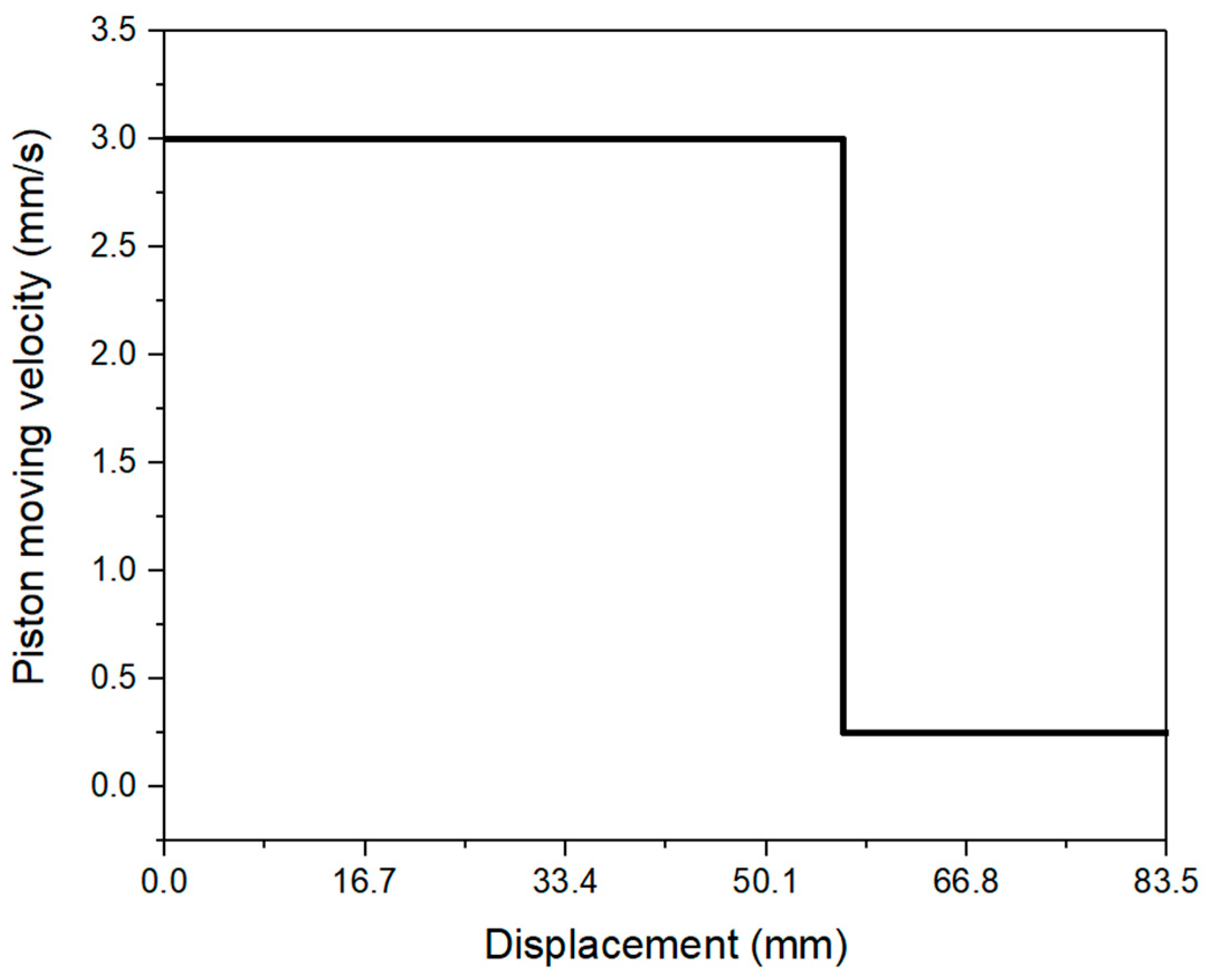
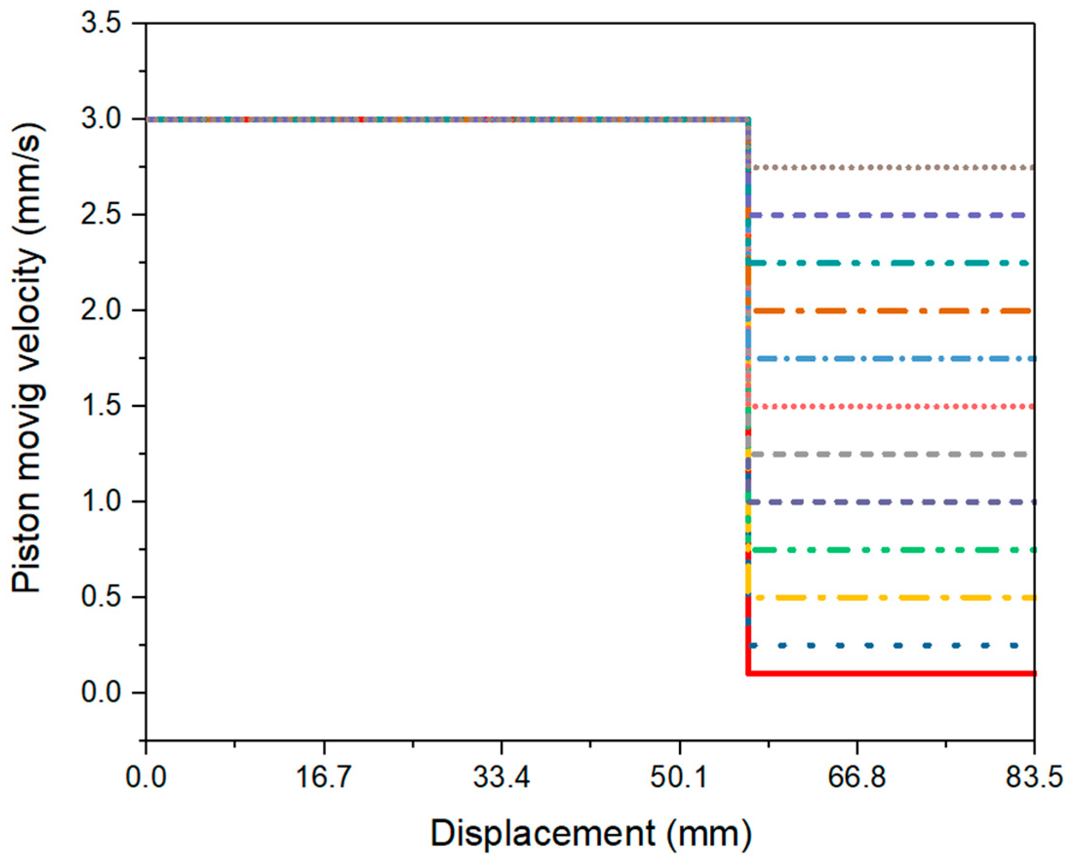
2.2.3. Extrusion Pressures with Different Material Flow Rates
3. Results and Discussion
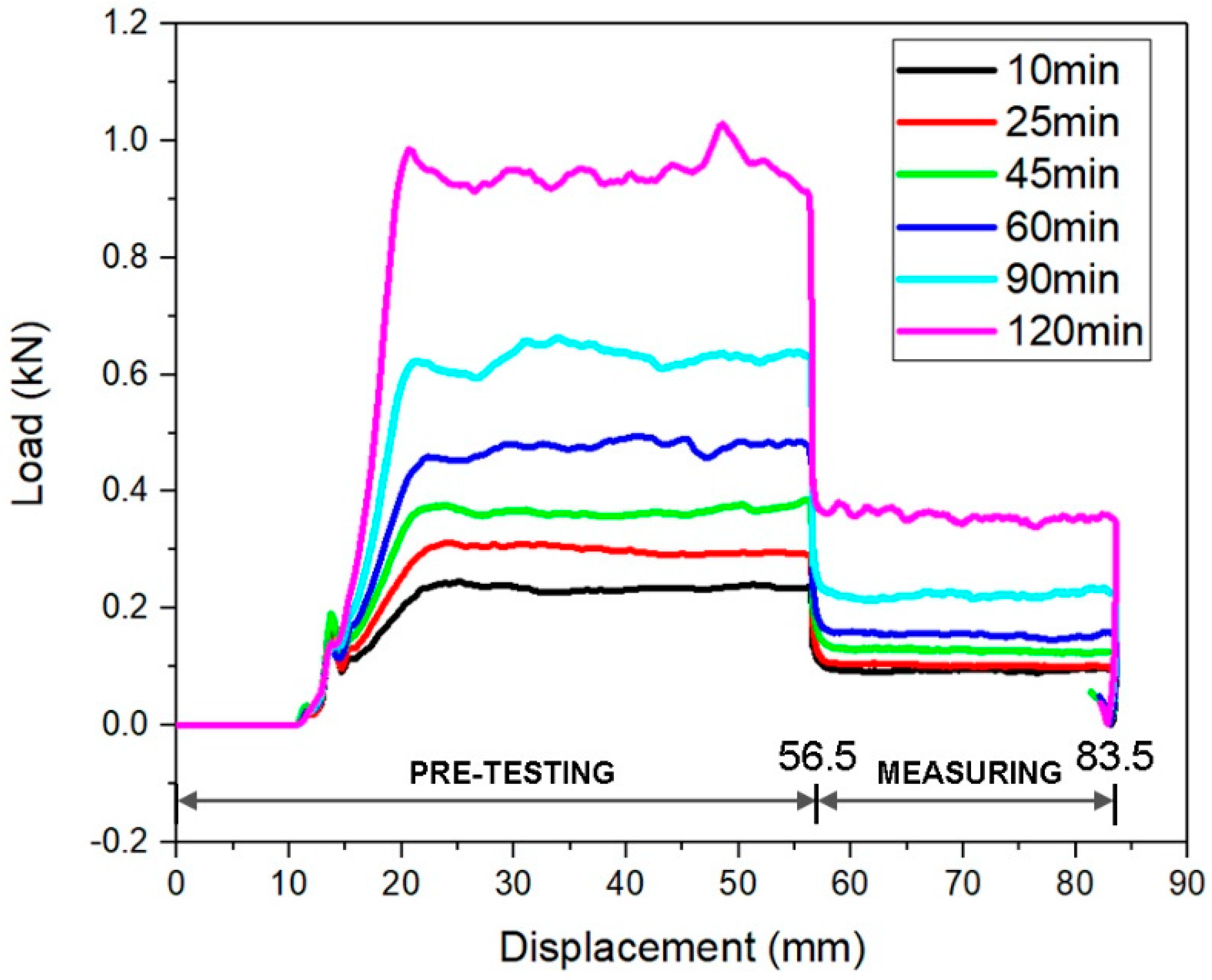
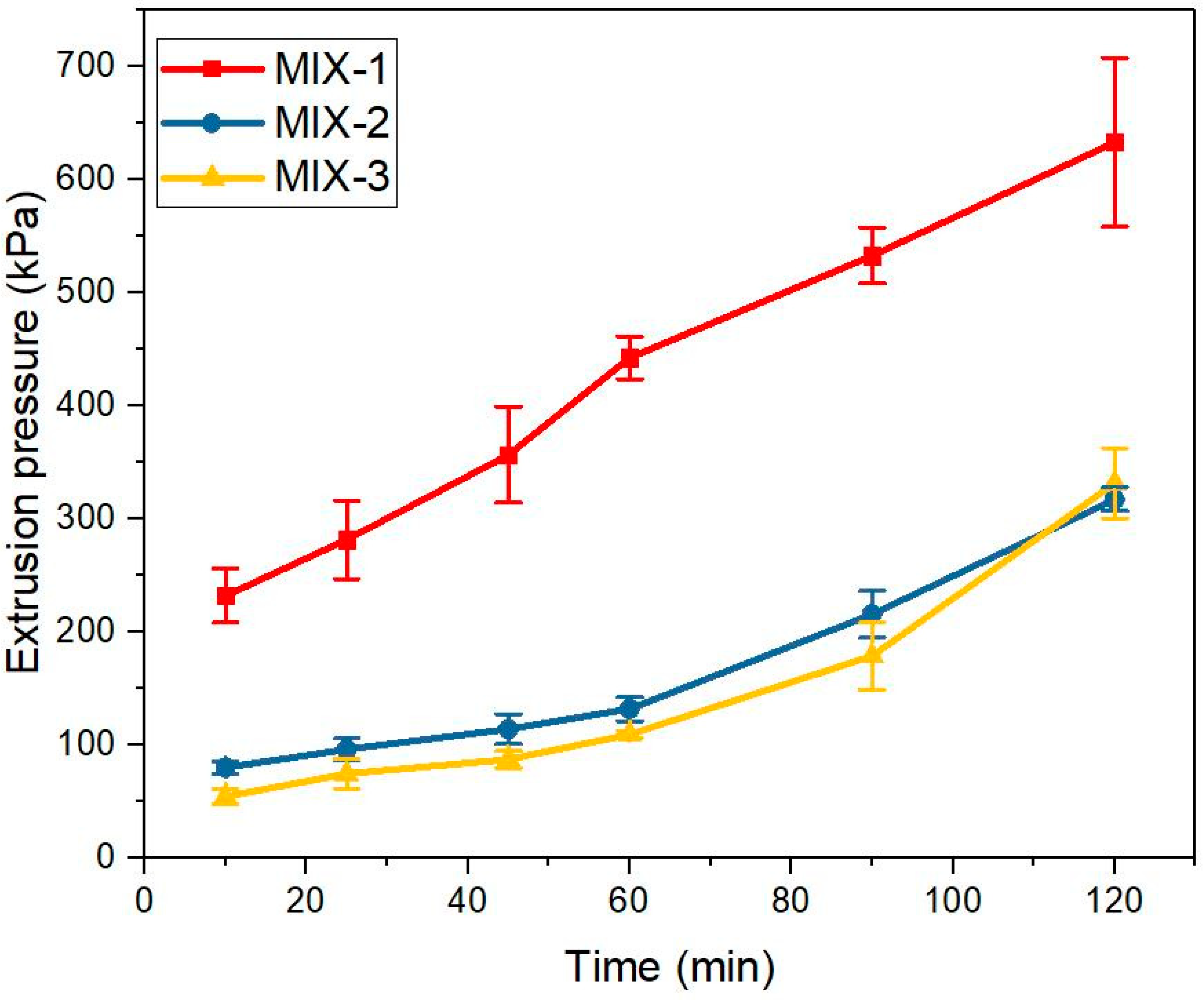
3.1. Extrusion Pressures with Different Ages
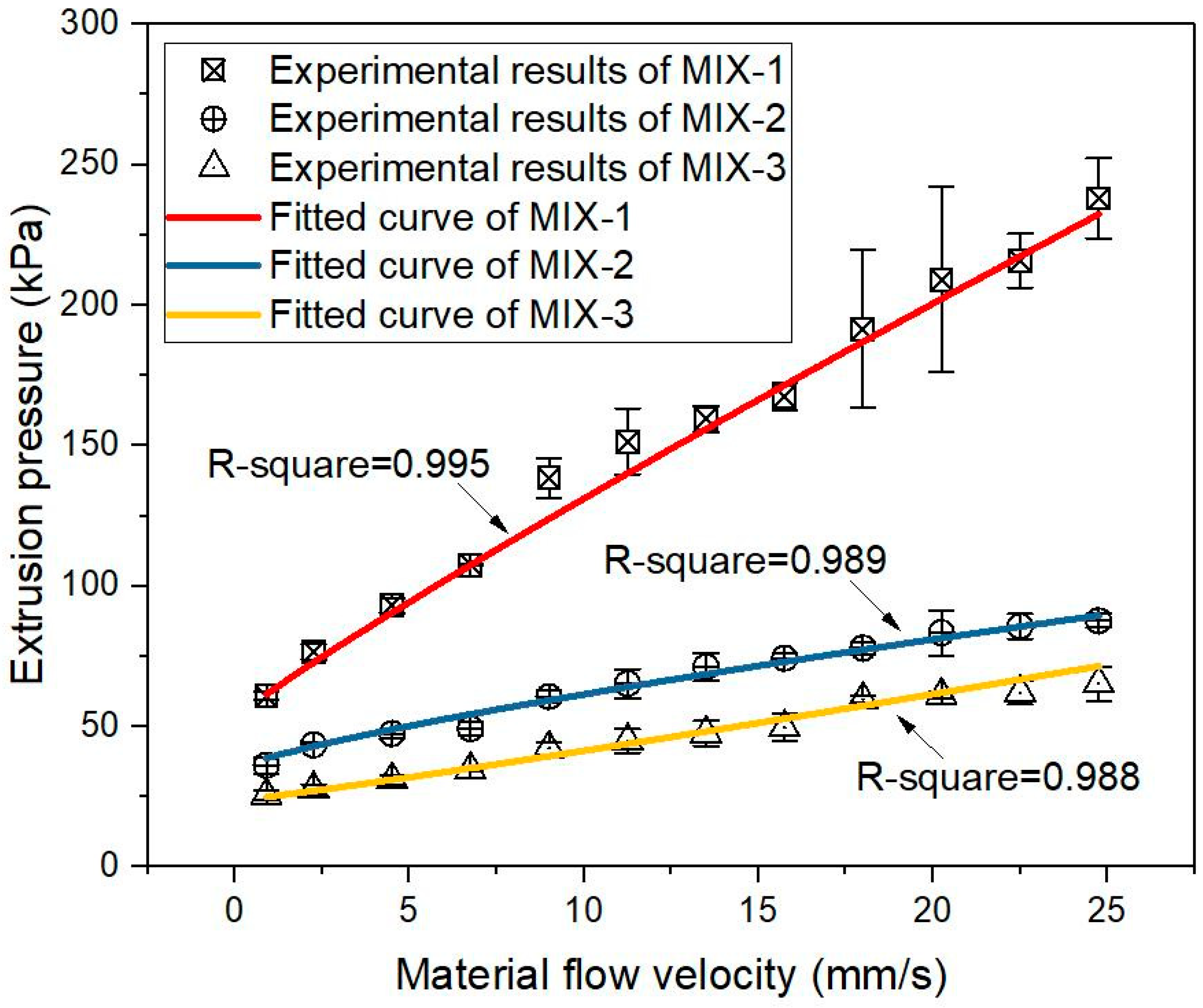
3.2. Extrusion Pressures with Different Material Flow Rates
4. Conclusions
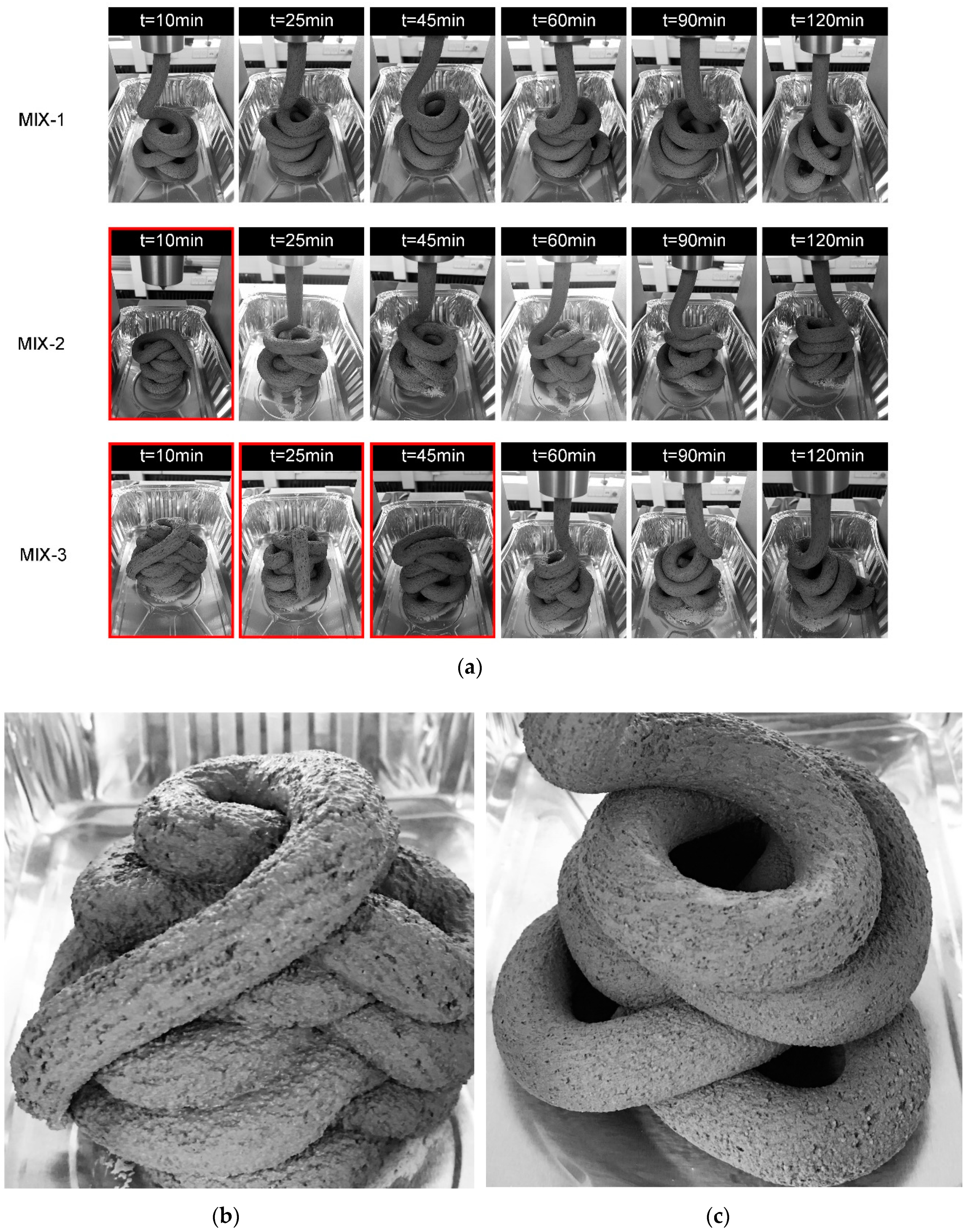
- The extrusion pressure of all mix designs exhibited an increasing trend with time. At the same tested age, the extrusion pressure (under 0.25 mm/s of piston speed) was increased by increasing the dosage of VMA. The shape retention of extruded filaments was enhanced as well. MIX-1 had a better cohesion at all tested ages. For mixtures MIX-2 and MIX-3, a good shape stability was found after the age of 25 min and 60 min, respectively.
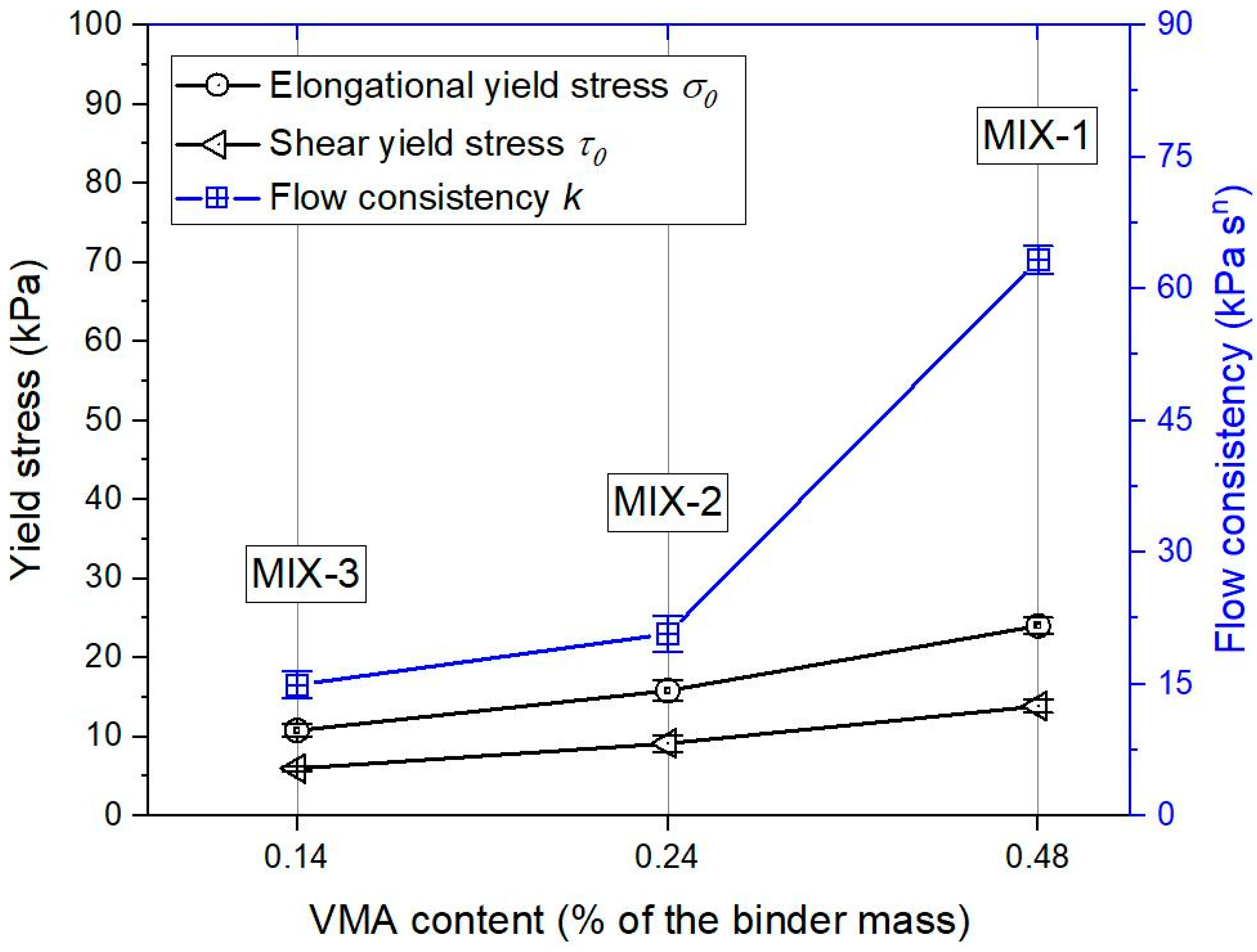
- Under the same extrusion rates at the age of 10 min, the mixture with higher VMA contents showed higher extrusion pressures. The correlation between experimental results and Basterfield et al. model was excellent (R-squared: 0.99). Increasing the dosage of VMA from 0.14% to 0.48% could increase the elongational yield stress σ0, the flow consistency k, and the shear yield stress τ0.
- Among all mix designs in this study, MIX-2 might be the most suitable mix design for extrusion-based 3DCP. It not only had relatively small extrusion pressures at different ages or under different extrusion rates, but showed a good shape stability since the age of 25 min.
- The differences between the ram extrusion and screw extrusion have been illustrated by Perrot et al. [27]. Most of the pumps for 3DCP are based on screw extrusions. It is essential to evaluate the extrudability of mixtures MIX-1, MIX-2, and MIX-3, by a screw extrusion pump. The correlation between the ram extruder and the screw extrusion pump needs to be investigated.
- Buildability is also an important constraint for developing 3D printable cementitious materials. Since the HPMC-based VMA could retard the initial setting time and hydration of cement, the early-age strength development might have been affected by using a higher dosage of VMA in the mixtures. Thus, the effects of VMA on early-age strength development of mixtures MIX-1, MIX-2, and MIX-3 are worth to be explored.
Author Contributions
Funding
Acknowledgments
Conflicts of Interest
References
- Buswell, R.; De Silva, W.L.; Jones, S.; Dirrenberger, J. 3D printing using concrete extrusion: A roadmap for research. Cem. Concr. Res. 2018, 112, 37–49. [Google Scholar] [CrossRef]
- Cesaretti, G.; Dini, E.; De Kestelier, X.; Colla, V.; Pambaguian, L. Building components for an outpost on the Lunar soil by means of a novel 3D printing technology. Acta Astronaut. 2014, 93, 430–450. [Google Scholar] [CrossRef]
- Naser, M.Z.; Chehab, A.I. Materials and design concepts for space-resilient structures. Prog. Aerosp. Sci. 2018, 98, 74–90. [Google Scholar] [CrossRef]
- Evans, M.A.; Campbell, R.I. A comparative evaluation of industrial design models produced using rapid prototyping and workshop-based fabrication techniques. Rapid Prototyp. J. 2003, 9, 344–351. [Google Scholar] [CrossRef]
- Lim, S.; Buswell, R.A.; Valentine, P.J.; Piker, D.; Austin, S.A.; De Kestelier, X. Modelling curved-layered printing paths for fabricating large-scale construction components. Addit. Manuf. 2016, 12, 216–230. [Google Scholar] [CrossRef] [Green Version]
- Figueiredo, S.C.; Rodrıguez, C.R.; Ahmed, Z.Y.; Bos, D.H.; Xu, Y.; Salet, T.A.M.; Copuroglu, O.; Schlangen, E.; Bos, F.P. An approach to develop printable strain hardening cementitious composites. Mater. Des. 2019, 169, 107651. [Google Scholar] [CrossRef]
- Bos, F.P.; Ahmed, Z.Y.; Jutinov, E.R.; Salet, T.A.M. Experimental Exploration of Metal Cable as Reinforcement in 3D Printed Concrete. Materials 2017, 10, 1314. [Google Scholar] [CrossRef] [PubMed]
- Ogura, H.; Nerella, V.N.; Mechtcherine, V. Developing and Testing of Strain-Hardening Cement-Based Composites (SHCC) in the Context of 3D-Printing. Materials 2018, 11, 1375. [Google Scholar] [CrossRef]
- Reiter, L.; Wangler, T.; Roussel, N.; Flatt, R.J. The role of early age structural build-up in digital fabrication with concrete. Cem. Concr. Res. 2018, 112, 86–95. [Google Scholar] [CrossRef]
- Jeong, H.; Han, S.-J.; Choi, S.-H.; Lee, Y.J.; Yi, S.T.; Kim, K.S. Rheological Property Criteria for Buildable 3D Printing Concrete. Materials 2019, 12, 657. [Google Scholar] [CrossRef] [PubMed]
- Bos, F.; Wolfs, R.; Ahmed, Z.; Salet, T. Additive manufacturing of concrete in construction: Potentials and challenges of 3D concrete printing. Virtual Phys. Prototyp. 2016, 11, 1–17. [Google Scholar] [CrossRef]
- Weng, Y.; Li, M.; Tan, M.J.; Qian, S. Design 3D printing cementitious materials via Fuller Thompson theory and Marson-Percy model. Constr. Mater. 2018, 163, 600–610. [Google Scholar] [CrossRef]
- Panda, B.; Unluer, C.; Tan, M.J. Investigation of the rheology and strength of geopolymer mixtures for extrusion-based 3D printing. Cem. Concr. Compos. 2018, 94, 307–314. [Google Scholar] [CrossRef]
- Chen, Y.; Veer, F.; Copuroglu, O.; Schlangen, E. Feasibility of Using Low CO2 Concrete Alternatives in Extrusion-Based 3D Concrete Printing. In Proceedings of the RILEM Bookseries; Springer Nature: Zurich, Switzerland, 2018; pp. 269–276. [Google Scholar]
- Chen, Y.; Veer, F.; Copuroglu, O. A Critical Review of 3D Concrete Printing as a Low CO2 Concrete Approach. Heron 2017, 62, 167–194. [Google Scholar]
- Scrivener, K.; Martirena, F.; Bishnoi, S.; Maity, S. Calcined clay limestone cements (LC3). Cem. Concr. Res. 2018, 114, 49–56. [Google Scholar] [CrossRef]
- Avet, F.; Snellings, R.; Diaz, A.A.; Ben Haha, M.; Scrivener, K. Development of a new rapid, relevant and reliable (R3) test method to evaluate the pozzolanic reactivity of calcined kaolinitic clays. Cem. Concr. Res. 2016, 85, 1–11. [Google Scholar] [CrossRef]
- Antoni, M.; Rossen, J.; Martirena, F.; Scrivener, K. Cement substitution by a combination of metakaolin and limestone. Cem. Concr. Res. 2012, 42, 1579–1589. [Google Scholar] [CrossRef]
- Huang, W.; Kazemi-Kamyab, H.; Sun, W.; Scrivener, K. Effect of replacement of silica fume with calcined clay on the hydration and microstructural development of eco-UHPFRC. Mater. Des. 2017, 121, 36–46. [Google Scholar] [CrossRef]
- Perrot, A.; Rangeard, D.; Pierre, A. Structural built-up of cement-based materials used for 3D-printing extrusion techniques. Mater. Struct. 2016, 49, 1213–1220. [Google Scholar] [CrossRef]
- Roussel, N. Rheological requirements for printable concretes. Cem. Concr. Res. 2018, 112, 76–85. [Google Scholar] [CrossRef]
- Ma, B.; Peng, Y.; Tan, H.; Jian, S.; Zhi, Z.; Guo, Y.; Qi, H.; Zhang, T.; He, X. Effect of hydroxypropyl-methyl cellulose ether on rheology of cement paste plasticized by polycarboxylate superplasticizer. Constr. Mater. 2018, 160, 341–350. [Google Scholar] [CrossRef]
- Chaves Figueiredo, S.; Çopuroğlu, O.; Schlangen, E. Effect of viscosity modifier admixture on Portland cement paste hydration and microstructure. Constr. Build. Mater. 2019, 212, 818–840. [Google Scholar] [CrossRef]
- Ou, Z.H.; Ma, B.G.; Jian, S.W. Influence of cellulose ethers molecular parameters on hydration kinetics of Portland cement at early ages. Constr. Mater. 2012, 33, 78–83. [Google Scholar] [CrossRef]
- Ding, Z.; Wang, X.; Sanjayan, J.; Zou, P.X.; Ding, Z.-K. A Feasibility Study on HPMC-Improved Sulphoaluminate Cement for 3D Printing. Materials 2018, 11, 2415. [Google Scholar] [CrossRef] [PubMed]
- Zhou, X.; Li, Z.; Fan, M.; Chen, H. Rheology of semi-solid fresh cement pastes and mortars in orifice extrusion. Cem. Concr. Compos. 2013, 37, 304–311. [Google Scholar] [CrossRef] [Green Version]
- Perrot, A.; Rangeard, D.; Nerella, V.; Mechtcherine, V. Extrusion of cement-based materials - an overview. RILEM Tech. Lett. 2019, 3, 91–97. [Google Scholar] [CrossRef]
- Nerella, V.; Näther, M.; Iqbal, A.; Butler, M.; Mechtcherine, V. Inline quantification of extrudability of cementitious materials for digital construction. Cem. Concr. Compos. 2019, 95, 260–270. [Google Scholar] [CrossRef]
- Benbow, J.; Oxley, E.; Bridgwater, J. The extrusion mechanics of pastes—the influence of paste formulation on extrusion parameters. Chem. Eng. Sci. 1987, 42, 2151–2162. [Google Scholar] [CrossRef]
- Basterfield, R.; Lawrence, C.; Adams, M. On the interpretation of orifice extrusion data for viscoplastic materials. Chem. Eng. Sci. 2005, 60, 2599–2607. [Google Scholar] [CrossRef]
- Perrot, A.; Mélinge, Y.; Rangeard, D.; Micaelli, F.; Estellé, P.; Lanos, C. Use of ram extruder as a combined rheo-tribometer to study the behaviour of high yield stress fluids at low strain rate. Rheol. Acta 2012, 51, 743–754. [Google Scholar] [CrossRef] [Green Version]
- Chen, Y.; Li, Z.; Figueiredo, S.C.; Copuroglu, O.; Veer, F.; Schlangen, E. Limestone and Calcined Clay-based Sustainable Cementitious Materials for 3D Concrete Printing A Fundamental Study of Extrudability and Early-age Strength Development. Appl. Sci. 2019. accepted for publication. [Google Scholar]
- Ma, G.; Sun, J.; Wang, L.; Aslani, F.; Liu, M. Electromagnetic and microwave absorbing properties of cementitious composite for 3D printing containing waste copper solids. Cem. Concr. Compos. 2018, 94, 215–225. [Google Scholar] [CrossRef]
- Benbow, J.; Bridgwater, J. The influence of formulation on extrudate structure and strength. Chem. Eng. Sci. 1987, 42, 753–766. [Google Scholar] [CrossRef]
- Marchon, D.; Kawashima, S.; Bessaies-Bey, H.; Mantellato, S.; Ng, S. Hydration and rheology control of concrete for digital fabrication: Potential admixtures and cement chemistry. Cem. Concr. Res. 2018, 112, 96–110. [Google Scholar] [CrossRef]
- Paul, S.C.; Tay, Y.W.D.; Panda, B.; Tan, M.J. Fresh and hardened properties of 3D printable cementitious materials for building and construction. Arch. Civ. Mech. Eng. 2018, 18, 311–319. [Google Scholar] [CrossRef]


| Oxide (wt. %) | SiO2 | Al2O3 | CaO | Fe2O3 | K2O | Other | Total |
|---|---|---|---|---|---|---|---|
| PC | 17.4 | 4.1 | 68.7 | 2.8 | 0.6 | 6.4 | 100.0 |
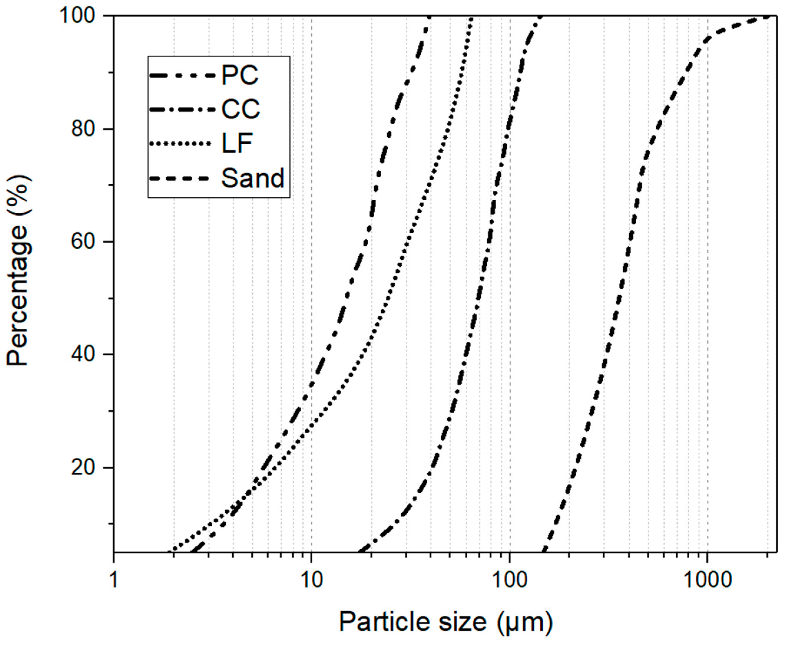
| CC | 55.1 | 38.4 | 0.6 | 2.6 | 0.2 | 3.1 | 100.0 |
| LF | 0.2 | 0 | 39.6 | 0.1 | 0 | 60.1 | 100.0 |
| Type | PC | CC | LF | Sand | Water | SP | VMA |
|---|---|---|---|---|---|---|---|
| MIX-1 | 0.4 | 0.4 | 0.2 | 1.5 | 0.3 | 0.02 | 0.0048 |
| MIX-2 | 0.4 | 0.4 | 0.2 | 1.5 | 0.3 | 0.02 | 0.0024 |
| MIX-3 | 0.4 | 0.4 | 0.2 | 1.5 | 0.3 | 0.02 | 0.0014 |
| V0 (Piston Speed in mm/s) | V (Material Flow Velocity at the Orifice in mm/s) |
|---|---|
| 0.10 | 0.90 |
| 0.25 | 2.25 |
| 0.50 | 4.50 |
| 0.75 | 6.75 |
| 1.00 | 9.00 |
| 1.25 | 11.25 |
| 1.50 | 13.50 |
| 1.75 | 15.75 |
| 2.00 | 18.00 |
| 2.25 | 20.25 |
| 2.50 | 22.50 |
| 2.75 | 24.75 |
© 2019 by the authors. Licensee MDPI, Basel, Switzerland. This article is an open access article distributed under the terms and conditions of the Creative Commons Attribution (CC BY) license (http://creativecommons.org/licenses/by/4.0/).
Share and Cite
Chen, Y.; Chaves Figueiredo, S.; Yalçinkaya, Ç.; Çopuroğlu, O.; Veer, F.; Schlangen, E. The Effect of Viscosity-Modifying Admixture on the Extrudability of Limestone and Calcined Clay-Based Cementitious Material for Extrusion-Based 3D Concrete Printing. Materials 2019, 12, 1374. https://doi.org/10.3390/ma12091374
Chen Y, Chaves Figueiredo S, Yalçinkaya Ç, Çopuroğlu O, Veer F, Schlangen E. The Effect of Viscosity-Modifying Admixture on the Extrudability of Limestone and Calcined Clay-Based Cementitious Material for Extrusion-Based 3D Concrete Printing. Materials. 2019; 12(9):1374. https://doi.org/10.3390/ma12091374
Chicago/Turabian StyleChen, Yu, Stefan Chaves Figueiredo, Çağlar Yalçinkaya, Oğuzhan Çopuroğlu, Fred Veer, and Erik Schlangen. 2019. "The Effect of Viscosity-Modifying Admixture on the Extrudability of Limestone and Calcined Clay-Based Cementitious Material for Extrusion-Based 3D Concrete Printing" Materials 12, no. 9: 1374. https://doi.org/10.3390/ma12091374