Bionic Ring Grooves Design and Experiment of the Suction Cup Applied in Oil-Immersed Substrate
by
 ,
,
Jin Xu
1, 
Lin Wang
2,
Dexue Zhang
1,3,
Xiaojie Shi
1,
Tingkun Chen
1,*,
Qian Cong
1,4,* and
Chaozong Liu
5 1
Key Laboratory of Bionic Engineering (Ministry of Education), College of Biological and Agricultural Engineering, Jilin University, Changchun 130022, China
2
State Key Laboratory of Power Systems of Tractor, YTO Group Corporation, Luoyang 471039, China
3
Shandong Academy of Agricultural Machinery Sciences, Jinan 250100, China
4
State Key Laboratory of Automotive Simulation and Control, Jilin University, Changchun 130022, China
5
Department of Ortho and MSK Science, University College London, London HA7 4LP, UK
*
Authors to whom correspondence should be addressed.
Lubricants 2023, 11(4), 152; https://doi.org/10.3390/lubricants11040152
Submission received: 16 February 2023
/
Revised: 7 March 2023
/
Accepted: 21 March 2023
/
Published: 23 March 2023
Abstract
:The vacuum suction cup is often used as an end effector and widely used in wall-climbing operations. However, there are few vacuum suction cup designs and applications for oil-immersed substrates. Inspired by the surface morphology of the octopus sucker, bionic suction cups with different numbers, diameters, and spacings of the ring grooves were designed. Their normal adsorption force was evaluated on the untreated and polished steel plate in oil. The test results showed that ring grooves positively affected the adsorption force. The bionic suction cup with a groove number of 3, a diameter of 0.5 mm, and a spacing of 3 mm was the most excellent in the test. It achieved normal adsorption forces of 54.83 ± 0.48 N and 43.89 ± 0.69 N on the untreated and polished steel plate. Compared with the standard suction cup, it increased by 32.31% and 12.28% on the untreated and polished steel plate. The regression model between the normal adsorption force and design factors was established based on the adsorption force test results, and the influence law of the ring groove structure parameters on the adsorption force of suction cups on oil-immersed substrates was analyzed. The order of significant effects of groove design parameters on normal adsorption forces was groove diameters, spacings, and numbers. The finite element analysis (FEA) results show that the ring grooves could significantly increase the contact pressure, frictional stress, and sliding distance between the suction cup and the substrate. The ring groove structure effectively improves the adsorption force of the suction cup on the oil-immersed surface by forming a more effective seal and increasing the friction force and adsorption area. This study could provide a reference for developing the actuator of the oil-immersed or lubricated climbing machine.
1. Introduction
Vacuum suction cups have many advantages, such as environmental protection, high efficiency, and low cost, and are widely used in life and industry. Suction cups are used in “simple” applications, such as hanging items on smooth surfaces of cars or houses [1]. In industry, suction cups are used in technologically complex applications, such as wall climbing [2,3,4,5], material handling [6,7], and fruit and vegetable harvesting [8,9], which involve dangerous or labor-intensive work. However, few of the current suction cups have been designed or studied for applications in oil media, which greatly limits the use of wall-climbing robots on high-risk, highly lubricated surfaces, such as oilcan. Therefore, it is necessary to study the adsorption characteristics of suction cups in oil and design high-performance suction cups suitable for applications in the lubricating medium.
Surface morphology is often used in engineering to reduce wear and lubricate the oil and gas development equipment [10]. However, it was found that many organisms also have specific morphologies on their sucker surfaces that enhance their ability to adhere to the substrate [11,12,13,14,15]. A reasonable imitation of the natural suction cup surface morphology on the artificial suction cups can effectively enhance the adsorption performance of artificial suction cups [16,17,18,19].
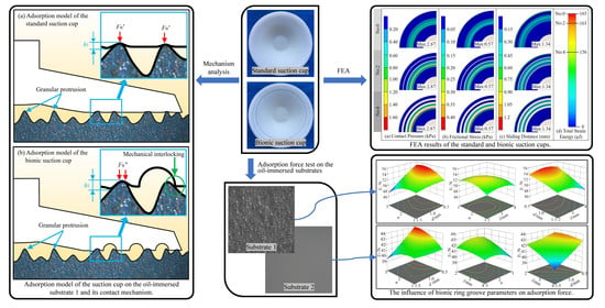
As a typical adsorbing organism, the octopus has a unique double-chambered morphology of its sucker [20]. The upper cavity is an ellipsoidal acetabular cavity. The lower cavity is funnel-shaped, the part where the sucker is attached to the substrate. Moreover, radial and ring grooves morphology exists on the surface of this cavity [21,22]. Pang et al. designed a wet-tolerant adhesive patch with a microstructure based on the double-cavity shape of the octopus sucker [23,24]. Experiments showed that the bionic patch had excellent adsorption performance on the oil-immersed substrates and showed good adhesion and water resistance on the skin surface. Tramacere et al. [25,26] designed a bionic suction cup based on the double-cavity structure of the octopus sucker. They processed the radial grooves on the surface of the funnel by laser engraving technology. It was found that the grooves improved the adsorption performance of the suction cup. Inspired by the surface morphology of octopus suckers, Xi et al. [27] designed radial grooves, herringbone grooves, and ring grooves on the contact surface of conventional suction cups, respectively. The experiments showed that the ring groove structure was more effective in improving the adsorption force of the suction cups than the other two groove structures. In summary, although the bionic patch of Pang et al. [23] obtained a strong adsorption effect on the dipping oil substrates, its adsorption patch structure is thin and difficult to process, which is unsuitable for industrial surfaces, such as the wall of oil storage tanks. The bionic suction cups developed by Tramacere and Xi et al. [26,27] are relatively simple and suitable for use in industry and on tank walls. Nevertheless, they have not investigated the performance of the suction cups on oil-immersed substrates. The law of the effect of the bionic morphology on the performance of suction cup adsorption on the dipping oil surface is still unclear.
Inspired by the surface morphology of octopus suckers [20,21,27], a series of bionic suction cups were constructed by designing the ring groove structure on the adsorption surface of the conventional suction cup in this study. The groove number, diameter, and spacing were selected as the factors for the experimental design. Standard and bionic suction cup samples were prepared by the mold method. The influence law and regression equation of the ring groove structure parameters on the adsorption force on oil-immersed substrates were obtained by testing the normal adsorption force of suction cups. Combined with the finite element analysis (FEA) method, the mechanism of the ring groove structure to improve the adsorption force of the bionic suction cups on the oil-immersed surface was discussed. The present study could provide a reference for developing mechanical end-absorbing actuators for oil-immersed or lubricated substrates for wall-climbing operations.
2. Materials and Methods
2.1. Design of Ring Groove Structure
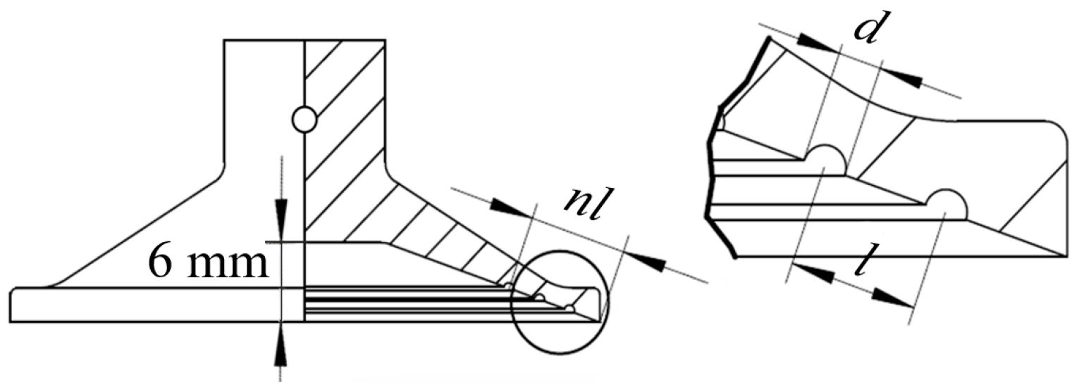
The ring groove structure on the suction cup was simulated through studies on octopus suckers [27]. The ring groove structure was designed on the contact surface of the prototype suction cup with a diameter of 55 mm. Compared to rectangular or triangular groove cross-sections, the semicircular structure is stable and less prone to crushing or tearing during operation [28]. Therefore, the semicircular groove cross-sectional morphology was taken as the bionic morphology for the bionic suction cup design. Since the diameter, number, and distribution of grooves may significantly affect the adsorption performance of suction cups on the oil-immersed substrate, the groove diameter, number, and spacing were selected as the test factors. According to the limitation of the prototype suction cup size, the research took the number of grooves n as 1~3, the groove diameter d as 0.5~1.5 mm, and the groove spacing l as 2~4 mm to implement the test, and the parameters of the bionic suction cup groove morphology are shown in Figure 1.
2.2. Fabrication of Suction Cup Samples
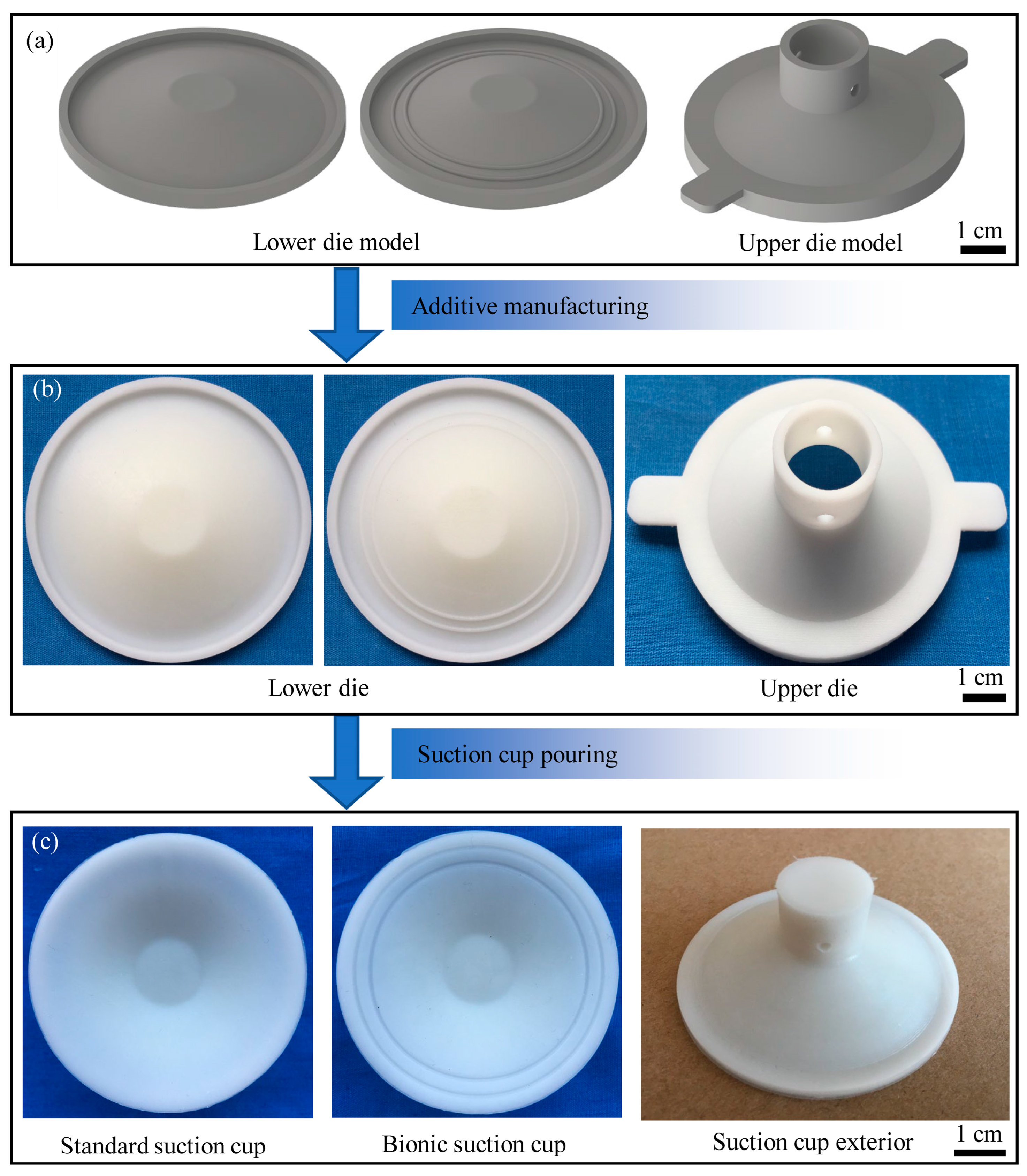
The standard and bionic suction cup test samples were fabricated by the cast die method, and the steps are shown in Figure 2. Conventional suction cup data were collected and processed by the UniSCAN 3D scanner (Creaform, Lévis, QC, Canada) and Geomagic Studio software to reconstruct the model of the prototype suction cup. The standard and bionic suction cup mold models (Figure 2a) were designed based on this model. To rapidly additive manufacture the suction cup molds, 3D printing technology was used. The ABS resin and a Lite600HD 3D precision printer (UnionTech, Shanghai, China) were used, and the physical dies are shown in Figure 2b. Mold silicone (Taibeili, Foshan, China) was used to cast the suction cup samples. The molded silicone consisted of two components. The silicone component consisted of a base adhesive (Poly (dimethylsiloxane), hydroxy terminated, (C2H6OSi)n), a cross-linking agent (Tetraethyl orthosilicate, C8H20O4Si), and a filler (Talcum powder, Mg3[Si4O10](OH)2). The curing agent component consisted of Dibutyltin dilaurate (C32H64O4Sn). The casting and demolding procession was divided into four steps: (1) A release agent would be evenly applied on the die surface. (2) Silicone and curing agent were mixed in a ratio of 100:2 and thoroughly stirred. (3) The mixture was poured into the molds and allowed to stand at ambient temperature (20 °C) for 4 h. (4) After the silicone was cured, the mold was removed and the suction cup samples obtained, as shown in Figure 2c.
2.3. Force Measurements of Suction Cup Samples
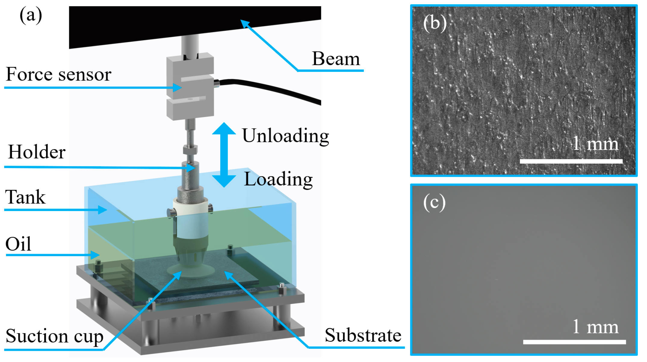
As shown in Figure 3a, the normal adsorption force of the suction cup samples on the oil-immersed substrates was tested using an electronic tensile testing machine. The maximum tensile force of the tester was 500 N, and the precision of the force sensor was 0.01 N. The adsorption force of the suction cup samples was tested on the substrates of an untreated steel plate (Ra = 78 μm) and a polished steel plate (Ra = 2 μm), and the surface morphology of the two substrates is shown in Figure 3b,c, respectively. The substrates were fixed at the bottom of the tank shown in Figure 3a. The tank was filled to 50 mm height with LN-100 industrial white oil.
The suction cup was fixed to the end of the testing machine tension sensor by a special fixture and normally pulled from the test substrate. Before the test, a preload force of 5 N was applied to the top of the suction cup, which was sufficient to collapse the chamber and release the oil inside the suction cup chamber. The load was held for <15 s before the start of the pull test. Pull tests were performed with a 200 mm/min speed of retraction. The maximum value of the force at which the suction cups were pulled out from the substrate was extracted and recorded as the suction cup adsorption force. The normal adsorption force of each sample suction cup on each substrate surface was repeated 10 times. The average adsorption force for the standard suction cup was Y0. Y1 and Y2 were calculated for the average adsorption force of bionic suction cups on the untreated and polished steel plates, respectively.
2.4. FEA of Suction Cups
FEA was conducted for the standard and bionic suction cups to understand the effect of incorporating the ring groove structure on the suction cup. In the bionic suction cup samples, the worst and best-performing suction cups in the adsorption force test were selected to be analyzed. FEA was conducted and analyzed using ANSYS Workbench 2022 R1. The suction cup with a smooth substrate model was imported into the software. The suction cup material was fitted using sample data of neoprene from the Ansys Workbench engineering data. The substrate material was structural steel by default.
Since all the suction cup samples were axisymmetric, the full model was adjusted to a one quarter symmetric model using the Geometry tool to reduce the computational time. A tetrahedral mesh was used to divide the analysis model. Set the element size to 1.0 mm and refine the mesh for the adsorption surface of the suction cups. The FEA models of the standard suction cups, the worst and best-performing bionic suction cups, had 79,285, 91,979 and 109,895 elements, respectively. Element shapes with an aspect ratio close to 1 are highly desirable in FEA for better accuracy and convergence. In the FEA model, for all cases, more than 63% of the total elements had an aspect ratio between approximately 1 and 2. The average aspect ratio of the elements was 1.94 ± 0.06.
A constant 6 mm displacement in the axial direction was imparted on the back of the suction chamber. As shown in Figure 1, because the height of the suction cup cavity was 6 mm, the displacement of 6 mm could completely collapse the inner cavity of the suction cup, which ensures the consistency of the deformation of the finite element simulation and the suction cup adsorption process. A friction contact between the inner cavity surface (adsorption surface) of the suction cup and the substrate was set. The friction coefficient between surfaces was assumed to be 0.2. In the initial state, only the inner cavity edge of the suction cup was in contact with the substrate. As the displacement was applied, the suction cup was gradually crushed, and the inner cavity surface of the suction cup and the substrate were gradually fitted to each other. The contact pressure, frictional stress, sliding distance, total deformation, and total strain energy of the collapsed suction cup were focused. The contact pressure, frictional stress, deformation of the suction cup contact surface, and the total strain energy of the suction cup were also compared for each case.
3. Results
3.1. Test Results of the Adsorption Force
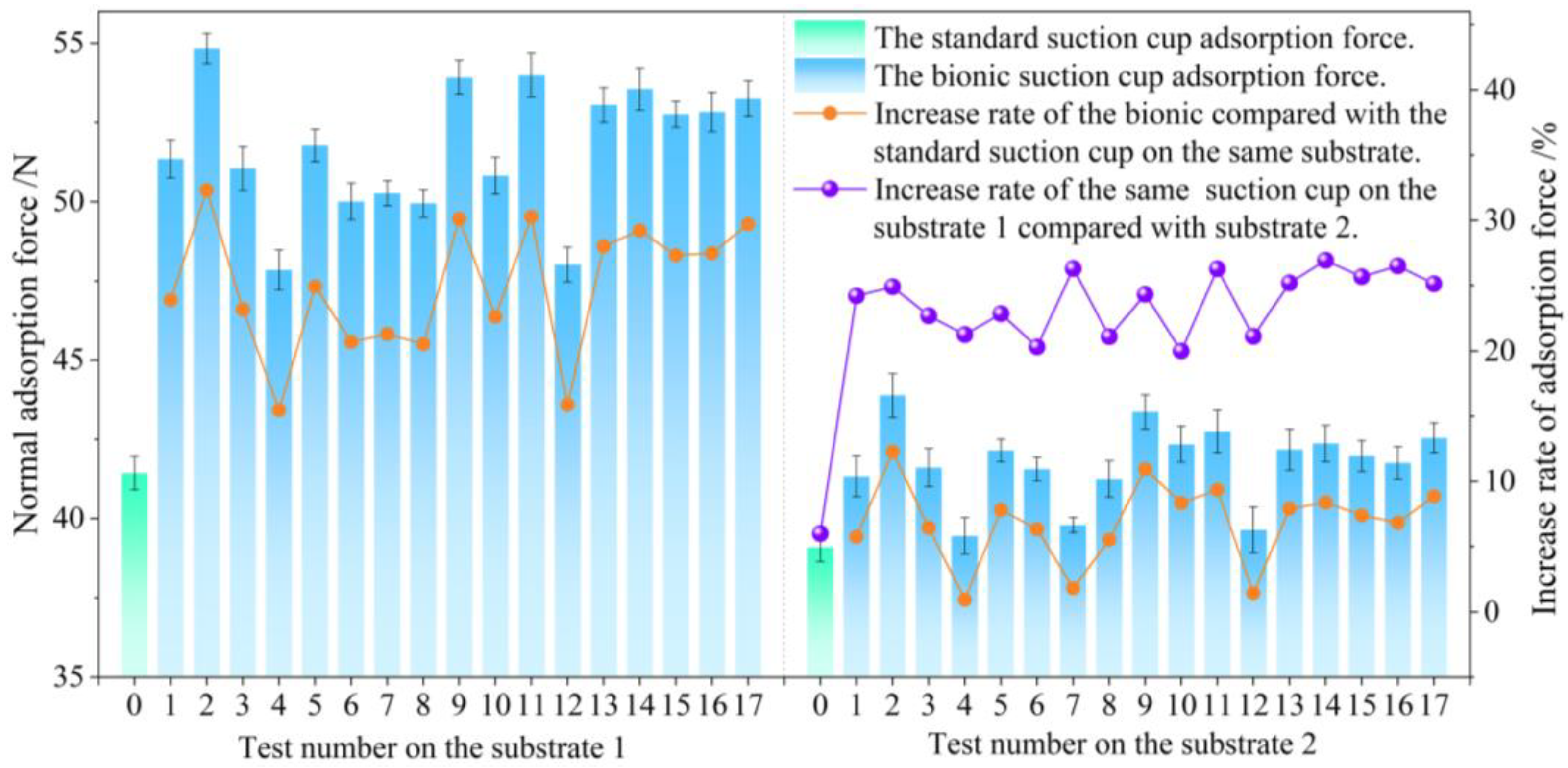
The results of the normal adsorption force tests of the standard and bionic suction cups on the substrate are shown in Figure 4. The No. 2 bionic suction cup exhibited the highest normal adsorption force among all the participating suction cup samples. The normal adsorption force on the untreated and polished steel plate reached 54.83 N and 43.89 N, respectively, which increased the adsorption force by 32.31% and 12.28% compared to the standard suction cup under the same test conditions. Compared with other bionic suction cups, the normal adsorption force value of the No. 4 sample was low. Its normal adsorption force on untreated and polished steel plates was 47.85 N and 39.46 N, respectively. However, the No. 2 and 4 suction cups only differed in groove diameter. In addition, the normal adsorption force of the bionic suction cups was always greater than the standard one on the test substrates. The normal adsorption force of the same suction cup on the untreated steel plate was always greater than the polished. At the same time, the trend of adsorption force on different substrate surfaces was approximately the same. In other words, a suction cup with a greater normal adsorption force on the untreated steel plate also exhibited a greater adsorption force on the polished steel plate. However, the difference in adsorption force indicated by bionic suction cups on both substrates was typically greater than that of the standard suction cup, with an increase in adsorption force of ≥20% for both.
The normal adsorption force test results on the suction cup samples showed that the ring grooves significantly affected the adsorption force. Regression analysis of the test results was performed using Design-Expert software. A multiple regression model of the normal adsorption force of the bionic suction cup with the number of ring grooves n, groove diameter d, and groove spacing l in natural space was established. The regression models for the adsorption force of the bionic suction cup of the untreated and polished steel plate are shown in Equations (1) and (2), respectively.
Y1 = 33.40 + 8.03 n + 9.43 d + 6.68 l − 3.34 nd + 0.36 nl − 1.44 dl − 1.50 n2 − 1.27 d2 − 1.08 l2
Y2 = 36.68 + 3.85 n + 4.77 d + 0.84 l − 2.35 nd + 0.51 nl − 1.04 dl − 0.72 n2 + 0.49 d2 − 0.26 l2
Here, Y1 is the bionic suction cup adsorption force of the untreated steel plate; Y2 is the bionic suction cup adsorption force of the polished steel plate. The ANOVA results of the two regression models are shown in Table 2. In the table, X1, X2, and X3 correspond to the coding factors for the groove number, n, the groove diameter, d, and the groove spacing, l, respectively.
Table 2 shows that the p values of both regression models were less than 0.01, indicating that the regression models were extremely significant. The p > 0.05 for the two model misfit terms indicated that the model misfit was insignificant, and the regression model fit was high. The p values of the number of grooves, groove diameter, and groove spacing could be judged that groove diameter and spacing significantly affected the suction cup adsorption force. The influence of the test factors on the suction cup adsorption force was in descending order of groove diameter, spacing, and number. Although the primary term factor p > 0.05 for the number of grooves indicated that the number of grooves was a non-significant factor, the p values for the quadratic factor and the interaction factor were less than 0.01, indicating that the number of grooves interacted with other factors in an extremely significant way. The coefficient of determination R2 of regression models (1) and (2) were 0.9751 and 0.9804. The coefficient of variation and adequate precision were 0.95%, 0.62%, 19.73, and 22.26, respectively. This indicates that the two fitted regression models of suction cup adsorption force have high reliability and can be used to guide the analysis of the effect of bionic design factors on the suction cup adsorption force.
3.2. Influencing Laws of n, d, and l on Adsorption Force
The experimental and ANOVA results showed that the diameter, spacing, and number of ring grooves affect the normal adsorption force of the suction cups to different degrees. To discuss the effects of d, l, and n on the normal adsorption force of suction cups, response surface models were constructed by fixing n, d, and l to zero levels, respectively. The effect of the other two factors on the normal adsorption force of the bionic suction cup was analyzed.
3.2.1. Influencing laws of n, d, and l on Y1
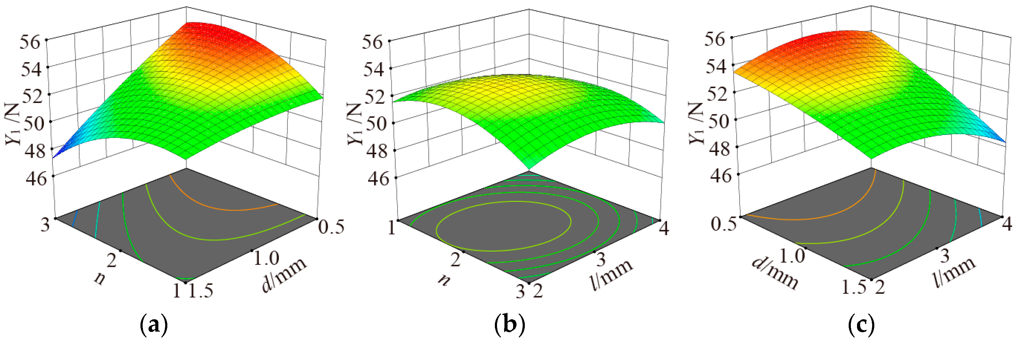
When l is fixed, the influences of n and d on Y1 are shown in Figure 5a. Y1 increased and then decreased with the increase of n. Y1 decreased with the increase of d. The bionic suction cups always had greater adsorption force when d = 0.5 mm. Moreover, the trend of Y1 decreasing with d was almost linear when n is fixed at 1, 2, and 3, respectively. Moreover, the tendency of Y1 to decrease with increasing n was more significant.
Influences of n and l on Y1 when d is fixed are shown in Figure 5b. Y1 increased and then decreased with both increases of n and l, showing a parabolic variation. However, this trend was gentle because the ANOVA results show that the interaction of n and l on Y1 was insignificant.
Influences of d and l on Y1 when n is fixed are shown in Figure 5c. Y1 increased and then decreased with an increase of l, but the fluctuation range of adsorption force change was small. Y1 decreased with the increase of d. Moreover, the trend was also close to a linear decrease when fixing l to a fixed value.
3.2.2. Influencing laws of n, d, and l on Y2
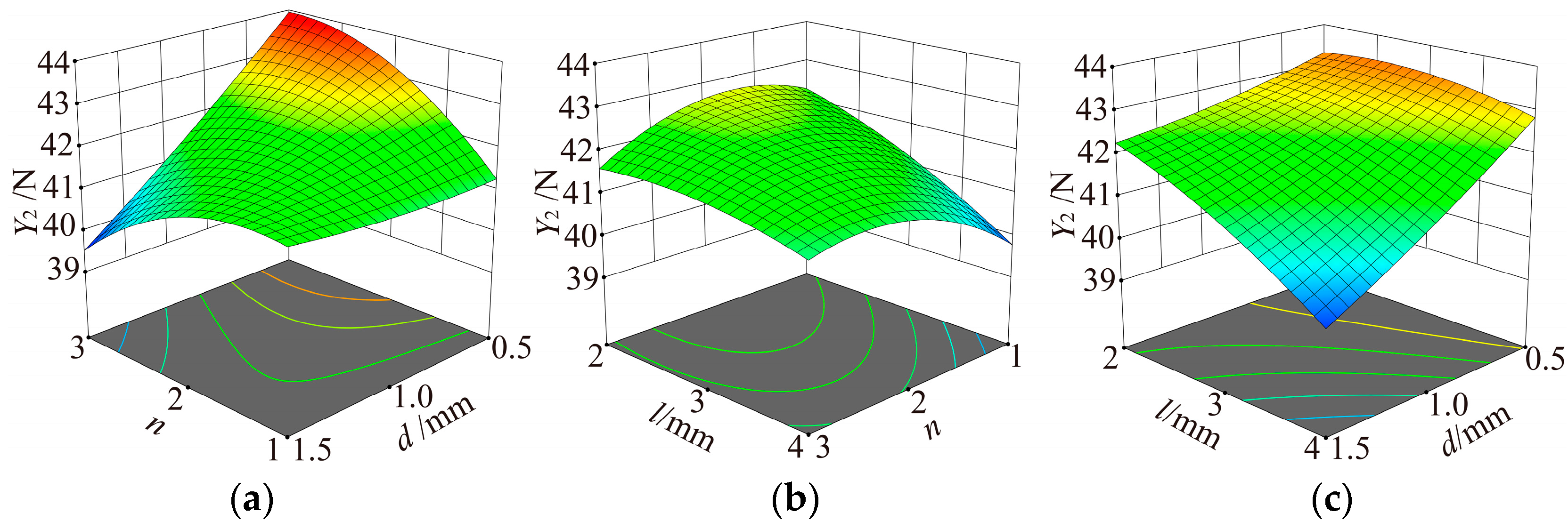
When l is fixed, the influences of d and n on Y2 are shown in Figure 6a. Y2 decreased with increasing d. However, compared to the linear decrease of Y2 with d, the trend of Y2 decreasing with d is no longer linear. The rate of reduction of Y2 decreased with increasing d. The variation of Y2 with increasing n was complex and interesting. The ANOVA results demonstrate that the interaction between n and d was extremely significant for Y2. When d takes small values, Y2 increases with increasing n. However, when d takes larger values, Y2 decreases with increasing n.
Influences of n and l on Y2 when d is fixed are shown in Figure 6b. Y2 increased and then decreased as n increased, and Y2 decreased as l increased.
Influences of d and l on Y2 when n is fixed are shown in Figure 6c. Y2 decreased with the increase of l and d. Furthermore, the rate of Y2 decrease gradually increased with the increase of the factor level.
3.3. Test Results of FEA
FEA was performed on the standard and bionic suction cups with the best and worst performance in normal adsorption force. From the normal adsorption force test results, the best and worst performing bionic suction cups were No. 2 and No. 4, respectively. The FEA results of the standard, No. 2, and No. 4 suction cups are shown in Figure 7.
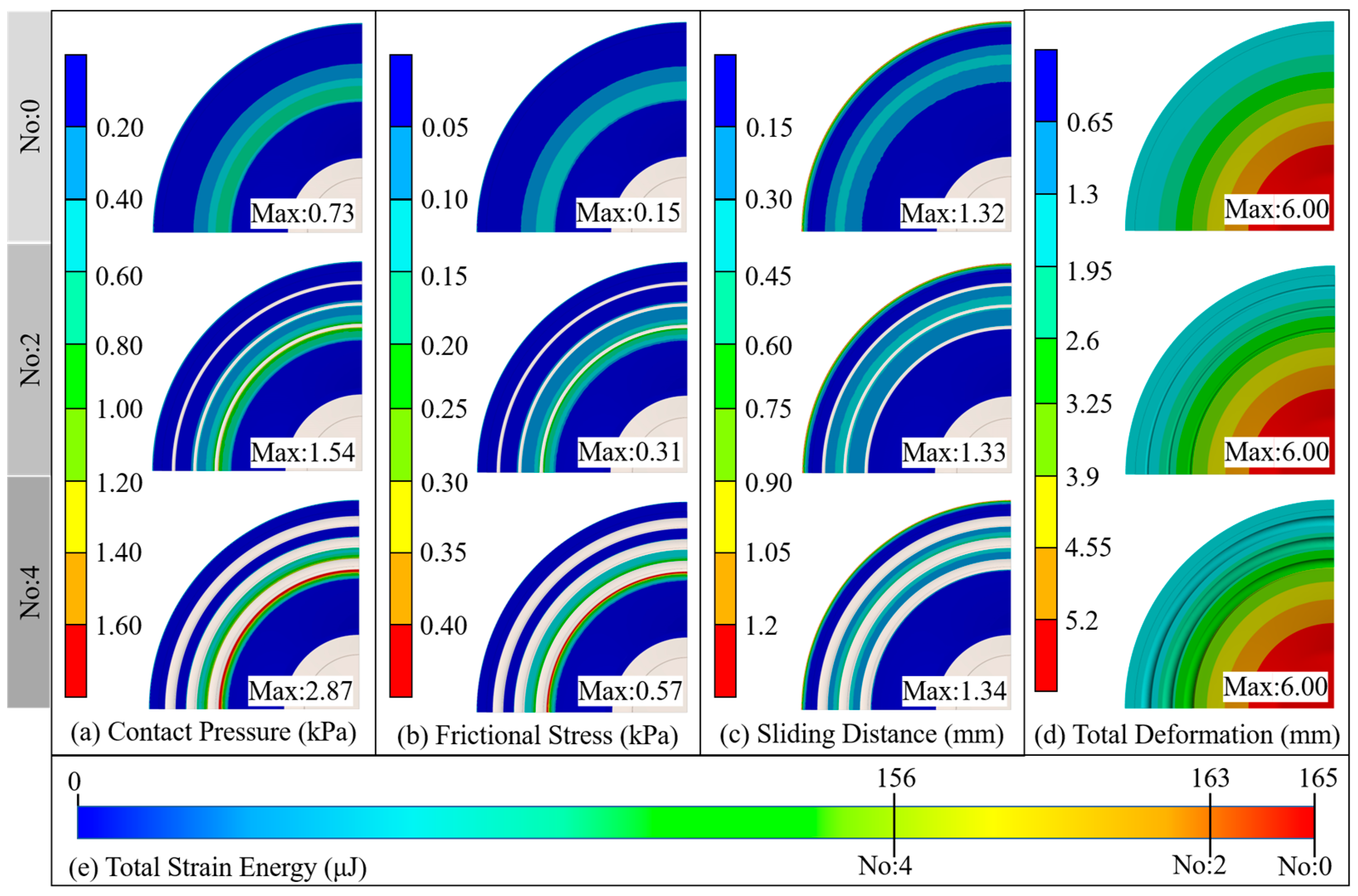
The lateral comparison of Figure 7 shows that the contact pressure, friction stress, sliding distance, and total deformation on the standard suction cup adsorption surface were distributed in a continuous ring shape. The enormous pressure and friction regions were distributed in the middle of the generatrix of the suction cup’s inner cavity, and the maximum sliding distance appeared at the edge of the adsorption surface. A longitudinal comparison of Figure 7 shows that the main distribution areas of contact pressure, frictional stress, sliding distance, and total deformation on the adsorption surface of the bionic suction cup were similar to those of the standard suction cup. However, the enormous pressure and friction regions on the adsorption surface of the bionic suction cup were divided by the ring groove structure, forming multiple discontinuous large pressure and large friction rings. In addition, compared with the standard suction cup, the maximum values of contact pressure, friction stress, and sliding distance on the adsorption surface of the bionic suction cup were increased to different degrees. The FEA results showed that the worst-performing bionic suction cup in the normal adsorption force test, No. 4, had larger surface contact pressure, frictional stress, and sliding distance. The total strain energy analysis results of the suction cups (Figure 7e) were opposed to the surface stress and sliding distance performance. The standard suction cup had the largest total elastic energy, and the No. 4 suction cup had the smallest total strain energy. In contrast, the best-performing suction cup in the normal adsorption force test, No. 2, had moderate total strain energy for both the maximum values of surface contact pressure, frictional stress, and sliding distance, as well as the total strain energy of the suction cup.
4. Discussion
The test results showed that the adsorption force of the bionic suction cups with ring grooves was always greater than that of the standard suction cup. The FEA results of the suction cup on the smooth plane indicated that the ring groove divides the high-pressure area and the large friction area on their contact surface. It made a multi-ring seal between the bionic suction cup and the substrate, which could effectively reduce leakage during adsorption. Besides, the simulation results showed a larger contact pressure between the bionic suction cup and the substrate. The contact pressure contributes to the bonding and sealing of the contact surface, indicating that the bionic suction cups’ contact performance was better than the standard one. The coupling effect of the multi-ring seal and a better-sealing property contributed to the formation and maintenance of negative pressure during the pull-off process of the suction cup. The bionic suction cup could form a stronger negative pressure than the standard suction cup at the same pull-off displacement.
The FEA results showed that a larger friction stress was formed between the bionic suction cup and the substrate. It is comforting that the suction cup had a larger frictional force in oil was what we expected. The adsorption surface of the suction cup would contract radially during the pull-off process, while the friction force could effectively inhibit the sliding between the contact surfaces. The bionic suction cup could maintain a larger adsorption area than the standard suction cup under the same pull-off displacement.
Compared with the standard suction cup, bionic suction cups could produce a larger radial extension sliding during the adsorption process, resulting in a larger adsorption area. According to the adsorption force formula F = PS (P: pressure, S: adsorption area), the bionic suction cup had a stronger negative pressure or a larger adsorption area at the same pull-off displacement, which would improve the bionic suction cup adsorption force.
The total strain energy analysis results revealed that the strain energy of the standard, No. 2, and No. 4 suction cups decreased sequentially. The work performed by the initial compression was either stored in the body as strain energy or performed on the fluid within the suction chamber to evacuate the suction chamber and form a vacuum [19]. Therefore, a suction cup with lower strain energy would work more on the fluid and be more closely attached to the substrate when the same constraints were applied to the suction cup. This promoted the suction cup to form a more effective seal with the substrate surface while discharging more fluid, thereby increasing the adsorption force of the suction cup. It was also the reason for the larger contact pressure between the bionic suction cup and the substrate.
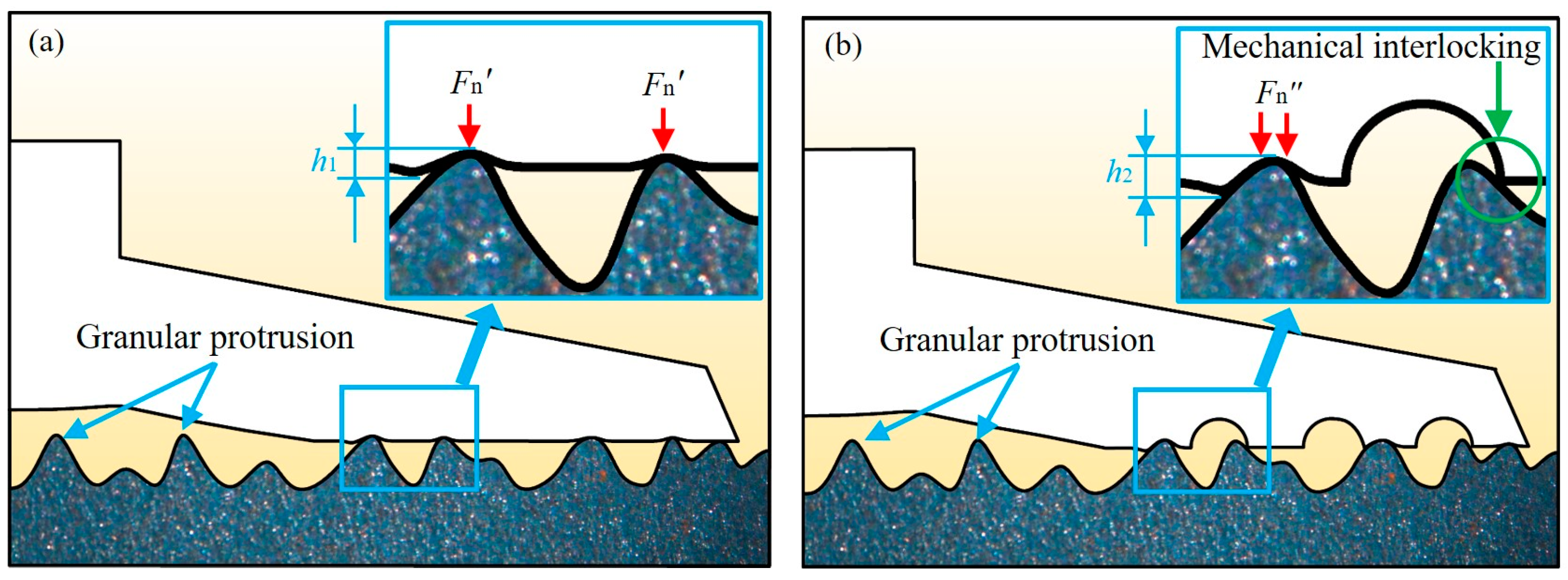
Compared with the polished steel plate, the suction cup showed a stronger adsorption force on the untreated steel plate, whether standard or bionic suction cup. According to the observation of the substrate surface in Figure 2, the untreated steel plate was a non-smooth surface with many micron-sized granular protrusions. Therefore, when the suction cups were adsorbed onto the untreated steel plate by negative pressure, the granular protrusions on the substrate surface would be embedded in the relatively soft suction cups. As shown in Figure 8, the contact surface would form many stress concentration areas at the top of the granular protrusions, which could improve the local friction between the suction cup and the substrate. These frictions inhibited the radial sliding during the pull-off process to a certain extent, which promoted the standard suction cup to induce a stronger adsorption force on the untreated steel plate.
It was assumed that the height of the granular protrusion embedded in the suction cup was h, as shown in Figure 8. According to the FEA results, the bionic suction cups always created a larger contact pressure on the contact surface. Therefore, the height h1 of the granular protrusion embedded in the standard suction cup was much lower than the height h2 of the bionic suction cups. The bionic suction cups could form a larger local normal pressure in the granular protrusions. According to the friction formula f = μFn (μ: dynamic friction factor; Fn: normal pressure), the bionic suction cups could create larger friction than the standard one.
Furthermore, the ring groove structure of the bionic suction cup could form a mechanical interlocking [32] similar to biological attachment with the granular protrusions on the substrate. This would effectively inhibit the radial contraction of the suction cup during the pull-off process and maintain the adsorption state. Mechanical interlocking is significant for the stability of suction cup adsorption in lubricated media.
The ring groove design parameters had an important influence on the suction cup adsorption force. The influence of the test factors on the suction cup adsorption force was in descending order of groove diameter, spacing, and number.
FEA results showed that a larger groove diameter d would increase the contact pressure and frictional stress between the suction cup and the substrate more efficiently, thus effectively improving the sealing and friction performance of the suction cup. However, the test results showed that the adsorption force always decreased with the increase of d on both polished and untreated steel plates. As d increased, the wall thickness at the groove position gradually decreased, which caused a decrease in the structural strength of the suction cup. The reduction of the structural strength of the suction cup would weaken its anti-deformation ability, resulting in a greater tendency for radial shrinkage during the pull-off process, thereby reducing the adsorption force.
According to the ANOVA results, the groove spacing l had a significant affection for the adsorption force. The adsorption force always decreased with the increase of l in this study. The l determined the grooves distribution position on the generatrix of the suction cup’s inner cavity. Along the direction of the generatrix, the wall thickness of the suction cup gradually decreased and thickened at the edge. Therefore, the groove with the same d and different l had different effects on the structural strength of the suction cup structure. With the increase of l, the distribution of grooves was gradually close to the thin-walled area, which greatly weakened the local structural strength of the suction cup and thus reduced its adsorption force.
The ANOVA results showed that the number of grooves n was a non-significant factor. However, the interaction between the n and d was extremely significant. As a quantitative design factor, n would significantly enhance the influence of d. When d was maintained at a high level, the adsorption force decreased significantly with increasing n. However, when d was maintained at a low level, the suction adsorption force increased with increasing n. Since d was small, the grooves had less influence on the structural strength of the suction cup. At this point, as n increased, the reduction in the total strength of the suction cup was small, but multi-ring seals were formed. The multi-ring seals effectively improved the suction cup’s sealing and frictional properties, which improved the suction cup’s adsorption force.
5. Conclusions
In this study, inspired by the surface morphology of the octopus sucker, the bionic suction cups with ring grooves were designed on the conventional suction cup based on the number, diameter, and spacing factors of ring grooves. The normal adsorption force of bionic sucker samples in the oil medium was tested. Lastly, the adsorption mechanism was interpreted by proposing an adsorption model through FEA. Based on the results obtained and discussed, the following conclusions are drawn:
- The maximum normal adsorption force of the bionic suction cup sample on the untreated and polished steel plate substrates increased by 32.31 % and 12.28 %, respectively, compared with the standard suction cup. The suction cups have stronger adsorption force on the untreated steel plate.
- The bionic ring grooves could improve the adsorption force of suction cups on oil-immersed substrates. The significant order of the influence of the test factors of the ring groove structure on the adsorption force of the sucker was groove diameter, spacing, and number.
- The bionic ring grooves improved the sealing performance of the bionic suction cup by dividing and increasing the contact pressure between the suction cup and the substrate to form multi-ring seals.
- The bionic ring grooves increased the frictional stress between the suction cup and the substrate.
- The ring grooves increased the adsorption area of the bionic suction cup.
- The ring grooves formed a mechanical interlocking with the granular protrusions on the substrate, which would effectively inhibit the radial contraction of the suction cup during the pull-off process and maintain the adsorption state.
The present study could develop mechanical end-absorbing actuators for oil-immersed or lubricated substrates, such as wall-climbing operations.
Author Contributions
Conceptualization, J.X., L.W., D.Z., T.C. and Q.C.; methodology, J.X., L.W., X.S., T.C., Q.C. and C.L.; validation, J.X., D.Z., X.S. and T.C.; formal analysis, J.X., L.W., D.Z., X.S., T.C. and C.L.; investigation, J.X., L.W., T.C. and Q.C.; resources, L.W. and Q.C.; data curation, J.X., D.Z., X.S., T.C. and Q.C.; writing—original draft preparation, J.X. and T.C.; writing—review and editing, J.X., T.C., Q.C. and C.L.; visualization, J.X., D.Z., X.S. and Q.C.; supervision, T.C. and Q.C.; project administration, T.C. and Q.C. All authors have read and agreed to the published version of the manuscript.
Funding
This research was supported by the State Key Laboratory of Power Systems of Tractor, China (Grant No. SKT2022002), the National Natural Science Foundation of China (Grant No. 51775234), the Science and Technology Development Program of Jilin Province, China (Grant No. 20190302101GX).
Data Availability Statement
The data supporting the findings of this study are available in the article.
Conflicts of Interest
On behalf of all authors, the corresponding author states that there is no conflict of interest. The funder had no role in the design of the study; in the collection, analysis, or interpretation of data; in the writing of the manuscript; or in the decision to publish the results.
Nomenclature
| n | groove number |
| d | groove diameter |
| l | groove spacing |
| Y0 | the average adsorption force for the standard suction cup |
| Y1 | the average adsorption force of bionic suction cups on the untreated steel plate |
| Y2 | the average adsorption force of bionic suction cups on the polished steel plate |
| X1 | coding factors for the groove number |
| X2 | coding factors for the groove diameter |
| X3 | coding factors for the groove spacing |
| df | degree of freedom |
| R2 | the coefficient of determination |
| F | adsorption force |
| P | pressure |
| S | adsorption area |
| h, h1, h2 | the height of the granular protrusion embedded in the suction cup |
| f | friction |
| μ | dynamic friction factor |
| Fn, Fn′, Fn″ | normal pressure |
References
- Tiwari, A.; Persson, B.N.J. Physics of Suction Cups. Soft Matter 2019, 15, 9482–9499. [Google Scholar] [CrossRef]
- Fang, Y.; Wang, S.; Bi, Q.; Cui, D.; Yan, C. Design and Technical Development of Wall-Climbing Robots: A Review. J. Bionic Eng. 2022, 19, 877–901. [Google Scholar] [CrossRef]
- Liu, J.; Xu, L.; Chen, S.; Xu, H.; Cheng, G.; Xu, J. Development of a Bio-Inspired Wall-Climbing Robot Composed of Spine Wheels, Adhesive Belts and Eddy Suction Cup. Robotica 2021, 39, 3–22. [Google Scholar] [CrossRef]
- Brusell, A.; Andrikopoulos, G.; Nikolakopoulos, G. A Survey on Pneumatic Wall-Climbing Robots for Inspection. In Proceedings of the 2016 24th Mediterranean Conference on Control and Automation (MED), Athens, Greece, 21–24 June 2016; IEEE: New York, NY, USA, 2016; pp. 220–225. [Google Scholar]
- Xu, J.; Xu, L.; Liu, J.; Li, X.; Wu, X. Survey on Bioinspired Adhesive Methods and Design and Implementation of a Multi-Mode Biomimetic Wall-Climbing Robot. In Proceedings of the 2018 IEEE/ASME International Conference on Advanced Intelligent Mechatronics (AIM), Auckland, New Zealand, 9–12 July 2018; IEEE: New York, NY, USA, 2018; pp. 688–693. [Google Scholar]
- Kang, L.; Seo, J.-T.; Kim, S.-H.; Kim, W.-J.; Yi, B.-J. Design and Implementation of a Multi-Function Gripper for Grasping General Objects. Appl. Sci. 2019, 9, 5266. [Google Scholar] [CrossRef] [Green Version]
- Pham, H.; Pham, Q.-C. Critically Fast Pick-and-Place with Suction Cups. In Proceedings of the 2019 International Conference on Robotics and Automation (ICRA), Montreal, QC, Canada, 20–24 May 2019; IEEE: New York, NY, USA, 2019; pp. 3045–3051. [Google Scholar]
- Hemming, J.; van Tuijl, B.A.J.; Gauchel, W.; Wais, E. Field Test of Different End-Effectors for Robotic Harvesting of Sweet-Pepper. Acta Hortic. 2016, 1130, 567–574. [Google Scholar] [CrossRef]
- Kurpaska, S.; Sobol, Z.; Pedryc, N.; Hebda, T.; Nawara, P. Analysis of the Pneumatic System Parameters of the Suction Cup Integrated with the Head for Harvesting Strawberry Fruit. Sensors 2020, 20, 4389. [Google Scholar] [CrossRef]
- Gao, T.; Zhang, H.; Xu, J.; Ma, B.; Cong, Q. Effects of Cylindrical Pit Array on Tribological Property of Piston–Cylinder Sleeve Friction Pair in a BW-250 Slime Pump. Tribol. Int. 2020, 151, 106505. [Google Scholar] [CrossRef]
- Cong, Q.; Xu, J.; Fan, J.; Chen, T.; Ru, S. Insights into the Multilevel Structural Characterization and Adsorption Mechanism of Sinogastromyzon Szechuanensis Sucker on the Rough Surface. Life 2021, 11, 952. [Google Scholar] [CrossRef] [PubMed]
- Greco, G.; Bosia, F.; Tramacere, F.; Mazzolai, B.; Pugno, N.M. The Role of Hairs in the Adhesion of Octopus Suckers: A Hierarchical Peeling Approach. Bioinspir. Biomim. 2020, 15, 035006. [Google Scholar] [CrossRef]
- Xi, P.; Cong, Q.; Xu, J.; Sun, L. Surface Movement Mechanism of Abalone and Underwater Adsorbability of Its Abdominal Foot. Bioinspired Biomim. Nanobiomater. 2019, 8, 254–262. [Google Scholar] [CrossRef]
- Persson, B.N.J. Wet Adhesion with Application to Tree Frog Adhesive Toe Pads and Tires. J. Phys. Condens. Matter 2007, 19, 376110. [Google Scholar] [CrossRef]
- Sandoval, J.A.; Sommers, J.; Peddireddy, K.R.; Robertson-Anderson, R.M.; Tolley, M.T.; Deheyn, D.D. Toward Bioinspired Wet Adhesives: Lessons from Assessing Surface Structures of the Suction Disc of Intertidal Clingfish. ACS Appl. Mater. Interfaces 2020, 12, 45460–45475. [Google Scholar] [CrossRef] [PubMed]
- Wang, Y.; Yang, X.; Chen, Y.; Wainwright, D.K.; Kenaley, C.P.; Gong, Z.; Liu, Z.; Liu, H.; Guan, J.; Wang, T.; et al. A Biorobotic Adhesive Disc for Underwater Hitchhiking Inspired by the Remora Suckerfish. Sci. Robot. 2017, 2, eaan8072. [Google Scholar] [CrossRef] [Green Version]
- Gamel, K.M.; Garner, A.M.; Flammang, B.E. Bioinspired Remora Adhesive Disc Offers Insight into Evolution. Bioinspir. Biomim. 2019, 14, 056014. [Google Scholar] [CrossRef]
- Ditsche, P.; Summers, A. Learning from Northern Clingfish (Gobiesox maeandricus): Bioinspired Suction Cups Attach to Rough Surfaces. Philos. Trans. R. Soc. B 2019, 374, 20190204. [Google Scholar] [CrossRef] [Green Version]
- Sandoval, J.A.; Jadhav, S.; Quan, H.; Deheyn, D.D.; Tolley, M.T. Reversible Adhesion to Rough Surfaces Both in and out of Water, Inspired by the Clingfish Suction Disc. Bioinspir. Biomim. 2019, 14, 066016. [Google Scholar] [CrossRef] [PubMed]
- Tramacere, F.; Beccai, L.; Kuba, M.; Gozzi, A.; Bifone, A.; Mazzolai, B. The Morphology and Adhesion Mechanism of Octopus vulgaris Suckers. PLoS ONE 2013, 8, e65074. [Google Scholar] [CrossRef] [Green Version]
- Kier, W.M. The Structure and Adhesive Mechanism of Octopus Suckers. Integr. Comp. Biol. 2002, 42, 1146–1153. [Google Scholar] [CrossRef] [Green Version]
- Tramacere, F.; Appel, E.; Mazzolai, B.; Gorb, S.N. Hairy Suckers: The Surface Microstructure and Its Possible Functional Significance in the Octopus vulgaris Sucker. Beilstein J. Nanotechnol. 2014, 5, 561–565. [Google Scholar] [CrossRef] [Green Version]
- Baik, S.; Kim, D.W.; Park, Y.; Lee, T.-J.; Ho Bhang, S.; Pang, C. A Wet-Tolerant Adhesive Patch Inspired by Protuberances in Suction Cups of Octopi. Nature 2017, 546, 396–400. [Google Scholar] [CrossRef]
- Chun, S.; Kim, D.W.; Baik, S.; Lee, H.J.; Lee, J.H.; Bhang, S.H.; Pang, C. Conductive and Stretchable Adhesive Electronics with Miniaturized Octopus-Like Suckers against Dry/Wet Skin for Biosignal Monitoring. Adv. Funct. Mater. 2018, 28, 1805224. [Google Scholar] [CrossRef]
- Follador, M.; Tramacere, F.; Mazzolai, B. Dielectric Elastomer Actuators for Octopus Inspired Suction Cups. Bioinspir. Biomim. 2014, 9, 046002. [Google Scholar] [CrossRef] [PubMed]
- Tramacere, F.; Follador, M.; Pugno, N.M.; Mazzolai, B. Octopus-like Suction Cups: From Natural to Artificial Solutions. Bioinspir. Biomim. 2015, 10, 035004. [Google Scholar] [CrossRef]
- Xi, P.; Cong, Q.; Xu, J.; Qiu, K. Design, Experiment and Adsorption Mechanism Analysis of Bionic Sucker Based on Octopus Sucker. Proc. Inst. Mech. Eng. H 2019, 233, 1250–1261. [Google Scholar] [CrossRef] [PubMed]
- Wang, L.; Ha, K.-H.; Qiao, S.; Lu, N. Suction Effects of Crater Arrays. Extrem. Mech. Lett. 2019, 30, 100496. [Google Scholar] [CrossRef]
- Xu, X.H.; He, M.Z. Experimental Design and Application of Design-Expert and SPSS; Science Press: Beijing, China, 2010. [Google Scholar]
- Ge, Y.Y. Experimental Design Method and Design-Expert Software Application; Harbin Institute of Technology Press: Harbin, China, 2015. [Google Scholar]
- Ren, L.Q. Experimental Design and Optimization, 1st ed.; Science Press: Beijing, China, 2009. [Google Scholar]
- Gorb, S.N. Biological Attachment Devices: Exploring Nature’s Diversity for Biomimetics. Philos. Trans. R. Soc. A 2008, 366, 1557–1574. [Google Scholar] [CrossRef] [PubMed]
Figure 1.
Bionic suction cups design diagram.

Figure 2.
The preparation process of the suction cup samples. (a) The suction cup sample mold models; (b) The suction cup sample physical dies; (c) The appearance of suction cup samples.
Figure 2.
The preparation process of the suction cup samples. (a) The suction cup sample mold models; (b) The suction cup sample physical dies; (c) The appearance of suction cup samples.

Figure 3.
Schematic depiction of adsorption force measurements. (a) Adsorption force testing device; (b) Substrate 1: untreated steel plate (Ra = 78 μm); (c) Substrate 2: polished steel plate (Ra = 2 μm).
Figure 3.
Schematic depiction of adsorption force measurements. (a) Adsorption force testing device; (b) Substrate 1: untreated steel plate (Ra = 78 μm); (c) Substrate 2: polished steel plate (Ra = 2 μm).

Figure 4.
Adsorption force and its increase rate.

Figure 5.
The influences of d, l and n on Y1. (a) l = 3 mm; (b) d = 1 mm; (c) n = 2.

Figure 6.
The influences of d, l and n on Y2. (a) l = 3 mm; (b) d = 1 mm; (c) n = 2.

Figure 7.
FEA results of the suction cups. (a) The contact pressure results of the suction cup adsorption surface; (b) The friction stress results of the suction cup adsorption surface; (c) The sliding distance results of the suction cup adsorption surface; (d) The total deformation results of the suction cup adsorption surface; (e) The total strain energy results of the suction cups.

Figure 8.
Adsorption model of the suction cup on the untreated steel plate. (a) Adsorption model of the standard suction cup; (b) Adsorption model of the bionic suction cup.
Figure 8.
Adsorption model of the suction cup on the untreated steel plate. (a) Adsorption model of the standard suction cup; (b) Adsorption model of the bionic suction cup.


Table 1.
Numbers of the testing suction cup samples and factor levels.
| Test Number | n | d/mm | l/mm | Test Number | n | d/mm | l/mm |
|---|---|---|---|---|---|---|---|
| 0 | 0 | 0 | 0 | 9 | 2 | 0.5 | 2.0 |
| 1 | 1 | 0.5 | 3.0 | 10 | 2 | 1.5 | 2.0 |
| 2 | 3 | 0.5 | 3.0 | 11 | 2 | 0.5 | 4.0 |
| 3 | 1 | 1.5 | 3.0 | 12 | 2 | 1.5 | 4.0 |
| 4 | 3 | 1.5 | 3.0 | 13 | 2 | 1.0 | 3.0 |
| 5 | 1 | 1.0 | 2.0 | 14 | 2 | 1.0 | 3.0 |
| 6 | 3 | 1.0 | 2.0 | 15 | 2 | 1.0 | 3.0 |
| 7 | 1 | 1.0 | 4.0 | 16 | 2 | 1.0 | 3.0 |
| 8 | 3 | 1.0 | 4.0 | 17 | 2 | 1.0 | 3.0 |
Table 2.
Variance analysis of the quadratic model of bionic suction cup adsorption force.
| Source | Adsorption Force on the Untreated Steel Plate | Adsorption Force on the Polished Steel Plate | ||||||
|---|---|---|---|---|---|---|---|---|
| Sum of Squares | df | F Value | p Value | Sum of Squares | df | F Value | p Value | |
| Model | 65.98 | 9 | 30.43 | <0.01 | 23.44 | 9 | 38.85 | <0.01 |
| X1-n | 0.41 | 1 | 1.70 | >0.05 | 0.20 | 1 | 3.01 | >0.05 |
| X2-d | 33.42 | 1 | 138.73 | <0.01 | 8.57 | 1 | 127.82 | <0.01 |
| X3-l | 2.31 | 1 | 9.60 | <0.05 | 4.49 | 1 | 66.90 | <0.01 |
| X1X2 | 11.16 | 1 | 46.31 | <0.01 | 5.52 | 1 | 82.37 | <0.01 |
| X1X3 | 0.53 | 1 | 2.18 | >0.05 | 1.03 | 1 | 15.37 | <0.01 |
| X2X3 | 2.06 | 1 | 8.55 | <0.05 | 1.08 | 1 | 16.13 | <0.01 |
| X12 | 9.49 | 1 | 39.41 | <0.01 | 2.15 | 1 | 32.13 | <0.01 |
| X22 | 0.42 | 1 | 1.75 | >0.05 | 0.06 | 1 | 0.94 | >0.05 |
| X32 | 4.95 | 1 | 20.54 | <0.01 | 0.29 | 1 | 4.25 | >0.05 |
| Residual | 1.69 | 7 | 0.47 | 7 | ||||
| Lake of fit | 1.27 | 3 | 4.08 | >0.05 | 0.08 | 3 | 0.28 | >0.05 |
| Pure error | 0.42 | 4 | 0.39 | 4 | ||||
| Total | 67.66 | 16 | 23.91 | 16 | ||||
Disclaimer/Publisher’s Note: The statements, opinions and data contained in all publications are solely those of the individual author(s) and contributor(s) and not of MDPI and/or the editor(s). MDPI and/or the editor(s) disclaim responsibility for any injury to people or property resulting from any ideas, methods, instructions or products referred to in the content. |
© 2023 by the authors. Licensee MDPI, Basel, Switzerland. This article is an open access article distributed under the terms and conditions of the Creative Commons Attribution (CC BY) license (https://creativecommons.org/licenses/by/4.0/).
Share and Cite
MDPI and ACS Style
Xu, J.; Wang, L.; Zhang, D.; Shi, X.; Chen, T.; Cong, Q.; Liu, C. Bionic Ring Grooves Design and Experiment of the Suction Cup Applied in Oil-Immersed Substrate. Lubricants 2023, 11, 152. https://doi.org/10.3390/lubricants11040152
AMA Style
Xu J, Wang L, Zhang D, Shi X, Chen T, Cong Q, Liu C. Bionic Ring Grooves Design and Experiment of the Suction Cup Applied in Oil-Immersed Substrate. Lubricants. 2023; 11(4):152. https://doi.org/10.3390/lubricants11040152
Chicago/Turabian StyleXu, Jin, Lin Wang, Dexue Zhang, Xiaojie Shi, Tingkun Chen, Qian Cong, and Chaozong Liu. 2023. "Bionic Ring Grooves Design and Experiment of the Suction Cup Applied in Oil-Immersed Substrate" Lubricants 11, no. 4: 152. https://doi.org/10.3390/lubricants11040152
Note that from the first issue of 2016, this journal uses article numbers instead of page numbers. See further details here.