An Inland Shore Control Centre for Monitoring or Controlling Unmanned Inland Cargo Vessels

 , , , ,
Abstract
:
1. Introduction
- I.
- Use an ACD approach [11] to develop an I-SCC concept which provides its operator with interaction possibilities with a USV, where interaction denotes the remote access of the USV actuation system and overall system settings. Accordingly, this I-SCC aims to serve as a tool to enhance the situation awareness [13] and sensemaking [14] capabilities of the remote operator. Thus, the I-SCC unlocks research on the impacts on ship sense [15] and harmony [16] when remotely monitoring or controlling a USV.
- II.
- Translate this I-SCC concept into four design requirements: (r-i.) provide the relevant information groups of [12], (r-ii.) provide interaction with the USV, (r-iii.) select industrial components, and (r iv.) keep the design modular.
- III.
- Provide technological details of the merged I-SCC and USV system design in accordance with these four design requirements.
- IV.
- Offer preliminary experimental data of an operator remotely controlling a USV via the I-SCC. These experiments investigate the performance of the system and of its operator.
- V.
- Illustrate the modular design philosophy by extending the I-SCC design within the Hull-To-Hull (H2H) project [17] which augments the remote motion control of a USV via the I-SCC. The change in operator performance due to this extension was also investigated.
2. Background: Towards Unmanned Inland Shipping
2.1. The European Inland Waterway Transport Sector
2.2. Unmanned Inland Cargo Vessels
2.2.1. The Cogge-Watertruck Scale Model
2.2.2. The Maverick-the Pallet Barge Scale Model
2.2.3. Line-Of-Sight Control Subsystem
3. Concept and Requirements of an Inland Shore Control Centre
3.1. Concept of an Inland Shore Control Centre
3.1.1. Ship Sense and Harmony
3.1.2. Situation Awareness, Sensemaking, and Interaction
3.1.3. Activity-Centred Design Concept of an Inland Shore Control Centre
3.2. Design Requirements of an Inland Shore Control Centre
- (r-i.)
- Generate and communicate elements of the information groups [12] (ii) sailing, (iii) observations, (iv) safety and emergencies, (v) security, and (vii) technical to the I-SCC. These groups will enhance the situational awareness and sensemaking abilities of the remote operator.
- (r-ii.)
- Provide interaction possibilities with the USV in order to remotely alter the USV motion and its system configurations. This interaction will also assist the sensemaking and situation awareness capabilities of the operator.
- (r-iii.)
- Install industrial, marine-grade components for both the extensions on the USV and the I-SCC system design. This requirement makes the overall system more safe, more robust, and fit closer to a potential future reality.
- (r-iv.)
- Keep the system design modular and flexible, where possible. This flexibility smoothens the likely design iterations and potential future system extensions.
3.3. The Hull-To-Hull Navigation Concept
3.4. Risk and Safety Analysis of an Inland Shore Control Centre
4. Design and Construction of an Inland Shore Control Centre
4.1. Technical Design of an Inland Shore Control Centre
4.1.1. Design Results for Requirement One (R-I.)
4.1.2. Design Results for Requirement Two (R-Ii.)
4.1.3. Design Results for Requirement Three and Four (R-Iii.–R-Iv.)
4.2. Construction of an Inland Shore Control Centre
4.3. Technical Design Hull-To-Hull-Extended Inland Shore Control Centre
4.4. Construction of Hull-To-Hull-Extended Inland Shore Control Centre
4.5. Design of Experiments
4.5.1. First USV and I-SCC System Stress Tests and Experiments
4.5.2. First USV and H2H-Extended I-SCC System Stress Tests and Experiments
5. Results
5.1. First USV and I-SCC System Stress Tests and Experiments
5.2. First USV and H2H-Extended I-SCC System Stress Tests and Experiments
6. Discussion and Future Work
7. Conclusions
Supplementary Materials
Author Contributions
Funding
Conflicts of Interest
Abbreviations
| ACD | Activity-Centred Design |
| ASV | Autonomous or Automated Surface Vessel |
| CBA | Cost-Benefit Analysis |
| GNSS | Global Navigational Satellite System |
| H2H | Hull-To-Hull |
| HCD | Human-Centred Design |
| IMP | Intelligent Mobile Platforms research group |
| IMU | Inertial Measurement Unit |
| I-PC | Industrial Computer |
| I-SCC | Inland Shore Control Centre |
| JCS | Joint Cognitive System |
| LIDAR | LIght Detection And, Ranging |
| MBR | Maritime Broadband Radio |
| PLC | Programmable Logic Controller |
| RC | Remote Controller |
| R-PC | Rugged Computer |
| STAMP | Systems-Theoretic Accident Modelling and Processes |
| UCD | User-Centred Design |
| USV | Unmanned Surface Vessel |
Appendix A

| Nr. | Description | Abbreviation/Name | Type |
|---|---|---|---|
| 1 | Programmable logic controller | Onboard PLC | Wago PFC200 750-8207 |
| 2 | Industrial computer | I-PC | Moxa MC-7200-MP-T |
| 3 | Power over Ethernet switch | POE switch | Wago 5-port 1000 Base-T Industrial Eco Switch |
| 4 | Industrial Router USV | Quartz Router USV | Siretta,Quartz-W22-LTE, 4G/LTE, WiFi, 2 LAN/2 SIM Port Router |
| 5 | Radio receiver | RR | Danfoss MPCAN |
| 6 | Antenna LTE (PLC) | PLC antenna | LTE Antenna for PLC |
| 7 | Antenna LTE (Quartz) | LTE antenna | LTE Antenna for Quartz LTE |
| 8 | Antenna Wifi (Quartz) | Wifi antenna | Wifi Antenna for Quartz LTE |
| 9 | Bow thruster motor drive | Bow motor drive | Roboteq MBL1660A |
| 10 | Bow angle integrated stepper | Bow angle quickstep | JVL MIS234S |
| 11 | Bow thruster motor | Bow motor | Turnigy RotoMAx 150cc |
| 12 | Stern thruster motor drive | Stern motor drive | Roboteq MBL1660A |
| 13 | Stern angle integrated stepper | Stern angle quickstep | JVL MIS343 |
| 14 | Stern thruster motor | Stern motor | Turnigy Aerodrive SK3-6364-245KV |
| 15 | Stereo cameras (2x) | Stereo cameras | Custom built, UI-5280FA-C-HQ Vision++ |
| 16 | Inertial measurements unit | IMU | EKINOX2-E-G4A3 |
| 17 | Navigational GNSS sensor | GNSS | Septentrio AsteRx-U MARINE |
| 18 | Laser scanner | LIDAR | Neptec OPAL-1000 |
| 19 | Emergency stops (4x) | ESTOP | Twist to reset 40 mm Mushroom |
| 20 | Bilge pumps (3x) | Bilge pumps | Rule Bilge pump 800 |
| 21 | Stern light | Stern light | LED white 12–24 V |
| 22 | Directional lights bow | Port/Starboard light | Allpa LED 2 colors 8–30 V |
| 23 | Battery monitoring system | BMS | Mastervolt-Amperian interface |
| 24 | Battery 24 V | 24V DC | Navex |
| 25 | Battery 24 V (2 × 12v) | 2 × 12V DC | Navex |
| 26 | Wind Sensor | Wind Sensor | Rugged NMEA0183 Wind Transducer WND100 |
| 27 | Network cameras (4x) | IP cameras | Panasonic WV-S3531L |
| 28 | LTE Router | Pepwave LTE Router | Pepwave MAX Transit MAX TST DUO LTEA W T |
| 29 | 12 Port Switch | Zyxel Switch | Zyxel 12-port GbE Managed PoE Switch RGS200-12P |
| 30 | Wearable remote control | RC | IK3 Danfoss |
| 31 | Rugged shore side laptop | R-PC | Dell latitude rugged 7204 |
| 32 | Monitor stern | Stern displ. | Samsung C27F591FDU Color Display Unit |
| 33 | Monitor bow | Bow displ. | Samsung C27F591FDU Color Display Unit |
| 34 | Monitor starboard | Stbd displ. | Samsung C27F591FDU Color Display Unit |
| 35 | Monitor port | Port displ. | Samsung C27F591FDU Color Display Unit |
| 36 | Monitor information | Ctrl displ. | HP LD5512 UHD 4K Conferencing Display |
| 37 | Monitoring Computer | SCC PC | Intel i9X based PC |
| 38 | Programmable logic controller | Shore PLC | Wago PFC200, 750-8207 |
| 39 | Azimuth controllers (2x) | AC | Verhaar Omega IVOP-BS-01 |
| 40 | Motion control touch screen | Touch screen | Wago Touch Panel 600, 762-4103 |
| 41 | Industrial Router SCC | Quartz Router SCC | Siretta,Quartz-W22-LTE, 4G/LTE, WiFi, 2 LAN/2 SIM Port Router |
| 42 | VPN server | VPN server | OpenVPN |
| 43 | LTM942 Antenna | Multi Band Antenna | Mobilemark Dual Carrier MIMO Multi-Band Mobile Antenna LTM942 |
| 44 | MBR Antenna 179 | MBR 179 Antenna | Kongsberg Maritime Broadband Radio MBR 179 |
| 45 | H2H Combined Engine | H2H Engines (combined) | Kongsberg Rack, 2x DPS R+ HMI, 2x DPS 232 R+, Display, Keyboard |
| 46 | 4G LTE Router | Pepwave Router | Pepwave MAX BR1 Embedded 4G LTE Automatic Failover Router |
| 47 | GNSS Antenna shore | NovAtel Antenna | NovAtel GPS-713-GGG-N, GNSS & GPS Antenna |
| 48 | Dynamic positioning systems | DPS (2x) | 2x Kongsberg DPS 232 R+ |
| 49 | MBR Antenna 144 | MBR 144 Antenna | Kongsberg Maritime Broadband Radio MBR 144 |
References
- Tavasszy, L.; Behdani, B.; Konings, R. Intermodality and synchromodality. SSRN Electron. J. 2015. [Google Scholar] [CrossRef]
- Beer, J.M.; Fisk, A.D.; Rogers, W.A. Toward a framework for levels of robot autonomy in human-robot interaction. J. Hum. Robot. Interact. 2014, 3, 74–99. [Google Scholar] [CrossRef] [PubMed] [Green Version]
- AAWA. Remote and Autonomous Ships: The Next Steps; Technical Report; Advanced Autonomous Waterborne Applications (AAWA) Partners: Washington, DC, USA, 2016. [Google Scholar]
- World Maritime University. Transport 2040: Autonomous Ships: A New Paradigm for Norwegian Shipping-Technology and Transformation; Technical Report; World Maritime University: Malmö, Sweden, 2019. [Google Scholar]
- Peeters, G.; Kotzé, M.; Afzal, M.R.; Catoor, T.; Baelen, S.V.; Geenen, P.; Vanierschot, M.; Boonen, R.; Slaets, P. An unmanned inland cargo vessel: Design, build, and experiments. Ocean. Eng. 2020, 201, 17. [Google Scholar] [CrossRef]
- Kretschmann, L.; Ørnulf, R.; Fuller, B.S.; Noble, H.; Horahan, J.; McDowell, H. Maritime Unmanned Navigation through Intelligence in Networks: D9.3: Quantitative Assessment; Technical Report; CML: Hamburg, Germany, 2015. [Google Scholar]
- MacKinnon, S.N.; Man, Y.; Baldauf, M. Maritime Unmanned Navigation through Intelligence in Networks, D8.8: Final Report: Shore Control Centre; Technical Report; CTH: Gothenburg, Sweden; HSW: Rostock-Warnemünde, Germany, 2015. [Google Scholar]
- Wahlström, M.; Hakulinen, J.; Karvonen, H.; Lindborg, I. Human Factors Challenges in Unmanned Ship Operations-Insights from Other Domains. Procedia Manuf. 2015, 3, 1038–1045, In Proceedings of the 6th International Conference on Applied Human Factors and Ergonomics (AHFE 2015) and the Affiliated Conferences, AHFE 2015, Las Vegas, NV, USA, 26–30 July 2015. [Google Scholar] [CrossRef] [Green Version]
- Man, Y.; Lundh, M.; Porathe, T.; MacKinnon, S. From desk to field-Human factor issues in remote monitoring and controlling of autonomous unmanned vessels. In Proceedings of the 6th International Conference on Applied Human Factors and Ergonomics (AHFE 2015) and the Affiliated Conferences, AHFE 2015, Las Vegas, NV, USA, 26–30 July 2015. [Google Scholar]
- Man, Y.; Weber, R.; Cimbritz, J.; Lundh, M.; MacKinnon, S.N. Human factor issues during remote ship monitoring tasks: An ecological lesson for system design in a distributed context. Int. J. Ind. Ergon. 2018, 68, 231–244. [Google Scholar] [CrossRef]
- Norman, D.A. Human-centered design considered harmful. Interactions 2005, 12, 14–19. [Google Scholar] [CrossRef]
- Porathe, T.; Prison, J.; Man, Y. Situation awareness in remote control centres for unmanned ships. In Proceedings of the Human Factors in Ship Design & Operation, London, UK, 26–27 February 2014; p. 93. [Google Scholar]
- Endsley, M.R. Design and Evaluation for Situation Awareness Enhancement. Proc. Hum. Factors Soc. Annu. Meet. 1988, 32, 97–101. [Google Scholar] [CrossRef]
- Maitlis, S.; Christianson, M. Sensemaking in Organizations: Taking Stock and Moving Forward. Acad. Manag. Ann. 2014, 8. [Google Scholar] [CrossRef]
- Prison, J.; Lützhöft, M.; Porathe, T. Ship sense-what is it and how does one get it? In Proceedings of the RINA, Royal Institution of Naval Architects International Conference-Human Factors in Ship Design, Safety and Operation, London, UK, 25–26 February 2009; pp. 127–130. [Google Scholar]
- Prison, J.; Dahlman, J.; Lundh, M. Ship sense—striving for harmony in ship manoeuvring. WMU J. Marit. Aff. 2013, 12. [Google Scholar] [CrossRef]
- SINTEF. The Hull-To-Hull (H2H) Project; SINTEF: Trondheim, Norway, 2020. [Google Scholar]
- Misuraca, P. The Effectiveness of a Costs and Benefits Analysis in Making Federal Government Decisions: A Literature Review; Technical Report; Center for National Security, The MITRE Corporation: McLean, VA, USA, 2014. [Google Scholar]
- Blauwens, G.; Baere, P.D.; van de Voorde, E. Transport Economics; Antwerp: De Boeck: Paris, Frence, 2008. [Google Scholar]
- Eurostat. Modal Split of Freight Transport; Technical Report; European Comission: Brussels, Belgium, 2020. [Google Scholar]
- Verberght, E. Innovation in Inland Navigation: Failure and Success. Ph.D. Thesis, University of Antwerp, Antwerp, Belgium, 2020. [Google Scholar]
- van Essen, H.; Schroten, A.; Otten, M.; Sutter, D.; Schreyer, C.; Zandonella, R.; Maibach, M.; Doll, C. External Costs of Transport in Europe-Update Study for 2008; Technical Report; CE Delft: Delft, The Netherlands, 2011. [Google Scholar]
- van Essen, H. Sustainable Transport Infrastructure Charging and Internalisation of Transport Externalities; Technical Report; CE Delft: Delft, The Netherlands, 2018. [Google Scholar]
- Enezy, O.A.; van Hassel, E.; Sys, C.; Vanelslander, T. Developing a cost calculation model for inland navigation. Res. Transp. Bus. Manag. 2017, 23, 64–74. [Google Scholar] [CrossRef]
- Ricardo-AEA. Update of the Handbook on External Costs of Transport. Final Report for the European Commission: DG Move. Ricardo-AEA/R/ED57769; Technical Report; European Commission: London, UK, 2014. [Google Scholar]
- NAIADES-II. Greening the Fleet: Reducing Pollutant Emissions in Inland Waterway Transport (Commission Staff Working Document); Technical Report; European Comission: Brussel, Belgium, 2013. [Google Scholar]
- Kallas, S. Transport 2050: Commission Outlines Ambitious Plan to Increase Mobility and Reduce Emissions; Technical Report; European Commission: Brussels, Belgium, 2011. [Google Scholar]
- Weyts, B. Beleidsnota 2014–2019: Mobilieit en Openbare Werken (in Dutch); Technical Report; Flemish Government: Brussels, Belgium, 2014. [Google Scholar]
- ECMT. Resolution 92/2 on New Classification of Inland Waterways; Technical Report infrastructures; European Conference Of Ministers Of Transport: Athens, Greece, 1992. [Google Scholar]
- Verberght, E. INN-IN: Innovative Inland Navigation; Technical Report; University of Antwerp, Department of Transport and Regional Economics: Antwerp, Belgium, 2019. [Google Scholar]
- Sys, C.; Vanelslander, T. Future Challenges for Inland Navigation: A Scientific Appraisal of the Consequences of Possible Strategic and Economic Developments up to 2030; VUB University Press: Antwerp, Belgium, 2011. [Google Scholar]
- Watertruck+. Watertruck+: The Future of Inland Navigation. Available online: http://www.watertruckplus.eu/ (accessed on 10 August 2020).
- Liu, Z.; Zhang, Y.; Yu, X.; Yuan, C. Unmanned surface vehicles: An overview of developments and challenges. Annu. Rev. Control. 2016, 41, 71–93. [Google Scholar] [CrossRef]
- Verberght, E.; van Hassel, E. The automated and unmanned inland vessel. J. Physics: Conf. Ser. 2019. [Google Scholar] [CrossRef]
- Banda, O.V.; Kannos, S.; Goerlandt, F.; van Gelder, P.H.; Bergström, M.; Kujala, P. A systemic hazard analysis and management process for the concept design phase of an autonomous vessel. Reliab. Eng. Syst. Saf. 2019, 191. [Google Scholar] [CrossRef]
- Janjevic, M.; Ndiaye, A.B. Inland waterways transport for city logistics: A review of experiences and the role of local public authorities. WIT Trans. Built Environ. 2014, 138. [Google Scholar] [CrossRef] [Green Version]
- Maes, J.; Sys, C.; Vanelslander, T. Vervoer te Water: Linken met Stedelijke Distributie? (In Dutch); Technical Report; Steunpunt Goederen-en personenvervoer: Antwerp, Belgium, 2012. [Google Scholar]
- Caris, A.; Limbourg, S.; Macharis, C.; van Lier, T.; Cools, M. Integration of Inland Waterway Transport in the Intermodal Supply Chain: A Taxonomy of Research Challenges. J. Transp. Geogr. 2014. [Google Scholar] [CrossRef] [Green Version]
- Peeters, G.; Afzal, M.R.; Vanierschot, M.; Boonen, R.; Slaets, P. Model Structures and Identification for Fully Embedded Thrusters: 360-Degrees-Steerable Steering-Grid and Four-Channel Thrusters. J. Mar. Sci. Technol. 2020, 8, 220. [Google Scholar] [CrossRef] [Green Version]
- Logistics, B.L. Available online: http://www.bluelinelogistics.eu/ (accessed on 10 August 2020).
- Newman, P.M. MOOS-Mission Orientated Operating Suite; Technical Report; Department of Ocean Engineering Massachusetts Institute of Technology: Cambridge, MA, USA, 2005. [Google Scholar]
- Benjamin, M.R.; Schmidt, H.; Newman, P.M.; Leonard, J.J. Nested Autonomy for Unmanned Marine Vehicles with MOOS-IvP. J. Field Robot. 2010, 27, 834–875. [Google Scholar] [CrossRef]
- Osga, G.; McWilliams, M.; Powell, D.; Kaiwi, J.; Ahumada, A. Unmanned Surface Vehicles Human-Computer Interface for Amphibious Operations; Technical Report; SSC Pacific: San Diego, CA, USA, 2013. [Google Scholar]
- Osga, G.A.; McWilliams, M.R. Human-computer interface studies for semi-autonomous unmanned surface vessels. In Proceedings of the 6th International Conference on Applied Human Factors and Ergonomics (AHFE 2015) and the Affiliated Conferences, AHFE, Las Vegas, NV, USA, 26–30 July 2015. [Google Scholar]
- Danielsen, B.E. Sensemaking on the Bridge: A Theoretical Approach to Maritime Information Design; IHSED 2018, AISC 876; Springer: Berlin, Germany, 2019; Volume 876, pp. 76–81. [Google Scholar]
- Sandberg, J.; Tsoukas, H. Making sense of the sensemaking perspective: Its constituents, limitations, and opportunities for further development. J. Organ. Behav. 2015, 36, S6–S32. [Google Scholar]
- Man, Y.; Lundh, M.; Porathe, T. Seeking harmony in shore-based unmanned ship handling—From the perspective of human factors, what is the difference we need to focus on from being onboard to onshore? In Proceedings of the 5th International Conference on Applied Human Factors and Ergonomics AHFE, Kraków, Poland, 19–23 July 2014. [Google Scholar]
- Vicente, K.; Rasmussen, J. Ecological interface design: theoretical foundations. IEEE Trans. Syst. Man Cybern. 1992, 22, 589–606. [Google Scholar]
- Endsley, M.R. Situation Awareness Misconceptions and Misunderstandings. J. Cogn. Eng. Decis. Mak. 2015, 9, 4–32. [Google Scholar]
- Weick, K.E. Sensemaking in Organizations; SAGE Publications: Thousand Oaks, CA, USA, 1995. [Google Scholar]
- Dekker, S.W.A. The danger of losing situation awareness. Cogn. Technol. Work 2015, 17, 159–161. [Google Scholar] [CrossRef]
- Hollnagel, E. Designing for joint cognitive systems. In Proceedings of the IEE and MOD HFI DTC Symposioum on People and Sytems—Who are We Designing for? London, UK, 16–17 November 2005; pp. 47–51. [Google Scholar] [CrossRef]
- Hollnagel, E.; Woods, D.D. Joint Cognitive Systems: Foundations of Cognitive Systems Engineering; CRC Press, Taylor & Francis Group Francis Group: Boca Raton, FL, USA, 2005. [Google Scholar]
- Stanton, N.A.; Salmon, P.M.; Walker, G.H. Let the Reader Decide: A Paradigm Shift for Situation Awareness in Sociotechnical Systems. J. Cogn. Eng. Decis. Mak. 2015, 9, 44–50. [Google Scholar] [CrossRef]
- Grote, G.; Weyer, J.; Stanton, N.A. Beyond human-centred automation-concepts for human-machine interaction in multi-layered networks. Ergon. Beyond-Hum. Centred Autom. 2014, 57, 289–294. [Google Scholar] [CrossRef] [PubMed]
- Grech, M.R.; Horberry, T.J.; Koester, T. Human Factors in the Maritime Domain; CRC Press, Taylor & Francis Group Francis Group: Boca Raton, FL, USA, 2008. [Google Scholar]
- Young, M.S.; Brookhuis, K.A.; Wickens, C.D.; Hancock, P.A. State of science: mental workload in ergonomics. Ergonomics 2015, 58, 1–17. [Google Scholar] [CrossRef] [PubMed]
- Berge, S.P.; Kvam, P.E.; Rinnan, A. Hull-To-Hull Concept Supporting Autonomous Navigation. In Proceedings of the International Conference on Maritime Autonomous Surface Ships, Busan, Korea, 8 November 2018. [Google Scholar]
- Berge, S.P.; Hagaseth, M.; Kvam, P.E. Hull-to-Hull Positioning for Maritime Autonomous Ship (MASS). In Proceedings of the 18th Conferrence on Computer and IT Applications in the Maritime Industries, Tullamore, Ireland, 25–27 March 2019. [Google Scholar]
- Kotzé, M.; Junaid, A.B.; Afzal, M.R.; Peeters, G.; Slaets, P. Use of Uncertainty and Zones for Vessel and Operation in Inland and Waterways. J. Physics: Conf. Ser. 2020. [Google Scholar] [CrossRef] [Green Version]
- Yayla, G.; Peeters, G.; Afzal, M.R.; Baelen, S.V.; Catoor, T.; Storms, S.; Slaets, P. Impact of a navigation aid on unmanned sailing in inland waterways: Design and evaluation challenges. In Proceedings of the IEEE eXpress Conference Publishing, Oceans 2020, Signapore, 15–18 May 2020. [Google Scholar]
- Wróbel, K.; Montewka, J.; Kujala, P. Towards the development of a system-theoretic model for safety assessment of autonomous merchant vessels. Reliab. Eng. Syst. Saf. 2018. [Google Scholar] [CrossRef]
- Thieme, C.A.; Utne, I.B.; Haugen, S. Assessing ship risk model applicability to Marine Autonomous Surface Ships. Ocean. Eng. 2018, 165, 140–154. [Google Scholar] [CrossRef]
- Ramos, M.A.; Utne, I.B.; Mosleh, A. Collision avoidance on maritime autonomous surface ships: Operators’ tasks and human failure events. Saf. Sci. 2019. [Google Scholar] [CrossRef]
- Shiokari, M.; Ota, S. Considerations on the regulatory issues for realization of Maritime Autonomous Surface Ships. J. Physics: Conf. Ser. 2019, 1357, 012005. [Google Scholar] [CrossRef]
- Leveson, N.G. Engineering a Safer world: Systems Thinking Applied to Safety; The MIT Press: Cambridge, MA, USA, 2016. [Google Scholar]
- Chatzimichailidou, M.M.; Dokas, I.M. The Risk Situation Awareness Provision Capability and its Degradation in the Überlingen Accident over Time. Procedia Eng. 2015, 128, 44–53, In Proceedings of the 3rd European STAMP Workshop, Amsterdam, The Netherlands, 5–6 October 2015. [Google Scholar] [CrossRef] [Green Version]
- Aps, R.; Fetissov, M.; Goerlandt, F.; Kopti, M.; Kujala, P. STAMP-Mar based safety management of maritime navigation in the Gulf of Finland (Baltic Sea). In Proceedings of the 2016 European Navigation Conference (ENC), Helsinki, Finland, 30 May–2 June 2016; pp. 1–8. [Google Scholar] [CrossRef]
- Nguyen, T.; Lim, C.P.; Nguyen, N.D.; Gordon-Brown, L.; Nahavandi, S. A Review of Situation Awareness Assessment Approaches in Aviation Environments. IEEE Syst. J. 2019, 13, 3590–3603. [Google Scholar] [CrossRef] [Green Version]
- Huang, H.M.; Messina, E.R.; Jacoff, A.S.; Wade, R.; McNail, M. Performance measures framework for unmanned systems (PerMFUS): models for contextual metrics. In Proceedings of the 2010 Performance Metrics for Intelligent Systems (PerMIS) Workshop, Baltimore, MD, USA, 28–30 September 2010. [Google Scholar]
- Huang, H.M.; Messina, E.R.; Jacoff, A.S. Performance measures framework for unmanned systems (PerMFUS): Initial Perspective. In Proceedings of the Performance Metrics for Intelligent Systems (PerMIS), Gaithersburg, MD, USA, 14–16 August 2009; pp. 65–72. [Google Scholar] [CrossRef]
- Neely, A.; Gregory, M.; Platts, K. Performance measurement system design: A literature review and research agenda. Int. J. Oper. Prod. Manag. 2005, 25, 1228–1263. [Google Scholar] [CrossRef]
- Tango, T. Repeated Measures Design with Generalized Linear Mixed Models for Randomized Controlled Trials; Chapman and Hall/CRC: Boca Raton, FL, USA, 2017. [Google Scholar]
- Lecky-Thompson, G.W. Infinite Game Universe: Mathematical Techniques; Charles River Media, Inc.: Needham Heights, MA, USA, 2001. [Google Scholar]
- Boyland, P. Belgium Mobile Network Experience Report; Technical Report; OpenSignal: London, UK, 2019. [Google Scholar]
- Brown, I. A review of the ‘looked but failed to see’ accident causation factor. In Behavioural Research in Road Safety: Eleventh Seminar Behavioural Research in Road Safety: Eleventh Seminar; Department for Transport, Local Government and the Regions: London, UK, 2002; pp. 116–124. [Google Scholar]
- Taylor, R. Situational Awareness Rating Technique (SART): The Development of a Tool for Aircrew Systems Design. In Situational Awareness; Salas, E., Ed.; University of Central Florida: Orlando, FL, USA; Routledge: London, UK, 2017; pp. 111–128, First publised in 2011. [Google Scholar] [CrossRef]
- Heymann, M.; Degani, A. Formal Analysis and Automatic Generation of User Interfaces: Approach, Methodology, and an Algorithm. Hum. Factors J. Hum. Factors Ergon. Soc. 2007, 49, 311–330. [Google Scholar] [CrossRef] [PubMed] [Green Version]
- Abbink, D.A.; Mulder, M.; Boer, E.R. Haptic shared control: smoothly shifting control authority? Cogn. Technol. Work. 2012, 14, 19–28. [Google Scholar] [CrossRef] [Green Version]
- Liu, J.; Hekkenberg, R.; Rotteveel, E.; Hopman, H. Literature review on evaluation and prediction methods of inland vessel manoeuvrability. Ocean. Eng. 2015, 106, 458–471. [Google Scholar] [CrossRef]
- Johansson, S.; Malvius, D.; Bergendahl, M. Performance Evaluation of Complex Product Development. In Proceedings of the ICED 09-The 17th International Conference on Engineering Design, Vol 6: Design Methods and Tools, Palo Alto, CA, USA, 24–27 August 2009; pp. 87–97. [Google Scholar]
- Lampe, A.; Chatila, R. Performance Measure For The Evaluation of Mobile Robot Autonomy. In Proceedings of the 2006 IEEE International Conference on Robotics and Automation, Orlando, FL, USA, 15–19 May 2006. [Google Scholar]
- Potter, S.S.; Woods, D.D.; Roth, E.M.; Fowlkes, J.; Hoffman, R.R. Evaluating the Effectiveness of a Joint Cognitive System: Metrics, Techniques, and Frameworks. Hum. Factors Ergon. Soc. Annu. Meet. Proc. 2006, 50, 314–318. [Google Scholar] [CrossRef]


| Requirement | Design Result | Discussed in | |
|---|---|---|---|
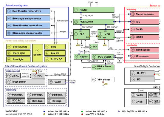
| (r-i.) | Information Groups | Figure 7: sensor and I-SCC subsystem, PLC | Section 4.1.1 |
| (r-ii.) | USV Interaction | Figure 7: I-SCC subsystem | Section 4.1.2 |
| (r-iii.) | marine-grade, industrial components | Table A1 | Section 4.1.3 |
| (r-iv.) | modular and flexible design | Figure 7 | Section 4.1.3 |
| Information Group | Design Result |
|---|---|
| Sailing information | Figure 7: autonomy sensor subsystem |
| Observation information | Figure 7: autonomy and monitoring sensor subsystems |
| Safety and Emergency information | Figure 7: PLC |
| Security information | Figure 7: monitoring sensor subsystem |
| Technical information | Figure 7: PLC |
© 2020 by the authors. Licensee MDPI, Basel, Switzerland. This article is an open access article distributed under the terms and conditions of the Creative Commons Attribution (CC BY) license (http://creativecommons.org/licenses/by/4.0/).
Share and Cite
Peeters, G.; Yayla, G.; Catoor, T.; Van Baelen, S.; Afzal, M.R.; Christofakis, C.; Storms, S.; Boonen, R.; Slaets, P. An Inland Shore Control Centre for Monitoring or Controlling Unmanned Inland Cargo Vessels. J. Mar. Sci. Eng. 2020, 8, 758. https://doi.org/10.3390/jmse8100758
Peeters G, Yayla G, Catoor T, Van Baelen S, Afzal MR, Christofakis C, Storms S, Boonen R, Slaets P. An Inland Shore Control Centre for Monitoring or Controlling Unmanned Inland Cargo Vessels. Journal of Marine Science and Engineering. 2020; 8(10):758. https://doi.org/10.3390/jmse8100758
Chicago/Turabian StylePeeters, Gerben, Gökay Yayla, Tim Catoor, Senne Van Baelen, Muhammad Raheel Afzal, Christos Christofakis, Stijn Storms, René Boonen, and Peter Slaets. 2020. "An Inland Shore Control Centre for Monitoring or Controlling Unmanned Inland Cargo Vessels" Journal of Marine Science and Engineering 8, no. 10: 758. https://doi.org/10.3390/jmse8100758