Article

Free Vibration Analysis of Laminated Functionally Graded Carbon Nanotube-Reinforced Composite Doubly Curved Shallow Shell Panels Using a New Four-Variable Refined Theory

Faculty of Industrial and Civil Engineering, National University of Civil Engineering, Hanoi 100000, Vietnam
*
Author to whom correspondence should be addressed.
J. Compos. Sci. 2019, 3(4), 104; https://doi.org/10.3390/jcs3040104
Submission received: 31 October 2019 / Revised: 25 November 2019 / Accepted: 28 November 2019 / Published: 1 December 2019
(This article belongs to the Special Issue Multifunctional Composites)

Abstract

:
In this paper, a new four-variable refined shell theory is developed for free vibration analysis of multi-layered functionally graded carbon nanotube-reinforced composite (FG-CNTRC) doubly curved shallow shell panels. The theory has only four unknowns and satisfies zero stress conditions at the free surfaces without correction factor. Five different types of carbon nanotube (CNTs) distribution through the thickness of each FG-CNT layer are considered. Governing equations of simply supported doubly curved FG-CNTRC panels are derived from Hamilton’s principle. The resultant eigenvalue system is solved to obtain the frequencies and mode shapes of the anti-symmetric cross-ply laminated panels by using the Navier solution. The numerical results in the comparison examples have proved the accuracy and efficiency of the developed model. Detailed parametric studies have been carried out to reveal the influences of CNTs volume fraction, CNTs distribution, CNTs orientation, dimension ratios and curvature on the free vibration responses of the doubly curved laminated FG-CNTRC panels.

Graphical Abstract

1. Introduction

Functionally graded carbon nanotube-reinforced composites were first proposed by Shen [1] and have been widely accepted as a new advanced material. In functionally graded carbon nanotube-reinforced composite (FG-CNTRC) structures, the CNTs are assumed to be distributed and functionally graded with certain rules along the desired direction to improve the mechanical properties of the structures. Due to the curvature effect, doubly curved shell structures possess increased structural stiffness as compared to flat ones. Therefore, doubly curved shells are often employed to fabricate structural elements of modern constructions made of advanced materials in various engineering disciplines such as aerospace, civil, marine and mechanical engineering. It is thus significant and very meaningful to explore the mechanical response of doubly curved shells made of laminated FG-CNTRC.
Due to its simplicity and effectiveness, the equivalent single-layer model is used for multi-layer composite materials. Among the equivalent single layer models, the model based on the classical theory (CPT) [2] only provides accurate results for the thin shell because it completely neglects the effect of shear deformation. To overcome the limitations of CPT, the model based on the first-order shear deformation theory (FSDT) [3] takes into account the shear deformation effects and provides relatively accurate results for both thin and moderately thick shells, but it has to use shear correction factor. Therefore, the model based on the higher-order shear deformation theory (HSDT) [4,5,6] is often desirable. However, it is not convenient to use HSDT because the equations of motions based on HSDT are complicated and difficult to solve. Therefore, the development of simple HSDT is needed. In addition to these, a four-variable deformation theory [7,8,9,10,11] has been developed and applied recently. In this theory model, the transverse shear stresses are satisfied to be parabolic and to be zero on free surfaces. Furthermore, it has only four unknowns, thus the governing equations can be reduced to four.
Based on the above-mentioned theories, various studies have been done to investigate the bending, buckling and vibration responses of FG-CNTRC shells and panels. Using the third-order shear deformation theory, Mehrabadi and Aragh [12] investigated static behavior of FG-CNTRC cylindrical shells. Aragh et al. [13] and Yas et al. [14] studied free vibration of FG-CNTRC cylindrical panels. Alibeigloo [15] analyzed the free vibration behavior of the FG-CNTRC cylindrical panel embedded in piezoelectric layers based on the three-dimensional theory of elasticity and the state-space technique. Lei et al. [16] presented the first-known dynamic stability of FG-CNTRC cylindrical panels under static and periodic axial force. Rasool el al. [17] analyzed the stress wave propagation of FG-CNTRC cylinders subjected to an impact load by using an element-free method. In [18], Shen and Zhang investigated thermal post-buckling of FG-CNTRC cylindrical shells subjected to a uniform temperature rise. Based on a HSDT with a von Kármán-type of kinematic nonlinearity, Shen [19] presented the thermal post-buckling and torsional post-buckling of FG-CNTRC cylindrical shells. Furthermore, Shen and Xiang also performed research on nonlinear vibration [20], and post-buckling [21] behavior of FG-CNTRC cylindrical shells in the thermal environment. A post-buckling analysis of FG-CNTRC cylindrical panels subjected to axial compression was also presented by Liew et al. [22]. In this study, Liew et al. used a meshless approach and arc-length method combined with the modified Newton–Raphson method to trace the post-buckling path. Using the element-free kp-Ritz method, Lei et al. [23] investigated free vibration of FG-CNTRC rotating cylindrical panels. Based on the generalized differential quadrature method (GDQM)and the finite element (FE) method, Tornabene et al. [24] and Thomas et al. [25], respectively, investigated free vibration of FG-CNT-reinforced laminated composite doubly curved shells.
The purpose of this paper is to develop a new four-variable refined shell theory for free vibration analysis of multi-layered functionally graded carbon nanotube-reinforced composite doubly curved panels. The present theory has only four unknowns but it satisfies the stress-free boundary conditions on the top and bottom surface without using shear correction factors. The distribution of the carbon nanotube (CNT) through the thickness of each layer may be functionally graded or uniformly distributed. The resultant eigenvalue system is solved to obtain the frequencies and mode shapes of the anti-symmetric, cross-ply laminated panels by Navier solution. The accuracy of the presented formulation is investigated by comparing the obtained natural frequencies with existing results in the literature. Also, a novelty parameter study of the laminated FG-CNTRC doubly-curved panels of which the geometrical parameters, CNTs distributions, the volume fraction of CNTs, as well as the number of layers are also reported in detail.

2. Theoretical Formulations

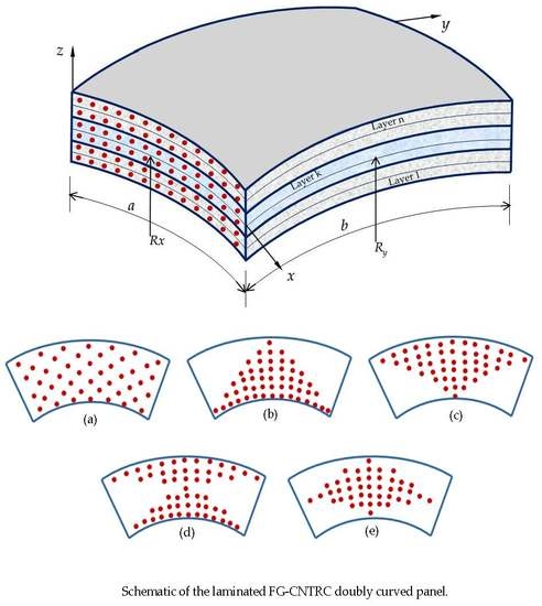
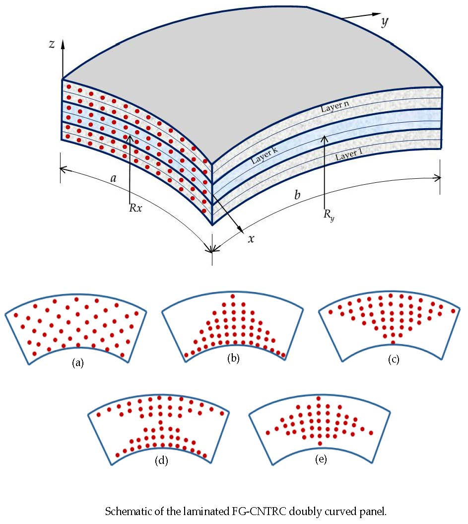
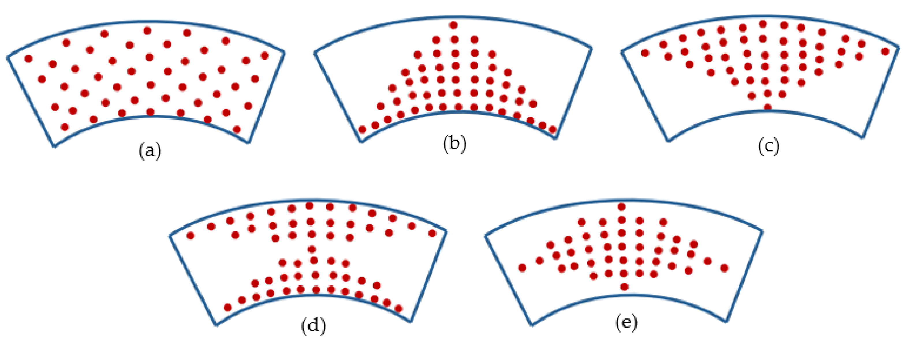
2.1. Description of the Model

As shown in Figure 1, a doubly curved FG-CNTRC shell panel in the orthogonal curvilinear coordinate system (x, y, z) is considered as the modal analysis. The panel has curvilinear length a in the x-direction, curvilinear width b in the y-direction, thickness h in the z-direction. In the middle surface of the panel, the principal radii of curvature, denoted by Rx and Ry, are assumed as constants. This results in unit Lamé parameters. Here, four special kinds of the doubly curved shell panels are investigated such as plate (PLA, Rx = Ry = ∞), cylindrical (CYL) panel (Rx = R and Ry = ∞), spherical (SPH) panel (Rx = Ry), and hyperbolic paraboloid (HPR) panel (Rx = −Ry).

2.2. Material Properties of Functionally Graded Carbon Nanotube-Reinforced Composite

In the present study, the lamina is assumed to be perfectly bonded at layer interfaces. As shown in Figure 2, five types of functionally graded distributions of CNTs in each layer are taken into consideration, named as UD, FG-A, FG-V, FG-X and FG-O.
For these cases, the CNT volume fractions are given as [26]:
U D : V C N T ( z ) = V C N T * ; F G V :   V C N T ( z ) = 2 V C N T * z z k z k + 1 z k ; F G A :   V C N T ( z ) = 2 V C N T * z k + 1 z z k + 1 z k ; F G O :   V C N T ( z ) = 2 V C N T * ( 1 | 2 z z k z k + 1 | z k + 1 z k ) ; F G X :   V C N T ( z ) = 2 V C N T * ( | 2 z z k z k + 1 | z k + 1 z k )
where z k and z k + 1 are the coordinates of the k-th layer to the reference plane (z = 0). V C N T * is the given volume fraction of CNTs and can be calculated as:
V C N T * = w C N T w C N T + ( ρ C N T / ρ m ) ( ρ C N T / ρ m ) w C N T
in which, w C N T is the mass fraction of the carbon nanotube, ρ m and ρ C N T are mass densities of the matrix and the CNT, respectively. The effective material properties of FG-CNTRC of each layer can be expressed by the extended rule of the mixture as follows [27]:
E 11 ( z ) = η 1 V C N T ( z ) E 11 C N T + V m ( z ) E m η 2 E 22 ( z ) = V C N T ( z ) E 22 C N T + V m ( z ) E m ; η 3 G 12 ( z ) = V C N T ( z ) G 12 C N T + V m ( z ) G m ; ρ ( z ) = V C N T ( z ) ρ C N T + V m ( z ) ρ m ; ν 12 = V C N T * ν 12 C N T + V m ( z ) ν m
where E 11 C N T ,   E 22 C N T ,   E m and G 12 C N T ,   G m are the Young’s moduli and shear modulus of CNT and matrix; η 1 , η 2 and η 3 are CNT/matrix efficiency parameters; V C N T ( z ) and V m ( z ) are volume fractions of CNT and matrix, and are related by V C N T ( z ) + V m ( z ) = 1 ; v 12 C N T and v m are Poisson’s ratio of CNT and matrix.

2.3. Kinematic Relations

This work aims to establish a new shear deformation shell theory. The main idea of the present theory comes from the four-variable refined theory [8,9,11,28,29]. According to assumptions of various four-variable refined theories, the transverse displacement w is partitioned into the bending component w b and shear component w s , the in-plane displacements u and v are also partitioned into the extension component u 0 ,   v 0 , the bending component u b ,   v b , and shear component u s ,   v s . Therefore, the displacement field in the doubly curved shell space can be expressed as follows:
u ( x , y , z , t ) = ( 1 + z R x ) u 0 ( x , y , t ) z w b ( x , y , t ) x f ( z ) w s ( x , y , t ) x v ( x , y , z , t ) = ( 1 + z R y ) v 0 ( x , y , t ) z w b ( x , y , t ) y f ( z ) w s ( x , y , t ) y w ( x , y , z , t ) = w b ( x , y , t ) + w s ( x , y , t )
where u 0 ,   v 0 denote the displacements along x and y coordinate directions of the corresponding point on the reference surface; w b and w s are the bending and shear components of the transverse displacement, respectively; f ( z ) represents shape function determining the distribution of the transverse shear strains and stresses along the thickness. By the same methodology, in the previous study [29], we proposed a new shape function f ( z ) as follows:
f ( z ) = z [ 1 8 + 3 2 ( z h ) 2 ]
Detail steps to construct this shape function for shell panels are listed in Appendix A.
The strains associated with the displacement field in Equation (4) are:
ε x x = 1 1 + z / R x [ ε x 0 + z κ x b + f ( z ) κ x s ] ; ε y y = 1 1 + z / R y [ ε y 0 + z κ y b + f ( z ) κ y s ] ; γ x y = 1 1 + z / R x [ γ x y 0 + z κ x y b + f ( z ) κ x y s ] + 1 1 + z / R y [ γ y x 0 + z κ y x b + f ( z ) κ y x s ] ; γ x z = 1 1 + z / R x g ( z ) γ x z s ;   γ y z = 1 1 + z / R y g ( z ) γ yz s
where:
ε x 0 = ( u 0 x + w b R x + w s R x ) ; γ x y 0 = v 0 x ; ε y 0 = ( v 0 y + w b R y + w s R y ) ; γ yx 0 = u 0 y ; k x b = ( 1 R x u 0 x w b 2 x 2 ) ; κ y b = ( 1 R y v 0 y w b 2 y 2 ) ; κ x y b = ( 1 R y v 0 x w b 2 x y ) ;   κ yx b = ( 1 R x u 0 y w b 2 x y ) ; k x s = 2 w s x 2 ;   k y s = 2 w s y 2 ;   κ x y s = 2 w s x y ;   κ y x s = 2 w s x y ; γ x z = 1 1 + z / R x g ( z ) w s x ;   g ( z ) = ( 1 f ( z ) ) ; γ y z = 1 1 + z / R x g ( z ) w s y
The constitutive relation for an individual layer can be determined by the generalized Hooke’s law, namely [30,31]:
{ σ x x k σ y y k τ y z k τ x z k τ x y k } = [ Q ¯ 11 k Q ¯ 11 k 0 0 Q ¯ 16 k Q ¯ 12 k Q ¯ 22 k 0 0 Q ¯ 26 k 0 0 Q ¯ 44 k Q ¯ 45 k 0 0 0 Q ¯ 45 k Q ¯ 55 k 0 Q ¯ 16 k Q ¯ 26 k 0 0 Q ¯ 66 k ] { ε x x ε y y γ y z γ x z γ x y }
where Q ¯ i j k are the transformed material constraints expressed in terms of material constants:
Q ¯ 11 k = Q 11 cos 4 θ k + 2 ( Q 12 + 2 Q 66 ) sin 2 θ k cos 2 θ k + Q 22 sin 4 θ k ; Q ¯ 12 k = ( Q 11 + Q 22 4 Q 66 ) sin 2 θ k cos 2 θ k + Q 12 ( sin 4 θ k + cos 4 θ k ) ; Q ¯ 22 k = Q 11 sin 4 θ k + 2 ( Q 12 + 2 Q 66 ) sin 2 θ k cos 2 θ k + Q 22 cos 4 θ k ; Q ¯ 16 k = ( Q 11 Q 12 2 Q 66 ) sin θ k cos 3 θ k + ( Q 12 Q 22 + 2 Q 66 ) sin 3 θ k cos θ k ; Q ¯ 26 k = ( Q 11 Q 12 2 Q 66 ) sin 3 θ k cos θ k + ( Q 12 Q 22 + 2 Q 66 ) sin θ k cos 3 θ k ; Q ¯ 66 k = ( Q 11 + Q 22 2 Q 12 2 Q 66 ) sin 2 θ k cos 2 θ k + Q 66 ( sin 4 θ k + cos 4 θ k ) ; Q ¯ 44 k = Q 44 cos 2 θ k + Q 55 sin 2 θ k ; Q ¯ 45 k = ( Q 55 Q 44 ) cos θ k sin θ k ; Q ¯ 55 k = Q 55 cos 2 θ k + Q 44 sin 2 θ k .
in which, Q i j are the plane stress-reduced stiffnesses defined in terms of the engineering constants in the material axes of the layer. For each CNT layer:
Q 11 = E 11 ( z ) 1 ν 12 ν 21 ;   Q 12 = ν 12 E 22 ( z ) 1 ν 12 ν 21 ;   Q 22 = E 22 ( z ) 1 ν 12 ν 21 ; Q 44 = G 23 ( z ) ;   Q 55 = G 13 ( z ) ;   Q 66 = G 12 ( z )

2.4. Governing Equations

Hamilton’s principle is used herein to derive the equations of motion. In the absence of external forces, the principle can be stated in the analytical form as [32]:
t 1 t 2 ( δ U δ K ) d t = 0
where δU is the variation of the strain energy, δK is the variation of the kinetic energy, t 1 and t 2 are arbitrary time variables. The strain energy of the plate can be calculated as:
U = 1 2 0 a 0 b h / 2 h / 2 ( σ x x ε x x + σ y y ε y y + τ x y γ x y + τ x z γ x z + τ y z γ y z ) ( 1 + z R x ) ( 1 + z R y ) d z dydx = 1 2 0 a 0 b ( N x x ε x x 0 + N y y ε y y 0 + N x y γ x y 0 + N y x γ y x 0 + M x x b κ x x b + M y y b κ y y b + M x y b κ x y b + M y x b κ y x b + M x x s κ x x s + M y y s κ y y s + M x y s κ x y s + M y x s κ y x s + Q y s γ y z s + Q x s γ x z s ) d x d y
where stress resultants (N, M and Q) are defined by:
{ N x x N x y Q xs } = k = 1 n z k z k + 1 ( 1 + z R y ) { σ x x k σ x y k τ x z k } d z ;   { N y y N y x Q ys } = k = 1 n z k z k + 1 ( 1 + z R x ) { σ y y k σ y x k τ yz k } d z ; { M x x b M x y b } = k = 1 n z k z k + 1 ( 1 + z R y ) { σ x x k σ x y k } z d z ;   { M y y b M y x b } = k = 1 n z k z k + 1 ( 1 + z R x ) { σ y y k σ y x k } z d z ; { M x x s M x y s } = k = 1 n z k z k + 1 ( 1 + z R y ) { σ x x k σ x y k } f ( z ) d z ; { M y y s M y x s } = k = 1 n z k z k + 1 ( 1 + z R x ) { σ y y k σ y x k } f ( z ) d z .
Based on the constitutive relations (8), strain-displacement relation (6) and displacement field (4), the force and moment resultants can be rewritten in terms of displacement components as:
{ N x x N y y N x y N y x M x x b M y y b M x y b M y x b M x x s M y y s M x y s M y x s } = [ A ¯ 11 A 12 A ¯ 16 A 16 B ¯ 11 B 12 B ¯ 16 B 16 B ¯ 11 s B 12 s B ¯ 16 s B 16 s A 12 A ^ 22 A 26 A ^ 26 B 12 B ^ 22 B 26 B ^ 26 B 12 s B ^ 22 s B 26 s B ^ 26 s A ¯ 16 A 26 A ¯ 66 A 66 B ¯ 16 B 26 B ¯ 66 B 66 B ¯ 16 s B 26 s B ¯ 66 B 66 s A 16 A ^ 26 A 66 A ^ 66 B 16 B ^ 26 B 66 B ^ 66 B 16 s B ^ 26 s B 66 s B ^ 66 s B ¯ 11 B 12 B ¯ 16 B 16 D ¯ 11 D 12 D ¯ 16 D 16 D ¯ 11 s D 12 s D ¯ 16 s D 16 s B 12 B ^ 22 B 26 B ^ 26 D 12 D ^ 22 D 26 D ^ 26 D 12 s D ^ 22 s D 26 s D ^ 26 s B ¯ 16 B 26 B ¯ 66 B 66 D ¯ 16 D 26 D ¯ 66 D 66 D ¯ 16 s D 26 s D ¯ 66 s D 66 s B 16 B ^ 26 B 66 B ^ 66 D 16 D ^ 26 D 66 D ^ 66 D 16 s D ^ 26 s D 66 s D ^ 66 s B ¯ 11 s B 12 s B ¯ 16 s B 16 s D ¯ 11 s D 12 s D ¯ 16 s D 16 s E ¯ 11 s E 12 s E ¯ 16 s E 16 s B 12 s B ^ 22 s B 26 s B ^ 26 s D 12 s D ^ 22 s D 26 s D ^ 26 s E 12 s E ^ 22 s E 26 s E ^ 26 s B ¯ 16 s B 26 s B ¯ 66 B 66 s D ¯ 16 s D 26 s D ¯ 66 s D 66 s E ¯ 16 s E 26 s E ¯ 66 s E 26 s B 16 s B ^ 26 s B 66 s B ^ 66 s D 16 s D ^ 26 s D 66 s D ^ 66 s E 16 s E ^ 26 s E 26 s E ^ 66 s ] { ε x x 0 ε y y 0 γ x y 0 γ y x 0 κ x x b κ y y b κ x y b κ y x b κ x x s κ y y s κ x y s κ y x s }
{ Q ys Q xs } = [ A ^ 44 s A 45 s A 45 s A ¯ 55 s ] { γ y z s γ x z s }
in which:
{ A ij , B ij , D ij , B ij s , D ij s , A ij s } = 1 N z k z + 1 Q ¯ ij ( k ) { 1 , z , z 2 , f ( z ) , z f ( z ) , g 2 ( z ) } d z ; { A ¯ ij , B ¯ ij , D ¯ ij , B ¯ ij s , D ¯ ij s , A ¯ ij s } = { A ijx , B ijx , D ijx , B ijx s , D ijx s , A ijx s } + { B ijx , D ijx , E ijx , D ijx s , E ijx s , AA ijx s } R y ; { A ijx , B ijx , D ijx , E ijx , B ijx s , D ijx s , E ijx s , A ijx s , A A ijx s } = 1 N z k z + 1 Q ¯ ij ( k ) { 1 , z , z 2 , z 3 , f ( z ) , z f ( z ) , z 2 f ( z ) , g ( z ) , z g ( z ) } 1 + z / R x d z { A ^ ij , B ^ ij , D ^ ij , B ^ ij s , D ^ ij s , A ^ ij s } = { A ijy , B ijy , D ijy , B ijy s , D ijy s , A ijy s } + { B ijy , D ijy , E ijy , D ijy s , E ijy s , A A ijy s } R x { A ijy , B ijy , D ijy , E ijy , B ijy s , D ijy s , E ijy s , A ijy s , A A ijy s } = 1 N z k z + 1 Q ¯ ij ( k ) { 1 , z , z 2 , z 3 , f ( z ) , z f ( z ) , z 2 f ( z ) , g ( z ) , z g ( z ) } 1 + z / R y d z
The variation of the kinetic energy of the panel can be written as:
K = 1 2 0 a 0 b h / 2 h / 2 ρ ( z ) ( u ˙ 2 + v ˙ 2 + w ˙ 2 ) ( 1 + z R x ) ( 1 + z R y ) d z dydx = 1 2 0 a 0 b ( ( I ¯ 0 u ˙ 0 + I ¯ 2 ϕ ˙ x b 2 + K ¯ 1 ϕ ˙ x s 2 + 2 I ¯ 1 u ˙ 0 ϕ ˙ x b + 2 J ¯ 1 u ˙ 0 ϕ ˙ x s + 2 J ¯ 2 ϕ ˙ x b ϕ ˙ x s + I ¯ 0 v ˙ 0 2 + I ¯ 2 ϕ ˙ y b 2 + K ¯ 1 ϕ ˙ ys 2 + 2 I ¯ 1 v ˙ 0 ϕ ˙ y b + 2 J ¯ 1 v ˙ 0 ϕ ˙ ys + 2 J ¯ 2 ϕ ˙ y b ϕ ˙ ys + I ¯ 0 ( w ˙ b 2 + w ˙ 2 s + 2 w ˙ b w ˙ s ) ) d y d x
where:
ϕ x b = ( u 0 R x w b x ) ;   ϕ xs = w s x ;   ϕ y b = ( v 0 R y w b y ) ;   ϕ ys = w s y
and ρ ( z ) is the mass density, and the mass moments of inertia I ¯ i   ( i   =   0 ,   1 ,   2 ) are defined as [30,33]:
I ¯ i = I i + I i + 1 ( 1 R x + 1 R y ) + I i + 2 R x R y ; { I 0 , I 1 , I 2 , I 3 } = k = 1 N z k z + 1 ρ ( z ) { 1 , z , z 2 , z 3 } d z ; J ¯ i = f ( z ) I ¯ i 1 ;   K ¯ 1 = f 2 ( z ) I ¯ 0
Substituting the expressions of U and K from Equation (12) and Equation (17) into Equation (11), and by performing some mathematical manipulations, the equations of motion of the shell panel are obtained as follows:
0 = A [ [ N x x x + N yx y + Q x b R x I ¯ 0 u ¨ 0 I ¯ 1 ( u ¨ 0 R x w ¨ b x ) + J ¯ 1 w ¨ s x ] δ u 0 [ N y y y + N yx x + Q y b R y I ¯ 0 v ¨ 0 I ¯ 1 ( v ¨ 0 R y w ¨ b y ) + J ¯ 1 w ¨ s y ] δ v 0 [ N x x R x N y y R y + Q x b x + Q y b y I ¯ 0 ( w ¨ b + w ¨ s ) ] δ w b [ N x x R x N y y R y + Q x s x + Q y s y I ¯ 0 ( w ¨ b + w ¨ s ) ] δ w s ] d A + 0 b [ Γ x ] 0 a d y + 0 a [ Γ y ] 0 b d x
where:
Q x b = M x x b x + M yx b y ( I ¯ 1 + I ¯ 2 R x ) u ¨ 0 + I ¯ 2 w ¨ b x + J ¯ 2 w ¨ s x Q y b = M y y b y + M xy b x ( I ¯ 1 + I ¯ 2 R y ) v ¨ 0 + I ¯ 2 w ¨ b y + J ¯ 2 w ¨ s y Q ¯ x s = M x x s x + M yx s y + Q x s ( J ¯ 1 + J ¯ 2 R x ) u ¨ 0 + J ¯ 2 w ¨ b x + K ¯ 1 w ¨ s x Q ¯ y s = M y y s y + M x y s x + Q y s ( J ¯ 1 + J ¯ 2 R y ) v ¨ 0 + J ¯ 2 w ¨ b x + K ¯ 1 w ¨ s y
and Γ x ,   Γ y are boundary expressions:
Γ x = N ¯ x x δ u 0 + N ¯ x y δ v 0 + Q x b δ w b + Q ¯ x s δ w s + M x x b δ ϕ ˜ x b + M x y b δ ϕ ˜ y b + M x x s δ ϕ x s + M x y s δ ϕ y s Γ y = N ¯ y y δ v 0 + N ¯ y x δ u 0 + Q y b δ w b + Q ¯ y s δ w s + M y y b δ ϕ ˜ y b + M yx b δ ϕ ˜ x b + M y y s δ ϕ y s + M yx s δ ϕ x s
in which:
N ¯ x x = ( N x x M x x b R x ) ;   N ¯ x y = ( N x y M x y b R y ) ;   N ¯ y y = ( N y y M y y b R y ) ;   N ¯ y x = ( N y x M y x b R x ) ;   ϕ ˜ x b = w b x ;   ϕ xs = w s x ;   ϕ ˜ y b = w b y ;   ϕ ys = w s y
By setting the coefficients of the virtual displacements δ u 0 , δ v 0 ,   δ w b , δ w s to zeros, the governing equations are obtained as follows:
δ u 0 : N x x x + N yx y + Q x b R x = I ¯ 0 u ¨ 0 + I ¯ 1 ( u ¨ 0 R x w ¨ b y ) J ¯ 1 w ¨ s x δ v 0 : N y y y + N yx x + Q y b R y = I ¯ 0 v ¨ 0 + I ¯ 1 ( v ¨ 0 R y w ¨ b y ) J ¯ 1 w ¨ s y δ w b : N x x R x + N y y R y Q x b x Q y b y = I ¯ 0 ( w ¨ b + w ¨ s ) δ w s : N x x R x + N y y R y Q x s x Q y s y = I ¯ 0 ( w ¨ b + w ¨ s )

2.5. Solution Procedure

The Navier method is employed to formulate the closed-form solution for vibration problems of simply supported anti-symmetric cross-ply laminated FG-CNTRC panels. The simply supported boundary conditions on all four edges can be considered as:
v 0 = w b = w s = w b , y = w s , y = N x x = M x x b = M x x s = 0   at   x   = 0   and   x   = a
u 0 = w b = w s = w b , x = w s , x = N y y = M y y b = M y y s = 0   at   y   =   0   and   y   =   b
These boundary conditions are exactly satisfied by the following double Fourier series forms:
u ( x , y , t ) = m = 1 n = 1 U m n e i ω t cos α m x sin β n y ; v ( x , y , t ) = m = 1 n = 1 V m n e i ω t sin α m x cos β n y ; w b ( x , y , t ) = m = 1 n = 1 W b m n e i ω t sin α m x sin β n y ; w s ( x , y , t ) = m = 1 n = 1 W s m n e i ω t sin α m x sin β n y .
where ( U mn , V mn , W b m n , W s m n ) are unknown coefficients to be determined, ω is the circular frequency of vibration, and i = 1 ,   α m   =   m π / a ,   β n   =   n π / b and m, n denote the number of haft-waves in the x and y directions, respectively.
Substituting the admissible displacement functions of Equation (27) into the equation of motion, Equation (20), one obtains the analytical solution in the following matrix form:
( [ s 11 s 12 s 13 s 14 s 12 s 22 s 23 s 24 s 13 s 23 s 33 s 34 s 14 s 24 s 34 s 44 ] ω 2 [ m 11 m 12 m 13 m 14 m 12 m 22 m 23 m 24 m 13 m 23 m 33 m 34 m 14 m 24 m 34 m 44 ] ) { U m n V m n W b m n W s m n } = { 0 0 0 0 }
where the matrix elements of Equation (28) are given in the Appendix B.

3. Numerical Results and Discussions

In this section, several examples are presented and discussed to verify the accuracy and efficiency of the proposed theory in free vibration analysis of simply supported FG-CNTRC doubly-curved panels. Furthermore, the effects of volume fraction of CNTs, distribution type of CNTs, number of layers, CNT fiber orientation and geometrical parameters on the natural frequencies of panels are also investigated in detail. The material properties for the matrix and CNT are given in Table 1 [34,35]. Also, the CNT efficiency parameters η j (j = 1,2,3) associated with a given volume fraction V C N T * are: η 1 = 0.149 and η 2 = η 3 = 0.934 for the case of V C N T * = 0.11 ; η 1 = 0.150 and η 2 = η 3 = 0.941 for the case of V C N T * = 0.14 ;   η 1 = 0.149 and η 2 = η 3 = 1.381 for the case of V C N T * = 0.17 .

3.1. Comparison Studies

To verify the reliability and accuracy of the present model, several comparison studies were carried out with the results of the previous literature [34,35].

Example 1: Free Vibration of the Simply Supported Doubly Curved FG-CNTRC Panels

Free vibration of the simply supported doubly curved single-layered FG-CNTRC panels is further analyzed for the comparison of the results obtained from the present formulation with the existing results developed by Pouresmaeeli and Fazelzadeh [34] based on FSDT formulations. The geometrical dimensions of the panels are taken as a/b = 1 and a/h = 20. Values of material parameters are listed in Table 1. From the results presented in Table 2, it is observed that the values of the fundamental frequency for plates, spherical, cylindrical, and hyperbolic paraboloid panels have excellent agreement with the available data.

3.2. Parametric Studies

In this section, some new results for free vibration of the anti-symmetric cross-ply laminated FG-CNTRC doubly curved shell panels are investigated with respect to FG-CNTRC parameters, curvature, R x / R y ratio, aspect a/b ratio, and number of layers. The material properties for the matrix and CNT are shown in Table 1.

3.2.1. Effect of FG-CNTRC Parameters

To understand the effect of FG-CNTRC parameters on the free vibration response of different shell panels, non-dimensional frequencies ω ¯ of anti-symmetric cross-ply laminated FG-CNTRC doubly curved shell panels with different CNT distribution, CNT volume fraction, and number of CNT layers are examined.
It is observed from Table 3, that the FG-X panels have the highest value of frequency, whereas, the FG-O panels have the lowest one. Therefore, it can be concluded that the type of CNT distribution has a remarkable influence on the stiffness of the FG-CNTRC shell panels. In detail, the CNTs distributed close to the top and bottom surfaces of each FG-CNTRC layer are more efficient than those distributed near the mid-plane of each FG-CNTRC layer in increasing the stiffness of the laminated FG-CNTRC shell panels. This is compatible with conclusions in previous studies in the literature. According to the detailed results, the values of ω ¯ can be increased by more than 24% with only 6% increasing CNT volume fraction V C N T * for any other parameters. Thus, by adjusting a small amount of CNT volume, the desired stiffness of the FG-CNTRC panels can be achieved. Table 3 also reveals that the SHP panel has the highest value of ω ¯ while the HPR panel has the lowest one. This is because HPR has both sagging and hogging curvature along the two directions, neutralizing the effect of each other, while SHP does not. Table 3, once again confirms the accuracy of the present model by comparing the non-dimensional frequencies of the FG-CNTRC plates with the results of Wang [35].

3.2.2. Effect of Curvature

Two forms of doubly curved shell panels (SPH and HPR) with a/b = 1, a/h = 20, R x = R y = R , (0/90)5, V C N T * = 0.17 were considered, to study the effect of curvature on the non-dimensional frequencies ω ¯ . The results are shown in the Figure 3a,b. These figures indicate that at the small value of R/a, the SHP panels have a much higher non-dimensional frequency than HPR panels. The non-dimensional frequencies of the SHP panels decrease, while those of HPR panels increase with the increase of R/a ratio from one to a specific value. After this value, the non-dimensional frequencies of both SHP and HPR panels have approximate values and seem to be unchanged.

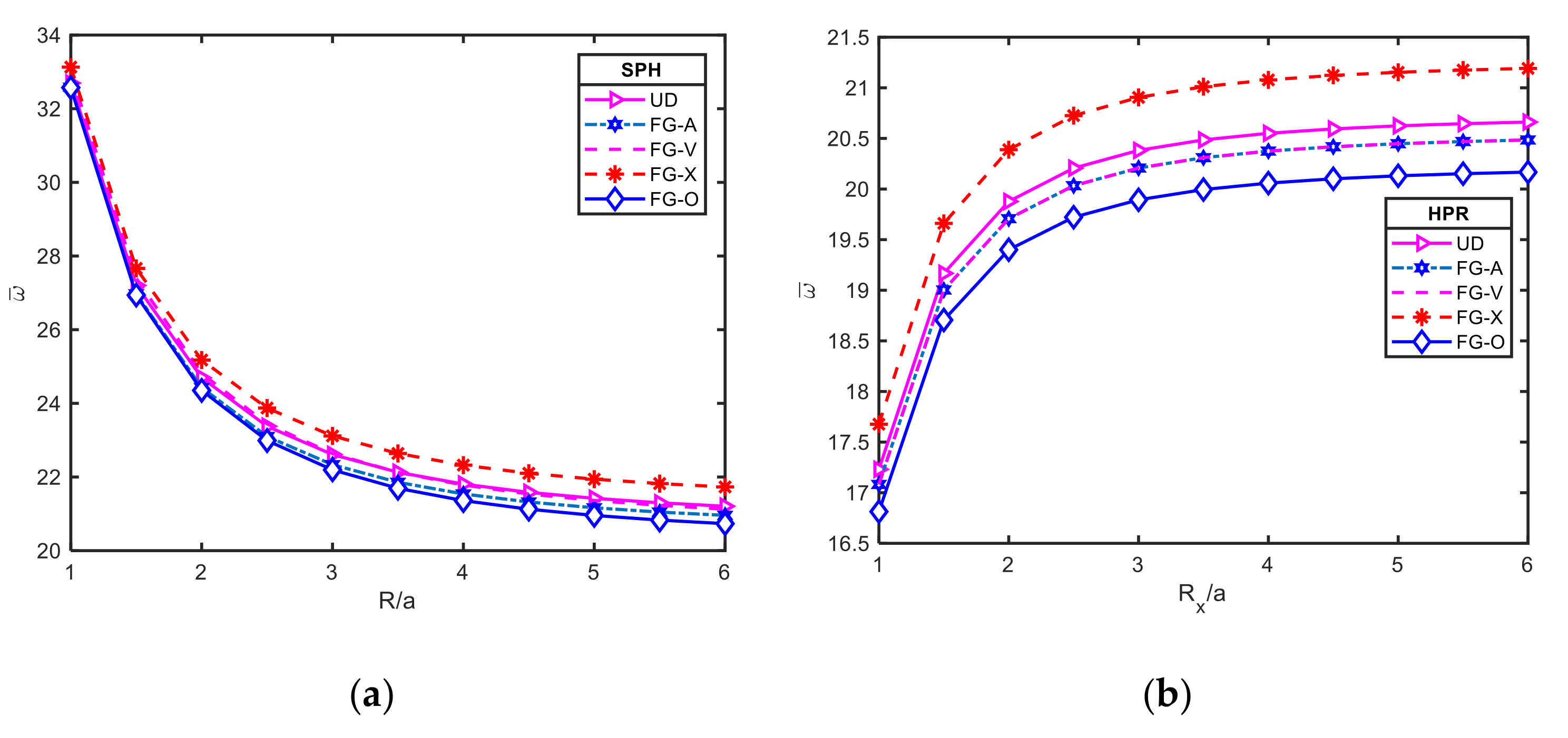
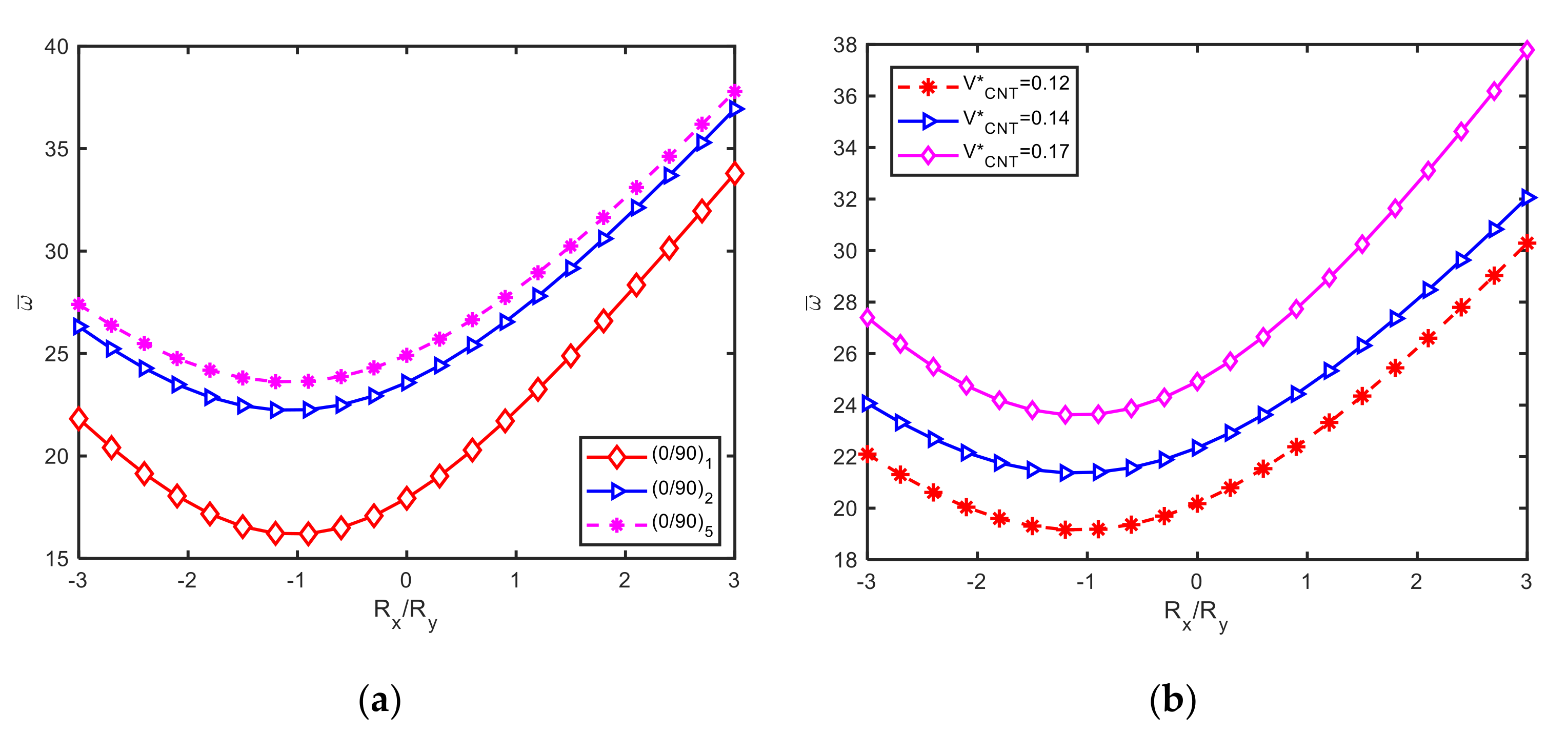
3.2.3. Effect of Curvature Ratio

The effect of curvature ratio R x / R y on non-dimension frequency of the panels is investigated in this subsection. The geometrical dimensions of the panels are taken as a/b = 1, a/h = 20, Rx/a = 5. It can be seen from Figure 4a,b, that the non-dimension frequencies of panels decrease with the increase of curvature ratio from −3 to −1, and increase with the value of curvature ratio bigger than −1 for different numbers of layers and different CNT volume fractions. Moreover, the values of ω ¯ are at minimum when R x / R y = 1 shows that the curvature effect can be suppressed if the shell panels have both negative and positive curvature.

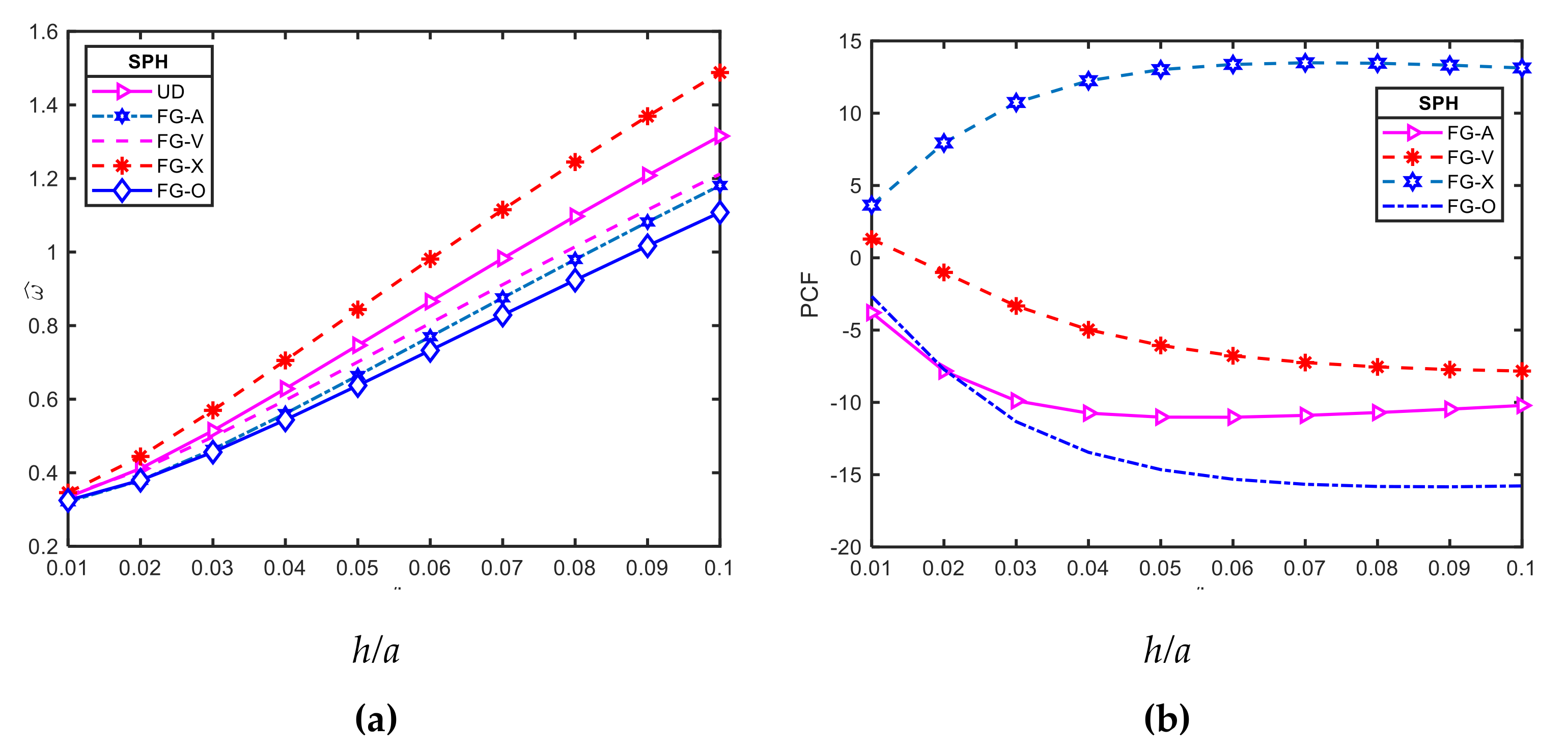
3.2.4. Effect of Thickness Ratio

The SPH shell panel was chosen to study the effect of thickness on the free vibration response of the FG-CNTRC doubly curved shell panel. For this purpose, another non-dimensional frequency is defined as [34]:
ω ^ = ω a ρ m E m
P C F = ( ω ^ F G ω ^ U D ω ^ U D ) × 100
The effect of thickness ratio, h/a, on the non-dimensional frequency of the FG-CNTRC panels is shown in Figure 5. This figure indicates that with all types of CNT distribution, the panels become stiffer with the increase of the thickness ratio, as a result, the non-dimensional frequency of the FG-CNTRC panels increase. Besides, the influence of the thickness ratio, h/a, on the percentage change of frequency (PCF) of the SHP panel is depicted in Figure 5b. It is observed that FG-X panels show positive effectiveness while other FG-CNTRC panels show the negative effects concerning uniformly distribution (UD) panels. The highest percentage change of frequency of an FG-X panel and FG-O panel are about 14.5% and −15.2%, respectively.

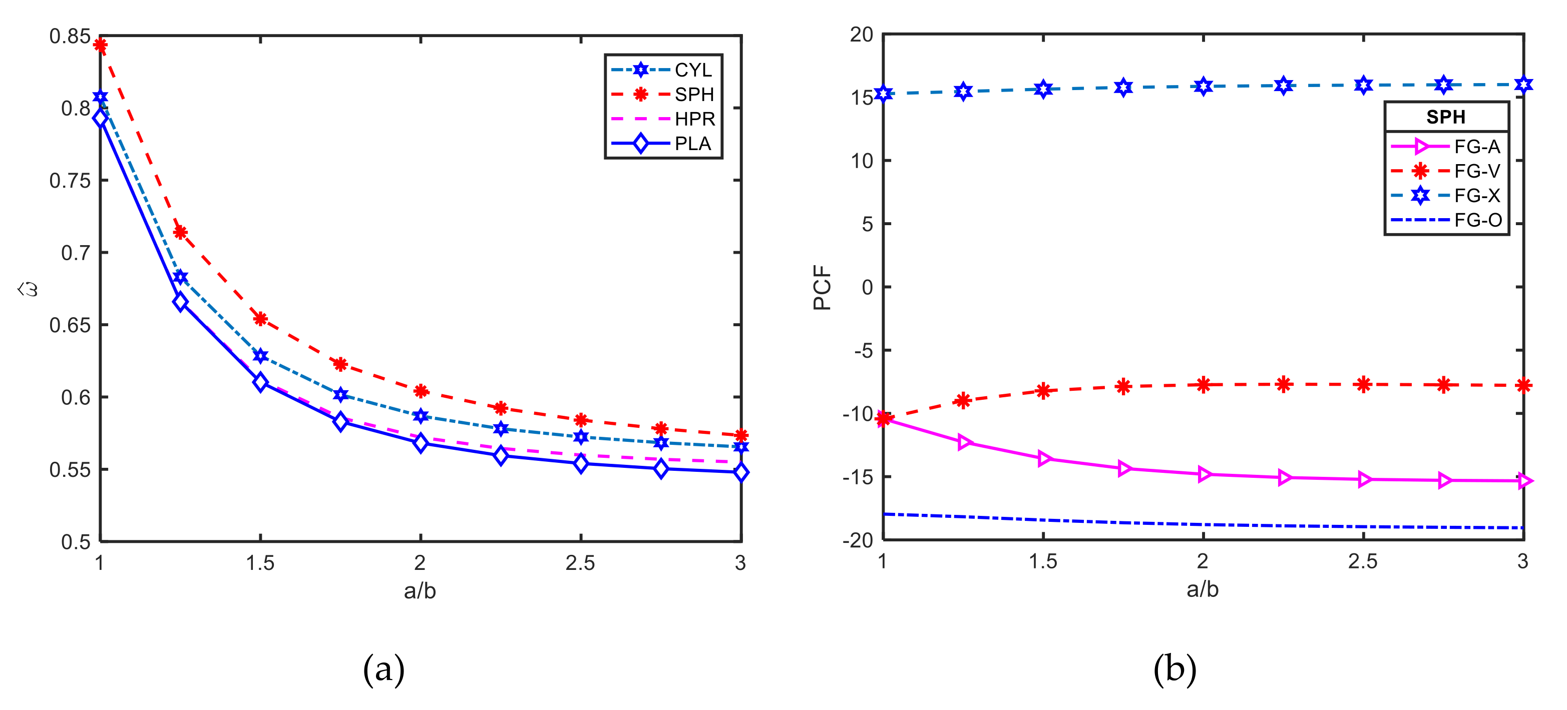
3.2.5. Effect of Aspect Ratio

Figure 6a,b show the effects of the aspect ratio (a/b) on the vibration of FG-CNTRC. Here, we take a/b = 1; R x = R y = R ; R / a = 5 ; V C N T * = 0.17 and (0/90).
Figure 6a reveals that the non-dimensional frequencies of all four types of doubly curved panels decrease uniformly by increasing aspect ratio. In other words, the stiffness of doubly curved panels will be reduced as the aspect ratio increases. Figure 6a states that the PCF of the FG-CNTRC panels remains unchanged with the increase of aspect ratio.

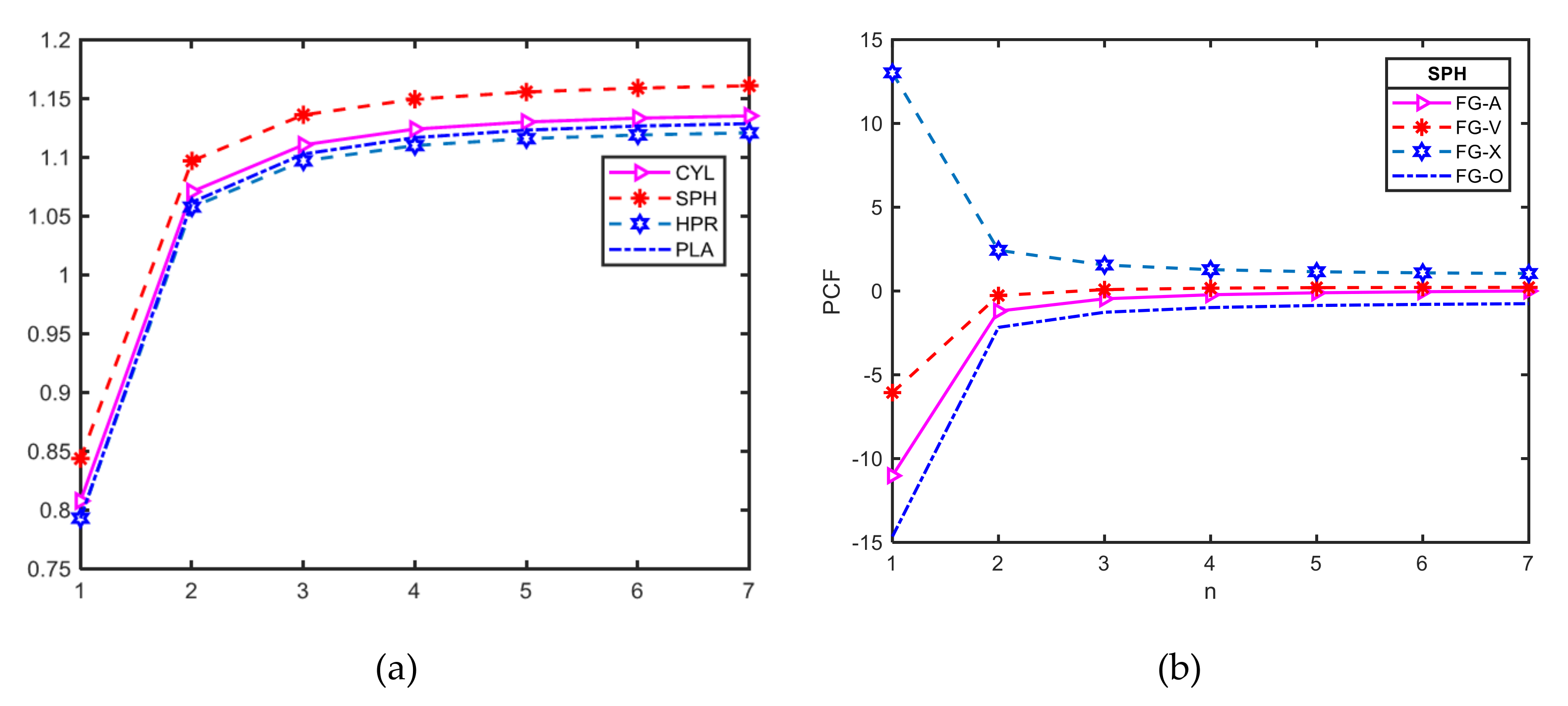
3.2.6. Effect of Number of Layers

The influence of number of layers (n is a couple of layers (0/90)) on ω ^ , and PCF are depicted in Figure 7a,b, respectively. Here, the geometrical dimensions of the panels are taken as a/b = 1, a/h = 20, R x = R y = R , and V C N T * = 0.17 , FG-X, (0/90)n. As the Figures show, with a fixed value of total thickness, the non-dimensional frequencies and the percentage change of frequency of laminated FG-CNTRC panels are strongly affected by the number of layers, changing from one layer to two layers. However, these two dimensionless parameters vary very slightly for the number of layers greater than three. This is compatible with the investigations of Reddy [31], for conventional fiber reinforced composites.

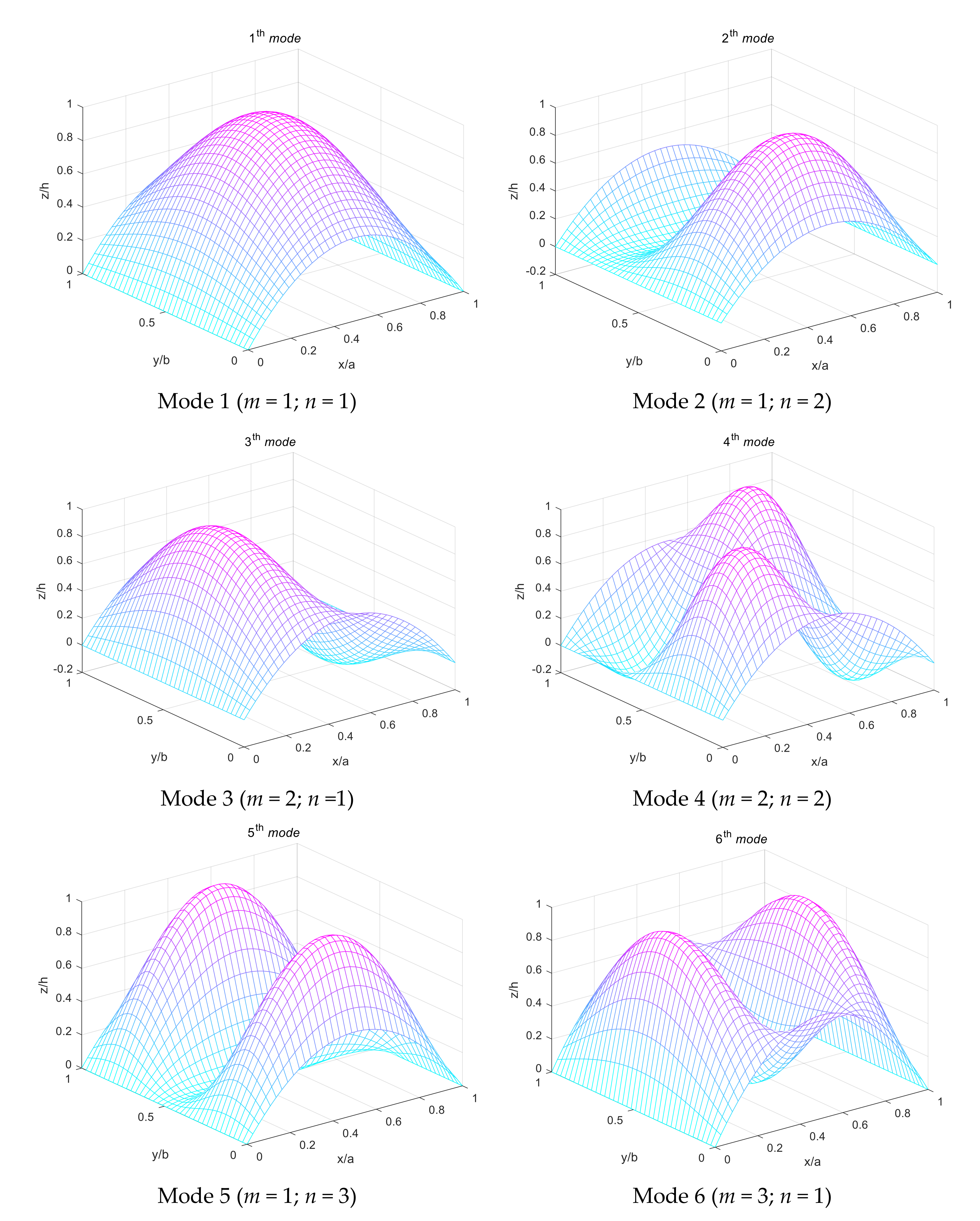
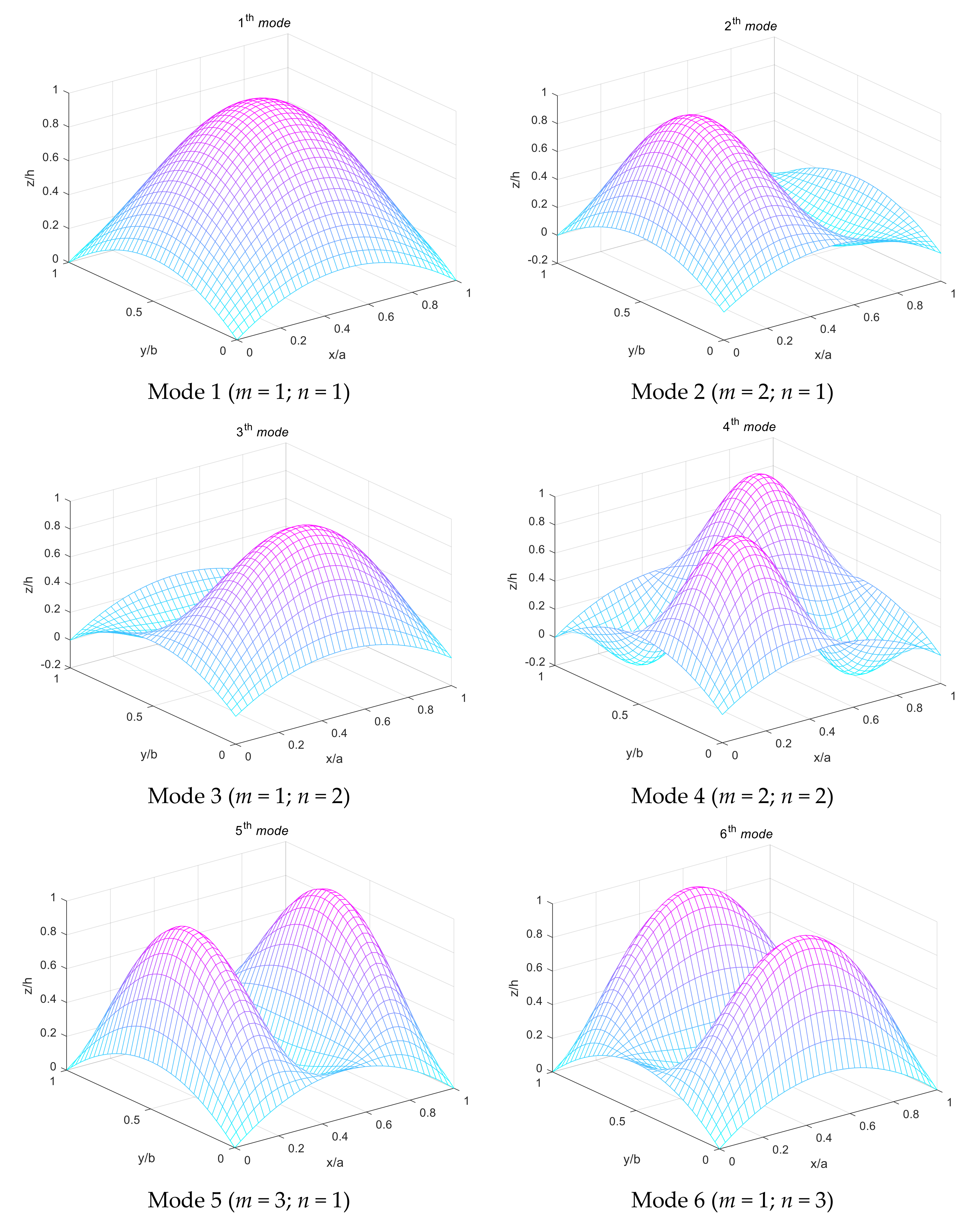
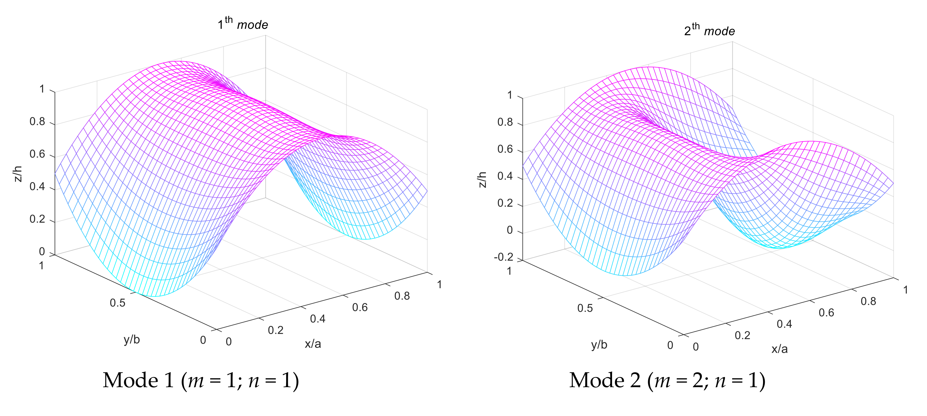
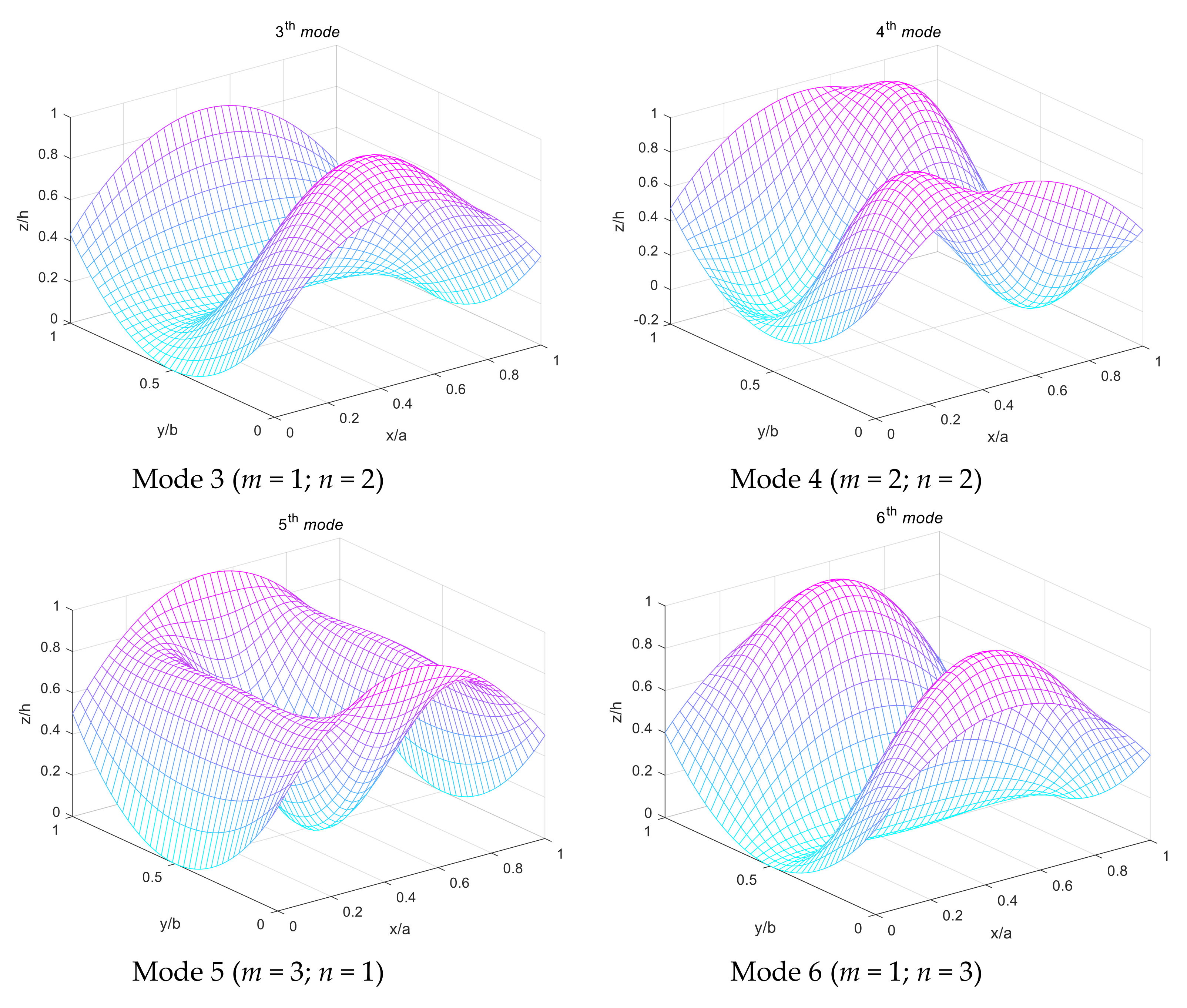
3.2.7. Effect of Different Wave Numbers

Table 4 listed non-dimensional frequencies for two-layered (0/90) FG-CNTRC doubly curved shell panels (a/b = 1; R/a = 5, a/h = 50, FG-X, V C N T * = 0.17 ) for different wave numbers. It can be seen that at the small value of wave numbers (n, m) the SPH panels have highest non-dimensional frequencies while the HPR panels have lowest ones. However, it also can be seen that the non-dimensional frequencies of all three types of doubly curved panels will approximately have more wave numbers.
Figure 8, Figure 9 and Figure 10 depict the first six mode shapes of the simply supported laminated FG-CNTRC CYL, SPH and HPR shell panels, respectively. Geometric characteristics of the panels are a/b = 1, R/a = 5 and a/h = 50. Type of CNT distribution is FG-X and volume faction of CNT is V C N T * = 0.17 . It can be noticed from these Figures, that in CYL panels, mode (m = 2, n = 1) is higher than mode (m = 1, n = 2), while in SPH and HPR panels, mode (m = 1, n = 2) and mode (m = 2, n =1) are the same order. This is because the CYL panel only has the curvature in x direction while SPH and HPR panels have the curvature in both x and y directions. These mode shapes can help to understand vibration characteristics of laminated FG-CNTRC doubly curved shell panels.

4. Conclusions

In this paper, an analytical solution based on a new four-variable refined shell theory for free vibration analysis of the laminated FG-CNTRC doubly curved shell panels was developed. The accuracy and efficiency of the present model are validated through a review of comparison studies. The influences of several parameters such as FG-CNTRC parameters, curvature, curvature ratio, thickness ratio, aspect ratio and the number of layers on free vibration responses of the panels are explored. The results revealed that the shell panels become stiffer with increasing curvature, conversely, the stiffness of the panels is reduced as the aspect ratio increases. FG-X CNTRC panels have the highest frequency, while FG-O CNTRC panels have the smallest frequency regarding all inlet studied parameters.
The present theory is accurate and efficient in solving free vibration behaviours of doubly curved laminated FG-CNT reinforced composite panels and may be useful in the study of similar composite structures.

Author Contributions

Formal analysis, Software, V.V.T.; Writing-original draft, Investigation, T.H.Q.; Supervision-editing, T.M.T.

Funding

This research received no external funding.

Conflicts of Interest

The authors declared no potential conflicts of interest with respect to the research, authorship, and/or publication of this article.

Appendix A

Detailed steps to construct the new shape function:
The transverse strains associated with the displacement field in Equation (1) are:
γ x z = 1 1 + z / R x [ w x + u z u 0 R x ] = 1 1 + z / R x [ w b x + w s x + u 0 R x w b x f ( z ) w s x u 0 R x ] = 1 1 + z / R x [ ( 1 f ( z ) ) w s x ] γ y z = 1 1 + z / R y [ w y + v z v 0 R y ] = 1 1 + z / R y [ w b y + w s y + v 0 R y w b y f ( z ) w s y v 0 R y ] = 1 1 + z / R y [ ( 1 f ( z ) ) w s y ]
For shells under bending, the transverse shear stresses σ x z , σ y z must be vanished at the top and bottom surfaces. These conditions lead to the requirement that the corresponding transverse strains on these surfaces have to be zero. From γ x z ( x , y , ± h 2 ) = γ y z ( x , y , ± h 2 ) = 0 , we obtain:
γ x z = 1 1 + z / R x [ ( 1 f ( z ) ) w s x ] = 0   a t   z = ± h 2
γ y z = 1 1 + z / R y [ ( 1 f ( z ) ) w s y ] = 0   a t   z = ± h 2
From Equations (A2) and (A3), we have:
f ( z ) =   1 a t   z = ± h 2
Function f(z) satisfies the condition (5) can be selected as a polynomial, trigonometric, and exponential, … function. In our study, we chose f(z) as a cubic polynomial: f ( z ) = a z + b h 2 z 3 , thus:
f ( z ) = a + 3 b h 2 z 2 = 1
Some authors have chosen the value of the pair a, b to satisfy Equation (A5). In this study, we chose: a = −1/8, b = 3/2. Thus:
f ( z ) = 1 8 z + 3 2 z 3 h 2 ,     f ( z ) = ( 1 8 + 3.3 2 z 2 h 2 ) | z = ± h 2 = 1

Appendix B

Matrix elements of Equation (25):
s 11 = ( A ¯ 11 + 2 B ¯ 11 R x + D ¯ 11 R x 2 ) α m 2 ( A ^ 66 + 2 B ^ 66 R x + D ^ 66 R x 2 ) β n 2
s 12 = ( A 12 + A 66 + ( B 12 + B 66 ) ( 1 R x + 1 R y ) + 1 R x R y ( D 12 + D 66 ) ) β n α m
s 14 = ( B ¯ 11 s + D ¯ s 11 R x ) α m 3 + ( ( B 12 s + B 66 s + B ^ 66 s + D 66 s R x + D ^ 66 s R x + D 12 s R x ) β n 2 + A ¯ 11 R x + A 12 R y + B ¯ 11 R x 2 + B 12 R x R y ) α m
s 22 = ( A ¯ 66 + 2 B ¯ 66 R y + D ¯ 66 R y 2 ) α m 2 ( A ^ 22 + 2 B ^ 22 R y + D ^ 22 R y 2 ) β n 2
s 23 = ( A 12 R x + A ^ 22 R y + 1 R y ( B 12 R x + B ^ 22 R y ) ) β n + ( B ^ 22 + D ^ 22 R y ) β n 3 + ( B 12 + B 66 + B ¯ 66 + 1 R y ( D 12 + D 66 + D ¯ 66 ) ) β n α m 2
s 24 = ( A 12 R x + A ^ 22 R y + 1 R y ( B 12 R x + B ^ 22 R y ) ) β n + ( B ^ 22 s + D ^ 22 s R y ) β n 3 + ( B 12 s + B 66 s + B ¯ 66 s + 1 R y ( D 12 s + D 66 s + D ¯ 66 s ) ) β n α m 2
s 33 = A ¯ 11 R x 2 2 A 12 R x R y A ^ 22 R y 2 2 ( B 12 R x + B ^ 22 R y ) β n 2 2 ( B ¯ 11 R x + B 12 R y ) α m 2 D ¯ 11 α m 4 ( 2 D 12 + 2 D 66 + D ¯ 66 + D ^ 66 ) α m 2 β n 2 D ^ 22 β n 4
s 34 = A ¯ 11 R x 2 2 A 12 R x R y A ^ 22 R y 2 ( B ¯ 11 R x + B ¯ 11 s R x + B 12 R y + B 12 s R y ) α m 2 ( B 12 R x + B 12 s R x + B ^ 22 R y + B ^ 22 s R y ) β n 2 ( 2 D 12 s + 2 D 66 s + D ¯ 66 s + D ^ 66 s ) α m 2 β n 2 D ¯ 11 s α m 4 D ^ 22 s β n 4
s 13 = ( A ¯ 11 R x + A 12 R y + 1 R x ( B ¯ 11 R x + B 12 R y ) ( B 12 + B 66 + B ^ 66 + 1 R x ( D 12 + D 66 + D ^ 66 ) ) β n 2 ) α m + ( B ¯ 11 + D ¯ 11 R x ) α m 3
s 44 = A ¯ 11 R x 2 2 A 12 R x R y A ^ 22 R y 2 ( A ^ 44 s + 2 B 12 s R x + 2 B ^ 22 s R y ) β n 2 ( A ¯ 55 s + 2 B ¯ 11 s R x + 2 B 12 s R y ) α m 2 ( 2 E 12 s + 2 E 66 s + E ¯ 66 s + E ^ 66 s ) α m 2 β n 2 E ¯ 11 s α m 4 E ^ 22 s β n 4
m 11 = ( I ¯ 0 + 2 I ¯ 1 R x + I ¯ 2 R x 2 ) ; m 12 = 0 ; m 13 = ( I ¯ 1 + I ¯ 2 R x ) α m ; m 14 = ( J ¯ 1 + J ¯ 2 R x ) α m ; m 11 = ( I ¯ 0 + 2 I ¯ 1 R y + I ¯ 2 R y 2 ) ; m 23 = ( I ¯ 1 + I ¯ 2 R y ) β n ; m 24 = ( J ¯ 1 + J ¯ 2 R y ) β n ; m 33 = I ¯ 0 I ¯ 2 ( α m 2 β n 2 ) ; m 34 = I ¯ 0 I ¯ 2 ( α m 2 β n 2 ) ; m 44 = I ¯ 0 K ¯ 1 ( α m 2 β n 2 ) ;

References

  1. Shen, H.-S. Nonlinear bending of functionally graded carbon nanotube-reinforced composite plates in thermal environments. Compos. Struct. 2009, 91, 9–19. [Google Scholar] [CrossRef]
  2. Qatu, M.S. Theory and vibration analysis of laminated barrel thin shells. J. Vib. Control 1999, 5, 851–889. [Google Scholar] [CrossRef]
  3. Reissner, E. A new derivation of the equations for the deformation of elastic shells. Am. J. Math. 1941, 63, 177–184. [Google Scholar] [CrossRef]
  4. Bhimaraddi, A.; Stevens, L. A higher order theory for free vibration of orthotropic, homogeneous, and laminated rectangular plates. J. Appl. Mech. 1984, 51, 195. [Google Scholar] [CrossRef]
  5. Eslami, M.; Shariyat, M. A high-order theory for dynamic buckling and postbuckling analysis of laminated cylindrical shells. J. Press. Vessel. Technol. 1999, 12, 94–102. [Google Scholar] [CrossRef]
  6. Rahmani, O.; Khalili, S.; Thomsen, O.T. A high-order theory for the analysis of circular cylindrical composite sandwich shells with transversely compliant core subjected to external loads. Compos. Struct. 2012, 94, 2129–2142. [Google Scholar] [CrossRef]
  7. Shimpi, R.; Patel, H. Free vibrations of plate using two variable refined plate theory. J. Sound Vib. 2006, 296, 979–999. [Google Scholar] [CrossRef]
  8. El Meiche, N.; Tounsi, A.; Ziane, N.; Mechab, I. A new hyperbolic shear deformation theory for buckling and vibration of functionally graded sandwich plate. Int. J. Mech. Sci. 2011, 53, 237–247. [Google Scholar] [CrossRef]
  9. Thai, H.-T.; Vo, T.P. A new sinusoidal shear deformation theory for bending, buckling, and vibration of functionally graded plates. Appl. Math. Model. 2013, 37, 3269–3281. [Google Scholar] [CrossRef]
  10. Thai, H.T.; Kim, S.E. A simple quasi-3D sinusoidal shear deformation theory for functionally graded plates. Compos. Struct. 2013, 99, 172–180. [Google Scholar] [CrossRef]
  11. Daouadji, T.H.; Tounsi, A. A new higher order shear deformation model for static behavior of functionally graded plates. Adv. Appl. Math. Mech. 2013, 5, 351–364. [Google Scholar] [CrossRef]
  12. Mehrabadi, S.J.; Aragh, B.S. Stress analysis of functionally graded open cylindrical shell reinforced by agglomerated carbon nanotubes. Thin Walled Struct. 2014, 80, 130–141. [Google Scholar] [CrossRef]
  13. Aragh, B.S.; Barati, A.N.; Hedayati, H. Eshelby–Mori–Tanaka approach for vibrational behavior of continuously graded carbon nanotube-reinforced cylindrical panels. Compos. Part B Eng. 2012, 43, 1943–1954. [Google Scholar] [CrossRef]
  14. Yas, M.; Pourasghar, A.; Kamarian, S.; Heshmati, M. Three-dimensional free vibration analysis of functionally graded nanocomposite cylindrical panels reinforced by carbon nanotube. Mater. Des. 2013, 49, 583–590. [Google Scholar] [CrossRef]
  15. Alibeigloo, A. Free vibration analysis of functionally graded carbon nanotube-reinforced composite cylindrical panel embedded in piezoelectric layers by using theory of elasticity. Eur. J. Mech. A/Solids 2014, 44, 104–115. [Google Scholar] [CrossRef]
  16. Lei, Z.; Zhang, L.; Liew, K.; Yu, J. Dynamic stability analysis of carbon nanotube-reinforced functionally graded cylindrical panels using the element-free kp-Ritz method. Compos. Struct. 2014, 113, 328–338. [Google Scholar] [CrossRef]
  17. Moradi-Dastjerdi, R.; Foroutan, M.; Pourasghar, A. Dynamic analysis of functionally graded nanocomposite cylinders reinforced by carbon nanotube by a mesh-free method. Mater. Des. 2013, 44, 256–266. [Google Scholar] [CrossRef]
  18. Shen, H.S.; Xiang, Y. Nonlinear vibration of nanotube-reinforced composite cylindrical panels resting on elastic foundations in thermal environments. Compos. Struct. 2014, 111, 291–300. [Google Scholar] [CrossRef]
  19. Shen, H.S.; Xiang, Y. Postbuckling of nanotube-reinforced composite cylindrical shells under combined axial and radial mechanical loads in thermal environment. Compos. Part B Eng. 2013, 52, 311–322. [Google Scholar] [CrossRef]
  20. Shen, H.-S. Thermal buckling and postbuckling behavior of functionally graded carbon nanotube-reinforced composite cylindrical shells. Compos. Part B Eng. 2012, 43, 1030–1038. [Google Scholar] [CrossRef]
  21. Shen, H.-S. Torsional postbuckling of nanotube-reinforced composite cylindrical shells in thermal environments. Compos. Struct. 2014, 116, 477–488. [Google Scholar] [CrossRef]
  22. Liew, K.; Lei, Z.; Yu, J.; Zhang, L. Postbuckling of carbon nanotube-reinforced functionally graded cylindrical panels under axial compression using a meshless approach. Comput. Methods Appl. Mech. Eng. 2014, 268, 1–17. [Google Scholar] [CrossRef]
  23. Lei, Z.; Zhang, L.; Liew, K. Parametric analysis of frequency of rotating laminated CNT reinforced functionally graded cylindrical panels. Compos. Part B Eng. 2016, 90, 251–266. [Google Scholar] [CrossRef]
  24. Tornabene, F.; Fantuzzi, N.; Bacciocchi, M.; Viola, E. Effect of agglomeration on the natural frequencies of functionally graded carbon nanotube-reinforced laminated composite doubly-curved shells. Compos. Part B Eng. 2016, 89, 187–218. [Google Scholar] [CrossRef]
  25. Thomas, B.; Roy, T. Vibration and damping analysis of functionally graded carbon nanotubes reinforced hybrid composite shell structures. J. Vib. Control 2017, 23, 1711–1738. [Google Scholar] [CrossRef]
  26. Arani, A.G.; Kiani, F.; Afshari, H. Free and forced vibration analysis of laminated functionally graded CNT-reinforced composite cylindrical panels. J. Sandw. Struct. Mater. 2019, 1099636219830787. [Google Scholar] [CrossRef]
  27. Lei, Z.; Zhang, L.; Liew, K. Analysis of laminated CNT reinforced functionally graded plates using the element-free kp-Ritz method. Compos. Part B Eng. 2016, 84, 211–221. [Google Scholar] [CrossRef]
  28. Thai, H.T.; Kim, S.E. A simple higher-order shear deformation theory for bending and free vibration analysis of functionally graded plates. Compos. Struct. 2013, 96, 165–173. [Google Scholar] [CrossRef]
  29. Huu Quoc, T.; Minh Tu, T.; Van Tham, V. Free vibration analysis of smart laminated functionally graded CNT reinforced composite plates via new four-variable refined plate theory. Materials 2019, 12, 3675. [Google Scholar] [CrossRef]
  30. Qatu, M.S. Vibration of Laminated Shells and Plates; Elsevier: Amsterdam, The Netherlands, 2004. [Google Scholar]
  31. Reddy, J.N. Mechanics of Laminated Composite Plates and Shells: Theory and Analysis; CRC Press: Boka Raton, FL, USA, 2003. [Google Scholar]
  32. Reddy, J.N. Energy Principles and Variational Methods in Applied Mechanics; John Wiley & Sons: Hoboken, NJ, USA, 2017. [Google Scholar]
  33. Wang, Q.; Shao, D.; Qin, B. A simple first-order shear deformation shell theory for vibration analysis of composite laminated open cylindrical shells with general boundary conditions. Compos. Struct. 2018, 184, 211–232. [Google Scholar] [CrossRef]
  34. Pouresmaeeli, S.; Fazelzadeh, S. Frequency analysis of doubly curved functionally graded carbon nanotube-reinforced composite panels. Acta Mech. 2016, 227, 2765–2794. [Google Scholar] [CrossRef]
  35. Huang, B.; Guo, Y.; Wang, J.; Du, J.; Qian, Z.; Ma, T.; Yi, L. Bending and free vibration analyses of antisymmetrically laminated carbon nanotube-reinforced functionally graded plates. J. Compos. Mater. 2017, 51, 3111–3125. [Google Scholar] [CrossRef]
Figure 1. Schematic of the laminated functionally graded carbon nanotube-reinforced composite (FG-CNTRC) doubly curved panel.
Jcs 03 00104 g001
Figure 2. Configurations of the FG-CNTRC panels: (a) UD; (b) FG-A; (c) FG-V; (d) FG-X; (e) FG-O.
Jcs 03 00104 g002
Figure 3. Effect of R/a ratio on the frequency parameter ω ¯ of FG-CNTRC shell panels. (a/b = 1, a/h = 20, R x = R y = R , (0/90)5, V C N T * = 0.17 ): (a) SPH panel; (b) HPR panel.
Jcs 03 00104 g003
Figure 4. Effect of R x / R y of FG-CNTRC shell panels (a/b = 1, a/h = 20, Rx/a = 5, FG-X): (a) For different number of layers, V C N T * = 0.17 ; (b) for different CNT volume fractions.
Jcs 03 00104 g004
Figure 5. Effect of h/a ratio on free vibration of FG-CNTRC shell panels ((a/b = 1; R x = R y = R ; V C N T * = 0.17 ; (0/90)): (a) For the frequency parameter ω ^ = ω a ρ m E m ; (b) for the (PCF).
Jcs 03 00104 g005
Figure 6. Effect of aspect ratio (a/b) on free vibration of FG-CNTRC shell panels (a/b = 1; R x = R y = R ; V C N T * = 0.17 ; (0/90)): (a) For the frequency parameter ω ^ = ω a ρ m E m ; (b) For the percentage change of frequency (PCF).
Jcs 03 00104 g006
Figure 7. Effect of number of layers (n) on free vibration of FG-CNTRC shell panels (a/b = 1, R x = R y = R ; V C N T * = 0.17 , (0/90)n: (a) For the frequency parameter ω ^ = ω a ρ m E m ; (b) for the percentage change of frequency PCF.
Jcs 03 00104 g007
Figure 8. The first six mode shapes of simply supported laminated FG-CNTRC CYL panels.
Jcs 03 00104 g008
Figure 9. The first six mode shapes of simply supported laminated FG-CNTRC SPH panels.
Jcs 03 00104 g009
Figure 10. The first six mode shapes of simply supported laminated FG-CNTRC HPR panels.
Jcs 03 00104 g010aJcs 03 00104 g010b
Table 1. Material properties of carbon nanotube (CNT) and matrix materials.
CNTMatrix
E 11 C N T = 5.6466   TPa E m = 2.1   GPa
E 22 C N T = 7.0800   TPa v m = 0.34
G 12 C N T = 1.9445   TPa ρ m = 1150   k g / m 3
v 12 C N T = 0.175 -
ρ C N T = 1400   k g / m 3 -
Table 2. Comparison of the non-dimensional frequencies ω ¯ = ω ( a 2 / h ) ρ m / E m of the simply supported doubly curved FG-CNTRC panels.
a/Rxb/RyVCNTUDFG-VFG-XFG-O
[34]Present[34]Present[34]Present[34]Present
0.50.50.1120.23820.08718.54317.91722.43222.75217.14016.653
0.1421.65521.70019.77919.18423.99724.64218.26717.790
0.1725.05124.69122.95121.84827.88328.02321.21220.419
0.5–0.50.1117.10617.28214.80914.61719.58820.25313.36413.202
0.1418.62619.00516.18116.06521.22522.20314.61014.493
0.1721.09521.21418.22517.87524.27424.87916.38916.149
0.500.1118.12618.21016.06015.69820.54821.12014.55314.297
0.1419.62819.89017.39117.06522.17923.04415.76615.525
0.1722.38022.32819.79919.11125.48825.92517.90317.472
000.1118.00818.20115.70115.5520.62421.33214.06813.907
0.1419.60820.01617.14717.08922.34923.39115.37815.265
0.1722.20722.34319.31519.02125.55726.20817.25217.012
Table 3. Non-dimensional frequencies ω ¯ of the simply supported FG-CNTRC doubly curved shell panels (a/b = 1; R/a = 5, a/h = 50).
ShapeCNT Distribution(0/90)(0/90)2(0/90)4
V C N T * V C N T * V C N T *
0.110.140.170.110.140.170.110.140.17
CYLUD12.85413.84115.93718.65820.59623.03219.82921.94124.467
FG-A11.38312.18114.17718.36720.29522.70019.73921.85624.378
FG-V12.21612.96915.13718.62420.52822.99819.85821.96324.516
FG-X14.44215.71317.93719.08421.08923.58220.06222.21224.776
FG-O11.06711.72013.75318.24120.12122.52819.61021.69424.207
SPH UD16.54017.44220.57921.33423.13226.41922.36424.33527.677
FG-A15.14315.90218.96720.98422.78626.05022.24524.23227.583
FG-V16.36617.08020.37121.42623.19326.56022.45324.42327.823
FG-X17.81218.98022.21421.72223.59526.95122.58724.60428.002
FG-O15.21415.84518.99020.97722.72326.00822.17524.12327.472
HPRUD11.29512.34013.96917.58319.57621.67118.80620.96923.171
FG-A10.08510.90012.47417.40719.37421.45918.76820.92823.133
FG-V10.08510.90012.47417.40719.37421.45918.76820.92823.133
FG-X13.05714.38416.17418.02320.08022.22919.04221.24023.474
FG-O9.2199.90711.40917.14119.07521.12818.57420.70822.889
PLATEPresentUD11.35312.40114.04017.69619.70121.81018.94321.12223.340
[35] 11.34812.39514.03517.71419.72621.83118.95821.14223.358
PresentFG-V10.13810.95612.54117.51919.49821.59718.90621.08123.302
[35] 10.05610.87612.43517.49519.48421.56518.88321.06523.271
PresentFG-X13.12014.45316.25318.13920.20822.37219.18121.39523.646
[35] 13.06414.39616.18017.97520.03222.16518.99521.19323.411
PresentFG-O9.2709.96011.47217.25119.19721.26418.71020.85923.057
[35] 9.1829.87411.36717.37819.35421.42118.85621.03623.238
Table 4. Non-dimensional frequencies ω ¯ for two-layered (0/90) FG-CNTRC doubly curved shell panels for different wave numbers (a/b = 1; R/a = 5, a/h = 50, , FG-X, V C N T * = 0.17 ).
Shapenm = 1m = 2m = 3m = 4m = 5m = 6
CYL117.93748.14099.846169.706254.950352.930
246.02764.594109.402176.466260.683358.380
397.820109.032141.357198.901277.607372.340
4168.004176.095198.835243.742311.861399.381
5253.606260.401277.580311.892367.569444.182
6351.923358.209372.384399.478444.253508.835
SPH122.21449.271100.122169.593254.585352.371
249.47265.771109.763176.410260.356357.845
3100.573109.960141.685198.853277.285371.804
4170.323176.802199.065243.665311.532398.838
5255.596260.940277.698311.759367.219443.632
6353.644358.612372.397399.275443.867508.271
HPR116.17447.14199.497169.711255.202353.378
247.14164.179109.145176.475260.924358.816
399.497109.145141.314198.990277.883372.799
4169.711176.475198.990243.935312.190399.872
5255.202260.924277.883312.190367.960444.710
6353.378358.816372.799399.872444.710509.403

