
A Review of Fibre Reinforced Polymer Structures


School of Architecture, Computing and Engineering (ACE), University of East London, 4-6 University Way, Beckton, London E16 2RD, UK
Fibers 2022, 10(3), 27; https://doi.org/10.3390/fib10030027
Submission received: 20 December 2021
/
Revised: 9 February 2022
/
Accepted: 25 February 2022
/
Published: 8 March 2022
Abstract
:This paper reviews Fibre Reinforced Polymer (FRP) composites in Civil Engineering applications. Three FRP types are used in Structural Engineering: FRP profiles for new construction, FRP rebars and FRP strengthening systems. Basic materials (fibres and resins), manufacturing processes and material properties are discussed. The focus of the paper is on all-FRP new-build structures and their joints. All-FRP structures use pultruded FRP profiles. Their connections and joints use bolting, bonding or a combination of both. For plate-to-pate connections, effects of geometry, fibre direction, type and rate of loading, bolt torque and bolt hole clearance, and washers on failure modes and strength are reviewed. FRP beam-columns joints are also reviewed. The joints are divided into five categories: web cleated, web and flange cleated, high strength, plate bolted and box profile joints. The effect of both static and cyclic loading on joints is studied. The joints’ failure modes are also discussed.
1. Introduction
Masonry, timber, steel and concrete are traditional materials that have been used in construction for the last 100 years. Fibre Reinforced Polymer (FRP) is a relatively new material, which has been used in buildings and bridges for over 50 years. FRP use in marine, automotive and aerospace industries dates back to the 1930s [1,2]; it has also been used in rail, sport, and wind turbines. Construction uses about a quarter of globally produced FRPs [3,4,5]. Figure 1 shows the market share of FRPs by applications. FRP composites have fibres encased in a polymer resin. For structural use, glass, carbon, or aramid fibres are usually embedded in polyester, vinylester or epoxy resins. The fibres give strength and stiffness, whilst the resin glues the fibres together; it also protects the fibres and transfers forces between them [1,2].
Lightweight, high strength, corrosion resistance and expected durability over their lifetime are the key benefits of FRPs [6,7,8]. Glass or carbon fibre reinforced polymer (GFRP or CFRP) shapes are used in structural applications. GFRP is more common due to its electrical insulation and electromagnetic transparency, whereas CFRP is electro-conductive [9]. GFRP is also less energy intensive to produce than CFRP. FRPs generally have linear-elastic stress–strain behaviour up to failure. This is described as a brittle failure, a type of sudden failure without enough warning. Due to brittle nature of FRPs, concepts of stress redistribution and plasticity are often discarded [10]. FRPs also have relatively poor transverse or shear strength [11]. There are also concerns about behaviour of FRP at elevated temperatures and exposure to fire [6]. There are three types of FRPs in Civil Engineering: (1) All-FRP structures for new-build; (2) FRP rebars; (3) FRP strengthening systems. This paper reviews the applications, materials, and manufacturing. The focus is on all-FRP structures, especially their connections and joints.
There is a good amount of research on members in all-FRP structures. The challenge lies in dealing with the connections and joints for FRP members. FRP joint details are currently copied from steel design practice, which mostly leads to oversized FRP components. Due to no plastic redistribution, stress concentrations around bolt holes are higher than ductile streel material, whilst anisotropy and low transverse properties of FRPs add yet more complexity [1]. Whilst there are no agreed design codes for all-FRP structures, there are design guides though and manufacturers’ manuals [9,12,13,14,15,16,17]; however, they have no legal standing. The designers usually rely on the design guides produced by manufacturers. FRP is a heterogenous material, which has lengthwise strength comparable with structural steel and transverse strength about a third of the longitudinal value. However, the material capacity of FRPs is rarely utilised, as the design is often controlled by deflections rather than strength.
Joints between FRP members can be bolted, bonded or hybrid—combining bolting and bonding [7]. Bolted joints are useful for demountable structures, but bolt holes create stress concentrations due to discontinuity of fibres and can lead to moisture ingress [18]. Adhesively bonded joints use the maximum strength and stiffness of fibres without disturbing fibres, but they result in sudden failure and are affected by humidity and high temperatures [10]. Manufacturers [9,12,13] recommend using bolted or hybrid joints, and discourage use of adhesive bonding alone. Combining bolting and bonding may not be needed, as the load is mainly taken by the adhesive due to stiff load path, but there are benefits of hybrid joints in some situations. Adhesive bonding is good at taking shear loads, while bolting is the best at transferring direct tension and transverse loads. Fatigue life and fire performance of hybrid joints is better than bolted or bonded joints alone. Hybrid joints resist load in all directions too; they can be used in high temperature environment, if the extra cost of fabrication is justified [19,20,21,22].
Major review papers on FRP joints in buildings have been written by Mottram [23,24] and Turvey [25] with a review period from 1980s to 2014. These papers discuss testing arrangement, joint configurations and moment-rotation response of pultruded FRP connections and joints in detail. The present paper gives a wider perspective of FRPs in Civil Engineering with a focus on FRP plate-to-plate connections and member joints, presenting a good state-of-the-art review of FRPs in Structural Engineering from 1980s to 2021. It is vital to create awareness about structural use of FRP in structural engineering community and academia. The paper also provides a reasonable database for typical material properties, applications, manufacturing processes and current design guidelines. Over 160 documents have been reviewed from 21 different countries. The documents per country are identified as: Japan: 1, China: 3, Canada: 8, Switzerland: 11, USA: 36, Saudi Arabia: 2, South Africa: 1, Belgium: 1, Portugal: 6, UK: 66, Denmark: 2, Germany: 1, Italy: 9, Sweden: 3, Norway: 1, Russia: 1, Netherlands: 2, Ireland: 1, Korea: 1, Egypt: 5, Greece 2 and Australia: 3.
A comprehensive review of monotonic and cyclic response of beam–column joints together with FRP plate-to-plate connections is presented in this paper. Substantial research on cyclic behaviour of FRP joints has emerged in past five years, which has not been reviewed in any other review papers in [23,24,25]. This paper is novel in a sense that it reviews a good number of publications on cyclic performance of FRP joints published in last five years. The main emphasis of the paper is on experimental studies on FRP connections and joints. The studies on numerical modelling of FRP joints are not included in this review paper; moreover, this paper presents the key findings from past papers in a tabular format for easy understanding of the readers by identifying the major knowledge gaps in FRP joints and the need for future research in those areas. The paper is beneficial for structural engineers and researchers for quick and easy access to main conclusions from research on FRP connection and joints in last 40 years.
The objective of this paper is to review research conducted on all-FRP connections and joints subjected to monotonic and cyclic loading, in addition to providing a wider context of FRP’s use as reinforcing bars in concrete and use in repair and rehabilitation of existing structures. To the author’s knowledge, no review paper exists on cyclic performance of all-FRP joints. This paper addresses the gap in knowledge. Main findings from various papers are presented as bullet points for identifying key research and development areas for future. Most past review papers focus on niche research areas of FRP in Civil Engineering. This paper not only provides a review of all-FRP joints but also discusses broader use of FRP in other Civil Engineering applications; this makes it a key reference paper for both structural engineers and academics for the state-of-the-art research in FRP.
Structural Engineering applications of FRP composites are discussed in Section 2. All-FRP structures for new-build including buildings and bridges are briefly reviewed. Then, FRP rebars, grids, prestressing tendons, and formwork for use in concrete structures are reviewed. The section also highlights use of FRP sheets, plates, strips and fabrics for repair and rehabilitation of existing structures. Section 3 is about materials and manufacturing of FRP composites. Different fibres and resins are discussed. Health issues and mitigation measures related to polymer resins are also discussed. Manufacturing processes, such as pultrusion, hand layup and other methods are described. Major research on FRP plate-to-plate connections subjected to in-plane forces is reviewed in Section 4. The effects of geometry, lateral restraint, fastener parameters, fibre orientation and multi-bolted configurations are reviewed. Typical failure modes, such as net-tension, shear-out, cleavage and bearing are reviewed. Section 5 deals with FRP frame joints between members. The joints subjected to both monotonic and cyclic loading are reviewed. The main findings from research in FRP connections and joints are presented in a tabular format. Section 6 is about setbacks and future of FRP composites in Civil Engineering. Finally, conclusions and research needs are presented in Section 7.
2. FRP Applications
2.1. All-FRP New-Build Structurs
All-FRP new-build structures mainly use pultruded fibre reinforced shapes. Pultrusion is an automatic process for producing constant section profiles on a mass scale (details at Section 3.2.1). The FRP shapes look like structural steel sections but behave similarly to wood [26]. The standard profiles are produced as I, H, C, leg-angle and tubular sections, see Figure 2a. FRP elements have been used in building systems, bridges, cooling towers, chemical and food processing plants, railway platforms and marine structures [7,8,27,28,29,30]. The first mobile five-storey FRP building Eyecatcher (Figure 2b) was exhibited in 1999 at Swiss Building Fair. Later, it was relocated to another location in Basel, where it still exists as an office building. The building had three adhesively bonded parallel frames with wooden decks. Bolted joints were only used where needed for dismantling [26,31].
Startlink Lightweight Building System (SLBS) was introduced in the UK in 2012, resulting in construction of a pultruded FRP test house at the developer’s site in Bourne, Lincolnshire, UK. The prototype/concept modular FRP profiles are shown in Figure 2c. However, these concept profiles and their snap-fit connections were not pursued further. Much simpler and fewer pultruded FRP profiles, with easy to assemble connections, were used in the construction of the actual test house. This all-FRP test house was supported on composite piles; and it was built just in two weeks [32,33], see Figure 2d. The Startlink test house does not exist anymore. It has been taken down; and the author is not aware if it has been constructed anywhere else in the UK.
FRPs are also used in cooling tower industry. Cooling towers are used for heating, cooling, ventilation and industrial purposes. GFRP profiles can resist corrosion and exposure to water often encountered in cooling towers. Manufactures [9,12] supply bespoke and standard FRP elements for cooling towers, see Figure 2e. GFRP railway platforms are also becoming popular due to speed of construction and ease of assembly [9,13,34], see Figure 2f. FRP composites are also used in secondary structures; these include insulated ladders, floor gratings, stairways with handrails, working platforms and walkways and building façade panels [1]. Bridge engineering applications of FRP are presented in Figure 3 and are discussed next.
Corrosion and fatigue resistance, high strength-to-weight ratio and formability are some of the desirable properties of FRP for bridges [3,41]. FRPs have been used to repair, replace, or retrofit existing steel or concrete bridges. FRP is used in new footbridge and highway bridges. Critical elements in bridges are generally hybrids-FRP and traditional materials. Global developments in FRP bridges are reviewed in a recent paper [3]. FRP bridges in the UK are reviewed in [42], the US in [43,44] and the Netherlands in [39]. FRP bridges are fabricated using standard or bespoke FRP elements [45]. Aberfeldy, Scotland cable stayed bridge was the first major FRP composite footbridge completed in 1992. The 113 m long bridge had pultruded GFRP composite deck supported by aramid cables attached to GFRP A-frames. It carried pedestrians and golf buggies on a golf course, see Figure 3a. Only foundations were constructed from concrete [36,42,45].
The first ever FRP road bridge is the Bonds Mill Lift bridge near Gloucester, UK (Figure 3b); it was constructed over a canal in 1994. The bridge had a multi-cellular box girder filled with structural foam to resist local bending from wheel loads [15,36,42,45]. The lightweight bridge elements helped in mechanical lifting system [45]. The first FRP composite bridge in the USA was constructed over no-name Creek, Kensas in 1996. The bridge used decks with glass FRP laminated skin and corrugated core [15]. Similarly, in Kolding, Denmark, an all-FRP cable stayed footbridge was constructed in 1997, see Figure 3c. It was the first FRP bridge over a busy railway line in Europe. The bridge girders and pylons were pultruded GFRP. Only bolts and abutments were stainless steel [37]. In 2011, a new all-FRP bridge was constructed at Dawlish rail station in Exeter, UK to replace a rusty steel bridge. The new FRP bridge mimicked the shape of the old steel bridge, see Figure 4. The new FRP bridge survived 2014 storms; it remained undamaged and corrosion free [46,47].
The best example of combining carbon and glass FRPs is the Pont y Ddraig or the Dragons bridge (Figure 3d) at Rhyl Harbour, North Wales, built in 2013. This double bascule footbridge uses the freedom in geometry and lightweight of FRP materials. It had two mirroring, 32 m long decks hinged on a central caisson. The decks can be lifted for navigation by cables running up to a central stainless steel tower. They are made from resin-infused FRPs [15,38]. FRP edge elements were used in the fly-over Waarderpolder in Haarlem, Netherlands (Figure 3e). Use of FRP edge elements removes durability concerns inherent to steel and concrete edge elements, and give more freedom and choice in geometry [39]; moreover, the FRP edge elements are also aesthetically pleasing. The proposed Emersons Green East FRP cycle footbridge will be constructed in Bristol, UK, see Figure 3f. The bridge will have carbon fibre reinforced polymer (CFRP) arch ribs that will support glass fibre reinforced polymer (GFRP) deck. Structural health monitoring equipment will also be installed on the bridge for research [40].
2.2. FRP as Reinforcement
FRP reinforcements have been used in structural engineering since 1950s. Today, FRP rebars, grids, fabrics, strips, prestressing tendons, and formwork are commercially available [2,48]. FRP reinforcements are suitable in aggressive conditions, such as alkaline, corrosive and chemical environments. Lightweight and electromagnetic neutrality are other benefits of FRP rebars, especially glass FRPs. Carbon, glass, aramid fibre reinforced polymer bars are commonly used. Research in FRP reinforcement is quite developed compared to all-FRP pultruded structures. Several design guides for FRP rebars are available too. In Europe, the task group 5.1 (formerly 9.3) produced technical report fib 40 [48] for FRP reinforcement in concrete structures. Also, The Concrete Society has its TR55 [49] design guide for strengthening applications including FRP rebars [50]. In the USA, ACI 440.1R-15 [51] deals with design of concrete members with FRP bars. FRP reinforcements and their applications are shown in Figure 5. Design of bridge beams prestressed with CFRP bars or cables is given in NCHRP research report 907 [52].
2.3. FRP in Strengthening Applications
Research, design and practice are well advanced for FRP use as strengthening material. FRP can be used for repair and strengthening of existing structures. Externally bonded reinforcements can be used to reinforce concrete, timber, steel and masonry structures [53]. Design guidelines for externally bonded FRP systems concrete structures are available in Europe (CEB-FIP fib bulletin 14 [54]) and America (ACI 440.2R-17 [55]). Various other guidelines have also been produced in USA, Japan and Italy [56,57,58,59,60,61,62,63,64] for FRP strengthening applications. Different design guides for FRP strengthening are compared in [65]. Environmental actions, poor design, lack of maintenance or accidental events cause deterioration to existing structures [54]. Strengthening of these structures with FRP systems not only restores them, but enhances their strength, too. FRP for strengthening is available as strips, sheets and fabrics.
Figure 5.
FRP as a reinforcement: (a) FRP rebars [48,66]; (b) FRP fabrics [66]; (c) FRP bars in 1995 Fidgett Footbridge Chalgrove-Oxfordshire, UK [66]; (d) Completed Fidgett Footbridge [66].

FRP strengthening can be applied in-situ using hand layup or can be prefabricated off-site in a factory. Hand or wet layup consists of applying epoxy resin to woven fabric sheets or flexible fibre sheets to produce FRP sheets bonded to concrete members. The prefabrication method involves pultrusion for FRP plates bonded to beams and slabs or filament winding for making FRP shells for confining columns [67]. Pultrusion and filament winding manufacturing processes are discussed later in Section 3. FRP strengthening of concrete slabs, columns and beams [68] using FRP sheets is shown in Figure 6a–c. Flexural strengthening of beams with FRP plates and FRP wrapping of concrete column [66] is presented in Figure 6d. Next shown in Figure 6e is the 120 years old Münchenstein Railway Bridge in Switzerland; this is a metallic rivetted bridge. Traditional strengthening solution using steel plates or bonded CFRP plates were discarded due to unsmooth rivetted surfaces. Ghafoori et al. [69] came up with innovative ideas of fatigue strengthening and wireless monitoring for this bridge. They used CFRP unbonded prestressed plates with wireless sensors to strengthen fatigue prone areas of the bridge [69], as shown in Figure 6f. Other FRP strengthening techniques for bridges are discussed in [70].
CFRP ropes have been used as a strengthening method to improve strength, stiffness and seismic response of reinforced concrete beam-to-column joints in a recent paper [71]. The authors used X-shaped CFRP ropes to strengthen both sides of exterior beam–column joints. The six specimens were subjected to reverse cyclic loading. Hysteretic curves, load capacities, failure modes, stiffness and energy dissipation were determined to compare reinforced and non-reinforced joints. CFRP ropes significantly increased strength and seismic performance of the joints. The cracking in strengthened specimens did not appear in the joint area but there was some cracking close to the beam side. Strengthening of concrete T-beams using U-jacketing method with externally bonded CFRP sheets is studied in [72]. The authors used T-shaped shear-critical RC beams under four-point bending. CFRP sheets were used as external transverse reinforcement. CFRP strengthened beams showed enhanced shear capacity. But debonding of CFRP from concrete surface could not be prevented. The authors applied the mechanical anchorage system to U-jacketing, which delayed debonding resulting in about 70% increase in shear capacity. Application of three plies of CFRP sheets led to a 72% increase in shear capacity compared to the control specimen. The authors also compared their experimental results with various American and European design codes.
3. Materials and Manufacturing
This section is about raw materials and manufacturing processes for making FRP shapes—bars, profiles and sheets.
3.1. Constituent Materials
3.1.1. Fibres
Glass, carbon and aramid are the most common synthetic fibres. Synthetic fibres are man-made, usually formed by chemical processes. Their properties are given in Table 1. Glass fibres are used to make FRP profiles, rebars and sheets. They come in four different grades:
- E-glass (electrical glass);
- A-glass (window glass);
- C-glass (corrosion resistant, also known as AR-glass or alkali- resistant glass);
- S-glass (Structural or high-strength glass).
Glass fibre is an isotropic material. It has a bright white colour. E-glass is mostly used for structural shapes due to its electrical insulation. A and C grades are used in specialized structural products. Due to high strength, S-glass is used in the aerospace industry [1,2]. S-glass is 3–4 times more expensive than E-glass. E-glass fibres benefit from high strength and relatively low cost. Some disadvantages of E-glass fibres include low modulus, low humidity and alkaline resistances and reduced long-term rupture strength [73,74].

| Material | Grade | Density (g/cm3) | Tensile Modulus (GPa) | Tensile Strength (MPa) | Max Elongation (%) | Fibre Architecture | Glass Transition Temperature (°C) | |
|---|---|---|---|---|---|---|---|---|
| Fibre | Glass | E | 2.57 | 72.5 | 3400 | 2.5 | Isotropic | - |
| A | 2.46 | 73.0 | 2760 | 2.5 | ||||
| C | 2.46 | 74.0 | 2350 | 2.5 | ||||
| S | 2.47 | 88.0 | 4600 | 3.0 | ||||
| Carbon | Standard | 1.70 | 250.0 | 3700 | 1.2 | Anisotropic | - | |
| High strength | 1.80 | 250.0 | 4800 | 1.4 | ||||
| High modulus | 1.90 | 500.0 | 3000 | 0.5 | ||||
| Ultrahigh modulus | 2.10 | 800.0 | 2400 | 0.2 | ||||
| Aramid | - | 1.40 | 70.0–190.0 | 2800–4100 | 2.0–2.4 | Anisotropic | ||
| Polymer Resin | Polyester | - | 1.20 | 4.0 | 65 | 2.5 | - | 70–120 |
| Epoxy | - | 1.20 | 3.0 | 90 | 8.0 | - | 100–270 | |
| Vinylester | - | 1.12 | 3.5 | 82 | 6.0 | - | 102–150 | |
| Phenolic | - | 1.24 | 2.5 | 40 | 1.8 | - | 260 | |
| Polyurethane | - | varies | 2.9 | 71 | 5.9 | - | 135–140 [75] | |
Carbon fibres are generally used for strengthening applications: CFRP strips, sheets, rebars and prestressing tendons. Carbon fibres have high tensile, creep and fatigue strengths. Their tensile modulus is higher than glass and aramid fibres; they have excellent chemical resistance and low moisture absorption. Anisotropy, high production cost and thermal conductivity are their drawbacks. Carbon fibres have a charcoal-black colour. Carbon fibre strands are known as tow, and they are produced in four grades:
- Standard modulus (SM);
- Intermediate modulus (IM);
- High strength (HS);
- Ultrahigh modulus (UHM).
Aramid or Kevlar fibres are not common in structural engineering; yet, they are still used in FRP bars and tendons. Relatively low compressive strength (500–1000 MPa) and moisture absorption and high price make aramid fibres less suitable for structural Engineering. Aramid fibres have high energy absorption due to their high toughness properties. Their applications include bulletproof vests, helmets and automotive crash attenuators [1,2,73]. Glass fibre is good all-rounder, carbon fibre has high stiffness and aramid withstands impact [9]. Stress–strain behaviour of all fibre types is linear-elastic. Fibres are used in various forms [73]:
- Rovings—parallel bundles of continuous untwisted filaments;
- Yarn—bundles of twisted filaments;
- Fibre mats with chopped or continuous fibres;
- Woven and non-woven fabrics;
- Stitched fabrics, grid, mesh and fleece;
- Carbon fibre tows.
3.1.2. Polymer Resins
Resin or matrix acts as a binder in the FRP composites. Resin protects fibres and ensures load transfer between them; it also stops buckling of fibres under compression. There are two types of polymer resins—thermosetting and thermoplastic resins. Thermosetting resins have cross-linked molecular structure; their shape does not change once set or cured. Due to flowy nature and good adhesive properties, it is easy to place fibres in thermoset resins [1,73]. There are five types of thermoset resins: polyester, epoxy, vinylester, phenolic and polyurethane. Typical properties of thermoset resins are given in Table 1.
Thermoplastic resins are not cross-linked; they do not set and remain plastic, softening on heating with the ability to change to any other shape. They can be recycled and reprocessed, and it is hard to insert fibres though in a thermoplastic resin due to its gluey nature and poor binding ability. Thermoplastic resins include polypropylene, polyamide, polyethylene and polybutylene [1]. Thermoplastic resins are less strong and stiff than thermoset resins. Polyphenylene and polyimide thermoplastic composites are used in aerospace industry. Thermoplastic resins are rarely used in structural Engineering FRP products. FRP structural shapes mainly use thermoset resins [2]. All resins are prone to UV radiation. They require additives and surface fleece/veil for protection. Resins are isotropic and show nonlinear viscoelastic stress–strain behaviour [1,73].
Epoxy resins are used as a matrix for FRP composites or as adhesives to connect FRP shapes. Epoxy is mainly used for strengthening applications (sheets and strips). Their use in FRP tendons and cables is also common. Due to high cost and difficulty in processing, epoxy is not used in structural profiles. Polyester and vinylester resins are widely used to make FRP profiles and bars. Due to its corrosion resistance and durability, most FRP bars use vinylester matrix. Vinylester is more expensive than polyester. Most manufacturers [9,12,13] produce identical FRP profiles in both polyester and vinylester matrices [2]. Phenolic resins are the oldest and have superior fire resistance; their cost is similar to polyester, and their use in FRP parts is very limited. Phenolic resin is used in FRP gratings and strips. Polyurethane resin has high toughness, producing high tensile and impact strength FRP composite when used with glass fibres. Polyurethane costs about the same as vinylester.
There are health issues related to resins in construction industry. Limited research exists on health effects of resins. Several health concerns associated with use of epoxy resins are documented in a report by the Health and Safety Executive UK [76]. Skin contact with epoxy causes allergic contact dermatitis (eczema), often known as skin sensitisation [77]. Dust or sprays generated by use of epoxy can also cause respiratory irritation. Some protective measures to reduce skin sensitisation effects include the use of protective equipment, such as gloves, clothing and goggles. Instruction for workers about potential risks of using epoxy could also reduce sensitisation. Barrier creams and protective spray coatings against epoxy resins can also be good control measures [76,77,78].
3.1.3. Other Materials—Additives and Fillers
Fillers are used in resins to reduce the cost and improve properties of FRP shapes. Fillers reduce shrinkage, improve fire rating and prevent cracking in resins. Fillers can improve hardness and creep performance, and fatigue and chemical resistance. The typical filler content ranges from 10–30% of the resin weight. While the filler can improve some properties, it reduces mechanical properties and durability. Additives are used for variety of reasons: UV protection, fire resistance, shrinkage reduction, pigments for colour, mould removal, and electrical and thermal insulation. Additives are used in small amount, less than 1% of the resin content. The physical and mechanical properties of FRP are affected by additives [1].
3.2. Manufacturing Process
There are two FRP manufacturing processes for structural use: pultrusion (automatic) and hand layup or wet layup (manual method). Pultrusion is used for FRP rebars, FRP strips for external strengthening and FRP profiles. Hand layup is used for FRP sheets on site for strengthening of existing structures [1,2].
3.2.1. Pultrusion
Pultrusion is the cost-effective way of producing FRP bars, profiles and strips [79,80]. It is the only automatic method for making constant section FRP shapes. Pultrusion is used to produce I-beam, wide-fanged, channel and multi-cellular profiles. Pultrusion is divided into two phases: fibre system and matrix system. In fibre system, different reinforcements (fibre bundles, mats and surface veil) are fed through the guide plate that shape the profile [1,2,81]. The fibre bundles are called rovings for glass fibres and tows for carbon fibres [82]. Schematic diagram of pultrusion process is shown in Figure 7. The unidirectional rovings or tows provide the strength along the length of the profile. While, the continuous filament or strand mat, woven roving or stitched fabric give the strength across the width of the profile. Polyester surface veils are also added for surface finishing and protection. These resin-rich veils also provide corrosion and ultraviolet resistance. In matrix systems, dry fibres are impregnated with resin and allowed to cure (solidify) in a heated mould. The FRP material is then pulled to give it tensile strength [1,2,81]. Pultrusion has six stages [1]: (1) set of spools stacked on creels for fibre reinforcement handling; (2) preforming guides; (3) resin impregnation bath; (4) forming and curing die; (5) pulling system; (6) cutting system.
A typical pultruded FRP profile has a middle layer sandwiched between two outer layers. The middle layer uses unidirectional roving bundles running in the direction of pultrusion. The two outer layers use fibre mats, either continuous filament mat (CFM), chopped strand mat (CSM) or woven fabrics. Two polyester surface veils are also added to the outer layers [2,23,81]. Typically, the fibre volume in pultruded FRP profiles ranges from 35% to 50% [82]. For FRP bars and strips the fibre percentage ranges from 50% to 60% of the volume of FRP shape [2]. Typical mechanical properties of glass reinforced wide-flanged profiles with vinylester resin are given in Table 2. A comparison of steel and FRP (glass, carbon, aramid FRP) rebars’ tensile properties is given in Table 3, as per fib 40 [48]. Other mechanical properties of FRP rebars are adapted from [48,83,84] and presented in Table 4. Mechanical properties of FRP sheets, strengthening strips and fabrics are not given in this paper. Typical material properties of commercially produced FRP sheets, strengthening strips and fabrics for strengthening purpose can be found on page 29–30 Table 1.2 and Table 1.3 in L. C Bank’s book [2].
3.2.2. Hand or Wet Layup
Hand layup is commonly used for FRP strengthening sheets and fabrics; it is a manual method that involves stacking layers of fibres in the resin system. After curing, the solid FRP part takes the form of the mould. This method is also known as laminating or wet layup. Hand layup can be used onsite or off-site; when used in a factory, FRP parts are produced in a mould. The FRP part is removed from the mould after curing. FRP sandwich panels for bridge applications use hand layup in an off-site plant; however, many structural engineering applications, strengthening for example, require onsite production. In that case, a proper connection must exist between FRP elements and structural part to be strengthened; thus, epoxy resins, which have high adhesive properties, are used with carbon or glass fibres [1,2]. Carbon fibre tow sheet is used for strengthening applications. It contains dry carbon fibre aligned lengthwise, glass fibre scrim cloth aligned at 45 degrees and epoxy adhesive. The thickness of the sheet is about 0.3 mm and is available in 30 to 100 cm widths. Woven or stitched glass or carbon fibre fabrics can also be used for strengthening purposes.
3.2.3. Other Manufacturing Processes
Other processes produce single unit instead of continuous production in pultrusion [2]. They include [1]: (1) filament winding; (2) centrifugation; (3) resin transfer moulding (RTM); (4) resin infusion moulding (RIM) and (5) vacuum-assisted resin transfer moulding (VARTM). FRP tubular sections and piles are produced through filament winding. In this process, resin-saturated fibre roving or tow is wound around a cylindrical mandrel. A mandrel is a tapered cylinder against which material can be forged or shaped. After curing, the part is removed from the mandrel. RTM, RIM and VARTM methods are used for producing FRP bridge decks and jackets for column strengthening [1,2].
3.3. Sustainabilty of FRP Materials
Performance and economy used to be the main criteria for the material choice in the past. Sustainability approach requires engineers to select materials based on environmental factors, energy consumption, social and economic factors, and performance criterion. Sustainability also accounts for whole life cycle assessment from extraction, production and use to disposal/recycling [85]. Polymer matrices require triple the amount of energy for production as compared with steel. Glass fibres are less energy intensive to produce than carbon fibres. The light weight of FRP reduces energy input for transportation. The carbon footprint for transportation of steel and concrete is much higher than FRP composites. The lightweight and speed of construction reduces the environmental impact of FRPs [86].
For quantifying ecological impact of materials, embodied energy related to greenhouse gases must be known. The energy needed for extraction, processing, manufacturing and transportation is termed as embodied energy; it quantifies the impact at the beginning of the material’s life span instead of the whole life cycle [86]. Due to corrosion and chemical resistance and less maintenance, the expected life span of FRPs is considered long; however, FRPs structures have not been in existence long enough to quantify their life span. FRP materials have lower embodied energy than traditional materials, such as steel and concrete. In the context of sustainability, the embodied energy of any material should consider durability, local availability, decomposition, recycling and waste management. While FRPs meet many of these aspects, recycling remains the toughest challenge, hindering its sustainable use. Unlike steel and timber, recycling of FRPs is limited. Only 1% of FRP composites can be recycled [86], which is not financially viable considering the cost of recycling process.
4. FRP Plate-to-Plate Bolted Connections
Pultruded FRP plate-to-plate bolted connections depend on various parameters: geometry, bolts, material properties, pultrusion direction, and lateral restraint. Plate-to-plate FRP connections are used in trusses or bracing. The load transfer between members and connections takes place through in-plane forces parallel to the member axis. The members can be single or double overlapping, replicated as single-lap or double-lap shear plate-to-plate connections [2]. Generally, tensile load is applied to these connections.
4.1. Failure Modes
The failure modes of a single-bolt FRP plate-to-plate connection are identified as: bearing, net-tension, shear-out and cleavage. The plate-to-plate connection geometry and the failure modes are shown in Figure 8. Bolt shear failure does not happen as bolts are generally stronger than FRP plates. Stainless steel bolts are used in practice to deal with environmental effects.
4.1.1. Bearing Failure
Bearing failure is the localised compression failure in the FRP plate near the bolt. It is the most desirable and the only failure that is less brittle. Bearing is a damage tolerant failure that happens when plate width-to-hole diameter ratio is high. It relies on lateral restraint that can delay delamination cracking. The failure is progressive in nature, indicated by local buckling of fibres and crushing of resin. A less common name of the bearing failure is the longitudinal shear failure [23,87,88,89,90,91,92]. Bearing failure has been extensively researched in [87,88,89,93,94,95,96]. Bearing failure can be ensured by sizing the connection geometry properly (generally e1/d0 > 3 and w/d0 ≥ 4 or higher) [2,23,96].
4.1.2. Net-Tension Failure
Net-tension failure happens when bolt diameter is large and plate width small. Hart-Smith [97] was the pioneer in establishing theoretical basis for this failure; it happens in multi-row connections near the first row [23,98]. Net-tension is a brittle failure and should be avoided; sudden cracking transverse to the load direction occurs in this failure, and it is likely to happen when the edge distance, e2 is small.
4.1.3. Shear-Out Failure
Shear-out is another tension-type failure. This happens when the end distance is small (e1/d0 ≤ 4). Mostly, it is a consequence of bearing failure with short end distance. The shear-out and net-tension are in-plane (2D) failure modes, whereas bearing is a 3D failure mode. Shear-out is a brittle failure mode [23,97,99]. Theoretical models for shear-out failure are given in the seminal paper by Hollmann [100].
4.1.4. Cleavage Failure
Cleavage failure is a combination of net-tension and shear-out failures. It is a tension-type failure that initiates at the end of the plate instead of the bolt vicinity. Cleavage failure happens when both end, e1 and edge, e2 distances are short. Also, it occurs when percentage of fibres in the longitudinal direction of FRP plate is high [23,97,101].
4.2. Effect of Geometry
The connection geometry is the single most important criterion controlling failure modes and strength. The geometric parameters include plate width and thickness (w and t), hole diameter (d0), end and edge distances (e1 and e2), and pitch and gauge length (p1 and p2). The parameters are shown in Figure 8a. Past research is reviewed, and main findings are given in Table 5. Seminal research work on geometric parameters for single-bolted double-lap shear connections is presented by Rosner and Rizkalla [93,102,103]. Later, Turvey [104,105,106] carried out research on effects of width and end distance. Following general conclusions can be drawn from research described in Table 5:
- Bearing failure is a pseudo-ductile failure giving us warning before failure;
- Connections should be designed for bearing failure, if practically possible;
- Bearing failure is enforced if e1/d0 > 3 and w/d0 ≥ 4;
- Shear-out failure happened when e1/d0 ≤ 4;
- Net-tension failure happened when w/d0 ≤ 3;
- Net-tension and cleavage are brittle failures and should be avoided;
- Increase in plate thickness and width increases connection resistance;
- For values beyond e1/d0 > 2.5 and w/d0 > 4, there is no change in connection resistance;
- Bolt-diameter-to-plate-thickness ratio should be in the range of 1.0 ≤ (d/t) ≤ 1.5 for ensuring the ductile bearing failure mode.
4.3. Effect of Fibre Orientation
The influence of angle between tensile load and fibre direction is important. The connection strength is maximum when the tensile load is aligned with pultrusion direction. The fibre orientation affects failure modes too. Following conclusions are drawn from various research papers presented in Table 5:
- Strength and stiffness decrease when pultrusion angle changes from 0° to 90°;
- Bearing failure happens for off-axis pultrusion angle lower than 45°;
- Net-tension failure occurs for off-axis pultrusion angle greater than 45°.
4.4. Effect of Fastener Parameters and Lateral Restraint
Bolt material, bolt tightening, threaded and plain pins, clearance hole and lateral restraint affect connection resistance. Following conclusions can be drawn from the papers reviewed in Table 5:
- Connection strength with FRP bolt is about half the strength using steel bolt;
- Bolt thread reduces bearing strength; threaded pin-bearing strength is 0.6 of the plain pin-bearing strength;
- Pin-bearing strength is reduced by 20–30% by hot-wet aging
- Clearance hole of 1.6 and 6.4 mm leads to 2% and 9% reduction, respectively, in connection resistance compared with no-clearance condition;
- Bolt clearance hole of 1.6 to 2 mm is acceptable for ease in fabrication;
- Lightly clamped (3 Nm) and fully clamped (30 Nm) connections showed a 45% and 80% increase in load compared to pin-bearing state (0 bolt torque with no lateral restraint);
- Bolt torque increases connection resistance;
- Bolt tightening cannot be relied on due to viscoelastic nature of FRP;
- Connection strength increases with confinement area.
4.5. Multi-Bolted Connections
Practical pultruded FRP connections use several bolts. The analysis procedures are mainly developed from single-bolted connections. Designing multi-bolted FRP connection based on data from single-bolted tests could be unsafe. Bearing failure in single-bolted connection can easily turn into net-tension failure in multi-bolted configuration. In multi-bolted connections, first row transfers more load than other rows [92]. Abd-El-Naby and Hollaway [107] performed main research using two-bolted FRP connections. The main points from this and other papers are summarised in Table 5. Following conclusions can be drawn:
- The strongest connection that can fail in bearing has only single row of bolts;
- The failure in multi-bolted connections is either net-tension or cleavage;
- Connection resistance may not be sum of load per bolt;
- First row transfers more load than the other rows;
- Connection strength depends on bolts numbers but may not be directly proportional;
- Only 25% increase in strength is achieved by adding a second row with two bolts;
- Resin injected bolted connections are suitable for FRP bridges;
- Basalt FRP bolts can replace steel bolts.
Table 5.
Main findings and test parameters for FRP plate-to-plate connections.
| Parameter | Researcher | Set Up | e1/d0 | w/d0 | Main Findings |
|---|---|---|---|---|---|
| Geometry | Rosner, Rizkalla [93,102,103] | Double-lap | 0.9–10 | 1.2–12.2 |
|
| Abd-El-Naby and Hollaway [108] | Double-lap: high fibre volume |
| |||
| Turvey and Cooper [104] | Double-lap | 2–8 | 2–8 |
| |
| Wang [90] | Bearing load via steel pin and no lateral restraints | 1–5 | 2–8 |
| |
| Turvey [105,106] | Single-lap | 1.5–4 |
| ||
| Lee [109] | Double-lap | 2–7 | 5–7 |
| |
| Fibre orientation | Rosner [102,103] | Double-lap |
| ||
| Turvey, Cooper [101,110] | Double-lap Fibre: 0°, 30°, 45°, 90° | 2–6 | 4–10 |
| |
| Yuan and Liu [111] | Double-lap, Fibre: 0°, 15°, 30°, 45°, 60°, 75°, 90° | 3 | 7 |
| |
| Fastener parameters | Erki [112] | Double-lap |
| ||
| Yuan et al. [113] | Double-lap |
| |||
| Mottram [87,89,94,114] | Semi-notched FRP samples with pin |
| |||
| Lateral restraint | Abd-El-Naby [108] | Double-lap |
| ||
| Cooper Turvey [101] | Double-lap |
| |||
| Khashaba [115] |
| ||||
| Yuan and Liu [111] | Double-lap |
| |||
| Multi-bolted connections | Hart-Smith [97] | Theoretical model |
| ||
| Abd-El-Naby [107] | Double-lap |
| |||
| Prabhakaran [116,117] | Double-lap (Row × bolts): (2 × 1), (1 × 2) and (2 × 2) |
| |||
| Hassan [118,119] | Double-lap (2 × 1), (1 × 2) (3 × 1), (1 × 3) and (2 × 2) Fibre: 0, 45, 90 | 2–5 | 9.9–14.8 |
| |
| Ascione [120] | Double-lap 9 bolts |
| |||
| Mottram [98] | Theoretical |
| |||
| Abdelkerim [121,122] | Double-lap BFRP |
| |||
| Qureshi [123,124,125,126] | Double-lap |
| |||
| Mottram, Turvey [88,127] | Review papers |
|
5. FRP Bolted Frame Joints
In plate-to-plate connection configuration, typically in a truss, the connections transfer only axial forces. Connecting elements and bolts are aligned with the member axis. The load path in the plate-to-plate connections has in-plane forces only. In contrast, the members in frame joints are usually connected at right angles. Joining parts and bolts are not aligned with the centroid of the members. This generates moment due to out-of-plane forces. The moment leads to prying forces at the top and compressive forces at the bottom of the joint. The forces transferred by frame joints can be bending moment, shear, axial forces and torsion [2,23]. Different beam-column joint test arrangements used in past research are shown in Figure 9. Findings from joints subjected to monotonic and cyclic loads are presented in Table 6 and Table 7, respectively. Pros and cons of various test set ups are given in Table 8.
5.1. Joints Subjected to Monotonic Loading
Research in pultruded FRP member joints is mainly focused on tests using steel-like joint detailing. FRP has no plasticity and adhesive is not like welding in steel. Bolting is the main fastening method preferred by manufactures. It may lead to local stress concentrations due to discontinuity of fibres. Adhesive bonding alone does not resist out-of-plane or prying forces. It may not be suitable in high temperature environments. The effort since 1980s has been towards the development of various FRP connectors. These connectors have a different fibre architecture and are produced through other methods than pultrusion. Most research is on joints subjected to static loading.
Joints subjected to static monotonic loading are reviewed in Table 6. Following generalised conclusions can be drawn from past research:
- Steel-like joint detailing is not suitable for FRP joints;
- Use of FRP cleats leads to delamination cracking at the heel of the angle;
- Use of steel cleats results in tensile tearing of column flange from web;
- Adhesive bonding on its own is not suitable for FRP joints;
- Hybrid joints combining bolting and bonding are suggested for fail-safe mechanism;
- Semi-rigid analysis is suggested due to limited commercially available FRP profiles;
- Top cleat is the main weakness in FRP joints for I-shaped sections;
- Connectors using different fibre architecture are proposed to replace top cleat;
- First failure defined as start of hairline cracking or audible acoustic emissions;
- First failure or damage onset is related to prying due to hogging moments;
- Cuff/sleeve connectors with steel tube and plate are useful for joining box sections;
- Serviceability deflection limit for FRP beams is span/340;
- FRP web cleats possess sufficient tying resistance for robustness;
- The flexural strength of beam–column joints using pultruded FRP plate sandwiched between built-up channel sections is about 20 times higher than the conventional beam–column joints with web/flange cleats;
- In a three bolted web cleated joint, the middle bolt is unnecessary.
5.2. Joints Subjected to Cyclic Loading
Research on FRP joints subjected to cyclic loading is limited. There is some research on joints between FRP box profiles, but it mainly deals with creating prototype connectors for box sections instead of joints’ cyclic behaviour. In the absence of any design code for FRP cyclic testing, cyclic loading has mainly been established from steel codes. Energy dissipation has been a key performance indicator for the cyclic response. Research papers are reviewed in Table 7 and main points are summarised. It is hard to generalise from very limited empirical data available, but the author has tried to come to some reasonable conclusions from review of past papers. More research is needed to validate some generalisations made here. Following conclusions can be drawn from the review:
- Steel-like joints are inefficient in resisting cyclic loading;
- Web-flange junction of I-shaped profiles is the weakest spot;
- Alternative manufacturing suggested for producing cleat pieces;
- Most joint details produced low dissipated energy and almost no ductility.
- FRP frames with infill walls showed better cyclic performance;
- Hybrid joints produced higher dissipated energy than bolted only joints;
- Bonded sleeve joints and joints between tubular profile and built-up channel sections showed promising cyclic behaviour;
- Flange cleated or web and flanged cleated combined showed same cyclic response and therefore, flange cleats are redundant as they make no difference to cyclic joint behaviour;
- Only steel connecting components are used to join tubular sections; no effort made to try FRP connecting elements;
- A guide for cyclic testing of FRP joints should be developed; presently FRP testing relies heavily on testing procedures from steel structures;
- Several cyclic loading protocols are dependent on yielding of steel, which is absent in FRP
6. Setbacks and Future
The major setbacks to wider application of FRP in Civil Engineering are lack of legal design codes, steel-like detailing for all-FRP structures [164], lack of ductility, scarce information about fire and durability performance and lack of simplified FRP design books for structural engineers. At present, some evolving design guides are available: Eurocomp [17], ASCE Pre-Standard for pultruded FRP [14], FRP bridges [15] and the Italian guide for pultruded FRP elements [16]; however, these guides have no legal status. A comparison of these guides is presented elsewhere [23]. The main benefits of FRPs are their high strength, lightweight and corrosion resistance. While in the repair and rehabilitation market, FRPs have shown good progress over last three decades, all-FRP structures still need their fair place in construction industry. This will be possible if whole life cost of FRP assets is considered and legally binding design codes are produced.
7. Conclusions and Research Growth Areas
The paper presents a review on FRP structures. Material properties, applications, manufacturing processes, and connections and joints are reviewed. FRP composites present a unique opportunity for structural engineers to adopt an environmentally friendly material. With an ecological impact of about a third of traditional materials [165], glass FRP can lead to low carbon construction. The global market for glass FRP is valued at 9.7 billion USD in 2021 [166] and it is set to grow in next decade. We are best placed now than ever to exploit the competitive properties of FRP composites.
Detailed conclusions relevant to FRP connections and joints are presented in Section 4 and Section 5. The review leads to following general conclusions:
- Joint detailing from steel structures is not suitable for FRP structures;
- There is no design code for FRP beam-to-column joints;
- Available formulae for beam–column joints are taken from plate-plate connections;
- Design of FRP members is controlled by serviceability deflections;
- Tubular members are better suited for FRP structures due to high buckling resistance;
- Use of FRP cleats leads to delamination cracking;
- Use of steel cleats results in outward flexural deformation in I-shaped FRP columns;
- Choice of FRP section sizes is limited; semi-rigid analysis may help in better economy
- Bearing is the most desirable and ductile failure in plate-plate connections;
- Connection strength depends on geometry, lateral restraint, fastener parameters, fibre orientation and number of bolt rows.
Further research is needed in following areas:
- FE modelling with progressive failure can be useful to estimate joints’ behaviour;
- Environmental considerations, fire performance and durability should be studied;
- A comparison between single-lap and double-lap plate-to-plate connections;
- Extreme loading conditions, such as blast, earthquake, dynamic and impact loads.
- Robustness and disproportionate collapse of all-FRP structures;
- Plate thickness, pitch and gauge distance, staggered bolts should be investigated;
- More research is needed on serviceability deflection limits for different joint detailing.
Funding
This research received no external funding.
Institutional Review Board Statement
Not applicable.
Informed Consent Statement
Not applicable.
Data Availability Statement
Data used in this paper is available in public domain. All data sources have been cited.
Conflicts of Interest
The author declares no conflict of interest.
References
- Correia, J.R. Fibre-Reinforced Polymer (FRP) Composites. In Materials for Construction and Civil Engineering, Science, Processing, and Design; Goncalves, M.C., Margarido, F., Eds.; Springer International Publishing: Cham, Switzerland, 2015; pp. 501–556. ISBN 978-3-319-08235-6. [Google Scholar]
- Bank, L.C. Composites for Construction—Structural Design with FRP Materials; John Wiley & Sons: Hoboken, NJ, USA, 2006. [Google Scholar]
- Ali, H.T.; Akrami, R.; Fotouhi, S.; Bodaghi, M.; Saeedifar, M.; Yusuf, M.; Fotouhi, M. Fiber reinforced polymer composites in bridge industry. Structures 2021, 30, 774–785. [Google Scholar] [CrossRef]
- Anandjiwala, R.D.; Blouw, S. Composites from Bast Fibres-Prospects and Potential in the Changing Market Environment. J. Nat. Fibers 2007, 4, 91–109. [Google Scholar] [CrossRef]
- Duflou, J.R.; Deng, Y.; Van Acker, K.; Dewulf, W. Do fiber-reinforced polymer composites provide environmentally benign alternatives? A life-cycle-assessment-based study. MRS Bull. 2012, 37, 374–382. [Google Scholar] [CrossRef] [Green Version]
- Correia, J.R.; Bai, Y.; Keller, T. A review of the fire behaviour of pultruded GFRP structural profiles for civil engineering applications. Compos. Struct. 2015, 127, 267–287. [Google Scholar] [CrossRef]
- Qureshi, J.; Nadir, Y.; John, S.K. Bolted and bonded FRP beam-column joints with semi-rigid end conditions. Compos. Struct. 2020, 247, 112500. [Google Scholar] [CrossRef]
- Qureshi, J.; Nadir, Y.; John, S.K. Cyclic Response of Bolted and Hybrid Pultruded FRP Beam-Column Joints between I-Shaped Sections. Fibers 2021, 9, 66. [Google Scholar] [CrossRef]
- Fiberline Composites. Fiberline Design Manual; Fiberline Composites A/S: Kolding, Denmark, 2002. [Google Scholar]
- Vallée, T.; Tannert, T.; Meena, R.; Hehl, S. Dimensioning method for bolted, adhesively bonded, and hybrid joints involving Fibre-Reinforced-Polymers. Compos. Part B Eng. 2013, 46, 179–187. [Google Scholar] [CrossRef]
- Masuelli, M.A. Introduction of Fibre-Reinforced Polymers—Polymers and Composites: Concepts, Properties and Processes. In Fiber Reinforced Polymers The Technology Applied for Concrete Repair; Masuelli, M.A., Ed.; IntechOpen: London, UK, 2013; ISBN 978-953-51-0938-9. [Google Scholar]
- Strongwell. Strongwell Design Manual; Strongwell Corporation: Bristol, VA, USA, 2010. [Google Scholar]
- Creative Pultrusions. The new and Improved Pultex Pultrusion Design Manual; Creative Pultrusions Inc.: Alum Bank, PA, USA, 2004. [Google Scholar]
- Pre-Standard for Load and Resistance Factor Design (LRFD) of Pultruded Fiber Reinforced Polymer (FRP) Structures (Final). Available online: http://dev1.kreysler.com/information/specifications/specs-resources/LRFD%20PreStandard%20-%20Revised%20FINAL%20-%20Nov%209%202010.pdf (accessed on 11 November 2021).
- Mottram, J.T.; Henderson, J. (Eds.) Fibre-Reinforced Polymer Bridges—Guidance for Designers; Construction Sector Group: London, UK, 2018; ISBN 9780860177944. [Google Scholar]
- CNR-DT 205/2007. Guide for the Design and Construction of Structures Made of FRP Pultruded Elements, CNR—Advisory Committee on Technical Recommendations for Construction; National Research Council of Italy: Rome, Italy, 2008.
- Clarke, J.L. Structural Design of Polymer Composites- EUROCOMP Design Code and Handbook; E and FN Spon: London, UK, 1996. [Google Scholar]
- Ascione, F.; Lamberti, M.; Razaqpur, A.G.; Spadea, S. Strength and stiffness of adhesively bonded GFRP beam-column moment resisting connections. Compos. Struct. 2017, 160, 1248–1257. [Google Scholar] [CrossRef]
- Kelly, G. Load transfer in hybrid (bonded/bolted) composite single-lap joints. Compos. Struct. 2005, 69, 35–43. [Google Scholar] [CrossRef]
- Kelly, G. Quasi-static strength and fatigue life of hybrid (bonded/bolted) composite single-lap joints. Compos. Struct. 2006, 72, 119–129. [Google Scholar] [CrossRef]
- Weitzenböck, J.R.; McGeorge, D. Science and technology of bolt-adhesive joints. Adv. Struct. Mater. 2011, 6, 177–199. [Google Scholar] [CrossRef]
- Anonymous. Guide to the Structural Use of Adhesives; The Institution of Structural Engineers: London, UK, 1999; ISBN 1874266433. [Google Scholar]
- Girão Coelho, A.M.; Mottram, J.T. A review of the behaviour and analysis of bolted connections and joints in pultruded fibre reinforced polymers. Mater. Des. 2015, 74, 86–107. [Google Scholar] [CrossRef] [Green Version]
- Mottram, J.T.; Zheng, Y. State-of-the-art review on the design of beam-to-column connections for pultruded frames. Compos. Struct. 1996, 35, 387–401. [Google Scholar] [CrossRef]
- Turvey, G.J.; Cooper, C. Review of tests on bolted joints between pultruded GRP profiles. Proc. Inst. Civ. Eng. Struct. Build. 2004, 157, 211–233. [Google Scholar] [CrossRef]
- Keller, T. Towards Structural Forms for Composite Fibre Materials. Struct. Eng. Int. 1999, 9, 297–300. [Google Scholar] [CrossRef]
- Qureshi, J.; Mottram, J.T. Behaviour of pultruded beam-to-column joints using steel web cleats. Thin-Walled Struct. 2013, 73, 48–56. [Google Scholar] [CrossRef]
- Qureshi, J.; Mottram, J.T. Response of beam-to-column web cleated joints for FRP pultruded members. J. Compos. Constr. 2014, 18, 04013039. [Google Scholar] [CrossRef]
- Qureshi, J.; Mottram, J.T. Moment-rotation response of nominally pinned beam-to-column joints for frames of pultruded fibre reinforced polymer. Constr. Build. Mater. 2015, 77, 396–403. [Google Scholar] [CrossRef] [Green Version]
- Vedernikov, A.; Safonov, A.; Tucci, F.; Carlone, P.; Akhatov, I. Pultruded materials and structures: A review. J. Compos. Mater. 2020, 54, 4081–4117. [Google Scholar] [CrossRef]
- Keller, T.; Nikolaos, A.T.; Anastasios, P.V.; de Castro, J. Effect of Natural Weathering on Durability of Pultruded Glass Fiber–Reinforced Bridge and Building Structures. J. Compos. Constr. 2016, 20, 4015025. [Google Scholar] [CrossRef]
- Singleton, M.; Hutchinson, J. Development of Fibre-Reinforced Polymer Composites in Building Construction. In Proceedings of the Second International Conference on Sustainable Construction Materials and Technologies, Ancona, Italy, 28–30 June 2010; Zachar, J., Claisse, P., Naik, T.R., Ganjian, E., Eds.; Università Politecnica delle Marche: Ancona, Italy, 2010. [Google Scholar]
- Zafari, B. STARTLINK Building System and Connections for Fibre Reinforced Polymer Structures. Ph.D. Thesis, University of Warwick, Coventry, UK, 2012. [Google Scholar]
- DuraComposites GFRP Station Platform. Available online: https://www.duracomposites.com/rail/grp-composite-station-platforms/ (accessed on 11 November 2021).
- Skinner, J.M. A critical analysis of the Aberfeldy footbridge Scotland. In Proceedings of the Bridge Engineering 2 Conference; University of Bath: Bath, UK, 2009; Available online: https://citeseerx.ist.psu.edu/viewdoc/download?doi=10.1.1.580.4202&rep=rep1&type=pdf (accessed on 20 December 2021).
- Burgoyne, C.J. Advanced Composites in Civil Engineering in Europe. Struct. Eng. Int. 1999, 9, 267–273. [Google Scholar] [CrossRef]
- Braestrup, M.W. Footbridge Constructed from Glass-Fibre-Reinforced Profiles, Denmark. Struct. Eng. Int. 1999, 9, 256–258. [Google Scholar] [CrossRef]
- Hobbs, M. Design and fabrication of two 30 m long moulded FRP decks for the Pont y Ddraig lifting footbridge. In Proceedings of the Second International Conference on the use of Fibre-Reinforced Polymer Composites in Bridge Design, London, UK, 11–12 September 2014. [Google Scholar]
- Smits, J. Fiber-Reinforced Polymer Bridge Design in the Netherlands: Architectural Challenges toward Innovative, Sustainable, and Durable Bridges. Engineering 2016, 2, 518–527. [Google Scholar] [CrossRef]
- Nepomuceno, D.D.T.; Bennetts, J.; Webb, G.T.; Langhorne, M.; Johnson, M.; Macdonald, J.H.G.; Tryfonas, T.; Vardanega, P.J. Assessing the Potential Value of a SHM Deployment on a Proposed Footbridge. In Proceedings of the Advances and Challenges in Structural Engineering, 2nd GeoMEast International Congress and Exhibition on Sustainable Civil Infrastructures, Cairo, Egypt, 24–28 November 2018; Rodrigues, H., Elnashai, A., Eds.; Springer International Publishing: Cham, Switzerland, 2019; pp. 151–166. [Google Scholar]
- Keller, T. Overview of fibre-reinforced polymers in bridge construction. Struct. Eng. Int. J. Int. Assoc. Bridg. Struct. Eng. 2002, 12, 66–70. [Google Scholar] [CrossRef]
- Canning, L.; Luke, S. Development of FRP Bridges in the UK—An Overview. Adv. Struct. Eng. 2010, 13, 823–835. [Google Scholar] [CrossRef]
- Alampalli, S.; Kunin, J. Load Testing of an FRP Bridge Deck on a Truss Bridge. Appl. Compos. Mater. 2003, 10, 85–102. [Google Scholar] [CrossRef]
- Bank, L.C. Application of FRP Composites to Bridges in the USA. In Proceedings of the International Colloquium on Application of FRP to Bridges, Japan Society of Civil Engineers (JSCE), Tokyo, Japan, 20 January 2006; pp. 9–16. [Google Scholar]
- The International Handbook of FRP Composites in Civil Engineering, 1st ed.; Zoghi, M. (Ed.) CRC Press: Abingdon, Oxon, UK, 2013. [Google Scholar]
- Smale, K. Delivering Differently|Fibre Reinforced Polymers. Available online: https://www.newcivilengineer.com/archive/delivering-differently-fibre-reinforced-polymers-18-01-2016/ (accessed on 11 November 2021).
- Kendall, D.; Smith, I.; Young, C.; Gough, W.; Cross, A. Dawlish FRP footbridge—The first FRP bridge at a UK railway station. In Proceedings of the FRP Bridge Conference, London, UK, 13–14 September 2012; NetComposites: London, UK, 2012; pp. 101–117. [Google Scholar]
- CEB-FIP Fib Bulletin 40. FRP Reinforcement in RC Structures; International Federation for Structural Concrete (fib): Lausanne, Switzerland, 2007; ISBN 978-2-88394-080-2. [Google Scholar]
- Design Guidance for Strengthening Concrete Structures Using Fibre Composite Materials, Concrete Society Technical Report 55, 3rd ed.; The Concrete Society: Crowthorne, UK, 2012.
- Arya, C.; Clarke, J.L.; Kay, E.A.; O’Regan, P.D. TR 55: Design guidance for stengthening concrete structures using fibre composite materials: A review. Eng. Struct. 2002, 24, 889–900. [Google Scholar] [CrossRef]
- ACI 440.1R-15. Guide for the Design and Construction of Structural Concrete Reinforced with Fiber-Reinforced Polymer (FRP) Bars; American Concrete Institute: Farmington Hills, MI, USA, 2015; ISBN 978-1-942727-10-1. [Google Scholar]
- Design of Concrete Bridge Beams Prestressed with CFRP Systems; NCHRP Research Report. 907; Belarbi, A.; Dawood, M.; Poudel, P.; Reda, M.; Tahsiri, H.; Gencturk, B.; Rizkalla, S.H.; Russell, H.G. (Eds.) The National Academies Press: Washington, DC, USA, 2019; ISBN 978-0-309-48069-7. [Google Scholar]
- Mugahed Amran, Y.H.; Alyousef, R.; Rashid, R.S.M.; Alabduljabbar, H.; Hung, C.-C. Properties and applications of FRP in strengthening RC structures: A review. Structures 2018, 16, 208–238. [Google Scholar] [CrossRef]
- CEB-FIP Fib Bulletin 14. Externally Bonded FRP Reinforcement for RC Structures; International Federation for Structural Concrete (fib): Lausanne, Switzerland, 2001; ISBN 2-88394-054-1. [Google Scholar]
- ACI 440. 2R-17. Guide for the Design and Construction of Externally Bonded FRP Systems for Strengthening Concrete Structures; American Concrete Institute: Farmington Hills, MI, USA, 2017; ISBN 978-1-945487-59-0. [Google Scholar]
- Machida, A.; Uomoto, T. Recommendation for Design and Construction of Concrete Structures Using Continuous Fiber Reinforcing Materials; Japan Soc. of Civil Engineers: Tokyo, Japan, 1997. [Google Scholar]
- FRP Rehabilitation of Reinforced Concrete Structures; ISIS Design Manual, No. 4; ISIS Canada Corporation: Winnipeg, MB, Canada, 2008.
- CNR-DT 200 R1/2013. Guide for the Design and Construction of Externally Bonded FRP Systems for Strengthening Existing Structures; National Research Council, Advisory Committee on Technical Recommendations for Construction: Rome, Italy, 2013.
- AASHTO-2013. Guide Specifications for Design of Bonded FRP Systems for Repair and Strengthening of Concrete Bridge Elements; American Association of State Highway and Transportation Officials: Washington, DC, USA, 2013. [Google Scholar]
- Bonded Repair and Retrofit of Concrete Structures Using FRP Composites—Recommended Construction Specifications and Process Control Manual; NCHRP REPORT 514; The National Academies Press: Washington, DC, USA, 2003; ISBN 978-0-309-43205-4.
- Use of Fiber-Reinforced Polymers in Highway Infrastructure; NCHRP SYNTHESIS 512; Kim, Y.J. (Ed.) The National Academies Press: Washington, DC, USA, 2017; ISBN 978-0-309-39004-0. [Google Scholar]
- Field Inspection of In-Service FRP Bridge Decks; NCHRP REPORT 564; The National Academies Press: Washington, DC, USA, 2006; ISBN 978-0-309-42533-9.
- Recommended Guide Specification for the Design of Externally Bonded FRP Systems for Repair and Strengthening of Concrete Bridge Elements; NCHRP REPORT 655; The National Academies Press: Washington, DC, USA, 2010; ISBN 978-0-309-15485-7.
- Design of FRP Systems for Strengthening Concrete Girders in Shear; NCHRP REPORT 678; The National Academies Press: Washington, DC, USA, 2011; ISBN 978-0-309-15531-1.
- Wu, H.C.; Eamon, C.D. Strengthening of Concrete Structures Using Fiber Reinforced Polymers (FRP): Design, Construction and Practical Applications; Woodhead Publishing/Elsevier: Duxford, UK, 2017; ISBN 978-0-08-100641-2. [Google Scholar]
- Guadagnini, M. Use of composite materials in structural applications:a European perspective. In Proceedings of the Second International Conference on the use of Fibre-Reinforced Polymer Composites in Bridge Design, London, UK, 11–12 September 2014. [Google Scholar]
- Teng, J.G.; Chen, J.F.; Smith, S.T.; Lam, L. Behaviour and strength of FRP-strengthened RC structures: A state-of-the-art review. Proc. Inst. Civ. Eng.-Struct. Build. 2003, 156, 51–62. [Google Scholar] [CrossRef]
- Alkhrdaji, T. Strengthening of Concrete Structures using FRP Composites. STRUCTURE Magazine National Council of Structural Engineers Associations, 16 June 2015; pp. 18–20. [Google Scholar]
- Ghafoori, E.; Motavalli, M.; Nussbaumer, A.; Herwig, A.; Prinz, G.S.; Fontana, M. Design criterion for fatigue strengthening of riveted beams in a 120-year-old railway metallic bridge using pre-stressed CFRP plates. Compos. Part B Eng. 2015, 68, 1–13. [Google Scholar] [CrossRef]
- Hu, W.; Li, Y.; Yuan, H. Review of Experimental Studies on Application of FRP for Strengthening of Bridge Structures. Adv. Mater. Sci. Eng. 2020, 2020, 8682163. [Google Scholar] [CrossRef]
- Golias, E.; Zapris, A.G.; Kytinou, V.K.; Osman, M.; Koumtzis, M.; Siapera, D.; Chalioris, C.E.; Karayannis, C.G. Application of X-Shaped CFRP Ropes for Structural Upgrading of Reinforced Concrete Beam–Column Joints under Cyclic Loading–Experimental Study. Fibers 2021, 9, 42. [Google Scholar] [CrossRef]
- Chalioris, C.E.; Zapris, A.G.; Karayannis, C.G. U-Jacketing Applications of Fiber-Reinforced Polymers in Reinforced Concrete T-Beams against Shear—Tests and Design. Fibers 2020, 8, 13. [Google Scholar] [CrossRef] [Green Version]
- Keller, T. Use of Fibre Reinforced Polymers in Bridge Construction. In Structural Engineering Documents; International Association for Bridge and Structural Engineering (IABSE): Zurich, Switzerland, 2003; Volume 7, ISBN 3857481080. [Google Scholar]
- Gand, A.K.; Chan, T.M.; Mottram, J.T. Civil and structural engineering applications, recent trends, research and developments on pultruded fiber reinforced polymer closed sections: A review. Front. Struct. Civ. Eng. 2013, 7, 227–244. [Google Scholar] [CrossRef]
- Connolly, M.; King, J.; Shidaker, T.; Duncan, A. Pultruding polyurethane composite profiles: Practical guidelines for injection box design, component metering equipment and processing. In Proceedings of the COMPOSITES 2005 Convention and Trade Show American Composites Manufacturers Association, Columbus, OH, USA, 18–30 September 2005. [Google Scholar]
- Tavakoli, S.M. An Assessment of Skin Sensitisation by the Use of Epoxy Resin in the Construction Industry, Report No. 079; The Health and Safety Executive (HSE): Cambridge, UK, 2003; ISBN 0 7176 2675 X.
- Spee, T.; Van Duivenbooden, C.; Terwoert, J. Epoxy resins in the construction industry. Ann. N. Y. Acad. Sci. 2006, 1076, 429–438. [Google Scholar] [CrossRef] [PubMed]
- Health Effects and Recommended Control Measures for Epoxy Resins by Health and Safety Authority (HSA) Ireland. Available online: https://www.hsa.ie/eng/Publications_and_Forms/Publications/Chemical_and_Hazardous_Substances/Epoxy_Resins_Information_Sheet.pdf (accessed on 27 January 2022).
- Meyer, R.W. Handbook of Pultrusion Technology, 1st ed.; Springer: Boston, MA, USA, 1985; ISBN 978-1-4684-7766-5. [Google Scholar]
- Qureshi, J.; Mottram, J.T.; Zafari, B. Robustness of simple joints in pultruded FRP frames. Structures 2015, 3, 120–129. [Google Scholar] [CrossRef] [Green Version]
- Zhou, A.; Keller, T. Joining techniques for fiber reinforced polymer composite bridge deck systems. Compos. Struct. 2005, 69, 336–345. [Google Scholar] [CrossRef]
- Bakis, C.E.; Bank, L.C.; Brown, V.L.; Cosenza, E.; Davalos, J.F.; Lesko, J.J.; Machida, A.; Rizkalla, S.H.; Triantafillou, T.C. Fiber-Reinforced Polymer Composites for Construction—State-of-the-Art Review. J. Compos. Constr. 2002, 6, 73–87. [Google Scholar] [CrossRef] [Green Version]
- Gibson, R.F. Principles of Composite Material Mechanics, 4th ed.; CRC Press: Boca Raton, FL, USA, 2016; ISBN 978-1-4987-2072-4. [Google Scholar]
- Daniel, I.M.; Ishai, O. Engineering Mechanics of Composite Materials, 2nd ed.; Oxford University Press: Oxford, UK, 2006; ISBN 978-0-19-515097-1. [Google Scholar]
- Lee, L.S.; Jain, R. The role of FRP composites in a sustainable world. Clean Technol. Environ. Policy 2009, 11, 247–249. [Google Scholar] [CrossRef]
- Belarbi, A.; Dawood, M. Sustainability of fiber reinforced polymers (FRPs) as a construction material. In Sustainability of Construction Materials; Khatib, J.M., Ed.; Woodhead Publishing: Duxford, UK; Elsevier: Duxford, UK, 2016; pp. 521–538. ISBN 978-0-08-100391-6. [Google Scholar]
- Matharu, N.S.; Mottram, J.T. Plain and threaded bearing strengths for the design of bolted connections with pultruded FRP material. Eng. Struct. 2017, 152, 878–887. [Google Scholar] [CrossRef]
- Mottram, J.T.; Turvey, G.J. Physical test data for the appraisal of design procedures for bolted joints in pultruded FRP structural shapes and systems. Prog. Struct. Eng. Mater. 2003, 5, 195–222. [Google Scholar] [CrossRef]
- Mottram, J.T.; Zafari, B. Pin-bearing strengths for bolted connections in fibre-reinforced polymer structures. Proc. Inst. Civ. Eng. Struct. Build. 2011, 164, 291–305. [Google Scholar] [CrossRef] [Green Version]
- Wang, Y. Bearing Behavior of Joints in Pultruded Composites. J. Compos. Mater. 2002, 36, 2199–2216. [Google Scholar] [CrossRef]
- Bank, L.C. Progressive failure and ductility of FRP composites for construction: Review. J. Compos. Constr. 2013, 17, 406–419. [Google Scholar] [CrossRef]
- Mosallam, A. Design Guide for FRP Composite Connections; American Society of Civil Engineers: Reston, VA, USA, 2011; ISBN 978-0-7844-0612-0. [Google Scholar]
- Rosner, C.N.; Rizkalla, S.H. Bolted Connections for Fiber-Reinforced Composite Structural Members: Analytical Model and Design Recommendations. J. Mater. Civ. Eng. 1995, 7, 232–238. [Google Scholar] [CrossRef] [Green Version]
- Zafari, B.; Mottram, J.T. Effect of Hot-Wet Aging on the Pin-Bearing Strength of a Pultruded Material with Polyester Matrix. J. Compos. Constr. 2012, 16, 340–352. [Google Scholar] [CrossRef] [Green Version]
- Matharu, N.S. Aspects of Bolted Connections in Pultruded Fibre Reinforced Polymer Structures. Ph.D. Thesis, University of Warwick, Coventry, UK, 2014. [Google Scholar]
- Coelho, A.M.G.; Mottram, J.T. Numerical Evaluation of Pin-Bearing Strength for the Design of Bolted Connections of Pultruded FRP Material. J. Compos. Constr. 2017, 21, 04017027. [Google Scholar] [CrossRef] [Green Version]
- Hart-Smith, L.J. Mechanically-fastened joints for advanced composites—Phenomenological considerations and simple analyses. In Proceedings of the Fourth Conference on Fibrous Composites in Structural Design held, San Diego, CA, USA, 14–17 November 1978; Lenoe, E.M., Oplinger, D.W., Burke, J.J., Eds.; Springer: Boston, MA, USA, 1980; pp. 543–574. [Google Scholar]
- Mottram, J.T. Prediction of Net-Tension Strength for Multirow Bolted Connections of Pultruded Material Using the Hart-Smith Semiempirical Modeling Approach. J. Compos. Constr. 2010, 14, 105–114. [Google Scholar] [CrossRef] [Green Version]
- State-of-the-Art Review on Design, Testing, Analysis and Applications of Polymeric Composite Connections; Mottram, J.T.; Turvey, G.J. (Eds.) Office for Official Publications of the European Communities: Luxembourg, 1998; ISBN 9282829332. [Google Scholar]
- Hollmann, K. Failure Analysis of Bolted Composite Joints Exhibiting In-Plane Failure Modes. J. Compos. Mater. 1996, 30, 358–383. [Google Scholar] [CrossRef]
- Cooper, C.; Turvey, G.J. Effects of joint geometry and bolt torque on the structural performance of single bolt tension joints in pultruded GRP sheet material. Compos. Struct. 1995, 32, 217–226. [Google Scholar] [CrossRef]
- Rosner, C.N. Single-Bolted Connections for Orthotropic Fibre-Reinforced Composite Structural Members. Master’s Thesis, University of Manitoba, Winnipeg, MB, Canada, 1992. [Google Scholar]
- Rosner, C.N.; Rizkalla, S.H. Bolted Connections for Fiber-Reinforced Composite Structural Members: Experimental Program. J. Mater. Civ. Eng. 1995, 7, 223–231. [Google Scholar] [CrossRef]
- Turvey, G.J.; Cooper, C. Single bolt tension joint tests on pultruded GRP WFsection web and flange material. In Proceedings of the 10th International Conference on Composite Materials ICCM-10, Whistler, BC, Canada, 14–18 August 1995; Woodhead Publishing Ltd.: Sawston, UK, 1995. [Google Scholar]
- Turvey, G.; Gode, J. An experimental investigation of the tensile behaviour of single-lap bolted joints in pultruded GFRP plate. In Proceedings of the FRP Bridges Conference, London, UK, 13–14 September 2012; pp. 74–88. [Google Scholar]
- Turvey, G. Failure of single-lap single-bolt tension joints in pultruded glass fibre reinforced plate. In Proceedings of the the 6th International Conference on Composites in Construction Engineering (CICE), Rome, Italy, 13–15 June 2012; pp. 13–15. [Google Scholar]
- Abd-El-Naby, S.F.M.; Hollaway, L. The experimental behaviour of bolted joints in pultruded glass/polyester material. Part 2: Two-bolt joints. Composites 1993, 24, 539–546. [Google Scholar] [CrossRef]
- Abd-El-Naby, S.F.M.; Hollaway, L. The experimental behaviour of bolted joints in pultruded glass/polyester material. Part 1: Single-bolt joints. Composites 1993, 24, 531–538. [Google Scholar] [CrossRef]
- Lee, Y.G.; Choi, E.; Yoon, S.J. Effect of geometric parameters on the mechanical behavior of PFRP single bolted connection. Compos. Part B Eng. 2015, 75, 1–10. [Google Scholar] [CrossRef]
- Turvey, G.J. Single-bolt tension joint tests on pultruded GRP plate—Effects of tension direction relative to pultrusion direction. Compos. Struct. 1998, 42, 341–351. [Google Scholar] [CrossRef]
- Yuan, R.L.; Liu, C.J. Experimental characterization of FRP mechanical connections. In Proceedings of the ACMBS-3, the 3rd International Conference on Advanced Composite Materials in Bridges and Structures, The Canadian Society for Civil Engineers, Montreal, QC, Canada, 15–18 August 2000; pp. 103–110. [Google Scholar]
- Erki, M.A. Bolted glass-fibre-reinforced plastic joints. Can. J. Civ. Eng. 1995, 22, 736–744. [Google Scholar] [CrossRef]
- Yuan, R.L.; Liu, C.J.; Daley, T. Study of mechanical connection for GFRP laminated structures. In Proceedings of the ACMBS-2, the 2nd International Conference on Advanced Composite Materials in Bridges and Structures, The Canadian Society for Civil Engineers, Montreal, QC, Canada, 11–14 August 1996; pp. 951–958. [Google Scholar]
- Zafari, B.; Mottram, J.T. Effect of orientation on pin-bearing strength for bolted connections in pultruded joints. In Proceedings of the Proceedings of the 6th International Conference on FRP Composites in Civil Engineering, CICE 2012, Rome, Italy, 13–15 June 2012. [Google Scholar]
- Khashaba, U.A.; Sallam, H.E.M.; Al-Shorbagy, A.E.; Seif, M.A. Effect of washer size and tightening torque on the performance of bolted joints in composite structures. Compos. Struct. 2006, 73, 310–317. [Google Scholar] [CrossRef]
- Prabhakaran, R.; Razzaq, Z.; Devara, S. Load and resistance factor design (LRFD) approach for bolted joints in pultruded composites. Compos. Part B Eng. 1996, 27, 351–360. [Google Scholar] [CrossRef]
- Prabhakaran, R.; Robertson, J. An experimental investigation of load-sharing in a multi-bolt pultruded composite joint. In Proceedings of the Second International Conference on Composites in Infrastructure, ICCI’98, Tucson, AZ, USA, 5–7 January 1998; pp. 355–368. [Google Scholar]
- Hassan, N.K.; Mohamedien, M.A.; Rizkalla, S.H. Rational Model for Multibolted Connections for GFRP Members. J. Compos. Constr. 1997, 1, 71–78. [Google Scholar] [CrossRef]
- Hassan, N.K.; Mohamedien, M.A.; Rizkalla, S.H. Multibolted Joints for GFRP Structural Members. J. Compos. Constr. 1997, 1, 3–9. [Google Scholar] [CrossRef]
- Ascione, F. A preliminary numerical and experimental investigation on the shear stress distribution on multi-row bolted FRP joints. Mech. Res. Commun. 2010, 37, 164–168. [Google Scholar] [CrossRef]
- Abdelkerim, D.S.E.; Wang, X.; Ibrahim, H.A.; Wu, Z. Effect of Connection Techniques on the Static and Fatigue Performance of Pultruded Basalt FRP Multibolted Joints. J. Compos. Constr. 2020, 24. [Google Scholar] [CrossRef]
- Abdelkerim, D.S.E.; Wang, X.; Ibrahim, H.A.; Wu, Z. Static and fatigue behavior of pultruded FRP multi-bolted joints with basalt FRP and hybrid steel-FRP bolts. Compos. Struct. 2019, 220, 324. [Google Scholar] [CrossRef]
- Zafari, B.; Qureshi, J.; Mottram, J.T.; Rusev, R. Static and fatigue performance of resin injected bolts for a slip and fatigue resistant connection in FRP bridge engineering. Structures 2016, 7, 71–84. [Google Scholar] [CrossRef] [Green Version]
- Qureshi, J. Bolted joints in fibre reinforced polymer bridges. Res. Dev. Mater. Sci. 2018, 6, 1–5. [Google Scholar] [CrossRef]
- Zafari, B.; Qureshi, J.; Mottram, J.T. Resin injected bolted connections: Fatigue testing towards achieving slip-resistant joints in FRP bridge engineering. In Proceedings of the Proc. of FRP Bridges Conference, NetComposites, The Building Centre, London, UK, 11–12 September 2014. [Google Scholar]
- Qureshi, J.; Mottram, J.T. Resin injected bolted connections: A step towards achieving slip-resistant joints in FRP bridge engineering. In Proceedings of the Proc. of FRP Bridges Conference, London, UK, 13–14 September 2012. [Google Scholar]
- Turvey, G.J. Bolted connections in PFRP structures. Prog. Struct. Eng. Mater. 2000, 2, 146–156. [Google Scholar] [CrossRef]
- Qureshi, J.; Nadir, Y.; John, S.K. FRP beam-to-column hybrid joints subjected to monotonic and cyclic loading. In Proceedings of the ICCS23—23rd International Conference on Composite Structures, Porto, Portugal, 1–4 September 2020; Ferreira, A.J.M., Ed.; University of Porto: Porto, Portugal, 2020. [Google Scholar]
- Bank, L.C.; Yin, J.; Moore, L.; Evans, D.J.; Allison, R.W. Experimental and numerical evaluation of beam-to-column connections for pultruded structures. J. Reinf. Plast. Compos. 1996, 15, 1052–1067. [Google Scholar] [CrossRef]
- Bank, L.C.; Mosallam, A.S.; Gonsior, H.E. Beam-to-column connections for pultruded FRP structures. In Proceedings of the Proc. 1st Materials Engineering Congress, Denver, CO, USA, 13–15 August 1990; ASCE: Denver, CO, USA, 1990; pp. 804–813. [Google Scholar]
- Bank, L.C.; Mosallam, A.S.; McCoy, G.T. Design and Performance of Connections for Pultruded Frame Structures. J. Reinf. Plast. Compos. 1994, 13, 199–212. [Google Scholar] [CrossRef]
- Bass, A.J.; Mottram, J.T. Behaviour of connections in frames of fibre- reinforced-polmer section. Struct. Eng. 1994, 72, 280–285. [Google Scholar]
- Mottram, J.T.; Zheng, Y. Further Tests of Beam-to-Column Connections for Pultruded Frames: Flange-Cleated. J. Compos. Constr. 1999, 3, 108–116. [Google Scholar] [CrossRef]
- Mottram, J.T.; Zheng, Y. Further Tests on Beam-to-Column Connections for Pultruded Frames: Web-Cleated. J. Compos. Constr. 1999, 3, 3–11. [Google Scholar] [CrossRef]
- Mosallam, A.S. Design considerations for pultruded composite beam-to-column connections subjected to cyclic and sustained loading conditions. In Proceedings of the SPI/CI 52rd Annual Conference and Exposition, Nashville, TN, USA, 27–29 January 1997; pp. 1–18. [Google Scholar]
- Mosallam, A.S.; Abdelhamid, M.K.; Conway, J.H. Performance of Pultruded FRP Connections under Static and Dynamic Loads. J. Reinf. Plast. Compos. 1994, 13, 386–407. [Google Scholar] [CrossRef]
- Qureshi, J.; Mottram, J.T. Moment-rotation behaviour of beam-to-column joints for simple frames of pultruded shapes. In Proceedings of the The 6th International Conference on FRP Composites in Civil Engineering—CICE 2012, Rome, Italy, 13–15 June 2012. [Google Scholar]
- Turvey, G.J. Moment-rotation tests on bolted end connections in pultruded GRP beams-tests with stainless steel cleats and an assessment of their performance relative to GRP cleats. In Proceedings of the ECCM9, Composites—From Fundamentals to Exploitation, Brighton, UK, 4–7 June 2000. [Google Scholar]
- Turvey, G.J.; Cooper, C. Characterisation of the short-term static moment– rotation of bolted connections between pultruded GRP beam and column WF connections. In Proceedings of the 2nd International Conference on Advanced Composite Materials in Bridges and Structures (ACMBS II), Canadian Society for Civil Engineering, Montreal, QC, Canada, 11–14 August 1996; El-Badry, M., Ed.; pp. 927–934. [Google Scholar]
- Turvey, G.J.; Cooper, C. Semi-rigid pultruded GRP frame connections: Tests to determine static moment–rotation characteristics. In Proceedings of the 7th European Conference on Composite Materials ECCM-7, London, UK, 31 May 1996; Woodhead Publishing Ltd.: Cambridge, UK, 1996; pp. 295–300. [Google Scholar]
- Turvey, G.J.; Wang, P. Failure of pultruded GRP angle–leg junctions in tension. In Proceedings of the 17th international conference on composite materials (ICCM17), Edinburgh, UK, 27–31 July 2009; p. 11. [Google Scholar]
- Turvey, G.; Zhang, Y. Opening mode failure of pultruded GRP angle leg junctions. In Proceedings of the 3rd International Conference on Advanced Composites in Construction (ACIC 07), Bath, UK, 2–4 April 2007; pp. 389–393. [Google Scholar]
- Smith, S.J. An Investigation of Beam-to-Column Connections for Composite Structural Systems. Ph.D. Thesis, University of Illinois at Urbana-Champaign, Urbana, IL, USA, 1997. [Google Scholar]
- Smith, S.J.; Parsons, I.D.; Hjelmstad, K.D.; Hjelmstadh, K.D. An experimental study of the behavior of connections for pultruded GFRP I-beams and rectangular tubes. Compos. Struct. 1998, 42, 281–290. [Google Scholar] [CrossRef]
- Smith, S.J.; Parsons, I.D.; Hjelmstad, K.D. Experimental Comparisons of Connections for GFRP Pultruded Frames. J. Compos. Constr. 1999, 3, 20–26. [Google Scholar] [CrossRef]
- Zafari, B.; Mottram, J.T. Characterization by Full-Size Testing of Pultruded Frame Joints for the Startlink House. J. Compos. Constr. 2015, 19, 4014033. [Google Scholar] [CrossRef]
- Russo, S. On failure modes and design of multi-bolted FRP plate in structural joints. Compos. Struct. 2019, 218, 27–38. [Google Scholar] [CrossRef]
- Feroldi, F.; Russo, S. Structural behavior of all-FRP beam-column plate-bolted joints. J. Compos. Constr. 2016, 20, 04016004. [Google Scholar] [CrossRef] [Green Version]
- Feroldi, F.; Russo, S. Mechanical Performance of Pultruded FRP Plates in Beam-to-Beam Connections. J. Compos. Constr. 2017, 21, 4017004. [Google Scholar] [CrossRef]
- Zhang, J.Z.; Bai, Y.; Xiao, X. Bonded Sleeve Connections for Joining Tubular Glass Fiber–Reinforced Polymer Beams and Columns: Experimental and Numerical Studies. J. Compos. Constr. 2018, 22, 4018019. [Google Scholar] [CrossRef]
- Martins, D.; Gonilha, J.; Correia, J.R.; Silvestre, N. Exterior beam-to-column bolted connections between GFRP I-shaped pultruded profiles using stainless steel cleats, Part 2: Prediction of initial stiffness and strength. Thin-Walled Struct. 2021, 164, 107762. [Google Scholar] [CrossRef]
- Martins, D.; Gonilha, J.; Correia, J.R.; Silvestre, N. Exterior beam-to-column bolted connections between GFRP I-shaped pultruded profiles using stainless steel cleats. Part 1: Experimental study. Thin-Walled Struct. 2021, 163, 107719. [Google Scholar] [CrossRef]
- Martins, D.; Proença, M.; Correia, J.R.; Gonilha, J.; Arruda, M.; Silvestre, N. Development of a novel beam-to-column connection system for pultruded GFRP tubular profiles. Compos. Struct. 2017, 171, 263–276. [Google Scholar] [CrossRef]
- Ascione, F.; Lamberti, M.; Razaqpur, A.G.; Spadea, S.; Malagic, M. Pseudo-ductile failure of adhesively joined GFRP beam-column connections: An experimental and numerical investigation. Compos. Struct. 2018, 200, 864–873. [Google Scholar] [CrossRef] [Green Version]
- Feo, L.; Mosallam, A.S.; Penna, R. Mechanical behavior of web-flange junctions of thin-walled pultruded I-profiles: An experimental and numerical evaluation. Compos. Part B Eng. 2013, 48, 18–39. [Google Scholar] [CrossRef]
- Bruneau, M.; Walker, D. Cyclic testing of pultruded fiber-reinforced plastic beam-column rigid connection. J. Struct. Eng. 1994, 120, 2637–2652. [Google Scholar] [CrossRef]
- Singamsethi, S.K.; LaFave, J.M.; Hjelmstad, K.D. Fabrication and Testing of Cuff Connections for GFRP Box Sections. J. Compos. Constr. 2005, 9, 536–544. [Google Scholar] [CrossRef]
- Carrion, J.E.; LaFave, J.M.; Hjelmstad, K.D. Experimental behavior of monolithic composite cuff connections for fiber reinforced plastic box sections. Compos. Struct. 2005, 67, 333–345. [Google Scholar] [CrossRef]
- Zhang, Z.; Bai, Y.; He, X.; Jin, L.; Zhu, L. Cyclic performance of bonded sleeve beam-column connections for FRP tubular sections. Compos. Part B Eng. 2018, 142, 171–182. [Google Scholar] [CrossRef]
- Qiu, C.; Bai, Y.; Cai, Z.; Zhang, Z. Cyclic performance of splice connections for hollow section fibre reinforced polymer members. Compos. Struct. 2020, 243, 112222. [Google Scholar] [CrossRef]
- Martins, D.; Proença, M.; Almeida Gonilha, J.; Figueiredo Sá, M.; Ramôa Correia, J.; Silvestre, N. Experimental and numerical analysis of GFRP frame structures. Part 1: Cyclic behaviour at the connection level. Compos. Struct. 2019, 220, 304–317. [Google Scholar] [CrossRef]
- Martins, D.; Figueiredo Sá, M.; Almeida Gonilha, J.; Ramôa Correia, J.; Silvestre, N.; Gomes Ferreira, J. Experimental and numerical analysis of GFRP frame structures. Part 2: Monotonic and cyclic sway behaviour of plane frames. Compos. Struct. 2019, 220, 194–208. [Google Scholar] [CrossRef]
- Razaqpur, A.G.; Ascione, F.; Lamberti, M.; Spadea, S.; Malagic, M. GFRP hollow column to built-up beam adhesive connection: Mechanical behaviour under quasi-static, cyclic and fatigue loading. Compos. Struct. 2019, 224, 111069. [Google Scholar] [CrossRef]
- Burgoyne, C.; Balafas, I. Why is FRP not a financial success? In Proceedings of the 8th International Symposium on Fiber-Reinforced Polymer Reinforcement for Concrete Structures (FRPRCS-8), Patras, Greece, 16–18 July 2007; Triantafillou, T., Ed.; University of Patras: Patras, Greece, 2007. [Google Scholar]
- Kendall, D. Developments in FRP bridge design. Reinf. Plast. 2010, 54, 38–42. [Google Scholar] [CrossRef]
- Industry Experts Glass Fiber Reinforcements—A Global Market Overview. Available online: https://industry-experts.com/verticals/chemicals-and-materials/glass-fiber-reinforcements-a-global-market-overview (accessed on 8 December 2021).

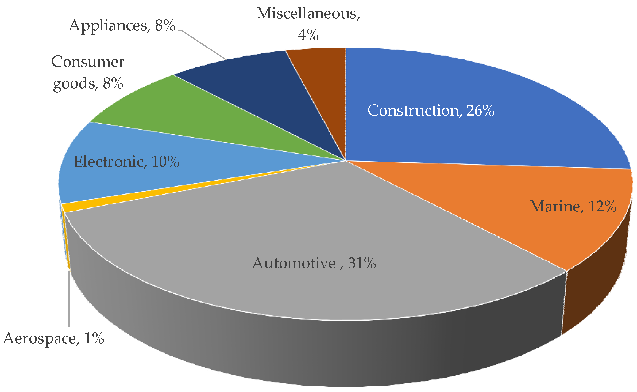
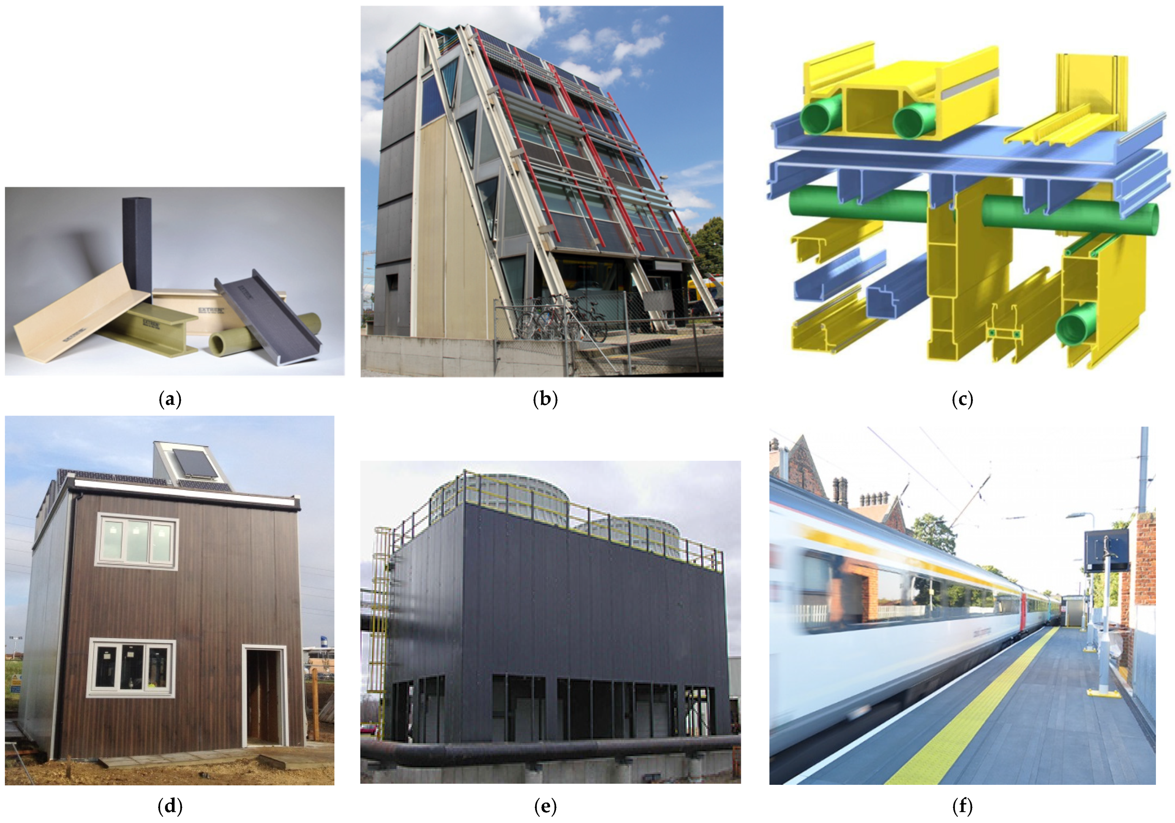
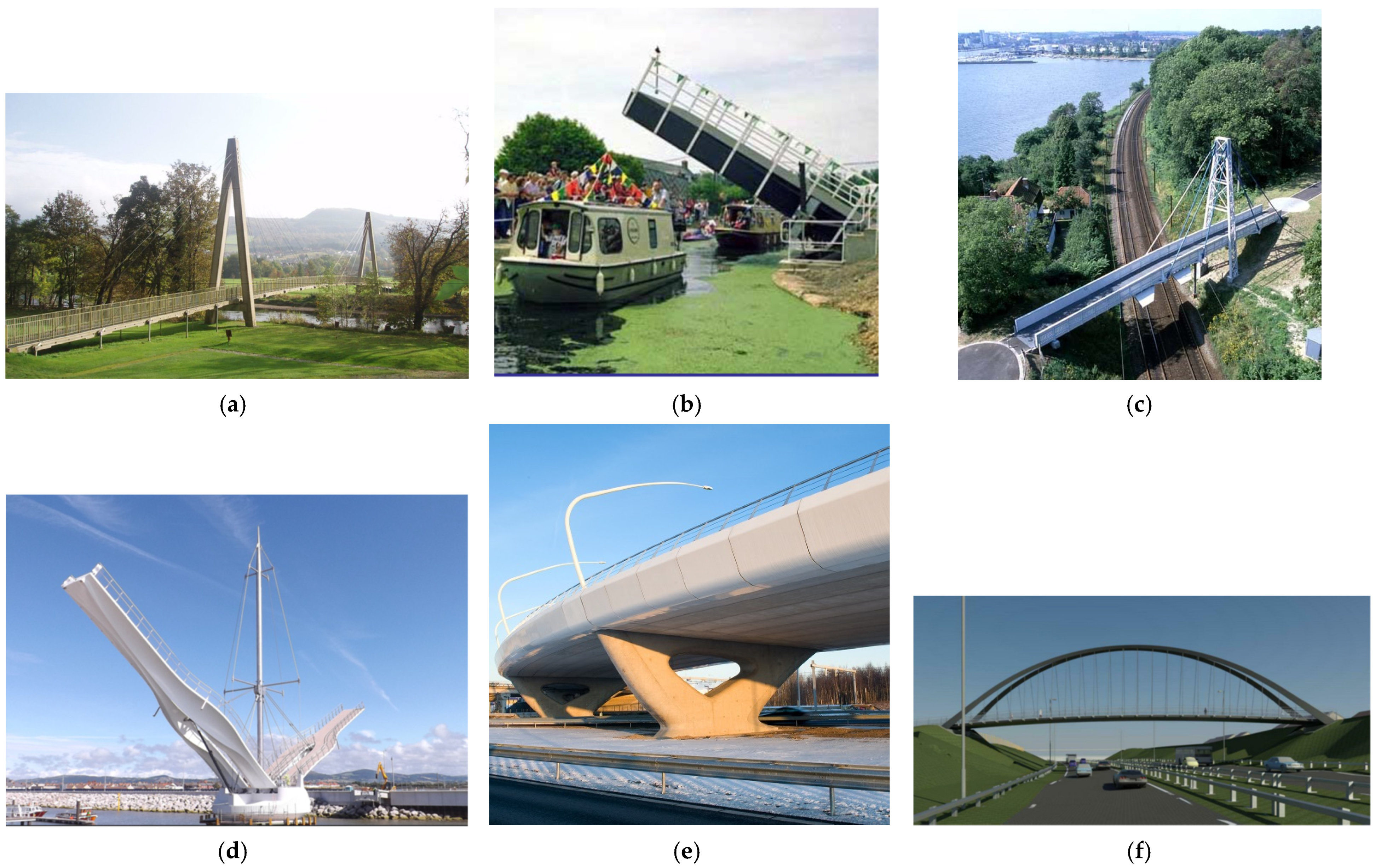
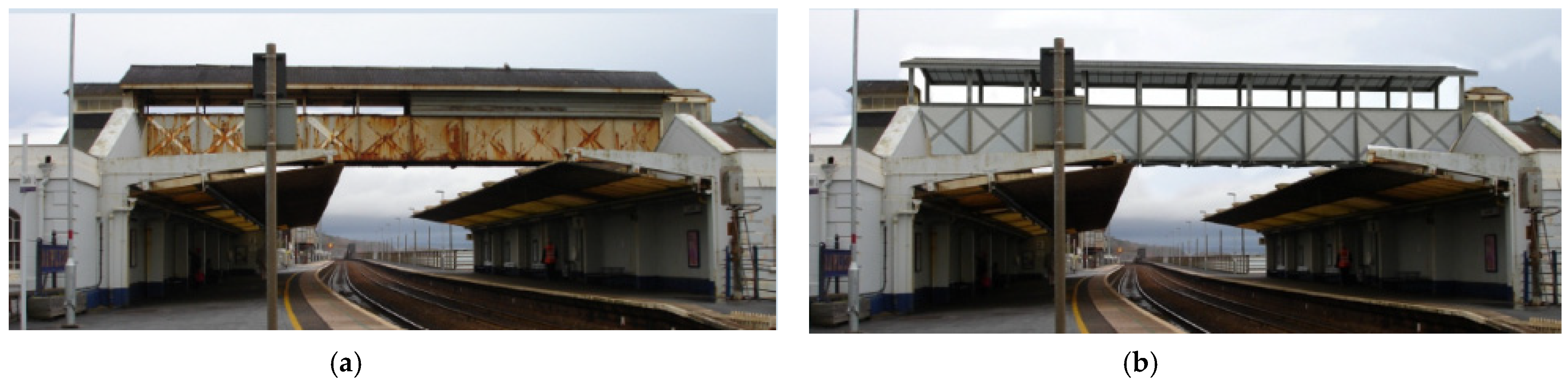
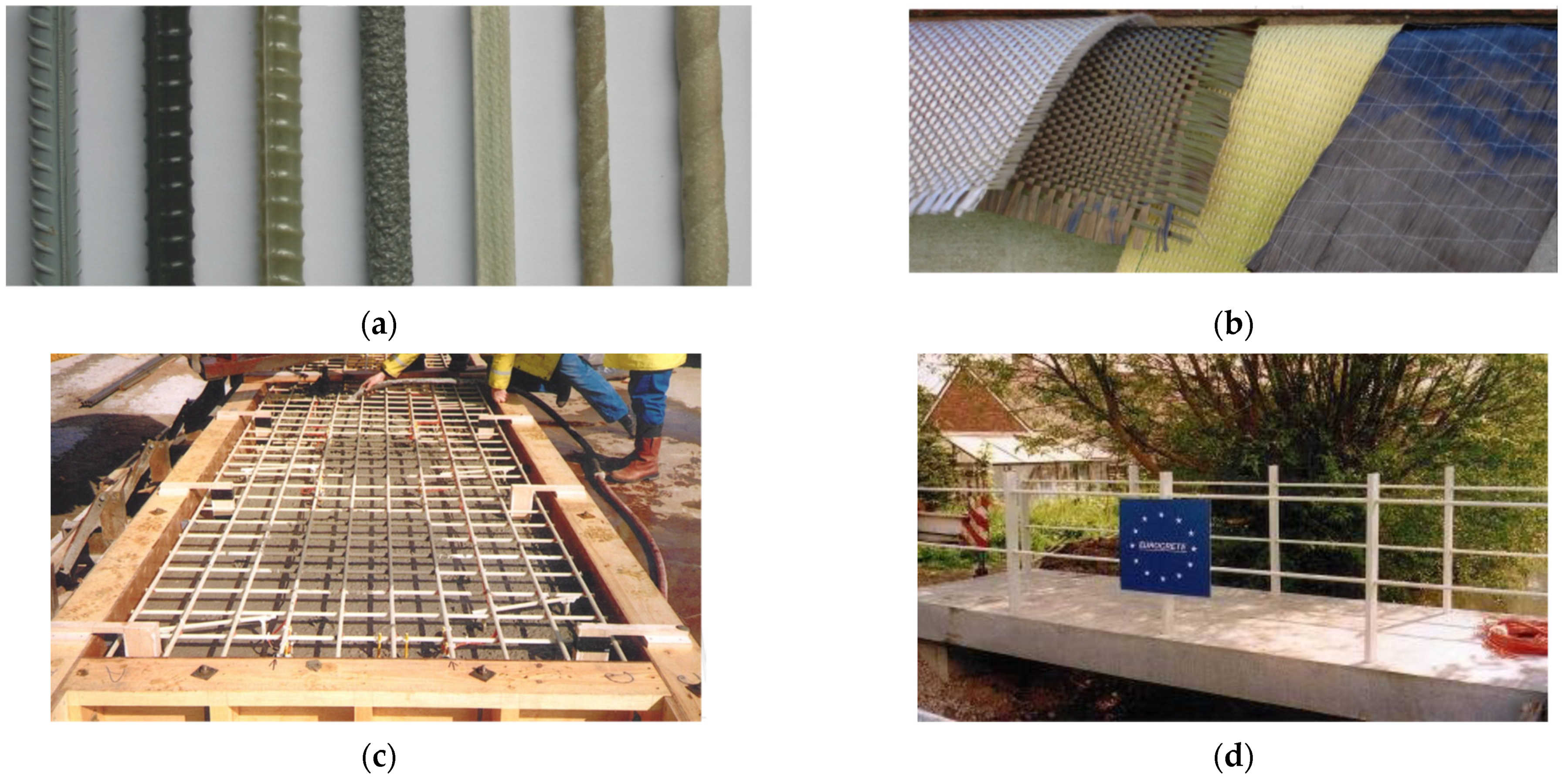
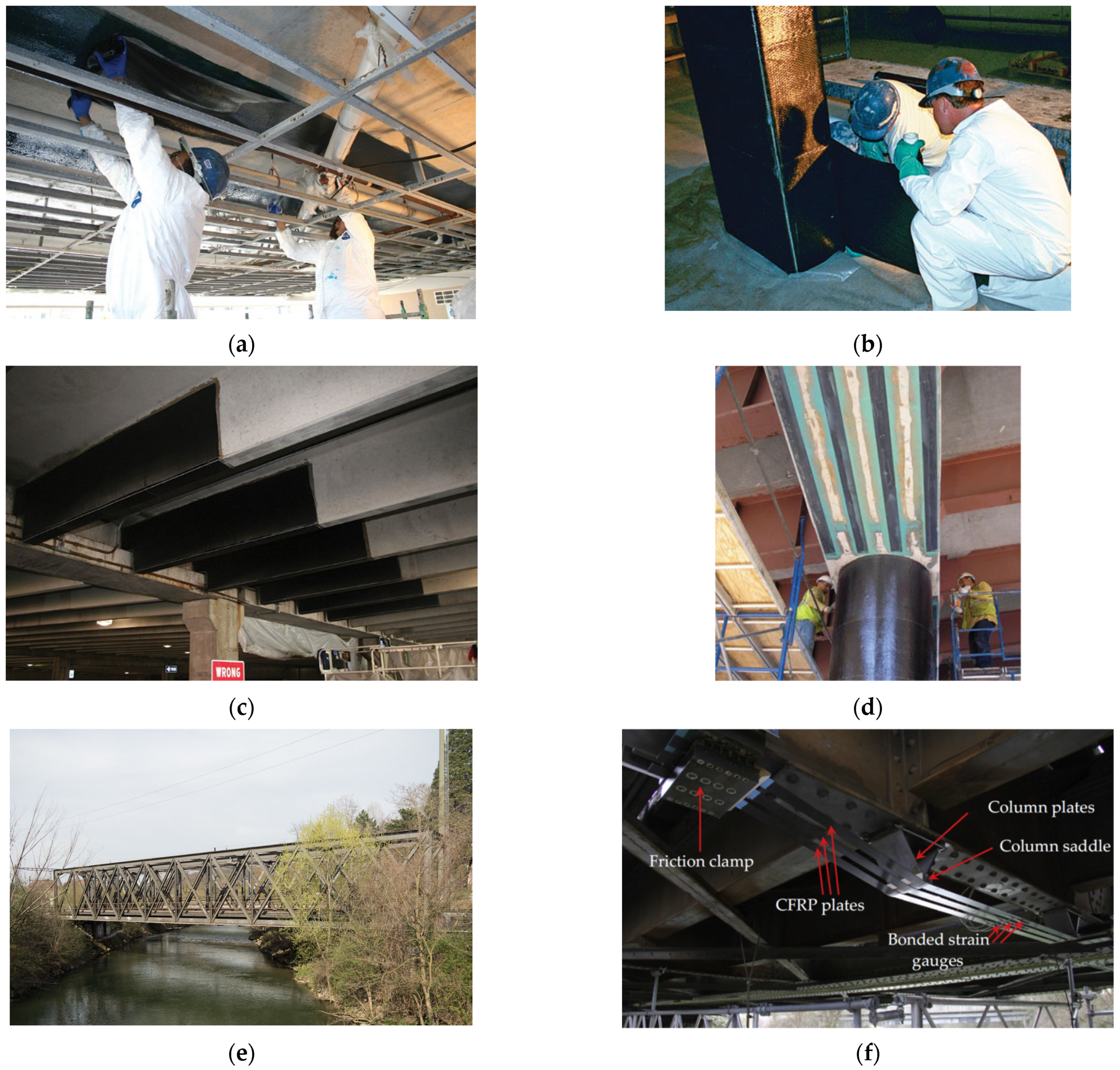
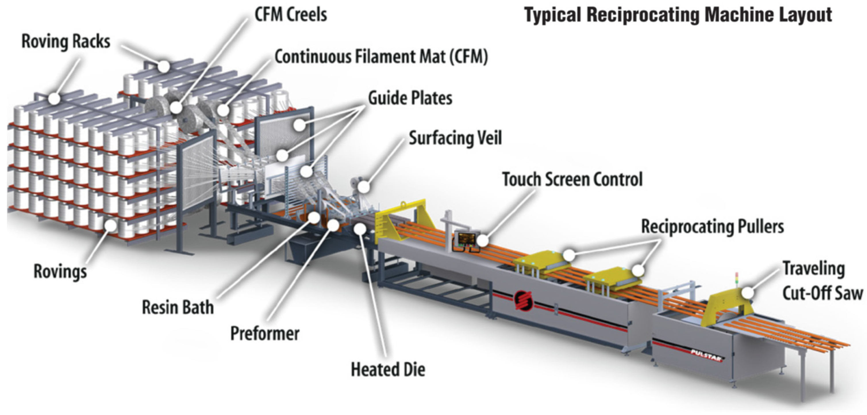
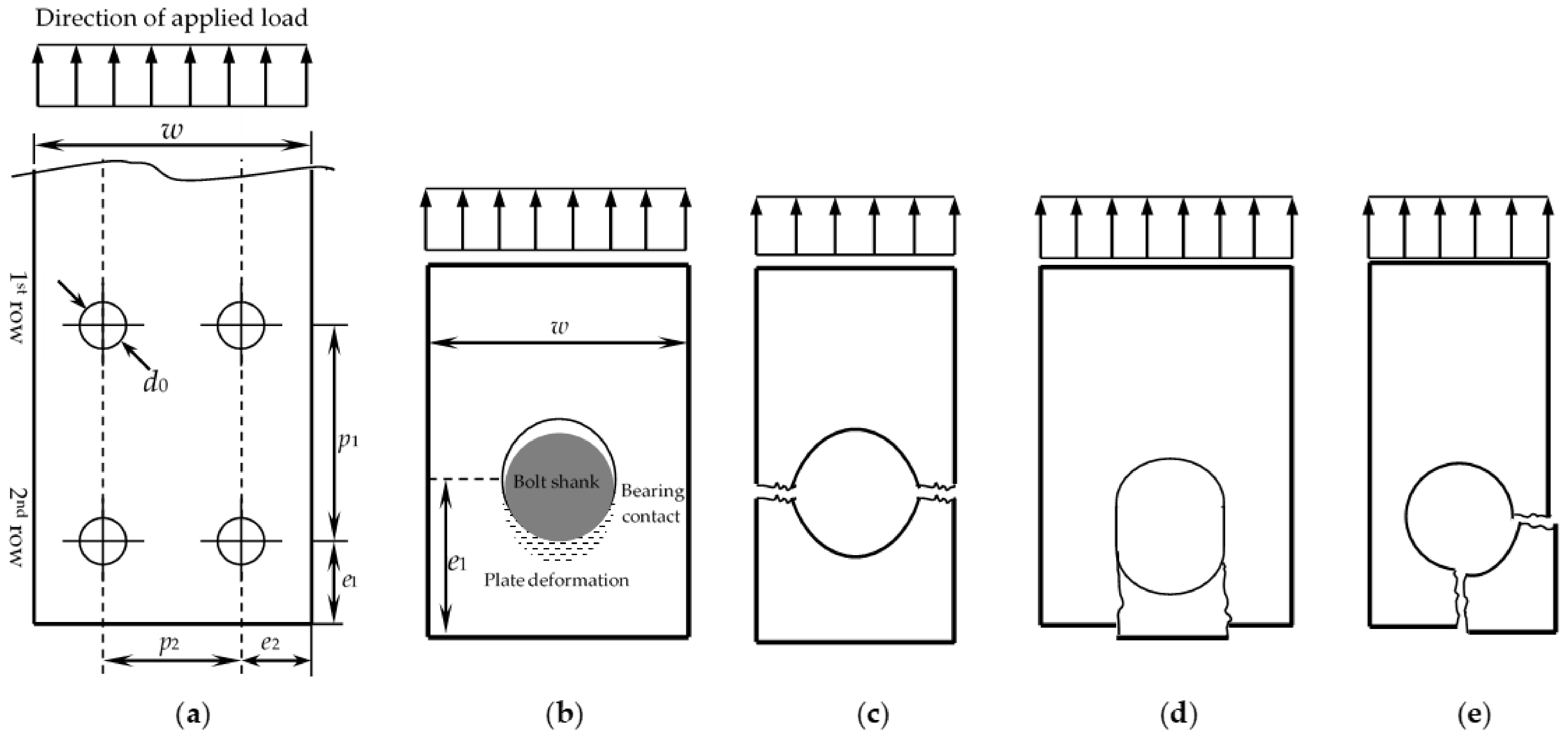
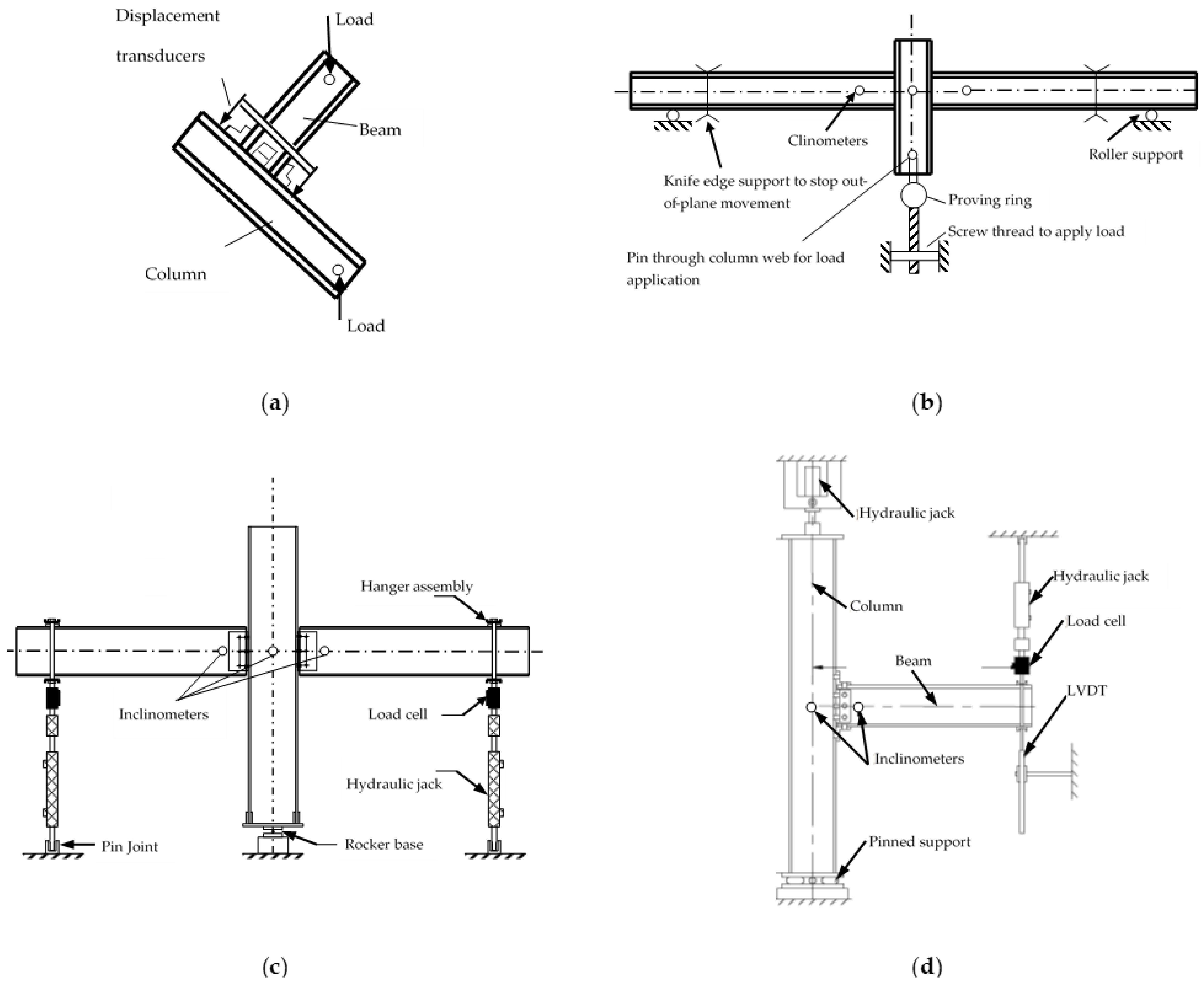
Figure 2.
Applications of FRP in buildings and other structures: (a) Glass fibre reinforced polymer structural shapes [12]; (b) Five-storey Eyecatcher FRP demountable building Switzerland [31]; (c) Startlink test house modular pultruded FRP concept profiles [32]; (d) Startlink—Fully composite test house [33]; (e) Pultruded FRP cooling tower [12]; (f) Duracomposites railway platforms [34].

Figure 3.
Applications of FRP in bridges: (a) Aberfeldy Scotland footbridge [35]; (b) Bonds Mill lifting bridge [36]; (c) Kolding Denmark FRP pedestrian bridge, 1997 [9,37]; (d) The Pont y Ddraig, the Dragon bascule bridge in Wales, 2013 [38]; (e) Fly-over Waarderpolder bridge in Netherland with FRP edge elements [39]; (f) Emersons Green Cycle Footbridge, Bristol UK [40].

Figure 4.
Dawlish pedestrian bridge Exeter UK: (a) Old rusty steel bridge, 1937 [47]; (b) New FRP bridge, 2011 [47].

Figure 6.
FRP in strengthening applications: (a) Flexural strengthening of slab [68]; (b) Wrapping FRP fabrics around concrete columns [68]; (c) CFRP strengthening of beams [68]; (d) FRP plates bonded to beams [66]; (e) Münchenstein Railway Bridge (120 years old) Switzerland [69]; (f) CFRP strengthening of Münchenstein bridge with sensors to monitor long-term prestress level [69].

Figure 7.
Schematic diagram of pultrusion process (Courtesy of Strongwell [12]).
Figure 7.
Schematic diagram of pultrusion process (Courtesy of Strongwell [12]).

Figure 8.
Geometry and failure modes of FRP plate-to-plate connections [23]; (a) Connection geometry; (b) Bearing failure; (c) Net-tension failure; (d) Shear-out failure; (e) Cleavage failure.
Figure 8.
Geometry and failure modes of FRP plate-to-plate connections [23]; (a) Connection geometry; (b) Bearing failure; (c) Net-tension failure; (d) Shear-out failure; (e) Cleavage failure.

Figure 9.
Test arrangement for beam-to-column joints; (a) Direct Compression [25]; (b) Simply supported beam [25]; (c) Double cantilever beam [27]; (d) Single cantilever beam [7,8,128].

Table 2.
Mechanical properties of pultruded FRP wide-flanged profiles (Glass reinforced Vinylester shapes 6–13 mm thick) [2,6,7].
| Estimated Fibre Volume | 25–40% | ||
| Fibre architecture | Roving and mat | ||
| Strength (MPa) | Tensile | Longitudinal | 207–317 |
| Transverse | 48–83 | ||
| Compressive | Longitudinal | 207–359 | |
| Transverse | 110–138 | ||
| Shear | In-plane | 31–48 | |
| Out-of-plane | 27–31 | ||
| Flexural | Longitudinal | 207–338 | |
| Transverse | 69–131 | ||
| Bearing | Longitudinal | 207–269 | |
| Transverse | 179–234 | ||
| Modulus (GPa) | Tensile | Longitudinal | 18–28 |
| Transverse | 6–10 | ||
| Compressive | Longitudinal | 18–26 | |
| Transverse | 7–13 | ||
| Shear | In-plane | 3.0–3.4 | |
| Flexural | Longitudinal | 11–14 | |
| Transverse | 6–12 | ||
| Poisson’s ratio | Longitudinal | 0.33–0.35 | |
Table 3.
Comparion of tensile properties of steel and FRP rebars (with volume fraction of fibre from 50 to 75%) [48].
Table 3.
Comparion of tensile properties of steel and FRP rebars (with volume fraction of fibre from 50 to 75%) [48].
| Property | Material | |||
|---|---|---|---|---|
| Steel | GFRP | CFRP | AFRP | |
| Longitudinal modulus (GPa) | 200 | 35 to 60 | 100 to 580 | 40 to 125 |
| Longitudinal tensile strength (MPa) | 450 to 700 | 450 to 1600 | 600 to 3500 | 1000 to 2500 |
| Ultimate tensile strain (%) | 5 to 20 | 1.2 to 3.7 | 0.5 to 1.7 | 1.9 to 4.4 |
| Property | GFRP | CFRP | AFRP |
|---|---|---|---|
| E-Glass/Epoxy | Carbon/Epoxy | Kevlar 49/Epoxy | |
| Fibre volume fraction | 0.55 | 0.65 | 0.60 |
| Density (kg/m3) | 2100 | 1600 | 1380 |
| Longitudinal modulus (GPa) | 39 | 177 | 87 |
| Transverse modulus (GPa) | 8.6 | 10.8 | 5.5 |
| In-plane shear modulus (GPa) | 3.8 | 7.6 | 2.2 |
| Major Poisson’s ratio | 0.28 | 0.27 | 0.34 |
| Minor Poisson’s ratio | 0.06 | 0.02 | 0.02 |
| Longitudinal tensile strength (MPa) | 1080 | 2860 | 1280 |
| Transverse tensile strength (MPa) | 39 | 49 | 30 |
| In-plane shear strength (MPa) | 89 | 83 | 49 |
| Ultimate longitudinal tensile strain (%) | 2.8 | 1.6 | 1.5 |
| Ultimate transverse tensile strain (%) | 0.5 | 0.5 | 0.5 |
| Longitudinal compressive strength (MPa) | 620 | 1875 | 335 |
| Transverse compressive strength (MPa) | 128 | 246 | 158 |
Table 6.
Main findings for FRP frame joints subjected to monotonic loading.
| Researcher | Set Up | Sizes | Joint Configuration | Main Findings |
|---|---|---|---|---|
| Bank [129,130,131] | Direct Compression |
|
|
|
| Mottram [24,132,133,134] | Double cantilever |
|
|
|
| Mosallam [135,136] | Direct compression |
|
|
|
| Qureshi [27,28,29,137] | Double cantilever |
|
|
|
| Turvey [138,139,140,141,142] | Double cantilever |
|
|
|
| Qureshi [80] | Tension pull test |
|
|
|
| Smith [143,144,145] | Direct Compression |
|
|
|
| Zafari [33,146] | Single cantilever |
|
|
|
| Russo [147,148,149] | Simply supported beam |
|
|
|
| Zhang [150] | Single cantilever |
|
|
|
| Martins [151,152,153] | Single cantilever and full frame |
|
|
|
| Ascione [18,154] | Single cantilever |
|
|
|
| Mosallam [155] | Web-flange junction tests |
|
|
|
Table 7.
Main findings for FRP frame joints subjected to cyclic loading.
| Researcher | Set Up | Sizes | Joint Configuration | Main Findings |
|---|---|---|---|---|
| Bruneau and Walker [156] | Simply support beam |
|
|
|
| Mosallam [135] | Direct compression |
|
|
|
| Smith [144,145], Singamsethi [157], Carrion [158] | Direct compression |
|
|
|
| Zhang, Qiu [150,159,160] | Single cantilever or beam splice connection |
|
|
|
| Martins [161,162] | Single cantilever |
|
|
|
| Razaqpur [163] | Single cantilever |
|
|
|
| Qureshi [8,128] | Single cantilever |
|
|
|
Table 8.
Advantages and limitations of different test set ups and joint configurations.
| Test Set Up | Joint Configuration | Advantages and Findings | Limitations |
|---|---|---|---|
| Direct compression | - |
|
|
| Simply supported beam | - |
|
|
| Double cantilever beam | - |
|
|
| Single cantilever beam | - |
|
|
| Full scale frame | - |
|
|
| - | Cleated joints |
|
|
| - | Sleeve/cuff joints |
|
|
Publisher’s Note: MDPI stays neutral with regard to jurisdictional claims in published maps and institutional affiliations. |
© 2022 by the author. Licensee MDPI, Basel, Switzerland. This article is an open access article distributed under the terms and conditions of the Creative Commons Attribution (CC BY) license (https://creativecommons.org/licenses/by/4.0/).
Share and Cite
MDPI and ACS Style
Qureshi, J. A Review of Fibre Reinforced Polymer Structures. Fibers 2022, 10, 27. https://doi.org/10.3390/fib10030027
AMA Style
Qureshi J. A Review of Fibre Reinforced Polymer Structures. Fibers. 2022; 10(3):27. https://doi.org/10.3390/fib10030027
Chicago/Turabian StyleQureshi, Jawed. 2022. "A Review of Fibre Reinforced Polymer Structures" Fibers 10, no. 3: 27. https://doi.org/10.3390/fib10030027
Note that from the first issue of 2016, this journal uses article numbers instead of page numbers. See further details here.