
The Impact of Baffle Geometry in the PCM Heat Storage Unit on the Charging Process with High and Low Water Streams

Department of Energy Conversion Engineering, Wroclaw University of Science and Technology, 50-370 Wrocław, Poland
*
Authors to whom correspondence should be addressed.
Energies 2022, 15(24), 9349; https://doi.org/10.3390/en15249349
Submission received: 20 October 2022
/
Revised: 28 November 2022
/
Accepted: 3 December 2022
/
Published: 9 December 2022
(This article belongs to the Section D: Energy Storage and Application)
Abstract
:This paper presents the effect of baffle geometry on the charging process of a low-temperature heat storage unit. Four different geometry variants were considered for this purpose. Each of them was simulated and the results were compared. The following parameters were selected as comparison criteria: the charging time of the heat storage unit, the change in the liquid and solid fractions of the phase change material, and the change in its temperature over time. The analysis showed that, independent from the heat transfer fluid velocity, the use of baffles did not significantly affect the charging time. Furthermore, the application of baffles of all studied types did not bring an essential decrease in charging time. It was found that the optimal solution was to use the simplest construction. Tuning of the HTF flow by the use of baffles is applicable to shell and tube heat exchangers; however, it adds no significant effects in the case of heat storage units of the proposed design. The abovementioned effect has been explained by the heat flux analysis, which shows that the heat transfer in the PCM is radically less intense, when comparing to the working fluid. Therefore, it is expected that enhancing the heat transfer between HTF and PCM material is possible by modifying the PCM–side design.
1. Introduction
In the last few decades, the global energy demand has been grown rapidly [1]. It has been reported [2] that in the European Union (EU), approx. 40% of energy is currently used for heating and lighting purposes. Moreover, until 2015, the largest share of energy consumed in the EU came from fossil fuels (72.6% of gross energy consumption) [3]. Since the use of fossil fuels contributes to the increase in greenhouse gas emissions and their gathering results in an increase in the costs [4,5], it is expected that renewable energy sources will provide an alternative [6].
Currently, wind and solar energy are the most widely used renewable energy sources. As much as 57% of all investments in renewable energy in Europe and the United States have been made in solar energy [7]. However, renewable energy sources (RES) are characterized by variable operation [8,9]. In turn, this brings issues related to the transmission capacity of power lines [10]. In order to take full advantage of the RES potential, energy storage solutions are being intensively developed [11]. The storage technologies currently available depend on the form of energy. Energy is most commonly stored in the form of electricity [12] or heat.
Available studies show that in recent years, more than 50% of the energy consumed in Europe has been lost in the form of heat [13]. Thus, heat recovery and storage technologies have an increasing potential [14,15] which leads to their wider use [12,16]. The total potential of waste heat recovery in Europe is estimated to be around 300 TWh/year [17]. Waste heat storage solutions address the problem of mismatch between availability and demand [18]. Statistical data show that industrial activity and power generation are not only the most energy-intensive sectors, but also generate large amounts of waste heat [19]. The possibility of recovery and reuse of this heat increases the development of more efficient energy sources and reduces greenhouse gas emissions [18].
Heat storage solutions may be classified by the operating temperature and, as a result, by the heat storage material used. The main classification is as follows:
- high temperature heat storage solutions–play an essential role in the recovery of waste heat in industrial applications [18,23]. An example is the heat storage in an automotive paint facility [24]. The most commonly used materials are: mineral oil, molten salts, liquid metals or alloys, and zeolites [21].
Phase change materials (PCM) are frequently proposed for application in heat storage units. The main advantage of PCMs is that they are able to store more heat per mass unit comparing to commonly used water. In addition, phase change materials are characterized by a large variety of properties, which allows the selection of an optimal material depending on the parameters of the heat source.
The bases for efficient operation of a heat storage unit are the efficient charging and discharging process, as well as the possibility of using the entire heat capacity of the storage material. Therefore, the heat transfer between the heat transfer fluid that supplies/receives heat and the storage material is essential. It is affected by such factors as temperature difference between the heating medium and the storage material, the elements of the heat exchange system, and the heat storage material used.
The main drawback of most phase change materials is relatively low thermal conductivity [25,26], which results in high charging and discharging time. To increase the efficiency of these processes, heat transfer in the material needs to be improved. For this purpose, i.e., the following modifications of elements of the heat exchange system may be used:
- ○
- increasing the heat transfer surface area by:
- ○
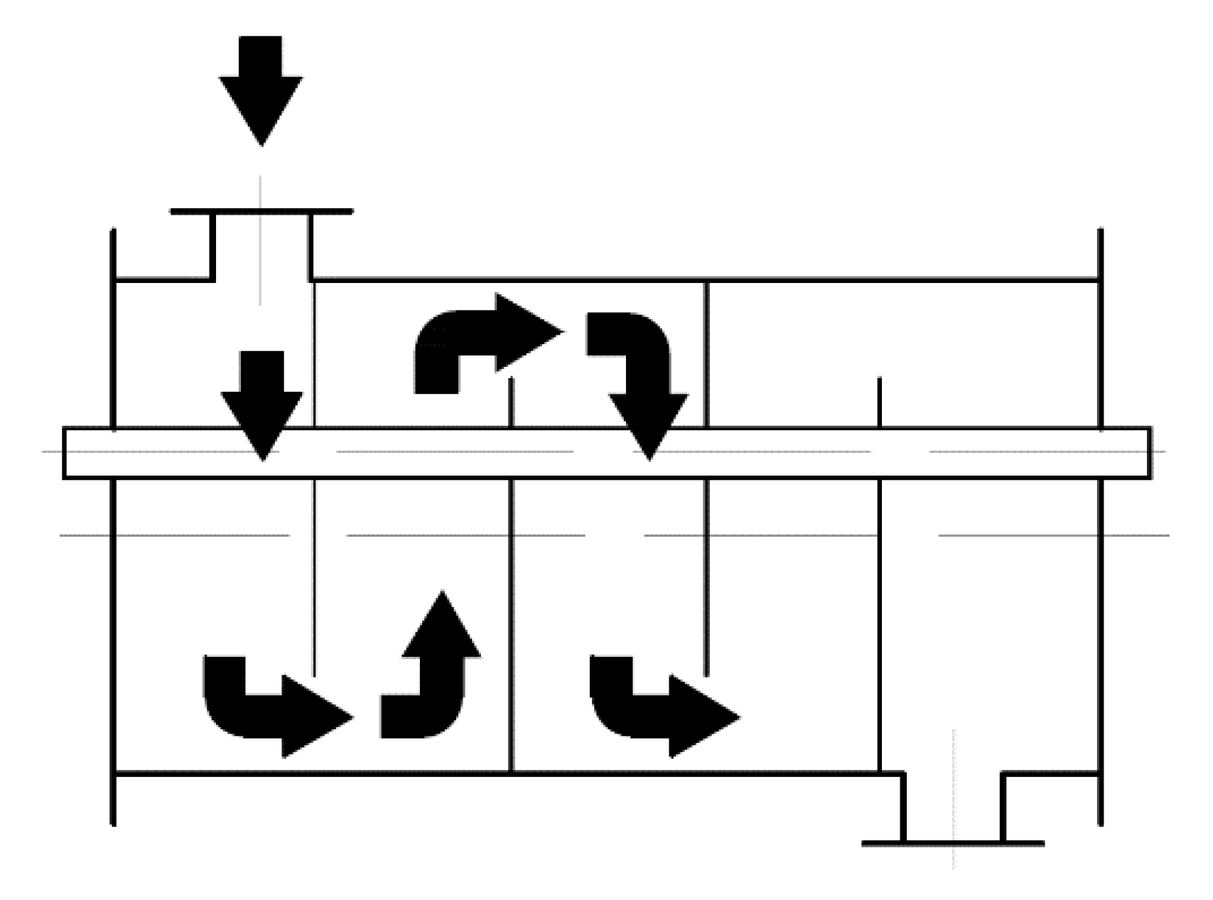
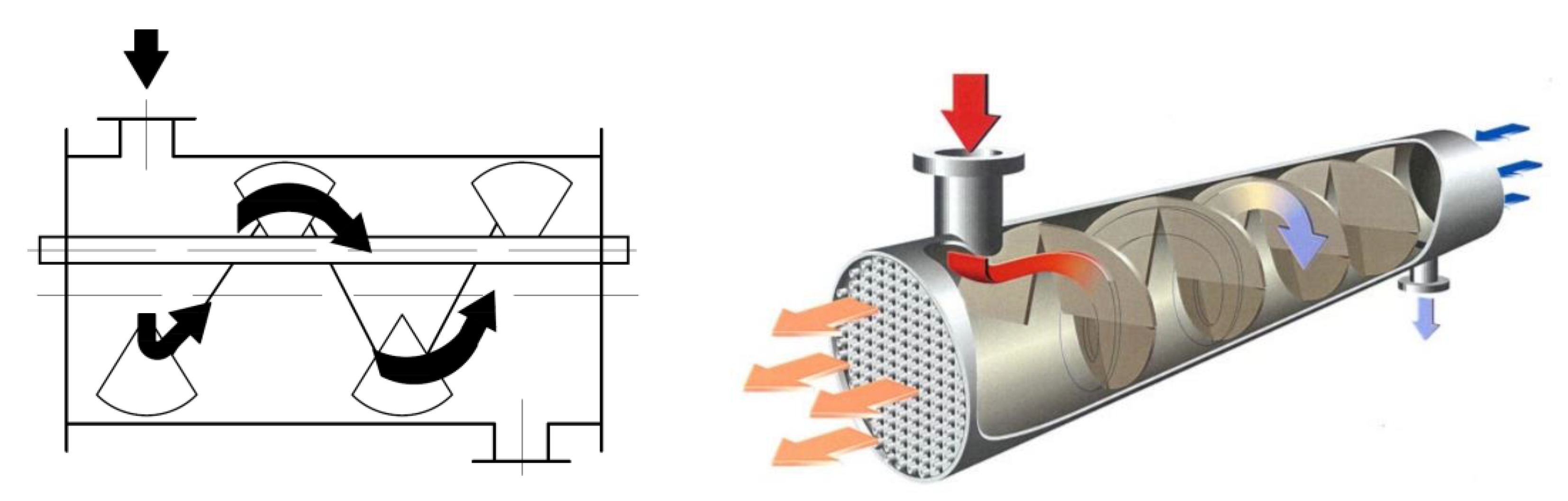
- changing the flow character of the heat transfer fluid (HTF) by using turbulizers:
The modifications presented above may be optimized to achieve a more efficient heat transfer. In the case of shell and tube design, the typical construction upgrades include the application of several types of baffles, such as a longitudinal baffle and a helical baffle, to increase the heat transfer rate [29]. Another modification is the change of the baffle geometry [31], including a different angle of the baffle in relation to the axis of the tube. It was reported [32] that the smaller the angles of inclination of the baffles, the higher the heat transfer coefficient. The abovementioned enhancements in shell and tube design are common for heat exchanges. Such geometry may be adopted for heat storage units, theoretically without significant changes in the design. However, it has to be emphasized, that in the case of a heat exchanger, heat transfer is performed from hot flowing medium to cold flowing medium. In contrast, in a heat storage unit, heat is being transferred from hot flowing medium (working fluid) to the PCM, which is stationary in both solid and liquid phases [33].
Therefore, the purpose of the research described in this paper is to study the effect of modifying the elements of geometry of the shell and tube heat storage unit on the heat transfer efficiency. It is common knowledge that tuning the HTF flow pattern may enhance the heat transfer in typical shell and tube heat exchangers with two working fluids. In contrast to a heat exchanger, the heat storage unit based on shell and tube design has a working fluid in the shell part and a static PCM filling inside the tubes. The goal was to investigate if the application of baffles, which modify the working fluid flow, affects the heat transfer between the working fluid and the PCM material. The analyzed modifications consist of the use of turbulizers in three different shapes that alter the flow of the working fluid. The evaluation of the impact of the modifications was performed on the basis of numerical simulations. CFD simulations of the charging process of the heat storage unit have been performed. The impact of the temperature change on the heat storage unit, charging time, as well as heat flux have also been analyzed.
2. Research Methodology
2.1. Physical Model
For the purposes of numerical simulations, the geometry of the heat exchanger installed in the laboratory has been assumed. The laboratory heat storage unit at the Wroclaw University of Science and Technology is used for testing materials for heat storage. The exchanger consists of a copper pipe with a length of 2.7 m and a diameter of 480 mm. The inner part of the exchanger is filled with PCM–RT64HC [34] paraffin. The properties of paraffin are shown in Table 1. The heating medium, i.e., water (80 °C when charging), flows through the outer shell.
2.2. Numerical Models
The selection of baffles/helix configuration was based on the literature, where it was reported that in the case of half–circular baffles, “the thermal efficiency factor is 3.55 times more than for a case without the baffle” [35,36]. In the case of helical baffles, according to [35,36] “Overall heat transfer performance is increased by 161.3%”. The aforementioned observations were presented for shell and tube heat exchangers, where HTF flow is in both the shell and tube parts. In our study, HTF flow is only in the shell part, while the tubes are filled with static PCM material. The aim of this study was to verify whether the baffle impact on the heat transfer enhancement observed in the case of regular shell and tube heat exchanger is also valid for shell and tube PCM heat storage unit.
The selection of parameters, e.g., baffle spacing, helix angle, etc., was based on both literature reports as well as our laboratory stand design experience. According to [37], a shell and tube heat exchanger, which had equal baffle spacing configuration, had the smallest pressure drop and highest thermal performance among all the schemes. The other studied baffle configurations in [37] included nonuniform baffle spacing in several variants.
The design of the helical baffle model is the most innovative in our study, as the role of the helix is tuning the flow pattern without simultaneously generating a large pressure drop. This is particularly important in the studied case, as the HTF stream is large. Based on literature sources [38], helical baffles are expected to generate a smaller pressure drop compared to segmental baffles. The design in our study is a step forward, as the helical baffle is reduced to the inner shell area and does not separate the inter-tubular zone. The goal of the presented design solution is to tune the HTF flow pattern.
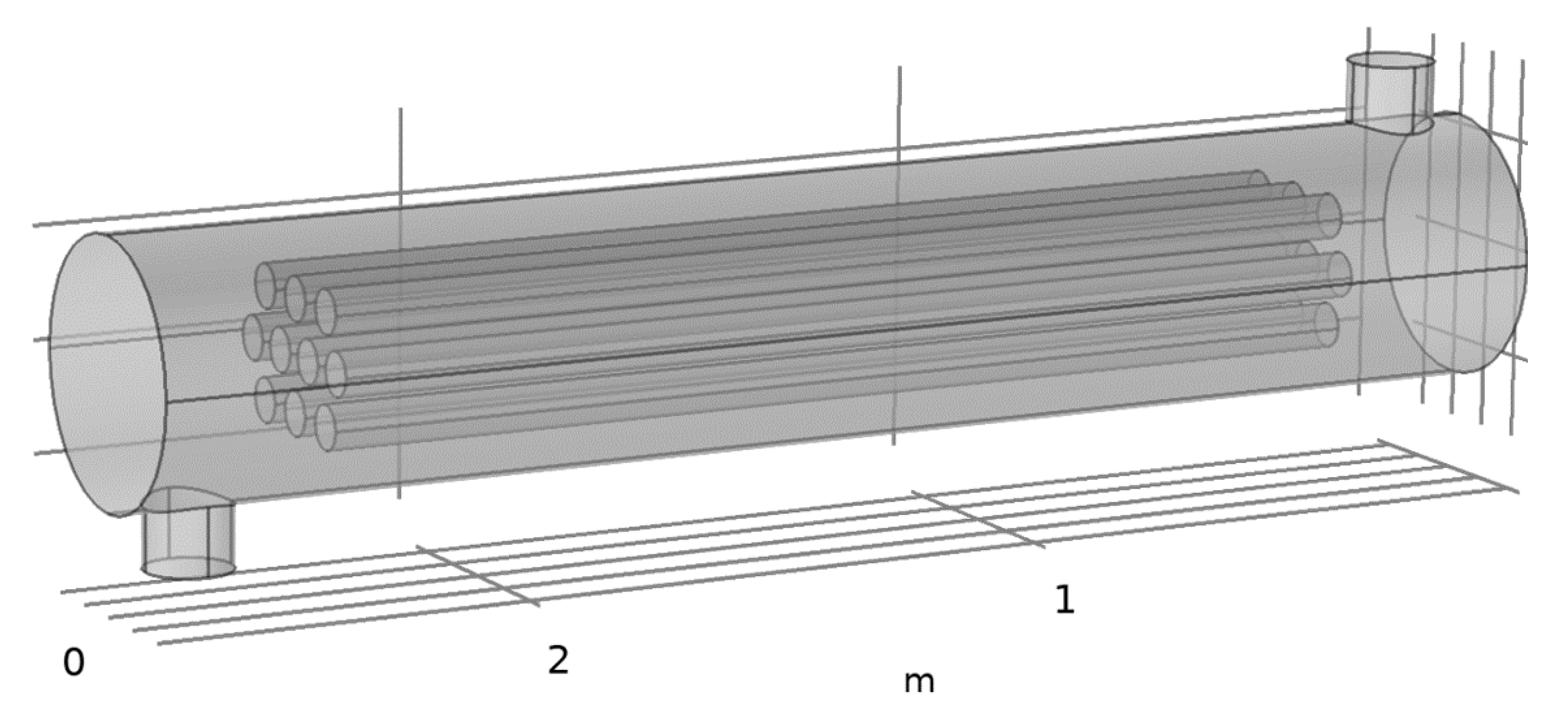
2.2.1. Model 1
Figure 3 shows the base model of the heat exchanger, which is a modification of the actual geometry described in the previous section. It consists of 10 tubes with an inner diameter of 80 mm and length of 2 m. This arrangement increases the heat transfer surface area between the fluid flowing in the shell and the tubes containing the phase change material.
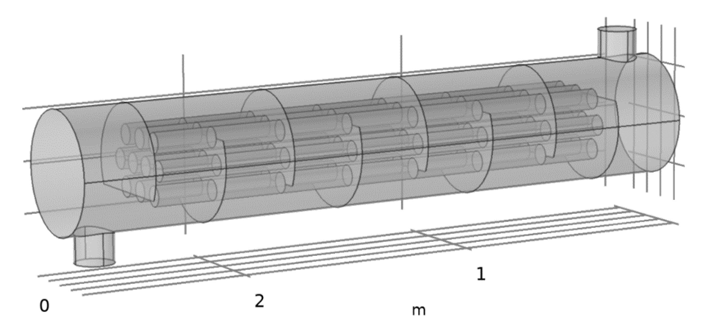
2.2.2. Model 2
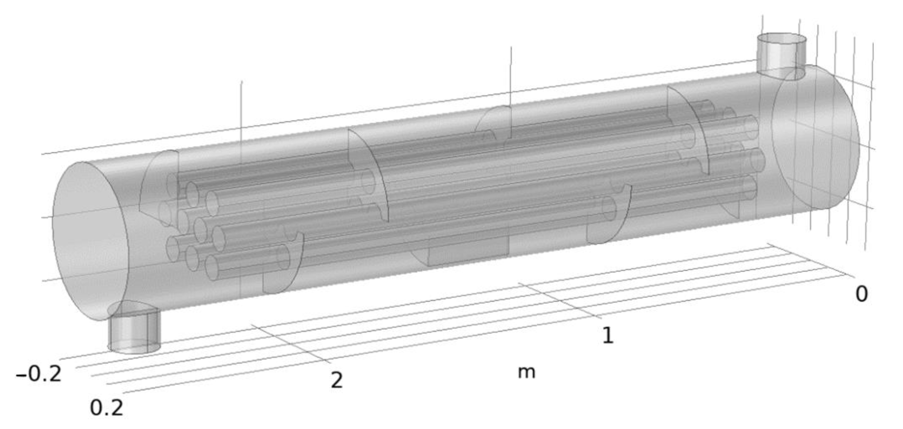
Figure 4 presents Model 2, which is a modification of Model 1. Perpendicular to the axis of the pipes, there are partitions, which take up about 2/3 of the diameter of the heat storage unit.
2.2.3. Model 3
Figure 5 shows Model 3. An additional modification are the partitions, which take up 1/4 of the transverse surface of the thermal energy storage (TES).
2.2.4. Model 4
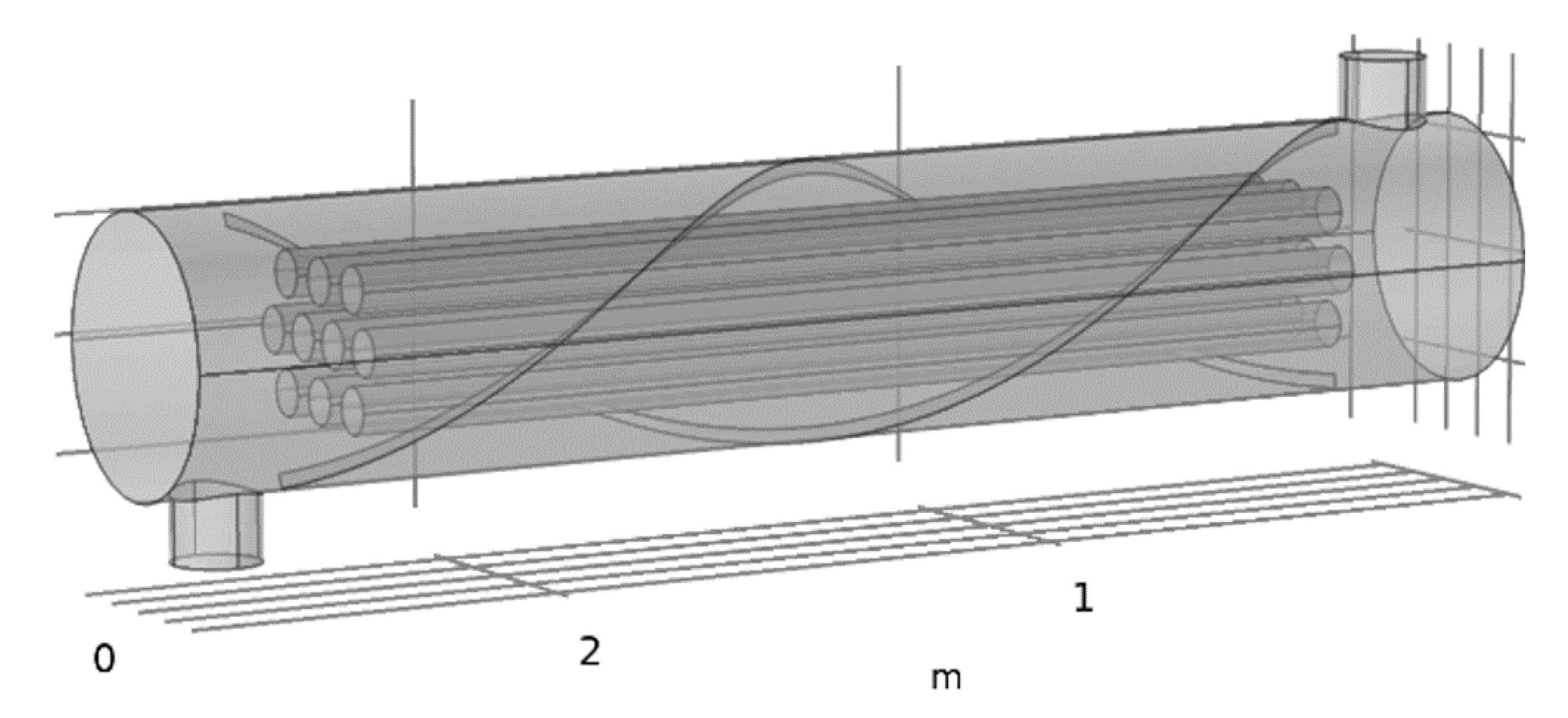
Figure 6 shows Model 4. The modification introduced here is a helical baffle. The purpose of using the helical baffle is to induce additional fluid flow in the shell.
2.3. Numerical Mesh
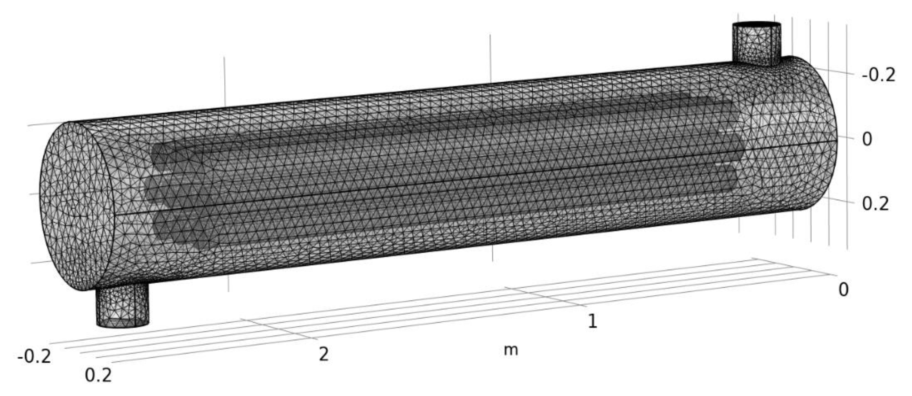
A numerical mesh for each of the models was generated in Comsol Multiphysics software. The mesh geometry was tuned to increase the accuracy of the calculations at the points of contact between the wall and the phase change material, as well as between the wall and the heat transport medium, i.e., water. Its detailed parameters are presented in Table 2. Between the tube and water, as well as between the tube and the phase change material, contact regions that link the thermal conditions of both walls were included. A view of the mesh is shown in Figure 7.
2.4. Mathematical Model of Heat Transfer in the Heat Storage Unit
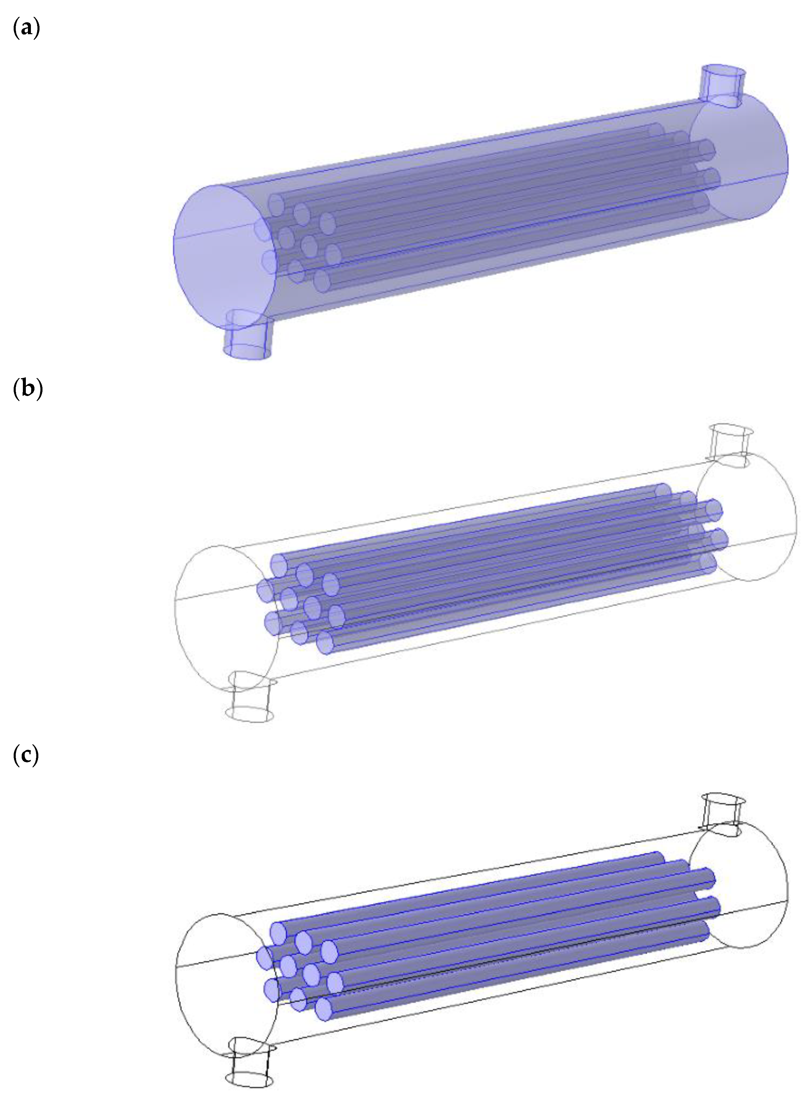
The model was divided into three domains. The first domain is the zone of the heat transfer medium, i.e., water (Figure 8a), where the process of heat transfer from water to the tube wall has been taken into account. The second is the zone that includes the tube wall (Figure 8b). The process of transferring heat from water to the tube wall has been taken into account. The third is the area of the phase change material (Figure 8c). The calculations of third zone (phase change material) take into account the fact that PCM properties are changing depending on the state of matter and temperature.
The heat capacity of the material at a given temperature can be calculated using Equations (1) and (2) [33,39]:
where:
- HPCM—enthalpy of the material at a given temperature, J/kg
- hPCM—enthalpy, J/kg
- ΔHPCM—heat capacity (difference in enthalpies), J/kg
- href—standard enthalpy, J/kg
- Tref—standard temperature, °C
- —specific heat of the material at constant pressure, J/(kg·°C)
The amount of heat stored in a given amount of PCM can also be expressed by Equation (3) [33,39]:
where:
- LPCM—latent heat of the material in liquid state
- —proportion of the liquid phase
The proportion of the liquid phase is described by relation (4) [39]:
where:
- —melting point, °C
- Ts—solidification point, °C
However, using only these relations for the liquid phase will result in insufficient convergence of the energy equation [39]. For transformations such as solidification/melting, the energy equation takes the form expressed by Equations (5)–(8) [39]:
where:
- —density, kg/m3
- —velocity, m/s
- —fraction of the solid phase
- —specific heat of the solid material at constant pressure, J/(kg·°C)
- —specific heat of the liquid material at constant pressure, J/(kg·°C)
- —phase change enthalpy, J/kg
- —thermal conductivity of the solid material (W/(m·°C))
- —thermal conductivity of the liquid material (W/(m·°C))
In order to include the effect of natural convection in the PCM, the fluid density is defined by the Boussinesq equation [39], which assumes that density is a constant value in all solved equations. The exception is the lift period, when the change in density drives the flow in natural convection and is captured by taking into account the Boussinesq approximation:
where:
- —initial fluid density, kg/m3,
- —set temperature, °C
- —coefficient of thermal expansion, 1/°C.
The process of heat transfer in PCM material is represented by Equations (10) and (11) [33,39]:
where:
- —PCM density, kg/m3,
- —specific heat of the PCM at constant pressure, J/(kg·°C),
- —heat transfer vector
- —Thermal conductivity (W/(m·°C))
- —specific heat of the HTF at constant pressure, J/(kg·°C)
- —HTF density, kg/m3,
- —HTF velocity, m/s
- —heat source, W/m3
2.5. Solution of the Model
The model has been implemented and resolved in Comsol Multiphysics software. Due to the complexity of the phenomenon, i.e., the resulting turbulence in the flow and in areas close to the walls, the k-ε turbulence model was used.
2.6. Research Methodology
The simulations involved the charging process of the presented heat storage unit with a water stream. Two values of inlet water velocity were taken into account (Table 3) for each geometry variant (Figure 3, Figure 4, Figure 5 and Figure 6). The initial value of the temperature of all domains of the heat storage unit was equal to 20 °C and the simulations represented 180 min of continuous charging of the heat storage unit. The inlet water temperature was equal to 80 °C.
The results were analyzed for the temperature of the PCM material inside the tubes (front and central part of the selected tube) and temperature distribution in the PCM material, as well as the working fluid flow pattern in the shell zone. An important part of the study included the analysis of the heat flux in the working fluid and in the PCM material. This information is essential to explain which part of the heat storage unit may be modified to enhance the heat transfer. The effect of the application of baffles with different geometry on the temperature distribution in the PCM over time has been analyzed. In addition, these modifications were analyzed in terms of charging time of the TES. Charging time for all presented models was compared.
3. Results and Discussion
3.1. Analysis of the PCM Temperature during Charging
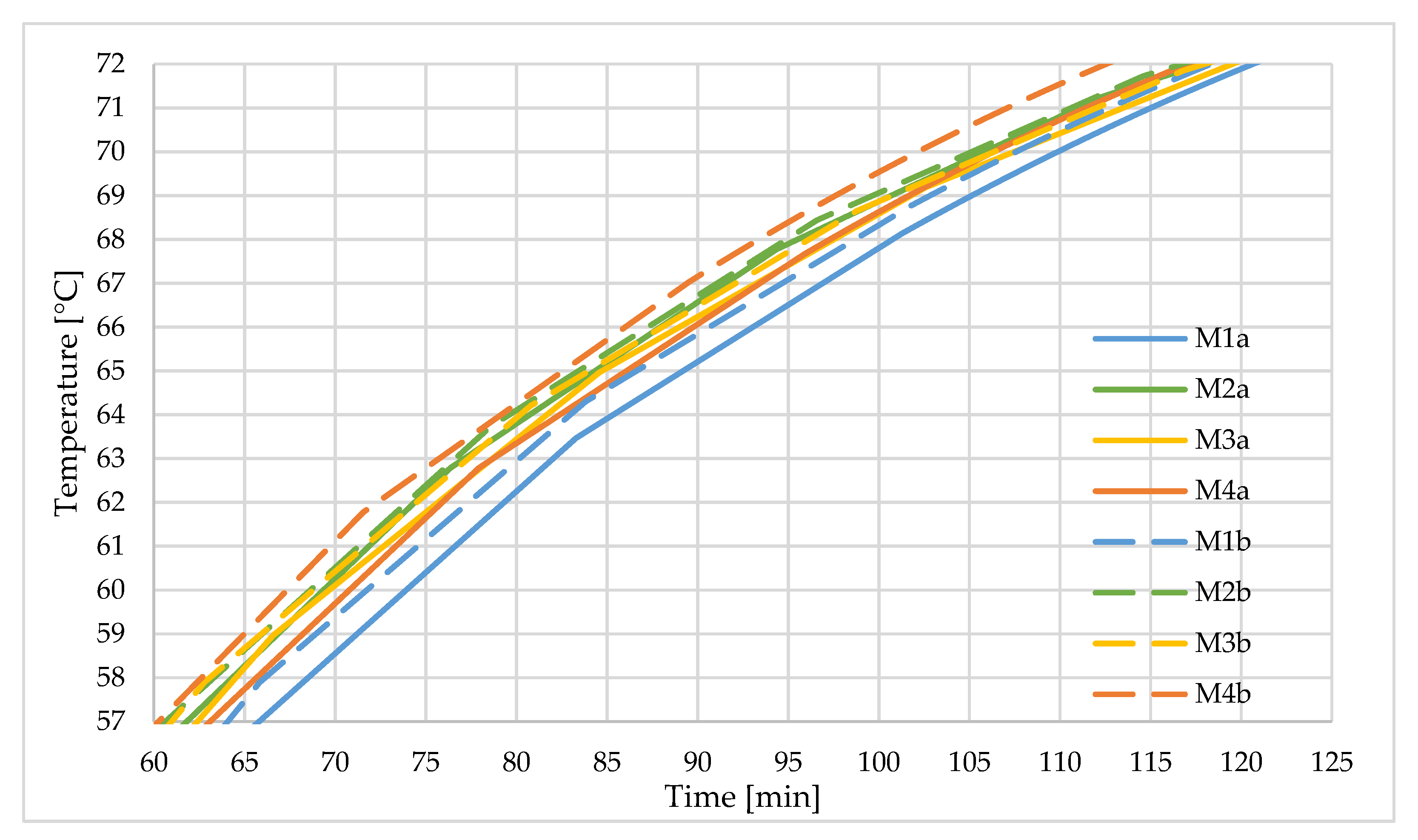
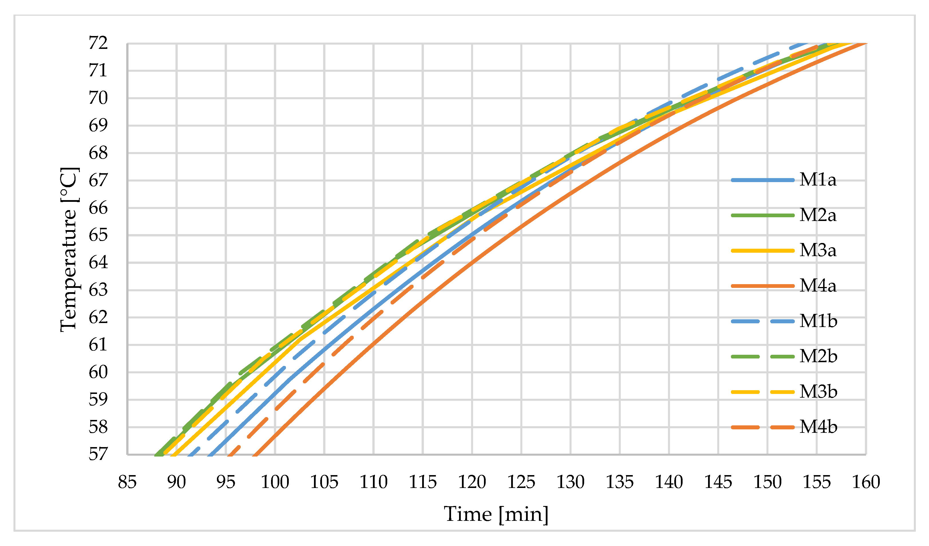
Figure 9 shows the temperature distribution at the front side of the tube in Models 1–4 for the working fluid velocity of 1 m/s (a), and 4 m/s (b). Figure 10 shows the temperature in the center of the tube over time for Models 1–4 with the working fluid velocity of 1 m/s (a), and 4 m/s (b). Both graphs show that there is no significant difference in the temperature distribution between the same geometry models with different flow rates of the working fluid.
The analysis of the temperature of the PCM material (Figure 9 and Figure 10) shows that the start of the PCM material melting (57 °C) in the central part of the tube is slightly different for each of the presented models. It varies from 88 min for M2 to 98 min for M4. The complete melting of the PCM (72 °C) is reached at a similar time (155–160 min). A similar observation is valid for the front part of the tube—the melting process starts at 60–65 min depending on the model, and end ca. 112–120 min. This means, that there are only subtle differences in charging time between the presented models.
3.2. Analysis of the Interfacial Zone Change during Charging
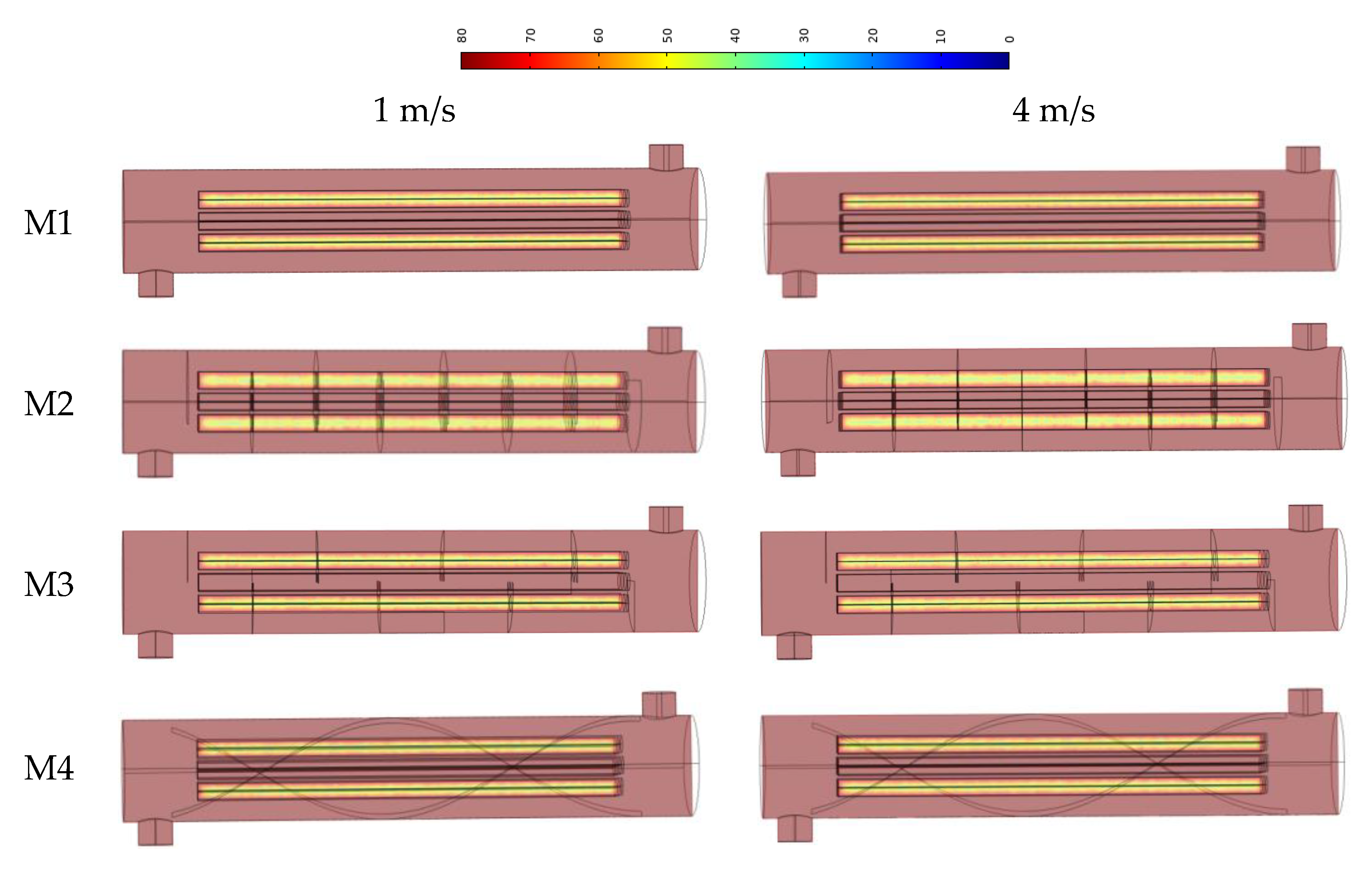
Figure 11 shows the PCM temperature distribution for Models 1–4 at the time where Model 1 reaches the phase transition temperature (57 °C).
The analysis of the temperature distribution in the heat store unit showed no significant differences in the temperature distribution at 65 min, which corresponds to the start of the PCM melting in the front part of the tube from M1. The application of baffles, and consequently the change of the flow pattern of the working medium, does not affect the temperature distribution in the PCM material.
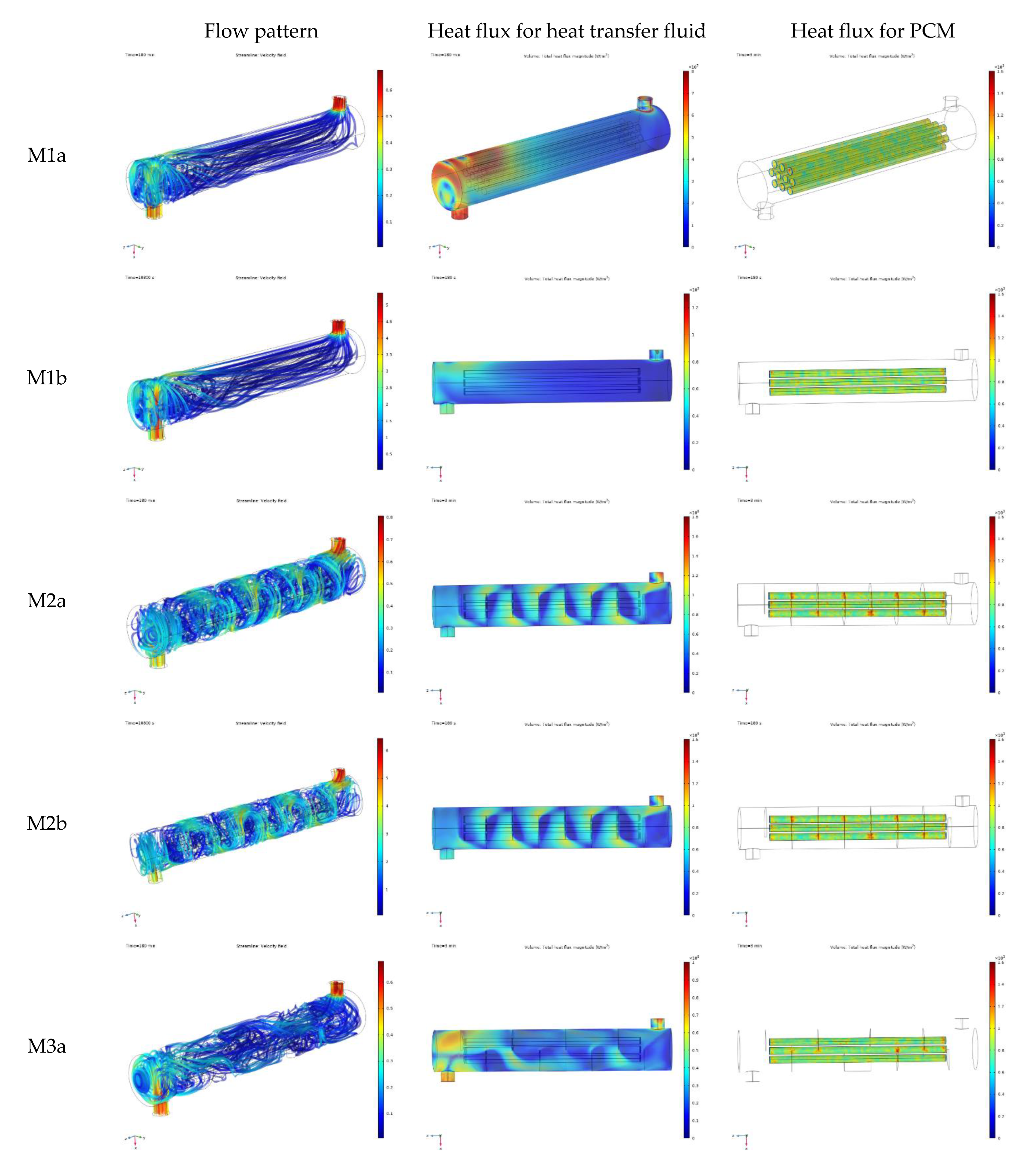
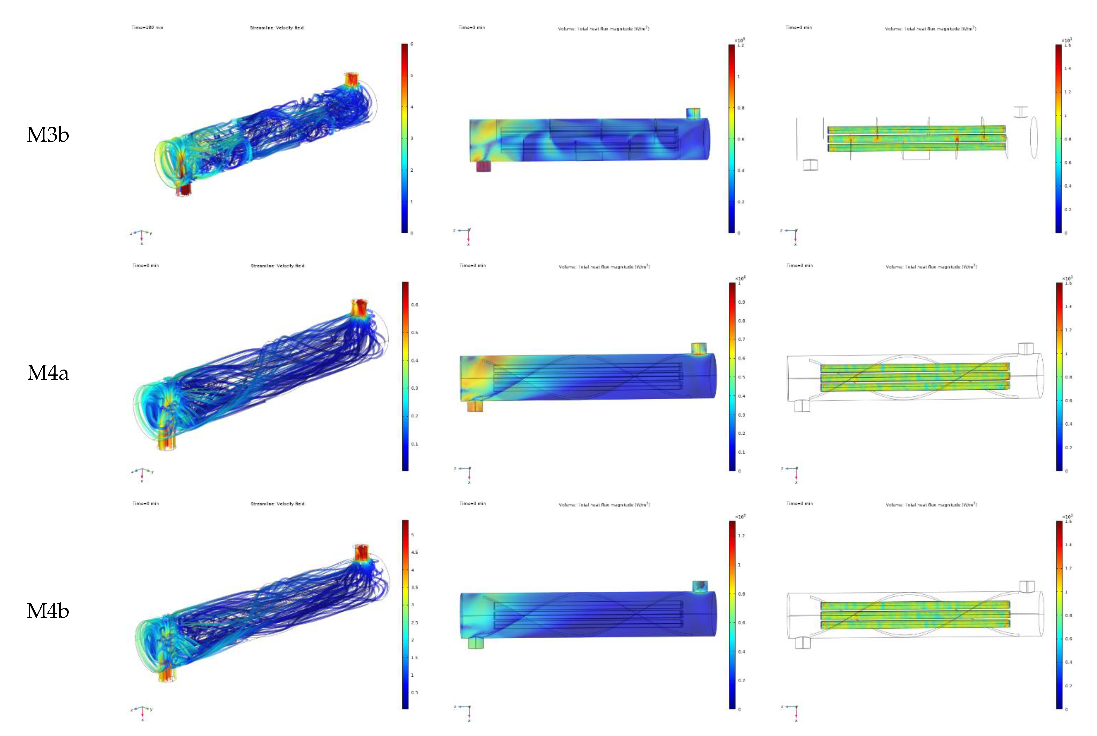
Figure 12 shows the flow pattern (streamlines with velocity-dependent color map), heat flux for heat transfer fluid and heat flux for phase change material. M1a represents model 1 with 1 m/s water velocity, while M1b represents model 1 with 4 m/s water velocity.
The analysis of the working fluid flow pattern and the heat flux distribution in the working fluid (water) shows strong correlation. The highest values of the heat flux are observable in the zone where the velocity reaches highest values. This, however, does not correspond to heat flux values in the PCM material. This effect is well visible when comparing M1 (no-baffle model) and M2 (half-circle baffles) models. In the case of M1, the highest heat flux values in the working fluid are observable around the water inlet zone, while the heat flux distribution in the PCM material remains relatively uniform. For M2, the highest heat flux values in the working fluid are visible around the baffles. In this case, the heat flux distribution in the PCM material is very similar to M1. Furthermore, there is no particular difference in the heat flux magnitude in the PCM for all studied models. This observation corresponds to only subtle differences in charging time. The analysis of the total heat flux for the PCM material inside the tubes explains the general difference between the heat exchanger and heat storage unit. The values of total heat flux for the PCM material do not show significant variations between considered models. This is observed due to low thermal conductivity of the PCM material and, as a result, the heat flux for the PCM is much lower than the heat flux for the HTF. As a result, variations of the heat flux for HTF do not affect the heat transfer in the PCM material. This means that tuning of the HTF flow pattern by the use of baffles or a similar element is applicable to shell and tube heat exchangers; however, it brings no effects in the case of heat storage units of the proposed design. It is expected that enhancing the heat transfer between HTF and the PCM material is possible by modifying the PCM–side design.
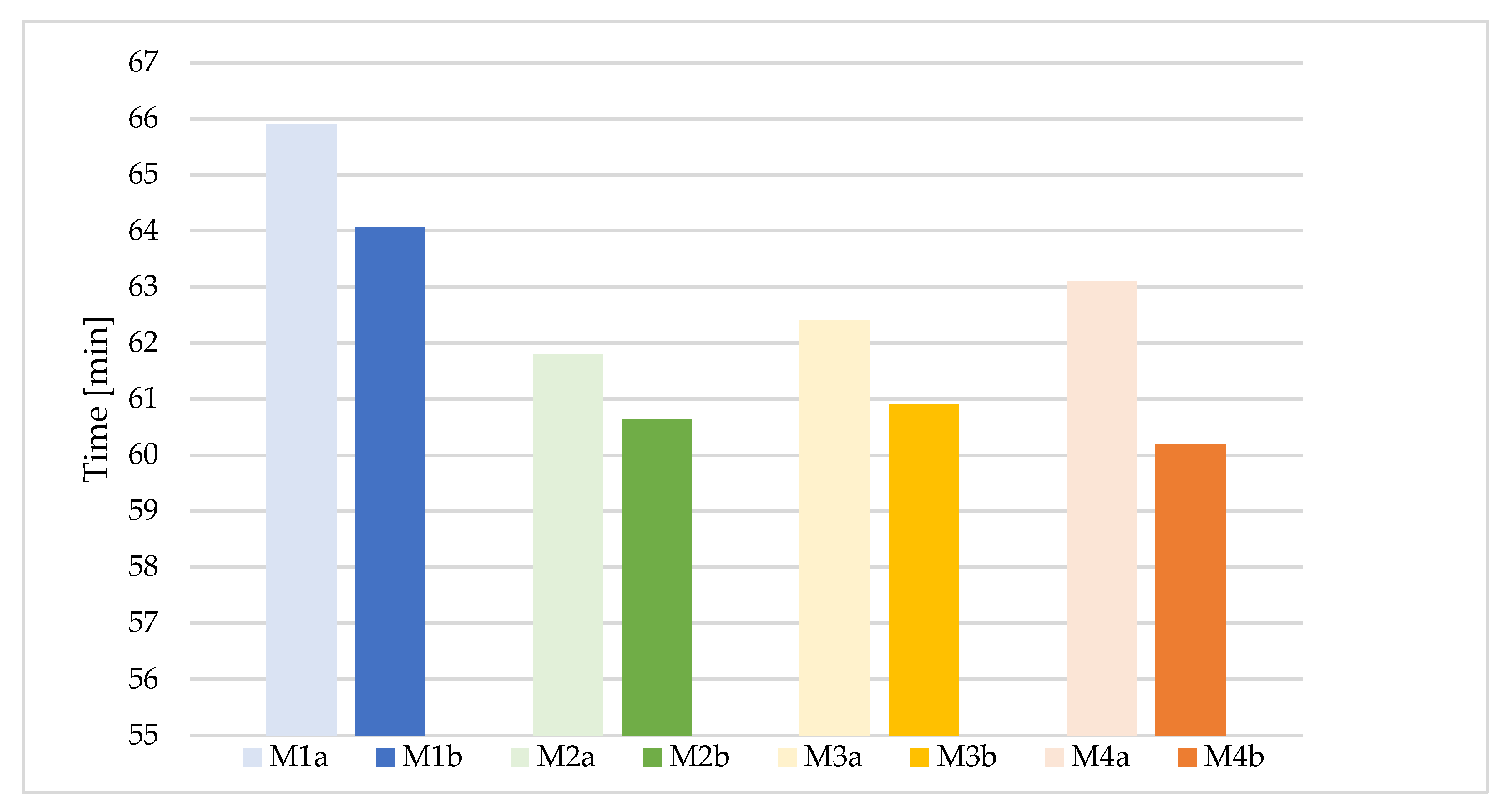
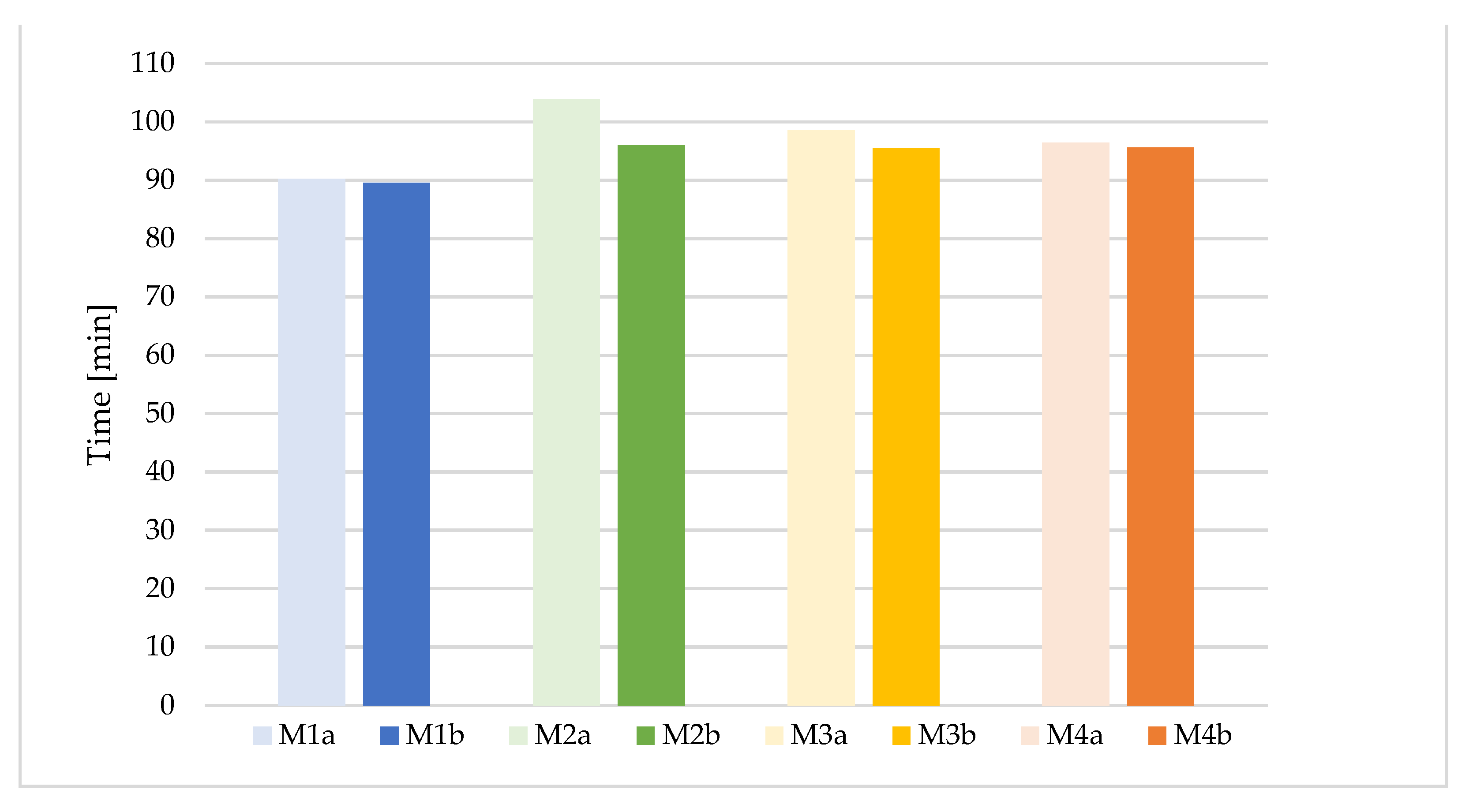
The analysis of the charging time involved two parameters: preheating time (Figure 13), which represents the time required to heat up the PCM material from initial temperature to the start of the PCM material melting (57 °C) and the charging time (Figure 14), which is the total time of the phase change process. It has been shown that increasing the flow velocity of the working fluid or the application of baffles bring only a slight reduction in the preheating time. The shortest preheating time was achieved using the model with a helical baffle and a heat transfer fluid flow of 4 m/s (M4b), while the longest preheating time was required in the case of the model without baffles and with a heat transfer fluid flow of 1 m/s (M1a). However, the shortest charging time was shown by the model without baffles (M1), regardless of the working fluid flow pattern.
4. Conclusions
The presented study has been performed to analyze the impact of the baffles on the charging time of a phase change heat storage unit, in the case of two values of heat transfer fluid stream. The geometry of the heat storage unit was analogous to a typical shell and tube heat exchanger, where the heat transfer fluid is directed to the shell part, while the tubes are filled with PCM material.
In the study, four types of heat storage unit geometry were taken into account. The differences included the shell part, in order to tune the flow pattern of the heat transfer fluid. The goal was to explore the impact of the flow pattern on the dynamics of the charging process in the case of large heat transfer fluid stream/velocity (4 m/s) and small heat transfer fluid stream/velocity (1 m/s). For this purpose, two types of simple baffles and one helical baffle ware analyzed.
The simulations of the charging process represented the 180 min time period. Initially, the temperature of the water, as the heat transfer fluid inside the shell, as well as the PCM tubes, was equal to 20 °C. During the charging process, the inlet water temperature was equal to 80 °C.
While the heat transfer fluid flow pattern was different for each model, the dynamics of the charging process were similar for all explored models. It was evidenced that in the case of PCM heat storage unit of this type, the application of baffles does not bring any observable benefits in terms of heat transfer enhancement and charging time decrease. Charging time was similar for all four studied heat storage units models, and the PCM temperature distribution inside 10 tubes did not show any significant differences.
The analysis of the total heat flux for the PCM material inside the tubes explains the general difference between the heat exchanger and heat storage unit. The values of the total heat flux for the PCM material do not show significant variations between the considered models. This is due to low thermal conductivity of the PCM material and, as a result, the heat flux for the PCM is much lower, comparing to heat flux for the HTF. As a result, variations of heat flux for HTF do not affect the heat transfer in the PCM material.
Consequently, it was found that the optimal design of heat storage units charged with a large fluid flow stream should not include additional elements such as baffles, which are typically expected to tune the working fluid flow and enhance the heat transfer. In the studied case, such an observation is not valid and does not reduce the charging time.
Author Contributions
Conceptualization, D.S.; Methodology, D.S.; Formal analysis, D.S.; Data curation, B.P.; Supervision, P.S. All authors have read and agreed to the published version of the manuscript.
Funding
This research received no external funding.
Conflicts of Interest
The authors declare no conflict of interest.
References
- Enterdata, Global Energy Statistica Yearbook. Available online: https://yearbook.enerdata.net/total-energy/world-consumption-statistics.html (accessed on 8 April 2021).
- Energy Storage Monitor. Latest Trends in Energy Storage; World Energy Council: London, UK, 2019. [Google Scholar]
- European Environment Agency. Energy in Europe—The Current Situation. Available online: https://www.eea.europa.eu/pl/sygna142y/sygnaly-2017/artykuly/energia-w-europie-2013-aktualna-sytuacja (accessed on 15 February 2021).
- Brendow, K. Global and Regional Coal Demand Perspectives to 2030 and Beyond Sustainable Global Energy Development: The Case of Coal. In Part I: Global Analysis, Proceedings of World Energy Council, Geneva, Switzerland, 7–8 December 2004; WEC: Geneva, Switzerland, 2004. [Google Scholar]
- Wang, G.; Blondeau, J. Multi-Objective Optimal Integration of Solar Heating and Heat Storage into Existing Fossil Fuel-Based Heat and Power Production Systems. Energies 2022, 15, 1942. [Google Scholar] [CrossRef]
- Faraj, K.; Khaled, M.; Faraj, J.; Hachem, F.; Castelain, C. A Summary Review on Experimental Studies for PCM Building Applications: Towards Advanced Modular Prototype. Energies 2022, 15, 1459. [Google Scholar] [CrossRef]
- Wojewódzki Fundusz Ochrony Środowiska i Gospodarki Wodnej w Łodzi. Instrukcja Rozliczania Kosztów Zadania Dofinansowywanego ze Środków WFOŚiGW w Łodzi dla Umów Zawartych od Stycznia. 2013. Available online: https://www.wfosigw.lodz.pl/dla-beneficjentow/podstawowe-informacje-o-dofinansowaniu/rozliczenia (accessed on 14 April 2021).
- Mechleri, E.; Dorneanu, B.; Arellano-Garcia, H. A Model Predictive Control-Based Decision-Making Strategy for Residential Microgrids. Eng 2022, 3, 9. [Google Scholar] [CrossRef]
- Alonso-Travesset, A.; Martin, H.; Cornas, S.; de la Hoz, J. Optimization Models under Uncertainty in Distributed Generation Systems: A Review. Energies 2022, 15, 1932. [Google Scholar] [CrossRef]
- Eydner, M.; Wan, L.; Henzler, T.; Stergiaropoulos, K. Real-Time Grid Signal-Based Energy Flexibility of Heating Generation: A Methodology for Optimal Scheduling of Stratified Storage Tanks. Energies 2022, 15, 1793. [Google Scholar] [CrossRef]
- Fernandes, D.; Pitie, F.; Caceres, G.; Baeyens, J. Thermal energy storage: “How previous findings determine current research priorities”. Energy 2012, 39, 246–257. [Google Scholar] [CrossRef]
- Mahamoudi, A.; Fazili, M.; Morad, M.R. A recent review of waste heat recovery by Organic Rankine Cycle. Appl. Therm. Eng. 2018, 143, 660–675. [Google Scholar] [CrossRef]
- Li, Z.; Lu, Y.; Huang, R.; Chang, J.; Yu, X.; Jiang, R.; Yu, X.; Roskilly, A.P. Applications and technological challenges for heat recovery, storage and utilisation with latent thermal energy storage. Appl. Energy 2021, 283, 116277. [Google Scholar] [CrossRef]
- Pereira, D.S.; Marques, A.C.; Fuinhas, J.A. Are renewables affecting income distribution and increasing the risk of household poverty? Energy 2019, 170, 791–803. [Google Scholar] [CrossRef]
- International Energy Agency. Technology Roadmap: Energy Storage; International Energy Agency: Paris, France, 2014. [Google Scholar]
- Papapertrou, M.; Kosmadakia, G.; Cipollina, A.; La Commare, U.; Micale, G. Industrial waste heat: Estimation of the technically available resource in the EU per industrial sector, temperature level and country. Appl. Therm. Eng. 2018, 138, 207–216. [Google Scholar] [CrossRef]
- Miró, L.; Gasia, J.; Cabeza, L.F. Thermal energy storage (TES) for industrial waste heat (IWH) recovery: A review. Appl. Energy 2016, 179, 284–301. [Google Scholar] [CrossRef] [Green Version]
- Independent Statistics and Analysis U.S. Energy Information Administration, Use of Energy Explained (14 May 2021). Available online: https://www.eia.gov/energyexplained/use-of-energy/ (accessed on 18 March 2022).
- Riffat, S.; Mempouo, B.; Fang, W. Phase change material developments: A review. Int. J. Ambient Energy 2015, 36, 102–115. [Google Scholar] [CrossRef]
- Alva, G.; Liu, L.; Huang, X.; Fang, G. Thermal energy storage materials and systems for solar energy applications. Renew. Sustain. Energy Rev. 2017, 68, 693–706. [Google Scholar] [CrossRef]
- Zhang, L.; Zhang, Z.; Yin, H. Comprehensive Study on Melting Process of Phase Change Material by Using Paraffin Coupled Finned Heating Plate for Heat Transfer Enhancement. Sustainability 2022, 14, 3097. [Google Scholar] [CrossRef]
- Agalit, H.; Zari, N.; Grosu, Y.; Faik, A.; Maaroufi, M. Synthesis of high temperature TES materials from silicates wastes for application in solar tower power plants. Sol. Energy Mater. Sol. Cells 2020, 218, 110763. [Google Scholar] [CrossRef]
- Daniarta, S.; Kolasiński, P.; Rogosz, B. Waste Heat Recovery in Automotive Paint Shop via Organic Rankine Cycle and Thermal Energy Storage System—Selected Thermodynamic Issues. Energies 2022, 15, 2239. [Google Scholar] [CrossRef]
- Pfleger, N.; Bauer, T.; Martin, C.; Eck, M.; Wörner, A. Thermal energy storage—Overview and specific insight into nitrate salts for sensible and latient heat storage. Beilstein J. Nanotechnol. 2015, 6, 1487–1497. [Google Scholar] [CrossRef] [PubMed] [Green Version]
- Zhao, J.; Gao, J.; Liao, J.; Zhou, B.; Bai, Y.; Qiang, T. An Experimental Study of the Heat Storage and the Discharge Performance and an Economic Performance Analysis of a Flat Plate Phase Change Material (PCM) Storage Tank. Energies 2022, 15, 4023. [Google Scholar] [CrossRef]
- Foong, C.W.; Hustad, J.E.; Løvseth, J.; Nydal, O.J. Numerical Study of a High Temperature Latent Heat Storage (200–300) Using Eutectic Nitrate Salt of Sodium Nitrate and Potassium Nitrate. In Proceedings of the COMSOL Users Conference, Paris, France, 17–19 November 2010. [Google Scholar]
- Dufly, J.P.; Trelles, J.J. Numerical simulation of porous latent heat thermal energy storage for thermoelectric cooling. Appl. Therm. Eng. 2003, 23, 1647–1664. [Google Scholar]
- Smykowski, D. Modelowanie procesów cieplno-przepływowych w akumulatorze ciepła z materiałem zmiennofazowym. Rynek Energii 2017, 5, 23–28. [Google Scholar]
- Kozak, P.; Andrzejczyk, R.; Muszyński, T. Badania eksperymentalne intensyfikacji wymiany ciepła wymiennika U-rurowego z wykorzystaniem turbulizatora helikoidalnego. Współczesne Problemy Elektrotechniki Oraz Rozwój I Ewaluacja Procesów Technol. 2017, 128–139. Available online: https://mostwiedzy.pl/pl/publication/badania-eksperymentalne-intensyfikacji-wymiany-ciepla-wymiennika-u-rurowego-z-wykorzystaniem-turbuli,142061-1 (accessed on 19 October 2022).
- FAMET GROUP. Available online: http://www.famet.com.pl/download/folders/heat-transfer-equipment.pdf (accessed on 17 February 2021).
- Wang, W.H.; Cheng, D.L.; Liu, T.; Liu, Y.H. Performance comparison for oil−water heat transfer of circumferential overlap trisection helical baffle heat exchanger. J. Cent. South Univ. 2016, 23, 2720–2727. [Google Scholar] [CrossRef]
- Klingenburg. Available online: http://www.klingenburg.pl/wiedza/cieplo-jawne-i-utajone/ (accessed on 10 February 2021).
- Allen, T. Simulation of Solidification and Cooling of a Casting Product Using Comsol Muliphysics. Master’s Thesis, Science in Engineering, Faculty od Engineering, Lund University, Lund, Sweden, 2019. Available online: https://lup.lub.lu.se/luur/download?func=downloadFile&recordOId=8977890&fileOId=8977895 (accessed on 10 November 2022).
- Rubitherm Technologies GmbH. Available online: https://www.rubitherm.eu/media/products/datasheets/Techdata_-RT64HC_EN_09102020.PDF (accessed on 11 August 2022).
- Mousavi Ajarostaghi, S.S.; Zaboli, M.; Javadi, H.; Badenes, B.; Urchueguia, J.F. A Review of Recent Passive Heat Transfer Enhancement Methods. Energies 2022, 15, 986. [Google Scholar] [CrossRef]
- Mellal, M.; Benzeguir, R.; Sahel, D.; Ameur, H. Hydro-thermal shell-side performance evaluation of a shell and tube heat exchanger under different baffle arrangement and orientation. Int. J. Therm. Sci. 2017, 121, 138–149. [Google Scholar] [CrossRef]
- Bayram, H.; Sevilgen, G. Numerical Investigation of the Effect of Variable Baffle Spacing on the Thermal Performance of a Shell and Tube Heat Exchanger. Energies 2017, 10, 1156. [Google Scholar] [CrossRef] [Green Version]
- Xiao, X.; Zhang, L.; Li, X.; Jiang, B.; Yang, X.; Xia, Y. Numerical investigation of helical baffles heat exchanger with different Prandtl number fluids. Int. J. Heat Mass Transfer. 2013, 63, 434–444. [Google Scholar] [CrossRef]
- Aadmi, M.; Karkri, M.; El Hammouti, M. Heat transfer characteristics of thermal energy storage of a composite phase change materials: Numerical and experimental investigations. Energy 2014, 72, 381–392. [Google Scholar] [CrossRef]
Figure 1.
Transverse turbulizer [29].
Figure 1.
Transverse turbulizer [29].


Figure 3.
Model 1.

Figure 4.
Model 2.

Figure 5.
Model 3.

Figure 6.
Model 4.

Figure 7.
Numerical mesh.

Figure 8.
Domains of the TES model: (a) first domain, (b) second domain, (c) third domain.

Figure 9.
Temperature over time at the front of the tube in Models 1–4 for the working fluid velocity of 1 m/s (a), and 4 m/s (b).
Figure 9.
Temperature over time at the front of the tube in Models 1–4 for the working fluid velocity of 1 m/s (a), and 4 m/s (b).

Figure 10.
Temperature over time in the center of the tubes in Models 1–4 for velocity 1 m/s (a), and 4 m/s (b).
Figure 10.
Temperature over time in the center of the tubes in Models 1–4 for velocity 1 m/s (a), and 4 m/s (b).

Figure 11.
Temperature distribution for Models 1–4 at the time where Model 1 reaches the phase transition temperature (57 °C).
Figure 11.
Temperature distribution for Models 1–4 at the time where Model 1 reaches the phase transition temperature (57 °C).

Figure 12.
Flow pattern (left column), heat flux in heat transfer fluid (middle column) and heat flux for PCM (right column) for all geometry variants (M1, M2, M3, M4) and two HTF flow velocity values: 1 m/s (a), 4 m/s (b).
Figure 12.
Flow pattern (left column), heat flux in heat transfer fluid (middle column) and heat flux for PCM (right column) for all geometry variants (M1, M2, M3, M4) and two HTF flow velocity values: 1 m/s (a), 4 m/s (b).


Figure 13.
Preheating time, which represents the time required to heat up the PCM material from initial temperature to the start of the PCM material melting (57 °C) for all models and working fluid velocity magnitudes.
Figure 13.
Preheating time, which represents the time required to heat up the PCM material from initial temperature to the start of the PCM material melting (57 °C) for all models and working fluid velocity magnitudes.

Figure 14.
Charging time, which is the total time of the phase change process for all models and working fluid velocity magnitudes.
Figure 14.
Charging time, which is the total time of the phase change process for all models and working fluid velocity magnitudes.


Table 1.
Properties of the PCM used [34].
Table 1.
Properties of the PCM used [34].
| Parameter | Symbol | Unit | Value |
|---|---|---|---|
| phase transition temperature range | - | °C | 57–72 |
| heat capacity | ∆H | kJ/kg | 250 |
| specific heat at constant pressure | J/(kg∙°C) | 2000 | |
| solid phase density | qs | kg/m3 | 880 |
| liquid phase density | ql | kg/m3 | 780 |
| heat transfer coefficient | α | W/(m2∙°C) | 50 |
| thermal conductivity | λ | W/(m∙°C) | 0.2 |
| maximum operating temperature | °C | 95 | |
| dynamic viscosity | µ | kg/(m·s) | 0.0358 |
| coefficient of thermal expansion | 1/°C | 0.000778 |
Table 2.
Parameters of the mesh.
| Parameter | Model 1 | Model 2 | Model 3 | Model 4 |
|---|---|---|---|---|
| number of elements | 469399 | 568157 | 603080 | 513380 |
| minimum element size | 0.108 | 0.108 | 0.108 | 0.108 |
| maximum element size | 0.513 | 0.513 | 0.513 | 0.513 |
| maximum element growth rate | 1.7 | 1.7 | 1.7 | 1.7 |
| curvature factor | 0.8 | 0.8 | 0.8 | 0.8 |
| resolution of narrow region | 0.3 | 0.3 | 0.3 | 0.3 |
Table 3.
Computational parameters.
| Parameter | Unit | Value |
|---|---|---|
| Inlet water velocity | m/s | (a) 1 (b) 4 |
| Inlet water temperature | °C | 80 |
| Initial temperature (all domains) | °C | 20 |
Table 4.
Boundary conditions.
| Parameter | Value |
|---|---|
| External walls | Thermal insulation, –n · q = 0 |
| Shell inlet | Normal inflow velocity, u0 Upstream temperature, Tustr |
| Shell outlet | Pressure, p0 = 0 |
| HTF–PCM interface | Thin layer, thermally thick approximation Lth = 3 · 10–3 m |
| Properties of HTF–PCM thin layer | λ = 16.3 W/m·°C, ρ = 7990, Cp = 500 J/kg·°C |
Publisher’s Note: MDPI stays neutral with regard to jurisdictional claims in published maps and institutional affiliations. |
© 2022 by the authors. Licensee MDPI, Basel, Switzerland. This article is an open access article distributed under the terms and conditions of the Creative Commons Attribution (CC BY) license (https://creativecommons.org/licenses/by/4.0/).
Share and Cite
MDPI and ACS Style
Pytlik, B.; Smykowski, D.; Szulc, P. The Impact of Baffle Geometry in the PCM Heat Storage Unit on the Charging Process with High and Low Water Streams. Energies 2022, 15, 9349. https://doi.org/10.3390/en15249349
AMA Style
Pytlik B, Smykowski D, Szulc P. The Impact of Baffle Geometry in the PCM Heat Storage Unit on the Charging Process with High and Low Water Streams. Energies. 2022; 15(24):9349. https://doi.org/10.3390/en15249349
Chicago/Turabian StylePytlik, Beata, Daniel Smykowski, and Piotr Szulc. 2022. "The Impact of Baffle Geometry in the PCM Heat Storage Unit on the Charging Process with High and Low Water Streams" Energies 15, no. 24: 9349. https://doi.org/10.3390/en15249349
Note that from the first issue of 2016, this journal uses article numbers instead of page numbers. See further details here.