Article

Flyback Photovoltaic Micro-Inverter with a Low Cost and Simple Digital-Analog Control Scheme

1
Department of Electrical Power Engineering, Electrical Engineering Technical College, Middle Technical University, Baghdad 10001, Iraq
2
Electronic and Control Engineering Department, Technical Engineering College Kirkuk, Northern Technical University, Kirkuk 00964, Iraq
3
Biomedical and Electronics Engineering, Faculty of Engineering and Informatics, University of Bradford, Bradford BD7 1DP, UK
*
Author to whom correspondence should be addressed.
Energies 2021, 14(14), 4239; https://doi.org/10.3390/en14144239
Submission received: 18 June 2021 / Revised: 6 July 2021 / Accepted: 12 July 2021 / Published: 14 July 2021

Abstract

:
The single-stage flyback Photovoltaic (PV) micro-inverter is considered as a simple and small in size topology but requires expensive digital microcontrollers such as Field-Programmable Gate Array (FPGA) or Digital Signal Processor (DSP) to increase the system efficiency, this would increase the cost of the overall system. To solve this problem, based on a single-stage flyback structure, this paper proposed a low cost and simple analog-digital control scheme. This control scheme is implemented using a low cost ATMega microcontroller built in the Arduino Uno board and some analog operational amplifiers. First, the single-stage flyback topology is analyzed theoretically and then the design consideration is obtained. Second, a 120 W prototype was developed in the laboratory to validate the proposed control. To prove the effectiveness of this control, we compared the cost price, overall system efficiency, and THD values of the proposed results with the results obtained by the literature. So, a low system component, single power stage, cheap control scheme, and decent efficiency are achieved by the proposed system. Finally, the experimental results present that the proposed system has a maximum efficiency of 91%, with good values of the total harmonic distortion (THD) compared to the results of other authors.

1. Introduction

1.1. Background and Motivation

In recent years, renewable energy sources such as solar and wind, which are environmentally clean and free, have been receiving strong attention and emphasis throughout the world [1,2]. In renewable energy systems based on solar energy, Photovoltaic modules are the interface with the primary energy [3,4,5].
Although PV modules are a key element in energy conversion, they will often be looked at as just a source of electrical energy. Over an electrical energy source, they have a peculiar behavior related to solar irradiance and temperature [6]. Besides, to reduce prices, the durability of PV modules is an important factor in the popularity of renewable energy. A PV module does not contain any moving parts, as opposed to some of the other renewable energy sources such as wind. A long lifetime is therefore guaranteed, without almost any tear, wear, and maintenance. Nowadays, more and more complex PV modules are studied for the designing and implementation of efficient PV system strategies [7,8,9,10].

1.2. Literature Review and Research Gap

Several methods to arrange the solar PV modules are used to provide sufficient PV power to the grid-connected inverter, which in turn influences the cost of installation and inverter efficiency. Mainly, three general types of grid-connected inverter schemes depend on the solar PV module configuration: central inverters, string inverters, and micro-inverters are studied. In recent years, the modern technology of micro-inverter that consists of a single PV module integrated with an interactive inverter has been proposed and reviewed [11,12,13]. With many advantages, over conventional inverters, the micro-inverter is considered a popular solution for grid-connected inverters with PV systems [14,15].
However, a flyback micro-inverter was proposed for low PV power applications based on the DC/DC flyback converter. In this topology, the number of power stages depending on the type of connection of switches in the DC/AC stage that are integrated with the utility grid can be designed as a single-stage or two-stage inverter [16]. The two topologies of flyback micro-inverters can be implemented which are a center-tapped three-winding topology, and two-phase interleaved flyback topology based on the high-frequency transformer (HFT) [17].
Y. H. Kim et al. [18] presented the two-phase interleaved flyback micro-inverter with a new control strategy. It predicts that using a two-phase interleaved type instead of a center-tapped transformer type can increase the transferred output power to the grid. Therefore, a stable operation and higher efficiency are achieved. Although higher efficiency is achieved, the control strategy has the drawback of being complicated and expensive. In general, the dominant losses that occurred in the switching operation decrease the overall efficiency of the interleaved flyback inverter that operates in discontinuous conduction mode (DCM) or boundary conduction mode (BCM) control strategies. Therefore, the authors in [19] proposed a new hybrid control strategy based on one- and two-phase DCM in order to achieve higher efficiency at light load or heavy load conditions by decrease the switching losses.
Z. Zhang et al. [20] applied the BCM control strategy on two parallel flyback converters in order to increase the output power level of what is injected into the utility grid, and then achieving higher efficiency. Unfortunately, the main drawback in this work is the higher total harmonic distortion (THD) content in the output current. Also, several studies are presented to combine the advantages of both the DCM and BCM control strategies [21,22,23]. In addition, the continuous conduction mode (CCM) as a simple control scheme with low cost is proposed in [24,25]. The main problem in this strategy is the right half-plane (RHP) zero that occurs in the CCM region operation which may cause poor power quality and higher THD in output current. Moreover, different types of flyback topologies operated with DCM, BCM, and CCM strategies were proposed and reviewed [26,27,28,29,30,31,32]. Moreover, a new flyback inverter topology was proposed by H. Hu et al. [32,33] to increase the long lifetime of the flyback inverter by using a small film capacitor. Although in [32,33] no switching losses regarding the system efficiency are mentioned, the switching losses across the decupling device circuit will reduce the system efficiency. Furthermore, higher stress for switching devices due to using a smaller capacitor may result in more losses and lower efficiency.
In summary, the type of control scheme used in the flyback micro-inverter is very important as it directly affects the cost and conversion efficiency of the system. As mentioned before, several digital control schemes use expensive controllers. This makes the control circuit high-cost which also requires more digital devices to implement the overall control scheme.

1.3. Aims and Contributions

In this paper, a low cost digital-analog control scheme is presented that realizes a single-stage flyback micro-inverter. The main part of the proposed control scheme is the low cost ATMega microcontroller. Also, we use a simple analog circuit to track the zero-crossing detection of the grid voltage and provides suitable signal pulses to the semiconductors of the inverter. Also, the proposed control scheme is compared with other topologies that used the different controllers [18,20,32,33]. The research is presented as follows: Section 2 covers the flyback micro-inverter and its analysis; design of transformer and system parameters is presented in Section 3. The proposed digital-analog control scheme is presented in Section 4. The simulation and experimental results are presented in Section 5, while the conclusion is presented in Section 6.

2. Flyback Micro-Inverter and Its Analysis

A Flyback PV micro-inverter is a single-stage inverter with a simple structure circuit. With many functions over multi-stage inverters, the flyback micro-inverter provides DC/AC conversion with isolation between the input side and output side; it raises the DC input voltage level to AC utility grid voltage level [19,20,34]. This topology transfers the output power from a PV module to the utility grid through the two secondary windings of a center tap high-frequency transformer alternatively during the half period of the AC sinusoidal wave of the utility grid [32].
Figure 1 shows the flyback topology circuit used in this work which consists of an input DC source (PV module), decoupling capacitor Cin, HFT with one primary and center-tapped two secondary windings, and one switch in the PV side module, two switches in the grid side with two diodes, and an output filter. Moreover, the main switch SPV is operated with high switching frequency (about 30 kHz), while the secondary switches, SAC1 and SAC2 are operated with a grid frequency (50 Hz). The simulation and practical implementation of the proposed work depend on the following main specifications:
Input voltage from PV module is 25–33 V;
RMS grid voltage is 220 V;
Grid frequency is 50 Hz, and;
Maximum transferred power to the grid is 120 W.

2.1. Analysis of Duty Cycle and Turns-Ratio

The selection of turns-ratio   N   ( N s / N p ) of the flyback transformer, and the selection of duty cycle D are interrelated as each one depends on the other [26]. Therefore, the value of D is determined based on the value of N, which is assumed to be determined as the starting point for designing the flyback inverter. The value of N is defined as follows:
N V ^ g V pv , min
where V ^ g and V pv , min are the peak value of grid voltage and the minimum value of the PV module voltage, respectively. N is the transformer turns-ratio. The proposed micro-inverter is designed to operate with DCM, therefore, the magnetizing current must be limited, so that this current falls to zero when the main switch, S PV becomes OFF, and before the new switching cycle begins. Thus, the critical case situation occurs when the inverter operates at a peak duty ratio D max . Also, while the main switch S PV is ON, the DC input voltage across the primary winding is the same PV module voltage and can be expressed as follows [35,36]:
V pv = L m d i p ( t ) dt  
where L m is the magnetizing inductance. The primary current increases linearly as in the following [28,29,30,31]:
I p = V pv   T on L m = V pv   D   T s L m  
where I p is the primary current, and D is the duty cycle.
To stay always under DCM operation, the OFF-time interval, T off , must be smaller than the difference between the total time interval and the ON time interval,   T on , as given below [28,37]:
T off , max   ( T s T on , max   )
where T off , max is the OFF time of S PV and T on , max is the ON time of S PV , which can be expressed as:
T on , max = D max   T s = D max f s  
where fs is the switching frequency. By substituting Equation (5) into Equation (3) we reach the following expression:
I ^ p = V pv   D max L m   f s  
and, the instantaneous grid voltage can be written as [29]:
v g ( t ) = V ^ g   sin ω t  
where ω is the line frequency in rad/sec. The primary current I p   drops to zero when S pv   turns OFF, and the energy stored in the magnetizing inductance is transferred to the grid. Since during this time the voltage across the secondary winding is reflected on the primary, it can be written as [37]:
  v grid ( t ) N = L m d i p ( t ) d ( t )  
Therefore, the maximum OFF time T off , max can be expressed as:
T off , max = L m   I ^ p   N   V ^ g    
Substituting Equation (6) into Equation (9) gives:
T off , max = V pv   N   D max     V ^ g   f s  
The values for N and D max   should be selected so that the micro-inverter remains in DCM. By substituting Equation (10) into Equation (4), the following equation is obtained:
V pv   N   D max     V ^ g   f s     ( T s T on , max )  
By dividing both sides of this equation by T on , max :
V pv   N   D max     V ^ g   f s   T on , max   ( T s T on , max 1 )  
V pv   N     V ^ g     ( 1   D max   1 )  
N   V ^ g   V pv   ( 1 D max   1 ) 1  
Alternatively, this equation can be simplified to give the peak value of the duty ratio as follows [28,31,37]:
D max     1   V pv N     V ^ g + 1  

2.2. Analysis of Magnetizing Inductance

The most important factor required to be carefully treated in DCM operation is the magnetizing inductance value, L m of the flyback transformer. If L m is low, a high peak magnetizing current in the primary winding will be generated, and this may cause damage to the main switch [28]. On the other hand, when the value of L m is high, a magnetizing current will work in the CCM mode. Therefore, an appropriate L m value should be chosen very carefully as is presented in this section.
However, the value of L m that stores sufficient energy in the transformer winding depends on the value of the output power P o , which is extracted from the micro-inverter. If the micro-inverter is assumed to be ideal, then the power balance equation under DCM condition can be expressed as follows [33,34]:
V pv   I pv = 1 2 V ^ g I ^ out  
where I ^ out is the peak value of output current. Hence, the input power of the micro-inverter is equal to the AC output power that is fed to the utility grid, which can be written as:
P i = P o .  
Since the input voltage from the PV module is DC, then the input power of the flyback micro-inverter is dependent on the input RMS current [34]. The real RMS value of this current is the average over a grid period. As a result, the input power is dependent on the input average current I in , avg as follows [29,34]:
P i = V pv   I in , avg  
For this reason, deriving the expression between L m and I in , avg will achieve the objective of finding the relationship between the magnetizing inductance and input power.
So, the average current can be derived as in Equation (19) [34]:
I in , avg = 1 T grid / 2 0 T grid / 2   I p ( t )   dt  
where T grid is the fundamental period for the grid (20 ms). In addition, the primary current of the flyback micro-inverter is the summation of triangular pulses as follows:
I in , avg = 1 T grid / 2   i = 1 n 0 T on   I p ( t )   dt  
where i = 1 , 2 , 3 n , and n is the number of switching cycles per half AC grid line cycle so that,
n = T grid / 2 T s  
The integration of one triangular pulse from these pulses for an i th switching cycle can be written as:
0 T on   I p ( t )   dt = 0 T on   V pv   t L m   dt  
Moreover, the ON time of the main switch S PV for the switching cycle when the primary current is at its maximum value was given in Equation (6). Therefore, the peaks of the maximum current follow a sinusoidal envelope, and then after, the duty ratio can be written in terms of a sinusoidal as follows [30,34]:
T on = T s   D max   sin ω t ;   ω t   [ 0   ,   π   ]
I in , avg = V pv   D max 2   4   f s L m    
Substituting this equation into Equation (18) gives,
P i = P o = V pv 2   D max 2   4   f s L m    
The flyback micro-inverter usually supplies the utility grid, therefore, the power expression in Equation (25) can be written in terms of utility grid RMS voltage as follows:
V g , rms = V ^ g 2 .  
For this reason, the numerator and denominator of Equation (25) are multiplied by ( V g , rms 2 ) and rearranged so it can be written as:
P o = V pv 2   D max 2   V g , rms 2   4   f s L m   ( V ^ g 2 ) 2  
As a result, the output power that is transferred to the grid can be written as follows [34]:
P o = 1 2   ( V pv V ^ g ) 2   D max 2   V g , rms 2   f s L m   = 1 2 λ 2   D max 2   g l   V g , rms 2  
where λ = V pv V ^ g , and g l = 1 f s L m . By rearranging Equation (28), the relation between magnetizing inductance, L m , and the transferred rated output power, P o can be written as:
L m = 1 2 λ 2   D max 2   V g , rms 2 P o   f s    

3. Design of Transformer and System Parameters

The principle of flyback DCM micro-inverter is based on the stored energy in magnetizing inductance during the “ON period” and the discharge of the energy to the grid during the “OFF period”. Therefore, all the energy stored in the magnetizing inductance is transferred to the utility grid before the next charging period occurs [34].
The primary current is a rectified sine wave, therefore, a relatively high DC current component will flow in the primary winding, thus a high DC magnetizing force will occur which may cause saturation. For this reason, a ferrite core is a suitable choice [36]. Also, the skin depth is known as the distance below the surface, where the current density has fallen to 1⁄ε or 37 percent of its value at the surface. The skin depth in centimeters can be written as [35,36]:
ε = 6.62 f s .  
When selecting the wire for high frequencies, we need to select a wire such that the relationship between the AC resistance and the DC resistance is unity. For switching frequency f s equal to 30 kHz, the skin depth will be ε = 0.03822 cm, then the wire diameter D w and cross-section area can be calculated from the following equations,
D w = 2 ε   cm  
A w = π   D w 2 4  
As a result, we have a cross-section area of 4.6 × 10 3   cm 2 . Moreover, from the wire table of American Wire Gauge (AWG) specifications, we used number 19 that has a bare wire area of 5.18 × 10 3   cm 2 . Furthermore, the transformer ratio can be calculated from Equation (1), N 10 , and the total switching period T S = 33.33   μ s . The maximum duty cycle can be calculated from Equation (15) as D max 0.5 for T o , max = 16.6   μ s . Also, The required magnetizing inductance L m = 18.8   μ H .
However, the energy handling capability, E in watt-seconds, can be determined by using the following Equation [36]:
E = L m   I ^ p 2   2  
Therefore, the calculated energy handling is E = 0.01   J . As a result, we select the ferrite core type E55/28/2-3C90, which is manufactured by the company Ferroxcube [38].
Finally, the number of primary and secondary turns are calculated as in [36], so we have N p = 21   t urns, and N s 2 = N s 1 = 196 turns.

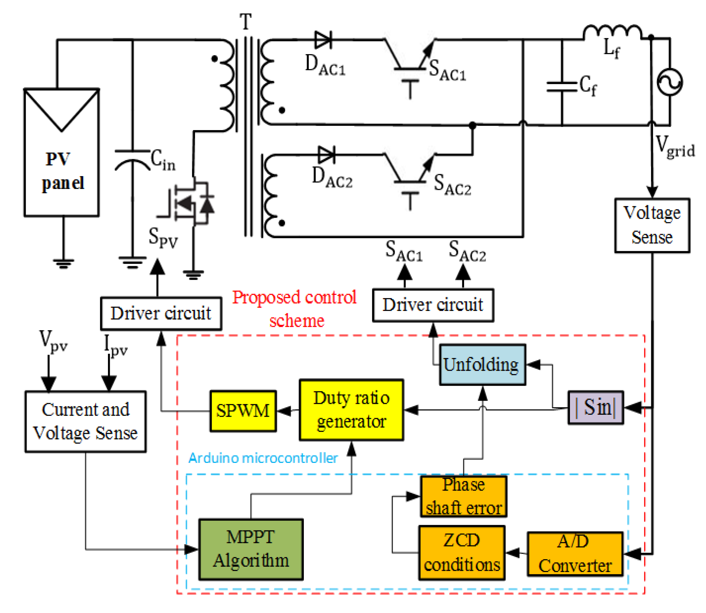
4. Proposed Digital-Analog Control Scheme

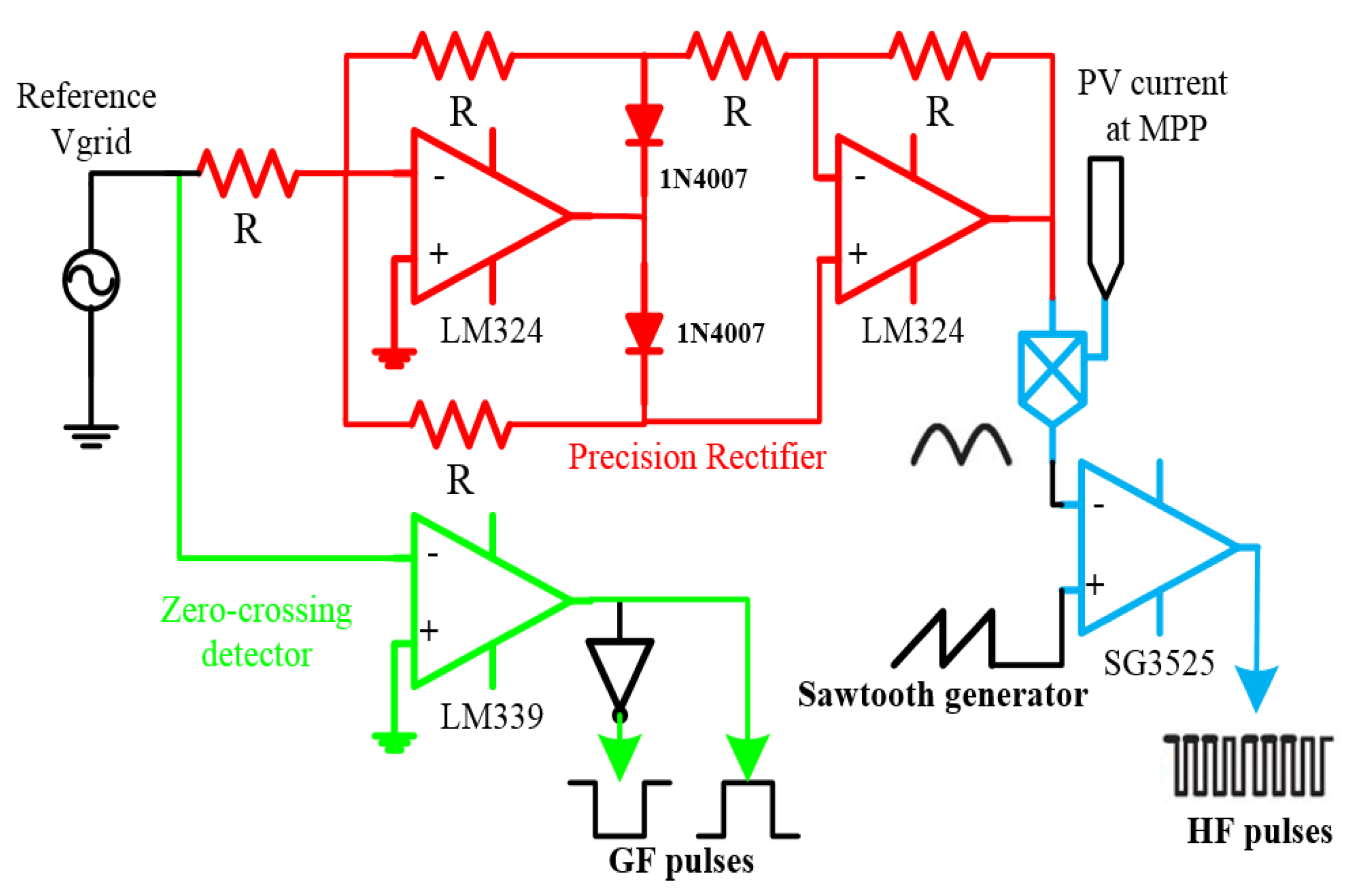
4.1. Simple Analog Control Circuit

The proposed analog control circuit is shown in Figure 2. This circuit consists of three parts, a precision rectifier circuit, pulse width modulation (PWM) comparator, and zero-crossing detector. As observed, the precision rectifier circuit is implemented using the operational amplifier type LM324 in order to generate the rectified sine wave from the grid voltage. This signal is regulated by the MPPT algorithm to produce the reference signal of the primary current I p * which is compared with the high switching frequency signal   S ( t ) .
As a result, the SPWM pulses (HF pulses) are obtained to turn on the main MOSFET S PV through a simple comparator type SG3525. As a result, the main MOSFET S PV is controlled by tracking the reference value of the primary current. So, the peak spike voltage across S PV in the “OFF time” period is adjusted. Moreover, the zero-crossing detector using a low cost comparator (LM339) is used to track the reference grid voltage. Furthermore, the IGBTs on the grid side, S AC 1 and S AC 2 are triggered reciprocally according to the grid voltage polarity. The reference grid voltage is compared with the ground to turn on the S AC 1 which is responsible for the positive cycle, while other IGBTs are turned on by inverting the pulses of S AC 1 . In addition, when the reference voltage of the grid is altered from the negative to the positive, this will be predicated by the input pins of the Arduino board, therefore, the phase shaft error between the output current and grid is indicated and the synchronization process is implemented as presented in Figure 1.

4.2. Digital Control Circuit

The main objective of the digital control scheme is to obtain the MPP from the PV module at different weather conditions by a program embedded in the ATMega 328 microcontroller of the Arduino Uno board. In this paper, a simple P&O-MPPT algorithm with a digital PI controller is implemented to track the MPP of the PV panel. The ATMega 328 microcontroller represents the brain of the entire control scheme, it converts the analog values from the sensors into digitals and produces two output channels to control the main MOSFET and detect the phase shaft error between the injected current and the grid. Also, a simple code algorithm is used and loaded through the Arduino IDE environment. Table 1 shows the price of the proposed control scheme components. As observed, the budget of the control components is cheap compared with the one used in [18,20].

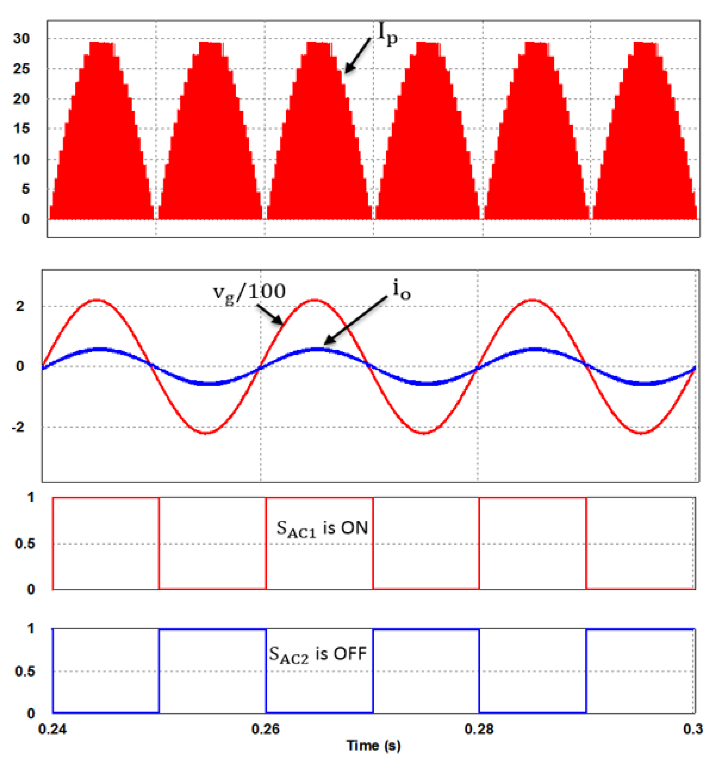
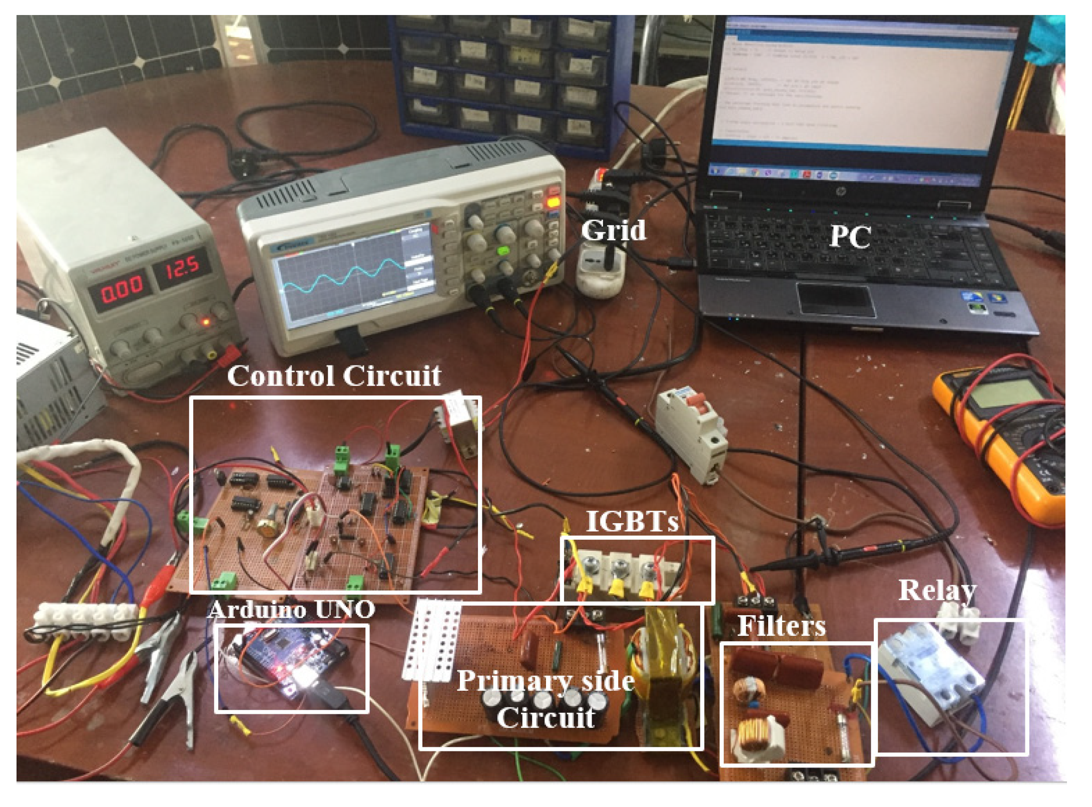
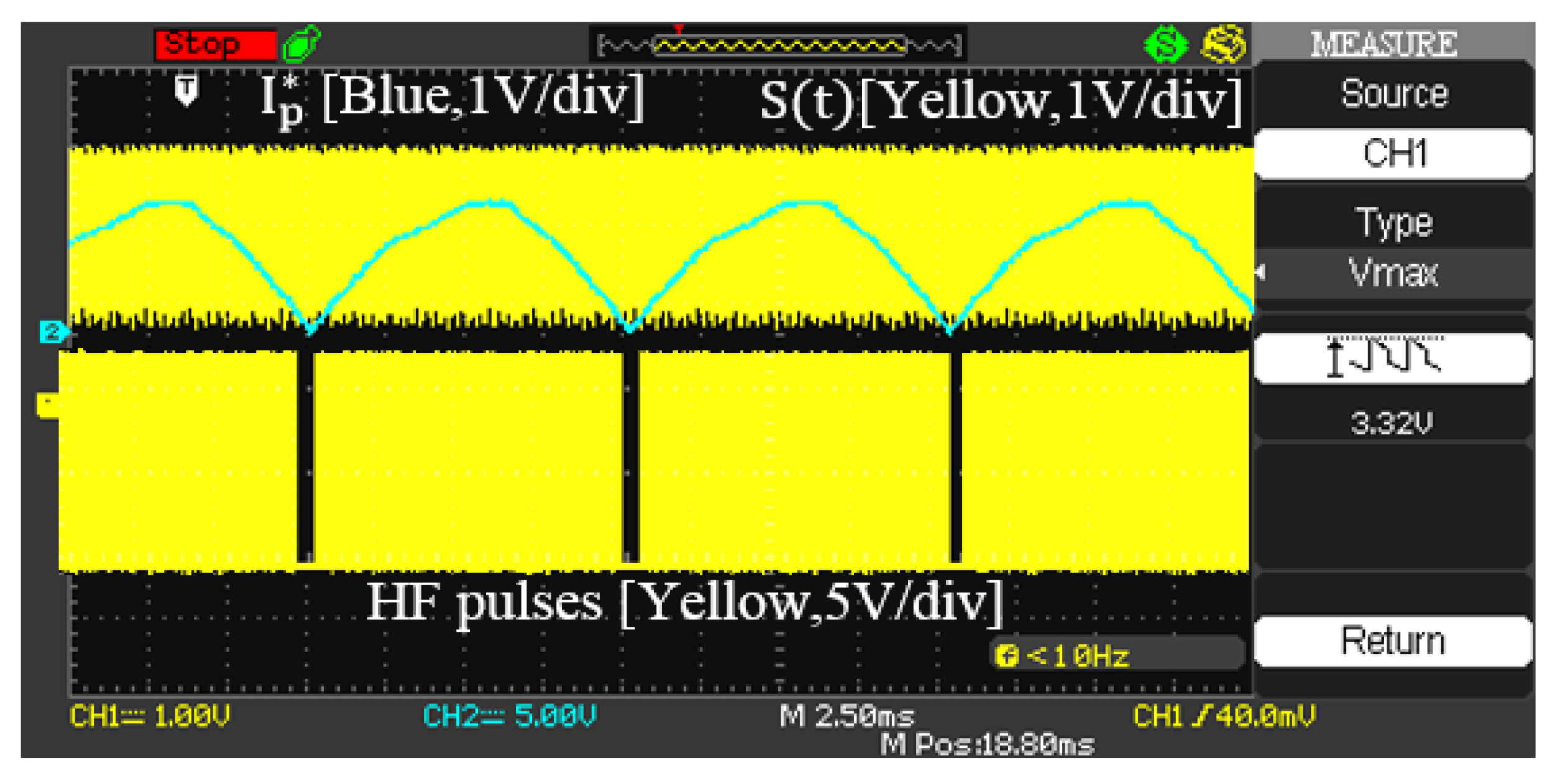
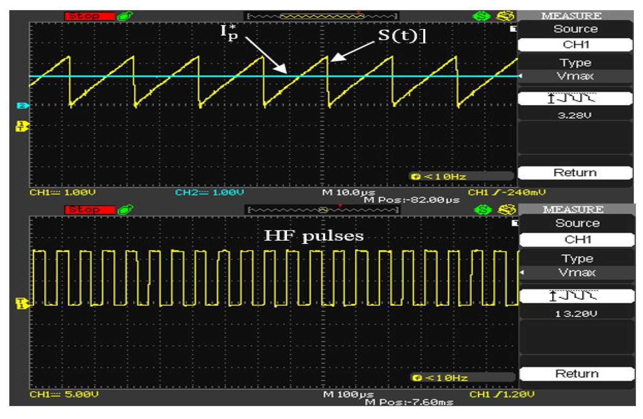
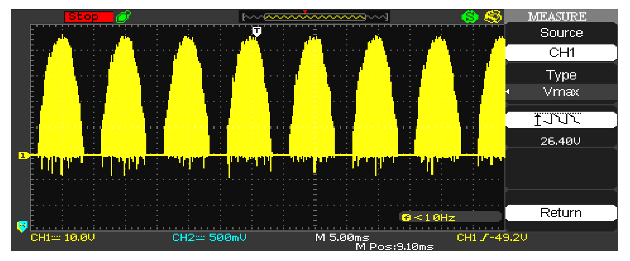
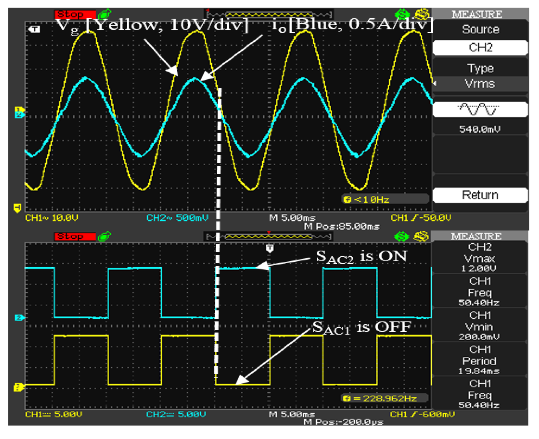
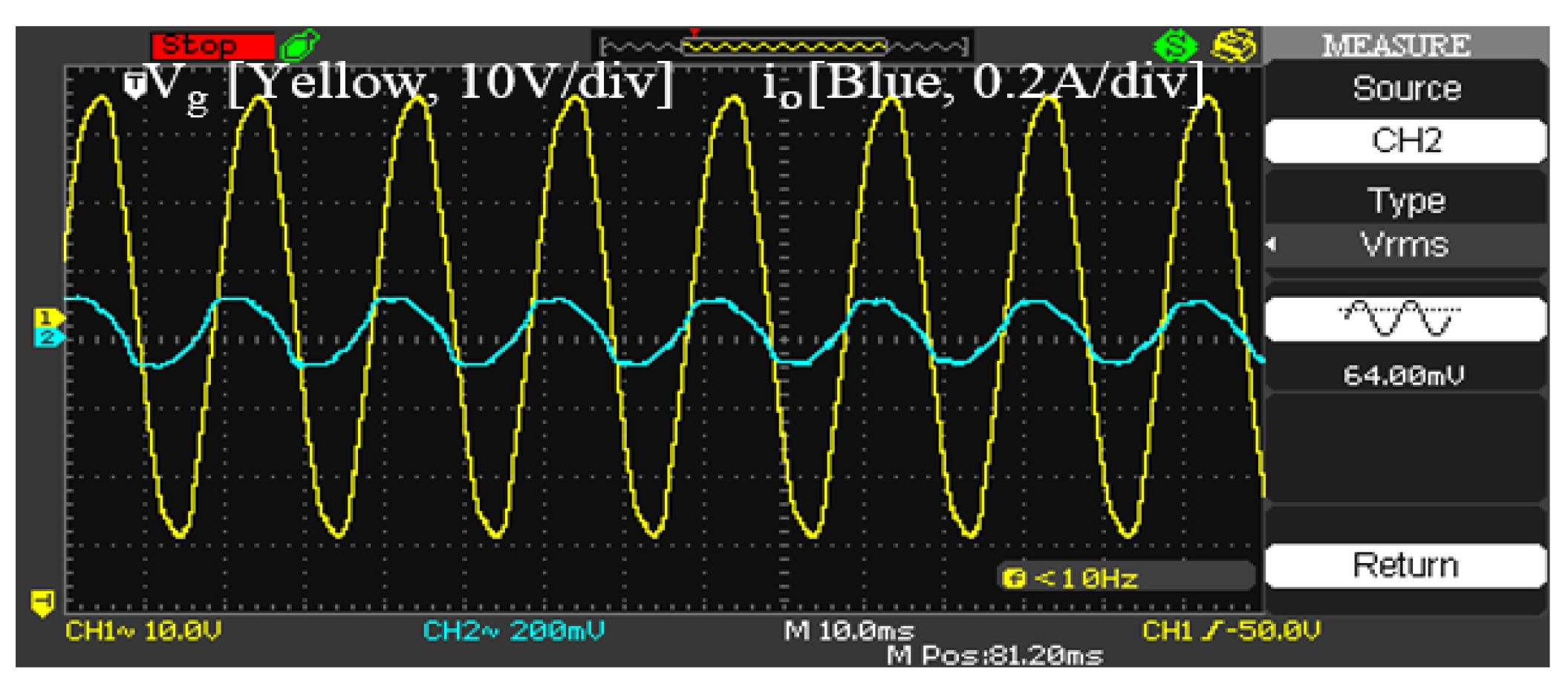
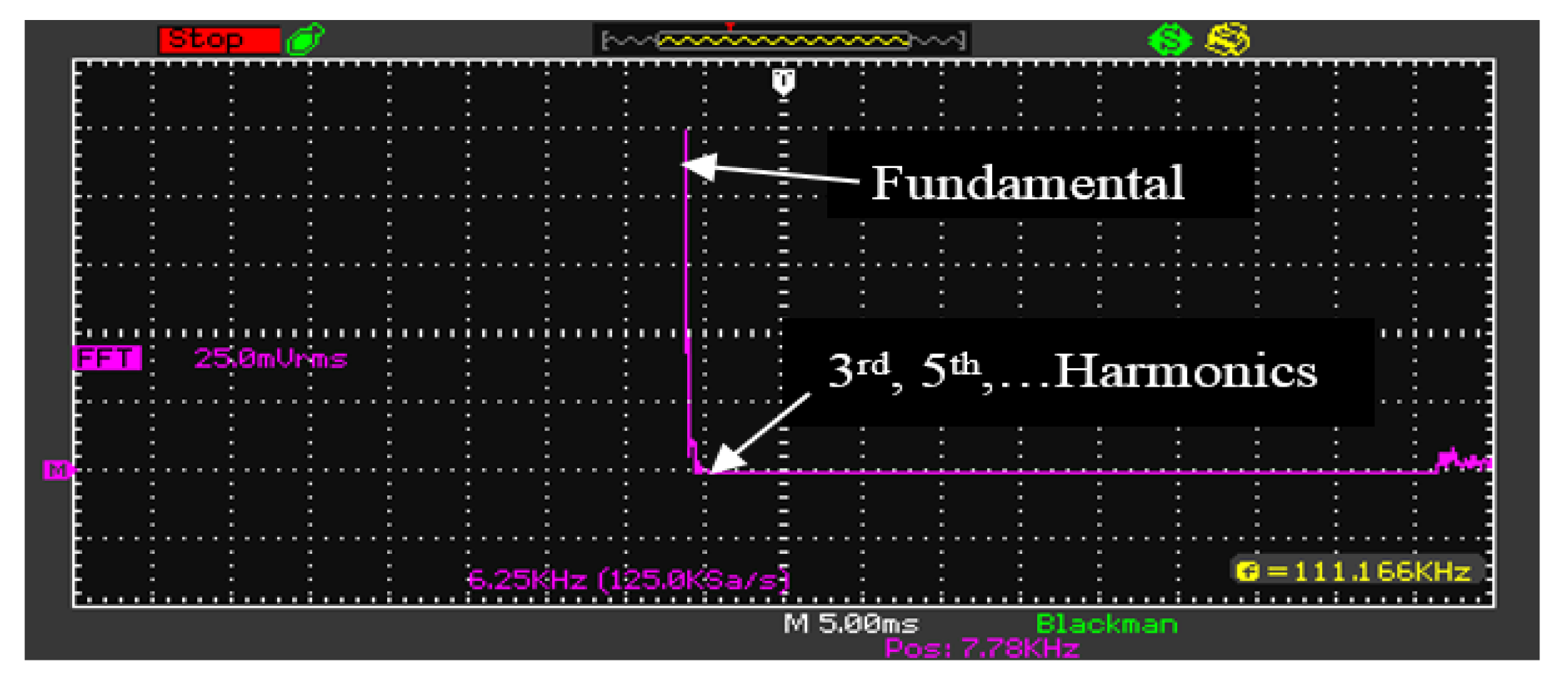
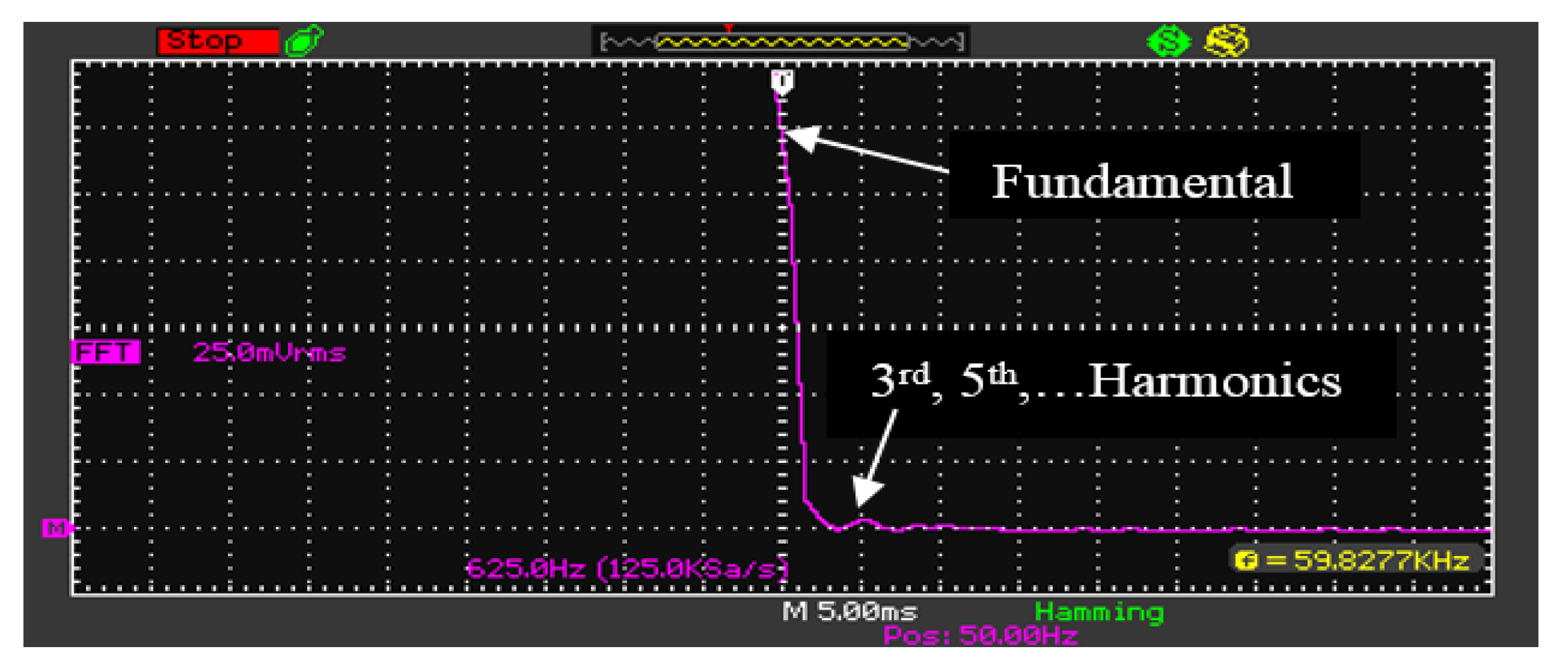
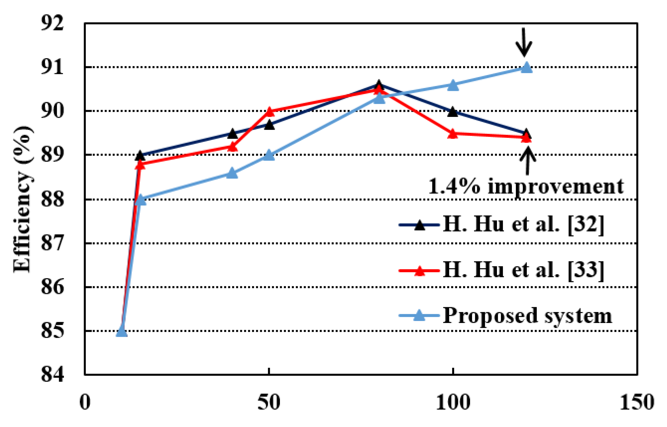
5. Simulation and Experimental Results

To verify the proposed control scheme, the PSIM software was used for simulation. The proposed system of Figure 1 was simulated for the rated output power and nominal PV voltage 120 W and 33 V, respectively. As observed in Figure 3, the varied SPWM pulses were obtained by the proposed control circuit to provide suitable gate signals to the main MOSFET by tracking the primary reference current. Figure 4 reports the simulation results for the primary current, injected current with grid voltage, and the PWM signals of the IGBTs. From these figures, it is clear that the proposed control represents a good performance. Therefore, the simulation results present similar characteristics to the experimental results in terms of the performance and accuracy.
Furthermore, to evaluate the proposed control scheme, a 120W prototype was developed and tested in the laboratory as presented in Figure 5. Overall single-stage circuit parameters considered for experimentation are listed in Table 2. In this work, a single Kyocera KC200GT PV panel was used as a PV source. Moreover, solar irradiation was measured using the auto digital lux-meter device (model LX1010B), while the temperature was measured using a thermometer device. In addition, the experimental measurements were shown using a digital storage oscilloscope (TSO 1022, 25 MHz, and 500 MSa/s). To demonstrate the performance of the proposed control, the flyback inverter was tested at different power levels from 10% to 100% of the rated power.
Figure 6 presents the reference signal of the primary current with the high-frequency S(t) signal, and the produced HF pulses (SPWM pulses) that control the main MOSFET. As observed in Figure 7, the proposed control scheme has an identical accuracy in the tracking of the reference signal. Figure 8 reports the primary current of the flyback inverter, whose shape represents a rectified sine wave with a peak value of 26.4   A .
Figure 9 presents the practical output current that was injected into the grid for G = 650   W / m 2 and temperature T = 20   ° C . From this figure, it is clear that the output current is in phase with the utility voltage, so the maximum real output power of 120   W is delivered to the grid with a power factor PF = 0.988 and THD = 3 % . Also, the PWM pulses for the control of the IGBTs are shown in Figure 9. As shown in this figure, these pulses are obtained to turn on the first IGBT S AC 1 in the positive cycle and the second IGBT S AC 2 in the negative cycle.
Figure 10 shows the experimental waveform of the output current with grid voltage for 10% of the rated output power.
Moreover, the measured THD values in the output current are calculated from the Fast Fourier Transform (FFT) waveform, using the following equation,
T H D ( % ) = 100 × I 3 2 + I 5 2 + I 7 2 + I n 2 I 1  
Figure 11 reports the FFT waveform of the output current for 100% of the rated output power (i.e., 120 W). As observed, the THD value is good which is within the standard limit. Besides, Figure 12 presents the FFT waveform of the output current for 10% of the rated output power (i.e., 12 W) with THD value of 6%.
Moreover, Z. Zhang et al. [18] mentioned the THD values with different output power, therefore, a comparison between the THD values achieved by the proposed work and those of Z. Zhang are listed in Table 3. As can be seen in this Table, the proposed work shows the values of the THD content and are better than the results obtained by Z. Zhang especially at high output power.
However, the digital controller device represented the brain of the overall system. Therefore, the proposed controller used in this work is compared with some digital controllers published recently, based on the type micro-inverter topology, the controller used, maximum efficiency, and the cost as presented in Table 4. Therefore, if we compare our proposal with the low cost controllers used by H. Hu et al. [32,33], the proposed work presents high efficiency by using a low cost Arduino Uno microcontroller. Whereas, Young-Ho K. [18] who implemented an interleaved flyback inverter based on a TMS320F28035 controller, obtained an efficiency of 94.5% although the experimental implementation of this system was not easy due to the use of a complex digital controller, making the control scheme and system more expensive. Also, Z. Zhang et al. [20] proposed an interleaved flyback inverter based on an FPGA EP3C10E controller and obtained a maximum efficiency of 94%, although the authors have obtained a good efficiency, the THD content in the output current was high.
Furthermore, we used an ATMega 328 microcontroller embedded in Arduino Uno board for the implementation of the control scheme instead of complex expensive controllers, which makes the cost of the implementation system low. As observed, the proposed control scheme is simpler and less expensive compared to the others. In addition, the maximum system efficiency obtained in this work was 91% which is rather comparable to existing works. Moreover, the proposed system efficiency is compared with that obtained by the single-stage flyback systems [32,33] as presented in Figure 13. From this figure, it is clear that the proposed system has a good efficiency, especially at a high output power.

6. Conclusions

In this paper, we propose a simple and low cost analog-digital control scheme for the single-stage flyback DCM micro-inverter. The use of expensive microcontrollers such as a FPGA and TMS320F28035 make the cost of the overall system high. However, this problem can be avoided by using a low cost ATMega 328 microcontroller which is more economical. For this purpose, the single-stage flyback circuit was initially analyzed and designed. Then, the proposed control scheme was implemented using a PV 120W prototype in the laboratory. Moreover, the brain of the proposed control scheme is the ATMega 328 microcontroller that is integrated into the Arduino Uno board. The theoretical analysis and the performance of the proposed work are validated by the simulation and experimental results. In addition, the correctness of the proposed work is proved by comparing the performance of the proposed system with reference from the literature at different output power, these comparisons presented that the proposed system is low cost. Finally, a good efficiency of 91% was obtained compared to the systems that used the single-stage flyback topology with a 1.4% improvement.

Author Contributions

Conceptualization, S.J.Y. and A.O.; methodology, S.J.Y.; software, S.J.Y. and A.O.; investigation, S.J.Y., A.O., R.Z., Y.I.A.-Y., H.F., G.M., and R.A.A.-A.; resources, S.J.Y.; data curation, S.J.Y. and A.O.; writing—original draft preparation, S.J.Y., A.O., R.Z., Y.I.A.-Y., and H.F.; writing—review and editing, G.M. and R.A.A.-A.; visualization, S.J.Y., A.O., R.Z., Y.I.A.-Y., H.F., G.M., and R.A.A.-A. All authors have read and agreed to the published version of the manuscript.

Funding

This research received no external funding.

Institutional Review Board Statement

Not applicable.

Informed Consent Statement

Not applicable.

Data Availability Statement

Not applicable.

Acknowledgments

This work was supported in-part by Innovate UK GCRF Energy Catalyst Pi-CREST project under Grant number 41358, in-part by British Academy GCRF COMPENSE project under Grant GCRFNGR3\1541.

Conflicts of Interest

The authors declare no conflict of interest.

References

  1. Bialasiewicz, J.T. Renewable Energy Systems with Photovoltaic Power Generators: Operation and Modeling. IEEE Trans. Ind. Electron. 2008, 55, 2752–2758. [Google Scholar] [CrossRef]
  2. Bull, S.R. Renewable energy today and tomorrow. Proc. IEEE 2001, 89, 1216–1226. [Google Scholar] [CrossRef]
  3. Caracciolo, F.; Dallago, E.; Finarelli, D.G.; Liberale, A.; Merhej, P. Single-Variable Optimization Method for Evaluating Solar Cell and Solar Module Parameters. IEEE J. Photovolt. 2012, 2, 173–180. [Google Scholar] [CrossRef]
  4. Sera, D.; Mathe, L.; Kerekes, T.; Spataru, S.V.; Teodorescu, R. On the Perturb-and-Observe and Incremental Conductance MPPT Methods for PV Systems. IEEE J. Photovolt. 2013, 3, 1070–1078. [Google Scholar] [CrossRef]
  5. Lian, K.L.; Jhang, J.H.; Tian, I.S. A Maximum Power Point Tracking Method Based on Perturb-and-Observe Combined with Particle Swarm Optimization. IEEE J. Photovolt. 2014, 4, 626–633. [Google Scholar] [CrossRef]
  6. Harb, S.; Balog, R. Reliability of Candidate Photovoltaic Module-Integrated-Inverter (PV-MII) Topologies—A Usage Model Approach. IEEE Trans. Power Electron. 2013, 28, 3019–3027. [Google Scholar] [CrossRef]
  7. Cha, W.J.; Cho, Y.W.; Kwon, J.-M.; Kwon, B.-H. High Efficient Micro-inverter with Soft-switching Step-up Converter and Single-switch-modulation Inverter. IEEE Trans. Ind. Electron. 2014, 62, 1. [Google Scholar] [CrossRef]
  8. Selvaraj, J.; Rahim, N.A. Multilevel Inverter For Grid-Connected PV System Employing Digital PI Controller. IEEE Trans. Ind. Electron. 2008, 56, 149–158. [Google Scholar] [CrossRef]
  9. Blaabjerg, F.; Yang, Y.; Yang, D.; Wang, X. Distributed Power-Generation Systems and Protection. Proc. IEEE 2017, 105, 1311–1331. [Google Scholar] [CrossRef] [Green Version]
  10. Li, Q.; Wolfs, P. A Review of the Single Phase Photovoltaic Module Integrated Converter Topologies With Three Different DC Link Configurations. IEEE Trans. Power Electron. 2008, 23, 1320–1333. [Google Scholar] [CrossRef] [Green Version]
  11. Harb, S.; Mirjafari, M.; Balog, R.S. Ripple-Port Module-Integrated Inverter for Grid-Connected PV Applications. IEEE Trans. Ind. Appl. 2013, 49, 2692–2698. [Google Scholar] [CrossRef]
  12. Liao, C.-Y.; Lin, W.-S.; Chen, Y.-M.; Chou, C.-Y. A PV Micro-inverter With PV Current Decoupling Strategy. IEEE Trans. Power Electron. 2016, 32, 6544–6557. [Google Scholar] [CrossRef]
  13. Surapaneni, R.K.; Rathore, A.K. A Single-stage CCM Zeta Micro-inverter for Solar Photovoltaic AC Module. IEEE J. Eme. Sel. Top. Power Electron 2015, 3, 892–900. [Google Scholar] [CrossRef]
  14. Meneses, D.; Garcia, O.; Alou, P.; Oliver, J.A.; Cobos, J.A. Grid-Connected Forward Microinverter With Primary-Parallel Secondary-Series Transformer. IEEE Trans. Power Electron. 2014, 30, 4819–4830. [Google Scholar] [CrossRef] [Green Version]
  15. Surapaneni, R.K.; Das, P. A Z-Source-Derived Coupled-Inductor-Based High Voltage Gain Microinverter. IEEE Trans. Ind. Electron. 2017, 65, 5114–5124. [Google Scholar] [CrossRef]
  16. Kasa, N.; Iida, T.; Chen, L. Flyback Inverter Controlled By Sensor Less Current MPPT for Photovoltaic Power System. IEEE Trans. Ind. Elec. 2005, 52, 1145–1152. [Google Scholar] [CrossRef]
  17. Nanakos, A.C.; Christidis, G.C.; Tatakis, E.C. Weighted Efficiency Optimization of Flyback Microinverter Under Improved Boundary Conduction Mode (i-BCM). IEEE Trans. Power Electron. 2014, 30, 5548–5564. [Google Scholar] [CrossRef]
  18. Kim, Y.-H.; Ji, Y.-H.; Kim, J.-G.; Jung, Y.-C.; Won, C.-Y. A New Control Strategy for Improving Weighted Efficiency in Photovoltaic AC Module-Type Interleaved Flyback Inverters. IEEE Trans. Power Electron. 2012, 28, 2688–2699. [Google Scholar] [CrossRef]
  19. Rezaei, M.A.; Lee, K.-J.; Huang, A.Q. A High-Efficiency Flyback Micro-inverter With a New Adaptive Snubber for Photovoltaic Applications. IEEE Trans. Power Electron. 2016, 31, 318–327. [Google Scholar] [CrossRef]
  20. Zhang, Z.; Chen, M.; Chen, W.; Jiang, C.; Qian, Z. Analysis and Implementation of Phase Synchronization Control Strategies for BCM Interleaved Flyback Microinverters. IEEE Trans. Power Electron. 2014, 29, 5921–5932. [Google Scholar] [CrossRef]
  21. Sukesh, N.; Pahlevaninezhad, M.; Jain, P.K. Analysis and Implementation of a Single-Stage Flyback PV Microinverter with Soft Switching. IEEE Trans. Ind. Electron. 2013, 61, 1819–1833. [Google Scholar] [CrossRef]
  22. Shimizu, T.; Wada, K.; Nakamura, N. Flyback-Type Single-Phase Utility Interactive Inverter With Power Pulsation Decoupling on the DC Input for an AC Photovoltaic Module System. IEEE Trans. Power Electron. 2006, 21, 1264–1272. [Google Scholar] [CrossRef]
  23. Edwin, F.F.; Xiao, W.; Khadkikar, V. Dynamic Modeling and Control of Interleaved Flyback Module-Integrated Converter for PV Power Applications. IEEE Trans. Ind. Electron. 2013, 61, 1377–1388. [Google Scholar] [CrossRef]
  24. Li, Y.; Oruganti, R. A Low Cost Flyback CCM Inverter for AC Module Application. IEEE Trans. Power Electron. 2011, 27, 1295–1303. [Google Scholar] [CrossRef]
  25. Lee, S.-H.; Cha, W.-J.; Kwon, B.-H.; Kim, M. Discrete-Time Repetitive Control of Flyback CCM Inverter for PV Power Applications. IEEE Trans. Ind. Electron. 2015, 63, 976–984. [Google Scholar] [CrossRef]
  26. Hadi, M.; Mohamadian, M.; Beiranvand, R. A Single-Phase Grid-connected Photovoltaic Inverter Based on a Three-switch Three-port flyback with Series Power Decoupling Circuit. IEEE, Trans. Ind. Electron. 2017, 64, 2062–2071. [Google Scholar] [CrossRef]
  27. Lee, S.-H.; Cha, W.-J.; Kwon, J.-M.; Kwon, B.-H. Control Strategy of Flyback Micro-inverter with Hybrid Mode for PV AC Modules. IEEE Trans. Ind. Electron. 2016, 63, 995–1002. [Google Scholar] [CrossRef]
  28. Radin, Z.; Jamaludin, J.; Rahim, N.A. Photovoltaic Flyback Micro-inverter with Tertiary Winding Current Sensing. IEEE Trans. Power Electron. 2018, 34, 7588–7602. [Google Scholar] [CrossRef]
  29. Kim, H.; Lee, J.S.; Kim, M. Down Sampled Iterative Learning Controller for Flyback CCM Inverter. IEEE Trans. Ind. Electron. 2018, 65, 510–520. [Google Scholar] [CrossRef]
  30. Shitole, A.B.; Sathyan, S.; Suryawanshi, H.M.; Talapur, G.G.; Chaturvedi, P. Soft Switched High Voltage Gain Boost Integrated Flyback Converter Interfaced Single-Phase Grid Tied Inverter for SPV Integration. IEEE Trans. Ind. Appl. 2018, 54, 482–493. [Google Scholar] [CrossRef]
  31. Gao, M.; Chen, M.; Zhang, C.; Qian, Z. Analysis and Implementation of an Improved Flyback Inverter for Photovoltaic AC Module Applications. IEEE Trans. Power Electron. 2013, 29, 3428–3444. [Google Scholar] [CrossRef]
  32. Zhang, Z.; He, X.-F.; Liu, Y.-F. An Optimal Control Method for Photovoltaic Grid-Tied-Interleaved Flyback Microinverters to Achieve High Efficiency in Wide Load Range. IEEE Trans. Power Electron. 2013, 28, 5074–5087. [Google Scholar] [CrossRef]
  33. Hu, H.; Harb, S.; Kutkut, N.H.; Shen, Z.J.; Batarseh, I. A Single-Stage Microinverter Without Using Eletrolytic Capacitors. IEEE Trans. Power Electron. 2013, 28, 2677–2687. [Google Scholar] [CrossRef]
  34. Hu, H.; Harb, S.; Fang, X.; Zhang, D.; Zhang, Q.; Shen, Z.J.; Batarseh, I. A Three-port Flyback for PV Micro-inverter Applications with Power Pulsation Decoupling Capability. IEEE Trans. Power Electron. 2012, 27, 3953–3964. [Google Scholar] [CrossRef]
  35. Kyristis, A.C.; Tatakis, E.C.; Papanikolaou, N.P. Optimum Design of the Current-Source Flyback Inverter for Decentralized Grid-connected Photovoltaic Systems. IEEE Trans. Energy Conv. 2008, 23, 281–293. [Google Scholar] [CrossRef]
  36. Kazimierczuk, M.K. High-Frequency Magnetic Components, 2nd ed.; Wiley: Hoboken, NJ, USA, 2013; ISBN 978-1-118-71778-3. [Google Scholar]
  37. Mclyman, C.W.T. Transformer and Inductor Design Handbook, 3rd ed.; Revised and Expanded; CRC Press: Boca Raton, FL, USA, 2004; ISBN 0-8247-5393-3. [Google Scholar] [CrossRef]
  38. Alldatasheet.com. Ferroxcube International Holding B.V. 2008. Available online: https://www.alldatasheet.com/datasheet-pdf/pdf/341302/FERROXCUBE/3C90.html (accessed on 1 September 2008).
Figure 1. Single-stage flyback micro-inverter with the proposed control scheme.
Energies 14 04239 g001
Figure 2. Proposed practical analog control circuit.
Energies 14 04239 g002
Figure 3. Magnified section of switching control signals.
Energies 14 04239 g003
Figure 4. Simulation results ( V pv = 33   V ,   P o = 120   W ). Top to bottom: the primary current, the output current with grid voltage, and PWM pulses of the IGBTs.
Energies 14 04239 g004
Figure 5. Hardware circuit of the proposed system.
Energies 14 04239 g005
Figure 6. Experimental waveforms of the switching control signals. Top to bottom: primary current reference signal with S(t) signal, and HF pulses of S PV .
Energies 14 04239 g006
Figure 7. Zoomed view of the switching control signals.
Energies 14 04239 g007
Figure 8. Experimental waveform for the primary current in the proposed flyback micro-inverter (5A/div.).
Energies 14 04239 g008
Figure 9. Experimental waveforms for the output current with the grid voltage, and the PWM signals of the IGBTs.
Energies 14 04239 g009
Figure 10. Experimental waveforms for the output current with the grid voltage at 10% of the rated power.
Energies 14 04239 g010
Figure 11. Experimental waveform of the FFT for 100% of the rated power THD = 3 % .
Energies 14 04239 g011
Figure 12. Experimental waveform of the FFT for 10% of the rated power THD = 6 % .
Energies 14 04239 g012
Figure 13. Experimental efficiency as a function of output power level.
Energies 14 04239 g013
Table 1. Price of the proposed control scheme components.
ComponentQuantityPrice (USD)
Arduino Uno14.2
Quad op. amps LM324N21.24
Quad comparator LM33910.95
Signal transformer (220/6 V)12.8
10 k (1/4 w) resistor 80.5
Diode 1N400720.1
Hall current sensor (20 A)11.68
Total cost 11.47
Table 2. Parameters and components of the implemented micro-inverter circuit.
ParameterSymbolValue
Rated output power P o   120W
PV module voltage V pv 33V-38V
Grid voltage V grms 220V, 50Hz
Switching frequency f s 30kHz
Total input capacitance C in 7 mf
Main MOSFET S PV FDH50N50
IGBTs S AC 1 , S AC 2 FGL40N120
Power diode D AC 1 , D AC 2 RHRG75120
Flyback transformer
Core type-E55/28/2-3C90
Effective length l e 12.4   cm
Turn’s ratio N 10
Magnetizing inductance L m 18.8   μ H
Maximum flux densityBm0.2 T
Table 3. THD content in the output current with different rated output power.
Output power12 W50 W100 W120 W
Proposed THD 6%4.6%3.5%3%
Zhang Z.et al. [20]7.8%6.6%5.4%4.2%
Table 4. Comparison between the proposed controller and other controllers.
PaperType of Micro-InverterController UsedMaximum Efficiency Cost
Z. Zhang et al. [20]Interleaved flyback, 200 WFPGA EP3C10E94%29$
H. Hu et al. [33]Single-stage flyback, 120 WMicroprocessor STM32F10389.7%7.77$
Y.H. Kim et al. [18]Interleaved flyback, 100 WTMS320F2803594.5%17$
H. Hu et al. [32]Single-stage flyback,100 WMicroprocessor STM32F10390%7.77$
Proposed Single-stage flyback, 120 WArduino Uno microcontroller91%4.2$
The price was sourced from www.aliexpress.com (accessed on 1 July 2021).
Publisher’s Note: MDPI stays neutral with regard to jurisdictional claims in published maps and institutional affiliations.

