Liquid Crystal Beam Steering Devices: Principles, Recent Advances, and Future Developments


1
College of Optics and Photonics, University of Central Florida, Orlando, Florida 32816, USA
2
Key Laboratory of Applied Surface and Colloid Chemistry, School of Materials Science and Engineering, Shaanxi Normal University, Xi’an 710119, China
*
Author to whom correspondence should be addressed.
Crystals 2019, 9(6), 292; https://doi.org/10.3390/cryst9060292
Submission received: 9 May 2019
/
Revised: 31 May 2019
/
Accepted: 3 June 2019
/
Published: 5 June 2019
(This article belongs to the Special Issue Liquid Crystal Optical Device)
Abstract
:Continuous, wide field-of-view, high-efficiency, and fast-response beam steering devices are desirable in a plethora of applications. Liquid crystals (LCs)—soft, bi-refringent, and self-assembled materials which respond to various external stimuli—are especially promising for fulfilling these demands. In this paper, we review recent advances in LC beam steering devices. We first describe the general operation principles of LC beam steering techniques. Next, we delve into different kinds of beam steering devices, compare their pros and cons, and propose a new LC-cladding waveguide beam steerer using resistive electrodes and present our simulation results. Finally, two future development challenges are addressed: Fast response time for mid-wave infrared (MWIR) beam steering, and device hybridization for large-angle, high-efficiency, and continuous beam steering. To achieve fast response times for MWIR beam steering using a transmission-type optical phased array, we develop a low-loss polymer-network liquid crystal and characterize its electro-optical properties.
1. Introduction
Precisely positioning a laser beam or light ray is crucial for practical applications, such as light detection and ranging (LiDAR) [1,2,3], displays [4,5,6], microscopy [7], optical tweezers [8], and laser micro-machining [9]. For example, LiDAR, as the most pivotal application promoting beam steering techniques, can map landscapes in a three-dimensional (3D) space and serves as an enabling technology for space station navigation, telescope docking, and autonomous cars, drones, and underwater vehicles [10,11,12]. To date, a plethora of beam steering methods have been demonstrated. Generally, they can be divided into two groups: Mechanical and non-mechanical beam controls. Mechanical approaches include scanning/rotating mirrors [13], rotating prisms [14], piezo actuators [15], and micro-electromechanical system (MEMS) mirrors [16,17]. On the other hand, non-mechanical options include acousto-optic and electro-optic deflectors [18,19,20,21], electro-wetting [22,23,24,25], and liquid crystal (LC) technologies [26,27], to name a few. Although traditional mechanical beam steering devices are reasonably robust, some technical issues remain to be overcome, such as relatively short lifetimes, heavy weight, large power consumption, and high cost. In contrast, recently-developed mechanical and non-mechanical beam steerers show promise for resolving these shortcomings [28]. As a strong candidate, LC-based beam steerers can be lightweight, compact, consume low amounts of power, and inexpensive.
LCs are self-assembled soft materials, consisting of certain anisotropic molecules with orientational orders. They can respond to various external stimuli, including heat, electric and magnetic fields, and light [29,30,31,32]. For instance, in the presence of an electric field, LC directors can be re-oriented, due to both the optical and dielectric anisotropies of the LC molecules, resulting in refractive index modulation (bi-refringence). Using this simple principle, LC spatial light modulators (SLMs)—also called LC optical phased arrays (OPAs)—can be established by pixelating such refractive index modulators in a two-dimensional (2D) array [33]. While LC-based OPAs were developed more than three decades ago, they continue to advance. Meanwhile, other LC-based beam steerers, such as compound prisms, resistive electrodes, LC-cladding waveguides, Pancharatnam-Berry phase deflectors, and LC volume gratings, have also emerged, exhibiting great potential for new applications.
In this paper, we review recent advances in LC-based beam steering device technology. In Section 2, we describe the physical principles of LC-based beam steering. In Section 3, we briefly introduce different types of LC-based beam steerers and summarize their pros and cons, and then focus on more recently-developed devices and technologies. In addition, we propose an improved LC-cladding waveguide beam steerer. In Section 4, we emphasize two future technical challenges: Fast response times, especially for long-wavelength beam steering, and device hybridization for large-angle, high-efficiency continuous beam steering. With our low-loss polymer-network liquid crystal, a transmission-type LC phase modulator with a relatively fast response time and workable operation voltage can be achieved for mid-wave infrared (MWIR) applications.
2. Operation Principles of LC Beam Steering
Several LC-based beam steering devices have been developed, and their basic operation principles can be classified into three major categories: Blazed gratings (Raman-Nath diffraction), Bragg gratings (Bragg reflection), and prisms (refraction). Of course, other mechanisms exist which can also lead to high performance beam steering. One such example is cascaded lenses. Previous works have shown that, by stacking liquid lenses in a de-centered manner, large steering angles can be achieved [34]. This concept may apply to LC lenses, as well. However, LC lenses usually have a limited tuning range for optical power and are polarization-dependent. Another example is cascaded micro-lens arrays [28]. Traditionally, beam steering can be fulfilled by moving the micro-lens arrays away from the center (optical axis). By tuning the curvature of the LC micro-lens, it is possible to have a beam steering system without mechanical movement. Although refraction-type LC micro-lens technology has advanced greatly, the major concerns are the relatively slow response time (approximately 100 ms) and limited optical dynamic range; while switchable diffractive lenses do not present much advantages over the traditional ones, and may still need mechanical parts [35,36].
Here, we make clear that the research into LC-based beam steering is still ongoing. Apart from the above-mentioned options, other scientifically intriguing approaches have also emerged [37,38]. For instance, by combining micro-mirrors with LC elastomer fibers, it is possible to create a beam steering device which responds to external stimuli, such as light [37]. These methods are still in under development and are not ready for practical applications, but may find interesting applications in the future.
2.1. Blazed Gratings
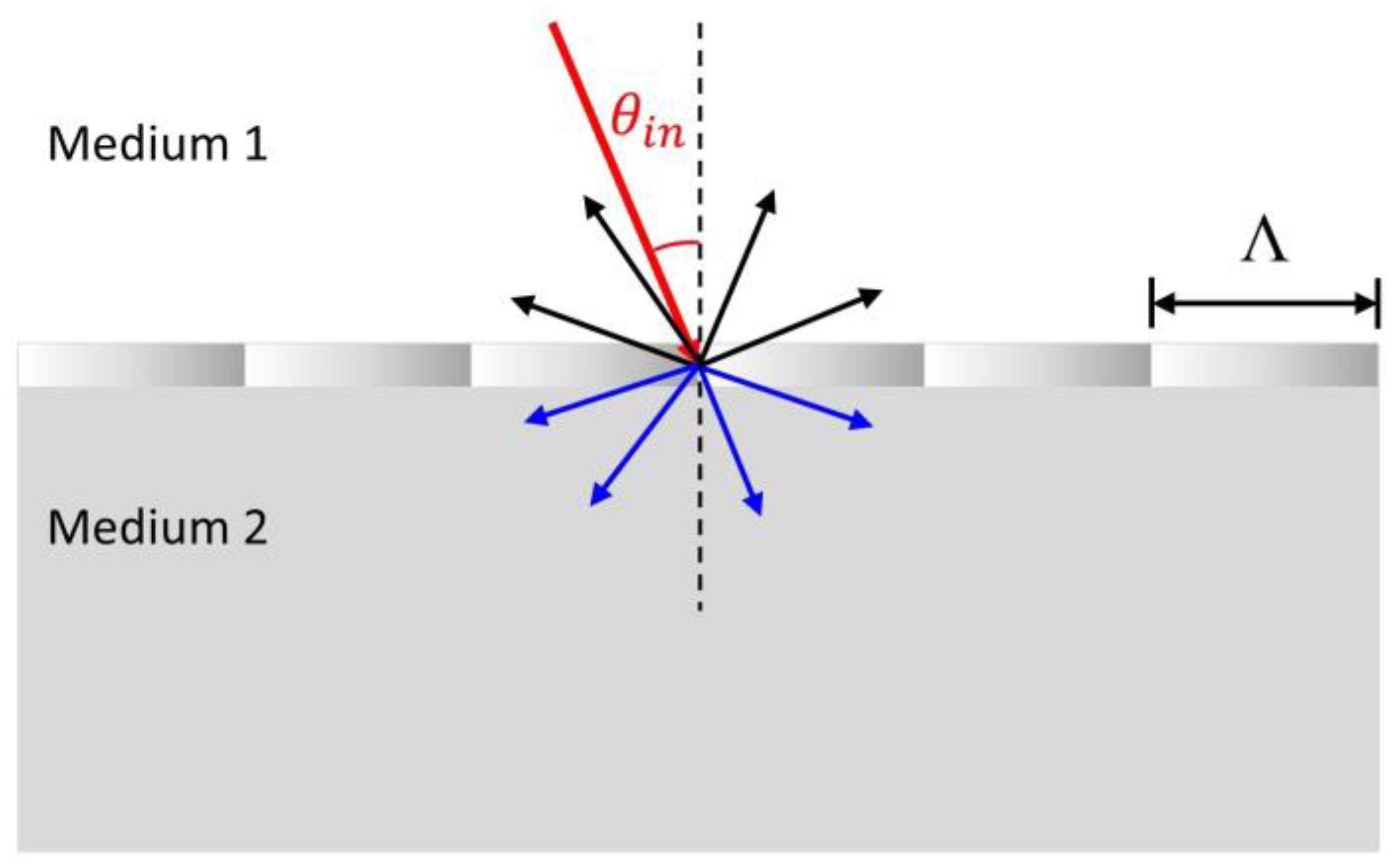
Figure 1 depicts the schematic of a one-dimensional (1D) grating. Generally, for a thin grating (Raman-Nath regime) [39], an incident beam can result in multiple diffracted beams, in both backward (reflection) and forward (transmission) directions. The diffraction angles are determined by the following grating equation [40]:
where n(1,2) is the refractive index in medium 1 or 2, θm,(1,2) is the angle of m-th diffraction order in medium 1 or 2, θin is the incident angle, Λ is the grating period, and λ0 is the wavelength in vacuum.
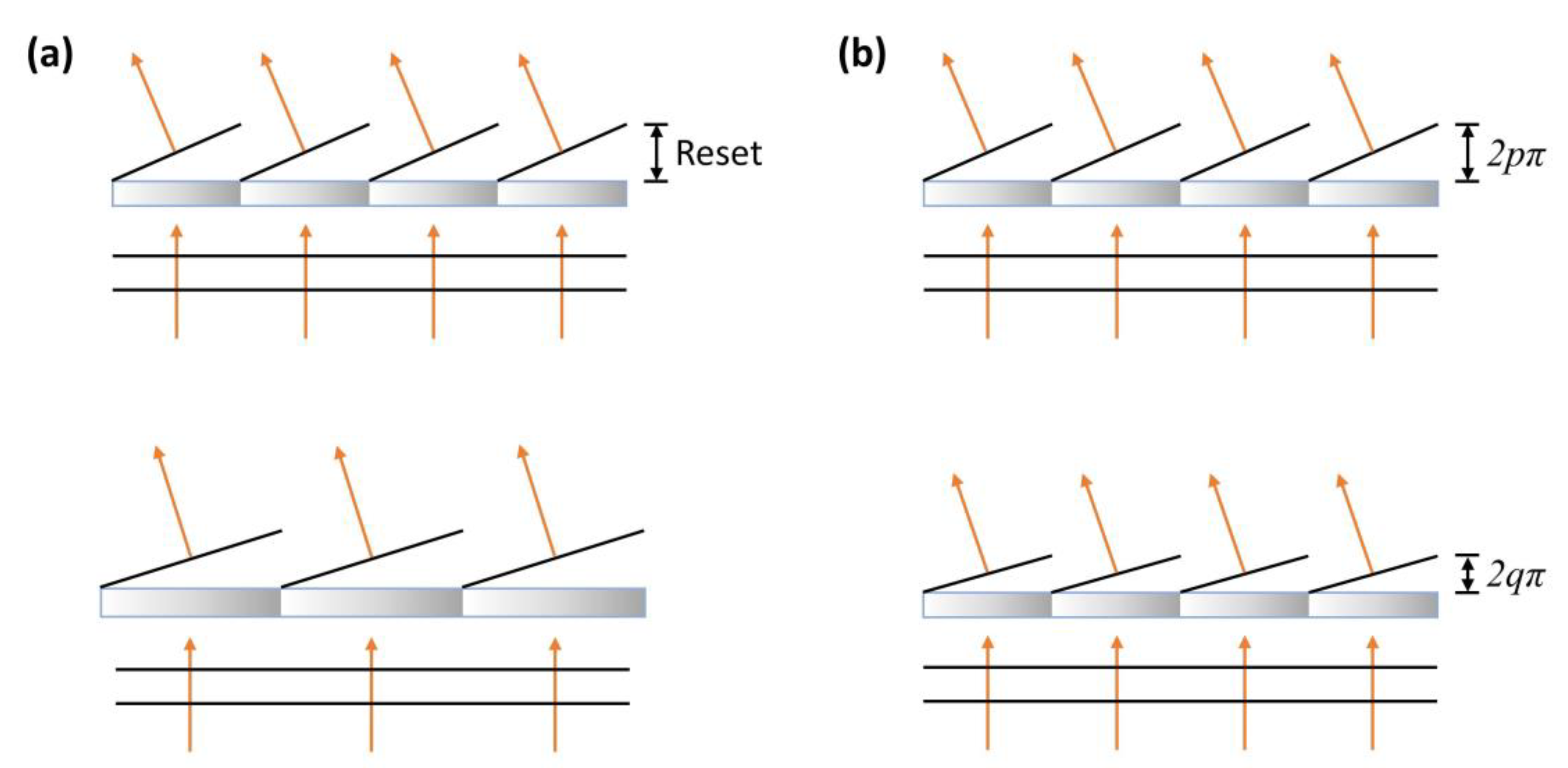
A desirable feature of the blazed grating is that a designed diffraction order can achieve maximum efficiency. In particular, the phase profile of a plane-wave passing through a blazed grating will become sawtooth-like. As depicted in Figure 2, there is a phase reset after each grating period. To reach maximum efficiency, for a given order m, the maximum phase difference within one period (or phase reset value) needs to be 2mπ. Based on the highly selective diffraction of blazed gratings, two beam steering approaches can be realized. The first is to vary the grating period: As shown in Figure 2a, as long as it stays at the blaze condition, maximum diffraction efficiency can be maintained at the m-th order (normally, 1st order) while θm changes according to the grating period. In this approach, the steering angle can be tuned continuously, in principle. The second approach is through varying the phase reset value—for example, from p-th order to q-th order (or other orders)—as Figure 2b shows. As the grating period is fixed, the steering angle can only achieve discrete values, as described by Equation (1).
2.2. Bragg Gratings
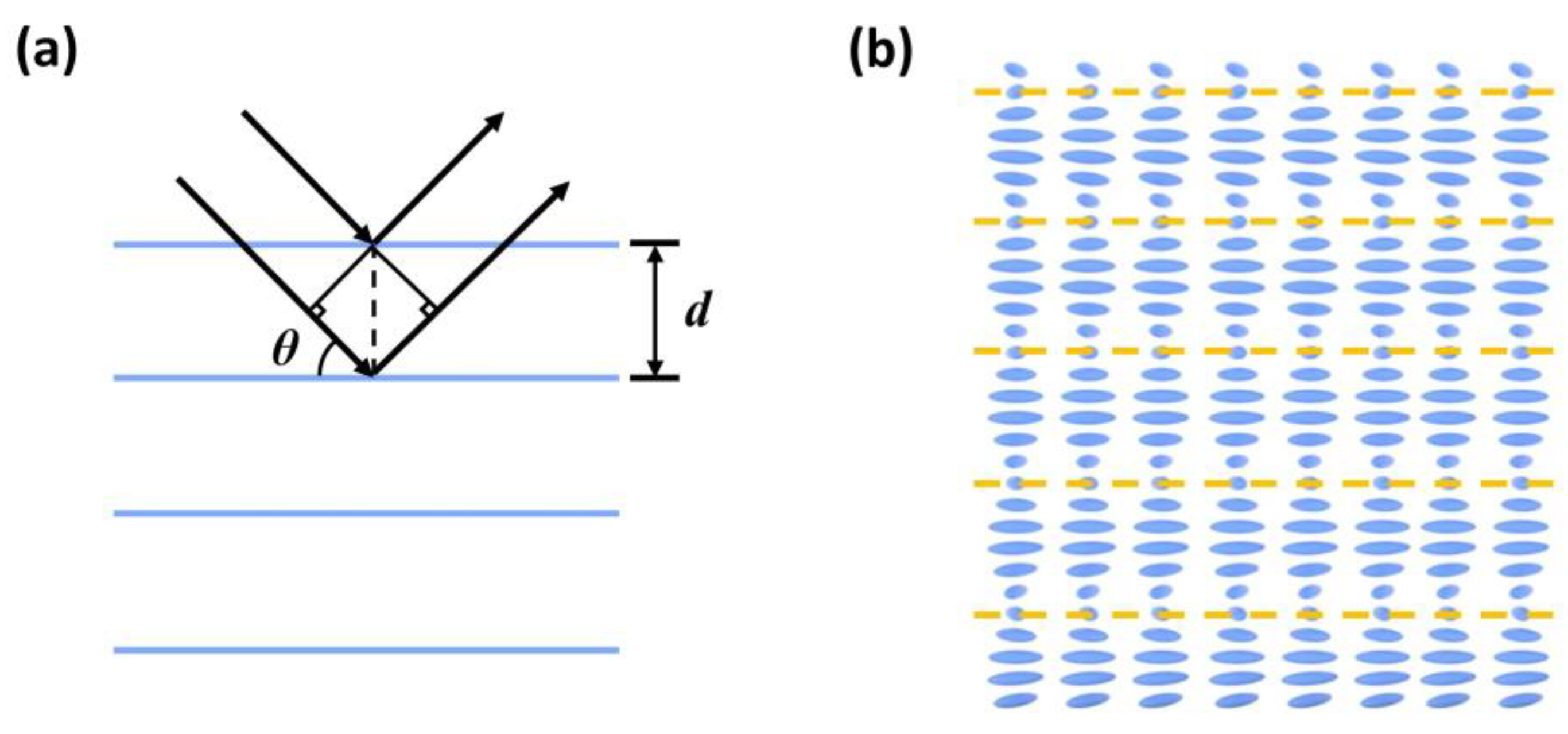
The second category is volume grating. Unlike the above-mentioned blazed grating, volume gratings are based on thick gratings (Bragg regime). Figure 3a depicts a 1D Bragg grating, where the blue lines are the periodic planes. In such a thick grating, the establishment of high-efficiency diffraction needs several periods, and the reflections from each plane add up coherently. A distinct feature of these gratings is a high sensitivity to incident wavelengths and angles. The Bragg condition can be described as:
where d is the period, θ is the angle between planes and incident beams, and λ is the wavelength in the medium. A well-known example of LC Bragg gratings is cholesteric liquid crystal (CLC), as schematically illustrated in Figure 3b. A CLC structure can be formed by doping some chiral compounds into a rod-like nematic host. In a CLC phase, the LC directors rotate continuously along the stacking direction, and a helical structure perpendicular to the layer planes (orange dashed lines) exists. To establish Bragg reflection, usually about 10 pitches are needed [29]. The reflection is also strongly dependent on the incident angle and wavelength. By dynamically tuning the pitch length, the angle, as well as wavelength dependency, changes accordingly [41]. This is the principle employed for volume grating beam steering: By changing the period, within the bandwidth, the diffraction angle for a given wavelength varies. Another distinct feature is that a thick grating can steer incident light at a large angle with high efficiency, while a thin grating can hardly achieve that [42].
2.3. Prism-Type Beam Steering
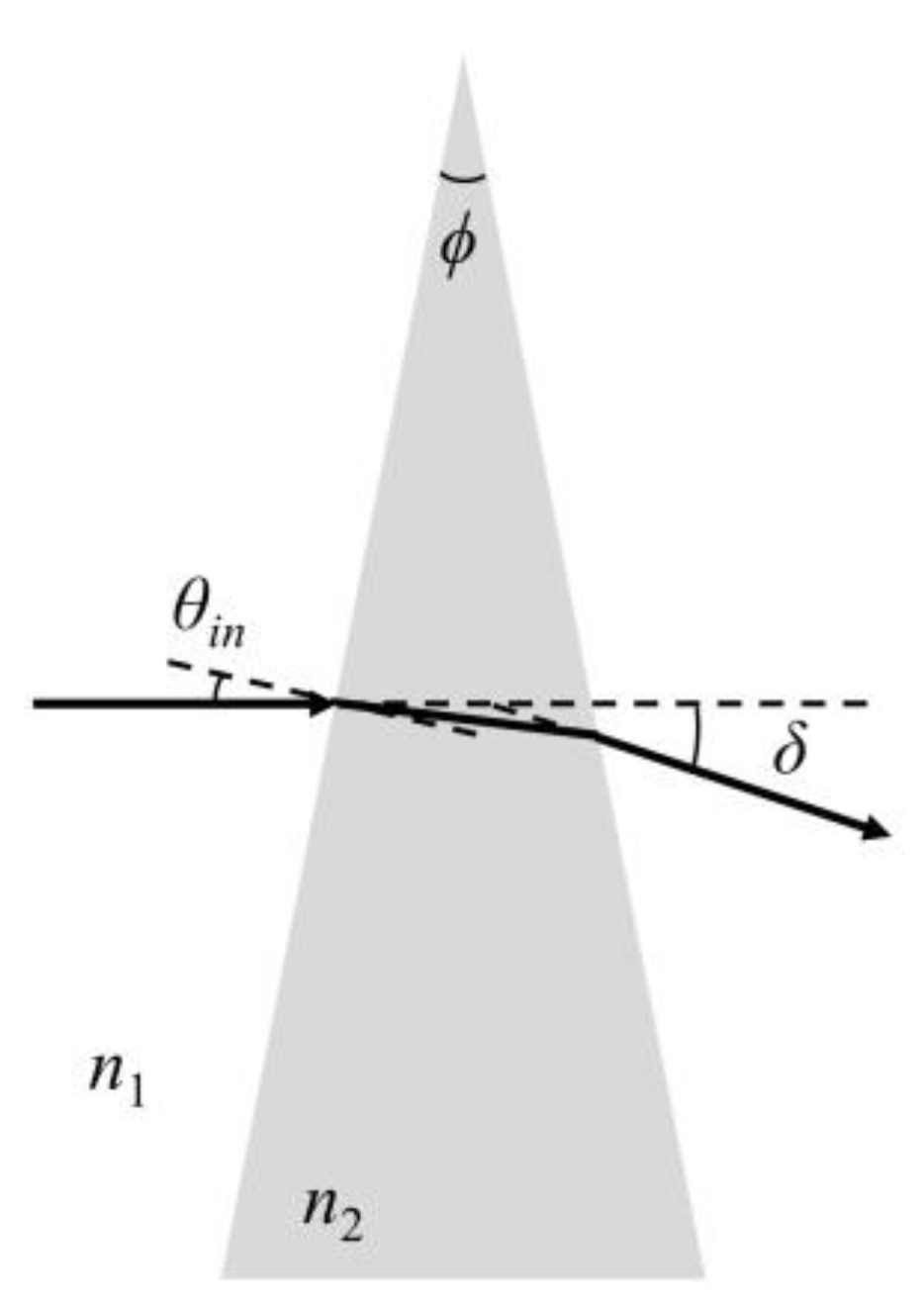
The third mechanism is prismatic beam steering. Differing from the above-mentioned blazed and volume gratings, prismatic beam steering is based on refraction rather than diffraction. As shown in Figure 4, when a light beam passes through a prism, the refraction at both interfaces leads to a deviated outgoing beam. Through a geometric optics calculation, the deviation angle δ can be expressed as:
where ϕ denotes the prism angle, n1 is the refractive index of background medium, and n2 is the refractive index of the prism. When the prism angle and the incident angle are small, Equation 3 can be simplified to:
For such a thin prism, the angular deviation is insensitive to the angle of incidence (θin) over a decent range, but it depends on the refractive indices of both media (n1 and n2) and the prism angle (φ). By this principle, we can tune the deviation angle by changing one of the refractive indices. However, traditional LC prisms can only vary in deviation angle over a small range, due to limited interaction lengths [43]. As will be discussed in Section 3.4, by increasing the interaction length, it is possible to obtain a large deviation angle (even up to 270°) through this mechanism.
3. Liquid Crystal Beam Steering Devices
In Section 2, we discussed the basic operation mechanisms of LC beam steering devices. In this section, we focus on six device configurations, including optical phased arrays, compound blazed gratings, resistive electrodes, LC-cladding waveguides, Pancharatnam–Berry phase gratings, and volume gratings. For each device, we will discuss its merits and demerits, and describe to which mechanism it belongs.
3.1. Optical Phased Arrays
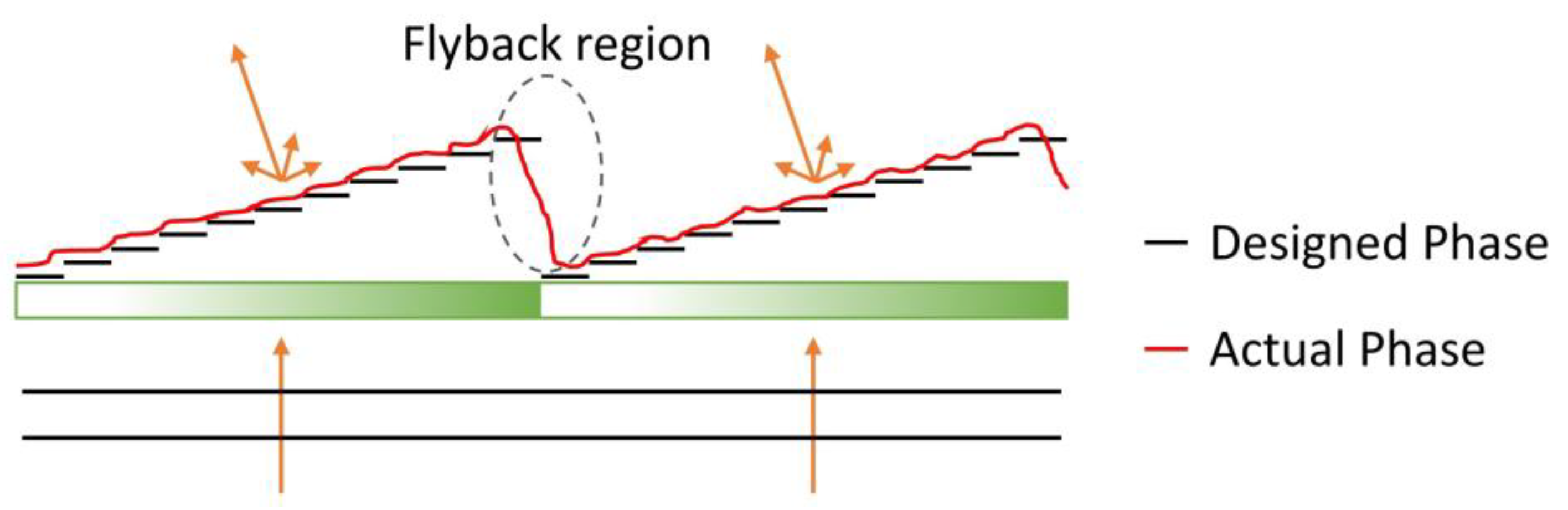
The LC-based OPA is a relatively mature beam steering technology, where homogeneous alignment with positive dielectric anisotropy (Δε) LC materials or vertical alignment with negative Δε LC materials can be considered. However, homogeneous alignment with a positive Δε LC is preferred, as negative Δε LC materials usually show a higher viscosity and lower |Δε|, leading to a slower response time and higher operation voltage [44]. These conventional OPAs intrinsically work only for one linear polarization and some design considerations have already been thoroughly discussed in several papers [28,33,45]. The mechanism of this type is a variable-period blazed grating (Figure 2a) with a 2π phase reset (only the 1st order is applied). Currently, the main issue for OPAs (of both homogeneous and vertical alignments) is the fringing field effect, which occurs when different voltages are applied on adjacent pixels, resulting in an unwanted phase distortion to the LC directors. This distortion becomes more noticeable as the pixel pitch to cell gap ratio gets smaller. For instance, for a reflection-type OPA—such as LC-on-Silicon (LCoS)—the cell gap can be reduced to one-half of the transmission type while keeping the same phase change. Under such conditions, the fringing field effect will be smaller. The most severe effect appears at the phase reset region, which is often referred to as the flyback region [46], as depicted in Figure 5. The efficiency drop due to the flyback region can be estimated by [33]:
where η is the efficiency, w is the width of the flyback region, and Λ is the width between phase resets. From Equation 5, for a fixed w, efficiency drops drastically with decreasing period; that is, the OPA can only maintain a relatively high efficiency within a small steering angle range (e.g., at ±5°, the optical efficiency has already dropped to approximately 60%). The beneficial part is that, within this small tuning range, the steering is quasi-continuous. OPA works well in the visible and near-infrared spectral regions. However, to extend its usable range to mid-wave infrared (MWIR), a thicker LC layer is needed in order to accumulate a 2π phase modulo, which will lead to a slow response time. To address this issue, we propose an improved LC mixture; detailed results will be discussed in Section 4.1.
3.2. Compound Blazed Gratings
The compound blazed grating was first demonstrated almost two decades ago [47]. Utilizing electron beam lithography, a PMMA (Poly(methyl methacrylate)) blazed grating can be fabricated on top of an indium tin oxide (ITO)-glass substrate. The final device is accomplished through the assembly of a homogeneously-aligned LC cell and the diffraction appears only for one linear polarization parallel to the LC alignment direction. The working mechanism is the variable diffraction order blazed grating (Figure 2b), where the devices are switchable between the 1st (voltage-off) and 0th (voltage-on) orders. By matching the refractive index of the PMMA with the ordinary refractive index of the employed LC, unwanted diffractions in the voltage-on state can be eliminated. In [47], four devices with different grating periods were fabricated and stacked together to realize multi-angle beam steering. The efficiencies of steering a beam to 13.5° (largest angle) and 0° were approximately 30% and 58%, respectively. Beside the Fresnel loss by stacking multiple devices, the device efficiency mainly suffered from the flyback effect, caused by the imperfect PMMA blazed grating fabrication and distorted LC directors. Although current e-beam lithography systems can achieve better control, the fabrication method itself is not a low-cost choice.
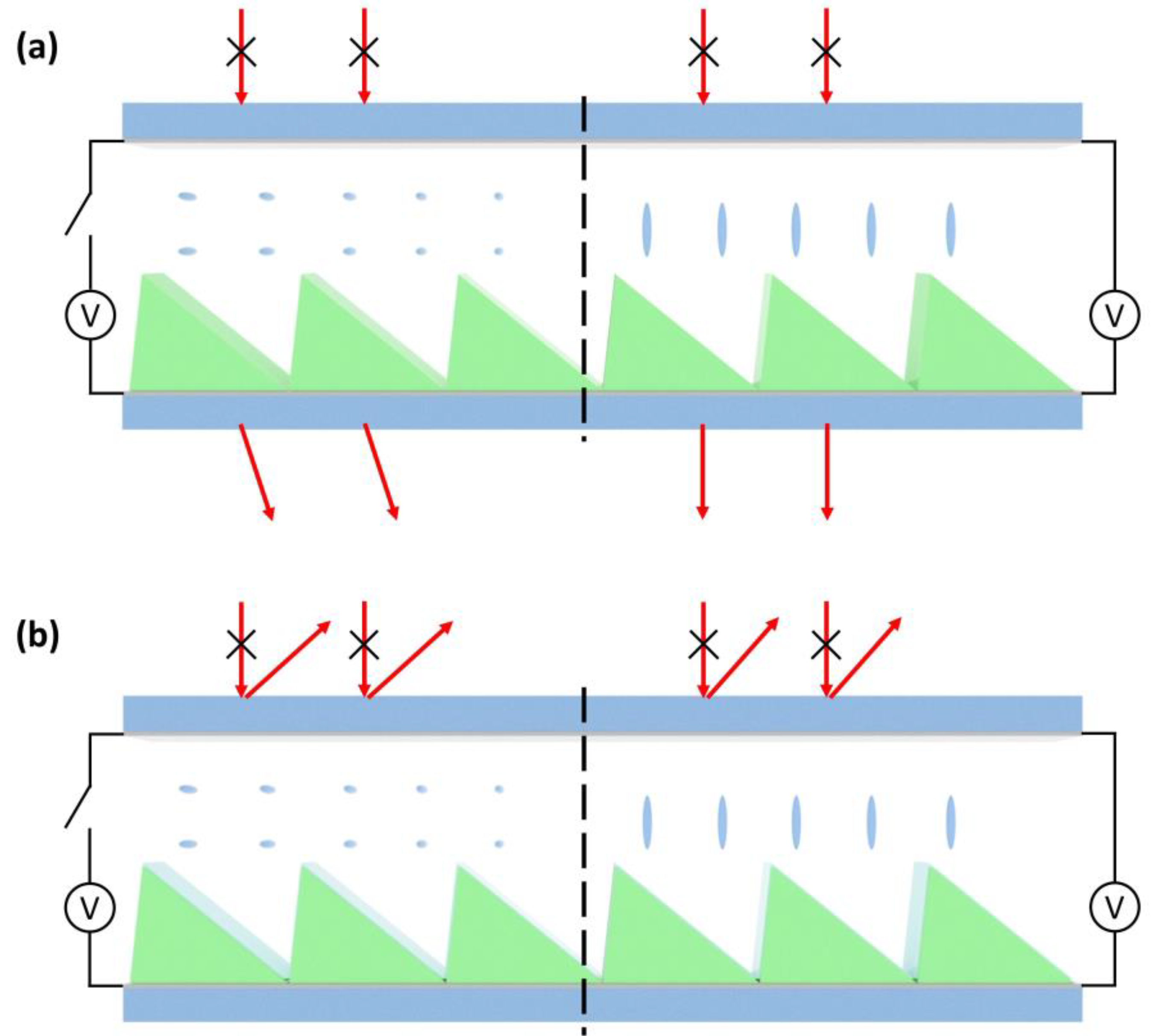
To lower the cost of the sophisticated fabrication process, we could consider the imprinting method, which has exhibited good reliability. The fabricated PMMA blazed gratings are much larger, such that applying the same mechanism (variable diffraction order blazed grating), the imprinted blazed gratings can switch among higher orders. Two configurations have been proposed; namely, the transmissive [48] and reflective [49] modes, as shown in Figure 6a,b, respectively. In transmissive mode, the voltage-off state provides the highest steering angle. As the voltage increases, the steering angle starts to decrease (for example, from 4th order to 3rd order), approaching even negative orders (−1st), and jumps back to the 0th order. The reason it reaches negative orders is that the dielectric constants of the LC materials (E7, in this case) and PMMA are different. The voltage shielding effect in the thin PMMA region is smaller than that in the thick region. As a result, at a given voltage, the LC directors in the thin PMMA regions are already tilted up, but they are not fully reoriented in the thick PMMA regions. This is an important aspect to take into consideration when designing the compound structures. On the other hand, a reflective mode can be generated by simply depositing a thin reflective film (Ag, Al, or so on) on top of the PMMA. It is worth mentioning that, in the reflective mode, even in the state where the LCs are all tilted up, the light beam will be directed to a large diffraction order, possibly achieving large angles (e.g., 30°), rather than the 0th order, due to the optical path difference introduced by reflection. For both configurations, the steering angle is discrete and the steering range is limited to several degrees. The steering efficiency can approach 100%, in theory, if an ideal blazed phase profile is satisfied. However, experimentally, the efficiency is only 30–50%; this is mainly due to the flyback effect, but other factors, such as Fresnel reflections and disordered LC directors, also contribute to the efficiency loss.
3.3. Resistive Electrodes
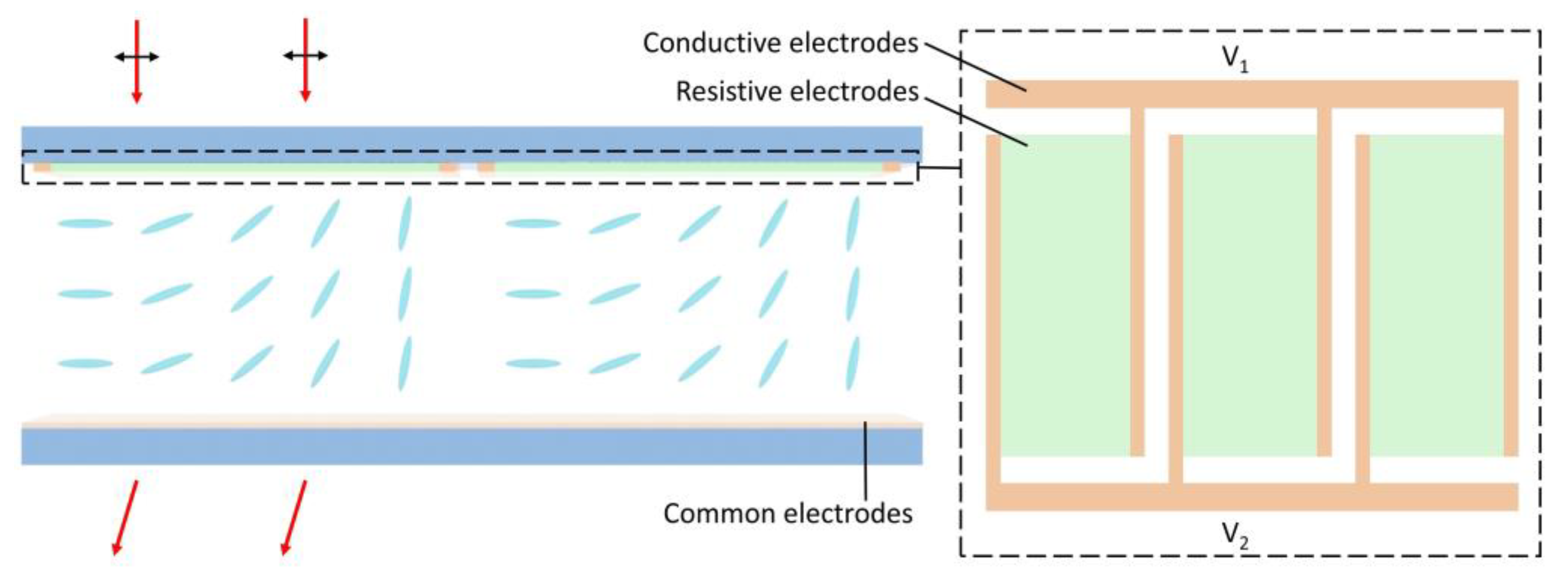
Beam steering using resistive electrodes can be realized by creating a gradient voltage drop in a homogeneous or vertical alignment LC cell. Figure 7 depicts the device configuration of such a LC cell, with a resistive electrode on the top substrate. Overall, there are three types of electrode with different functions. The planar common electrodes at the bottom substrate are grounded, while the conductive electrodes create a voltage difference across the resistive electrodes (usually a resistive film). The working mechanism is the variable diffraction order blazed grating and the maximum diffraction angle depends on the electrode dimensions and LC layer thickness. A beam steering device using metal for conductive electrodes and a metal-oxide for resistive electrodes was proposed and fabricated about two decades ago [50]. A 76% diffraction efficiency was obtained within the maximum deflection range of ±0.34°. More recently, employing patterned ITO for the conductive electrodes and poly(3, 4-ethylenedioxythiophene):polystyrene sulfonate (PEDOT:PSS) for the resistive electrodes, a maximum steering angle of 4.8° was achieved, where the steering angle could be varied among many diffraction orders [51]. However, due to the thick cell gap (about 30 μm), the response time was slow (several seconds); further, the efficiency was not very high, as the steered beam spots were gloomy (the exact efficiency was not reported). This approach mainly suffered from the flyback region effect and a non-ideal phase gradient, along with other concerns with regards to increased power consumption resulting from the resistive electrodes. Nevertheless, to improve the phase gradient, a device optimization method has been developed [52].
In fact, to achieve a phase gradient without compound structures, the resistive electrode approach is not the only option. For instance, by step-by-step polymerization of reactive mesogens in a homogeneous alignment cell, phase-gradient gratings can be generated where the phase profile is controlled by applying different voltages [53,54]. Nonetheless, the fabrication process is complicated, especially for small steps, and defects could form during polymerization, which will ultimately limit the performance of the device.
3.4. LC-Cladding Waveguides
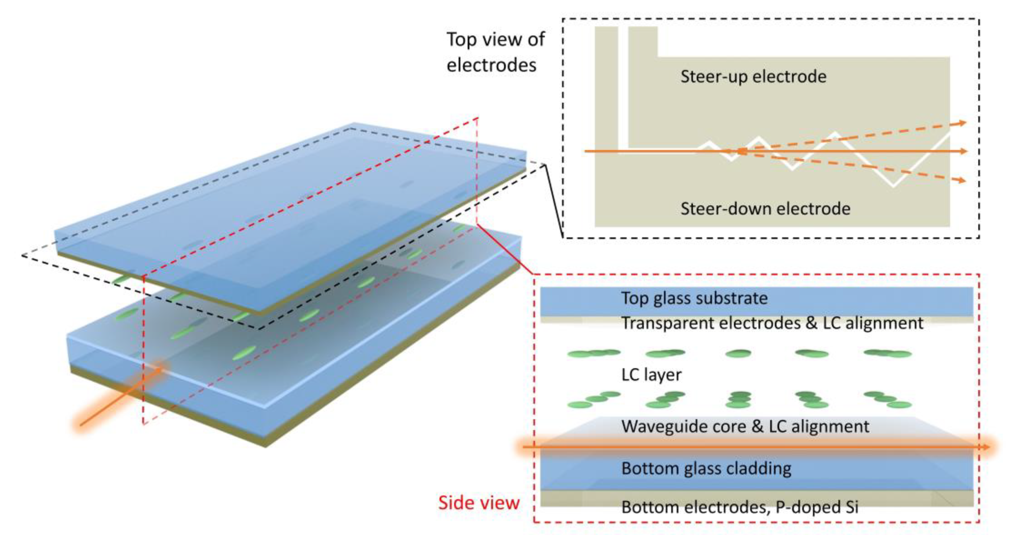
As mentioned in Section 2, LC prisms can only achieve relatively small steering angles, due to the limitations in LC refractive index change and prism geometry [43]. However, the interaction length can be dramatically increased by guiding light using a waveguide, as Vescent Photonics demonstrated about a decade ago [55]. The main feature of in-plane steering is plotted in Figure 8. This special waveguide consists of LC cladding, a Si3N4 core, and glass cladding. Beam steering is achieved by manipulating the evanescent wave in the LC cladding region. The homogeneous LC alignment is along the light propagation direction, and the top zigzag-shaped electrodes are divided into two parts. If a voltage is applied on the steer-up electrode while the other electrodes are grounded, the transverse-magnetic (TM) mode will experience multiple prisms, where the region under the steer-up electrode has a higher refractive index. According to Equations 3 and 4, the light will be steered up. By controlling the applied voltage, the refractive index contrast of the prisms can be managed. Therefore, this configuration has a very high angular resolution. As the LC prisms only interact with evanescent waves, only the LC directors near the interface are involved. Thus, the response time is in sub-millisecond range. By special design of the electrodes, a very large steering angle (up to 270°) has been demonstrated. This device can also steer light in the vertical dimension with a smaller range (for example, from 0° to 15°), achieved by adding another set of electrodes and using the tunneling mode. The major losses are from the Fresnel loss upon refractions and some in-coupling and out-coupling losses. However, as demonstrated, a waveguide amplifier can compensate for the losses [56]. The aforementioned systems work for near-infrared and short-wave infrared. Some follow-up works have extended the beam steering device into the MWIR range [57] with optimized materials that minimize absorption losses.
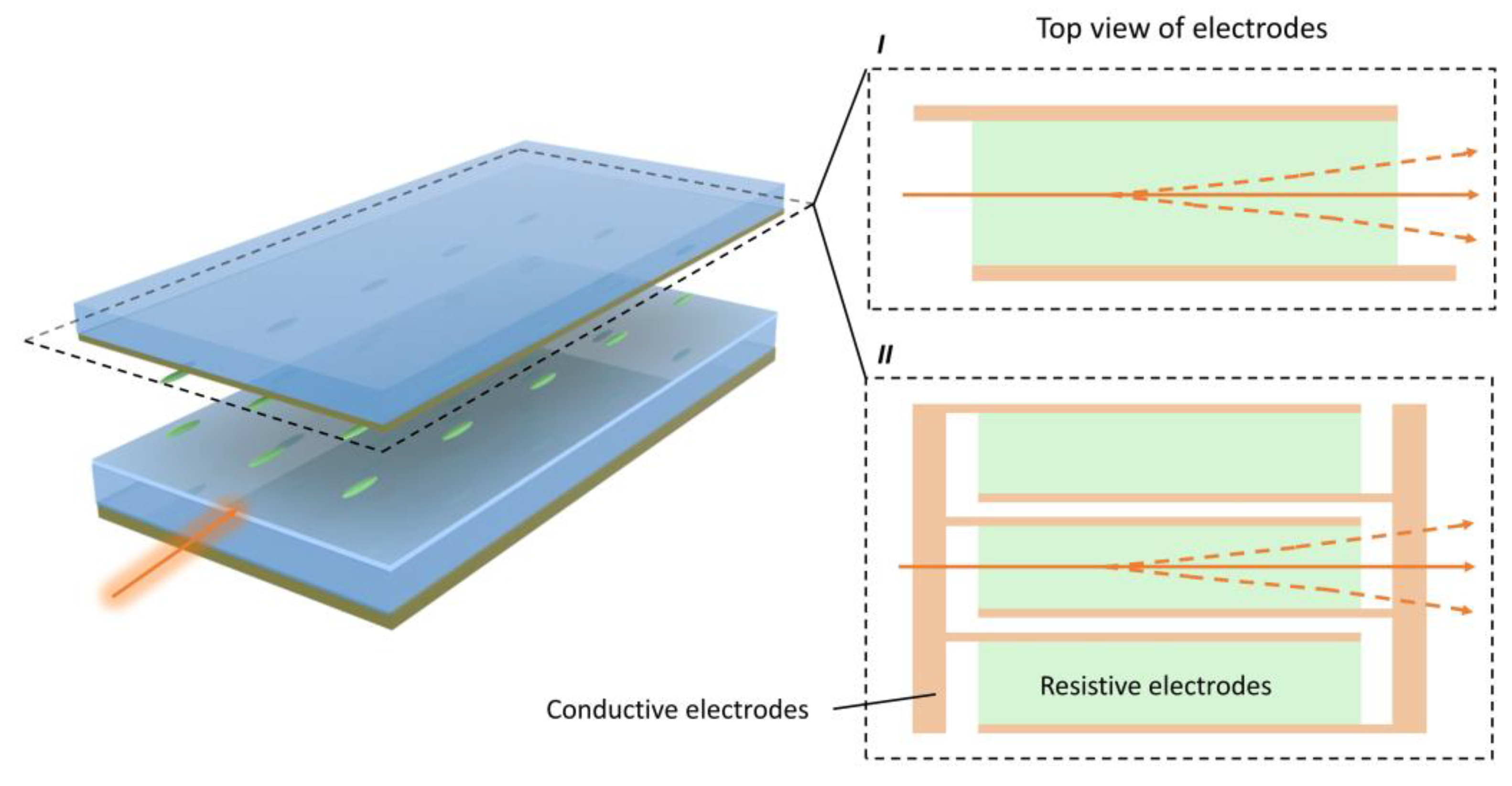
The LC-cladding waveguide is a general approach to extend the interaction length between LCs and light beams. As mentioned in Section 3.3, the resistive electrode approach has the same concern as the LC prisms in that, to increase the steering angle, a thick LC layer is needed. Here, we propose a beam steering concept that combines the LC-cladding waveguide with resistive electrodes. The device configuration is shown in Figure 9. In fact, the structure is similar to the previous waveguide beam steerer, except that the top electrodes are replaced by resistive electrodes. By creating a refractive index gradient and interacting with the evanescent waves, the LC thickness can be thin, and the accumulated phase gradient can be large, meaning that large-angle beam steering with fast response time is achievable. Ideally, a single resistive electrode (structure I in Figure 9) can provide continuous beam steering, as it is refractive. However, the width of the resistive electrode is closely related to the refractive index gradient and, thus, to the maximum steering angle (if the total length of the LC-cladding waveguide is fixed). For a compact design, a limited width of the resistive electrode is preferred, but the trade-off is that it can only work for small-sized beams. To enlarge the aperture size while maintaining the same maximum steering angle, a wider resistive electrode with a longer LC-cladding waveguide or an array of resistive electrodes can be applied (structure II in Figure 9). When designing the width of a single resistive electrode, we also need to consider the sheet resistance. Here, we perform finite-difference time-domain (FDTD) simulations to prove this concept. Due to the dimension limit in the simulations, we only test the performance of structure I. The parameters employed in our simulation are as listed below, unless otherwise stated; 1) The glass cladding material is SiO2; 2) the core material is Si3N4, with thickness of 500 nm and refractive index 2.0; 3) the LC alignment layer on the core is 20 nm thick, with a refractive index of 1.5; 4) the LC material has an ordinary refractive index of 1.5 and an extraordinary refractive index of 1.75; 5) the homogeneous alignment direction is parallel to the waveguide direction; 6) the width of the resistive electrodes is 40 μm for case 1 and 60 μm for case 2; 7) the waveguide length is 150 μm; and 8) the incident wavelength is λ = 1.55 μm and the incident beam is of fundamental TM mode.
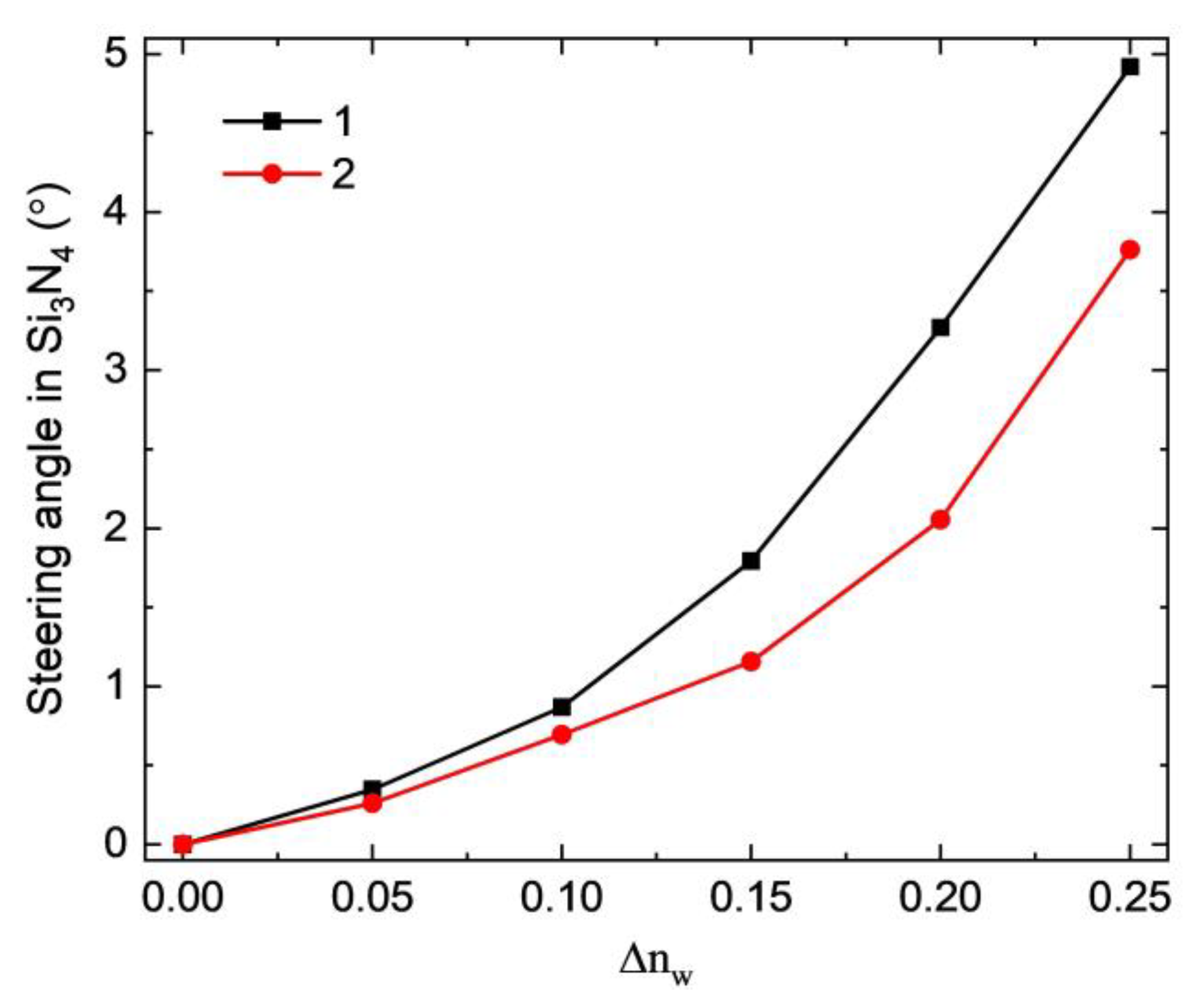
During the simulations, we analyzed two cases (1 and 2), with different refractive index gradients, by defining various refractive index differences (Δnw) between the two conductive electrodes and assuming that the refractive index changes linearly across the resistive electrode. In our case, the maximum bi-refringence was assumed to be Δn = 0.25. Although previous reports have demonstrated even larger Δn at 1.55 μm, the parasitic large visco-elastic constant will strongly increase the device response time and operating voltage [58,59]. Figure 10 depicts the simulated results (steering angle versus refractive index difference). The steering angle monotonically increases with the refractive index difference and the slope of increase is higher for a more compact dimension (case 1). For case 1 (40 μm resistive electrode width), a maximum steering angle of approximately 4.9° can be obtained within only 150 μm of propagation length. Compared to the prism-type waveguide, the resistive electrode-type waveguide could achieve the same steering angle at a shorter waveguiding distance, as the interaction between LC and light is continuous, while the interaction for the prism-type waveguide is discrete (only at the prism boundaries). However, the tradeoff is that, if structure II is utilized for a larger-size beam, the flyback region effect will again limit the diffraction efficiency. It should also be pointed out that the simulations are based on rather ideal situations, without an electrical response simulation of the LC directors. In the actual case, the refractive index change is not ideally linear and the LCs near the alignment layer should be less tilted due to the strong anchoring effect, which results in somewhat lower steering angles and efficiency. However, the refractive index change across the resistive electrode can be further optimized and the surface anchoring of LC directors can be effectively simulated by increasing the alignment layer thickness.
3.5. Pancharatnam-Berry Phase Deflecctors
With intrinsic polarization sensitivity and high diffraction efficiency, Pancharatnam-Berry deflectors (PBDs) [60,61], made of liquid crystals or liquid crystal polymers, are another promising candidate for non-mechanical beam steering. Unlike the traditional dynamic phase produced through optical path difference, the Pancharatnam-Berry (PB) phase corresponds to the phase shift introduced by other light-wave parameters, such as polarization transformation [62,63]. As a special case of PB optical elements [64,65,66], PBDs can be established by patterning half-wave plates with an in-plane linearly rotating optical axis, as depicted in Figure 11a. Their working mechanism can be simply explained by the Jones matrix:
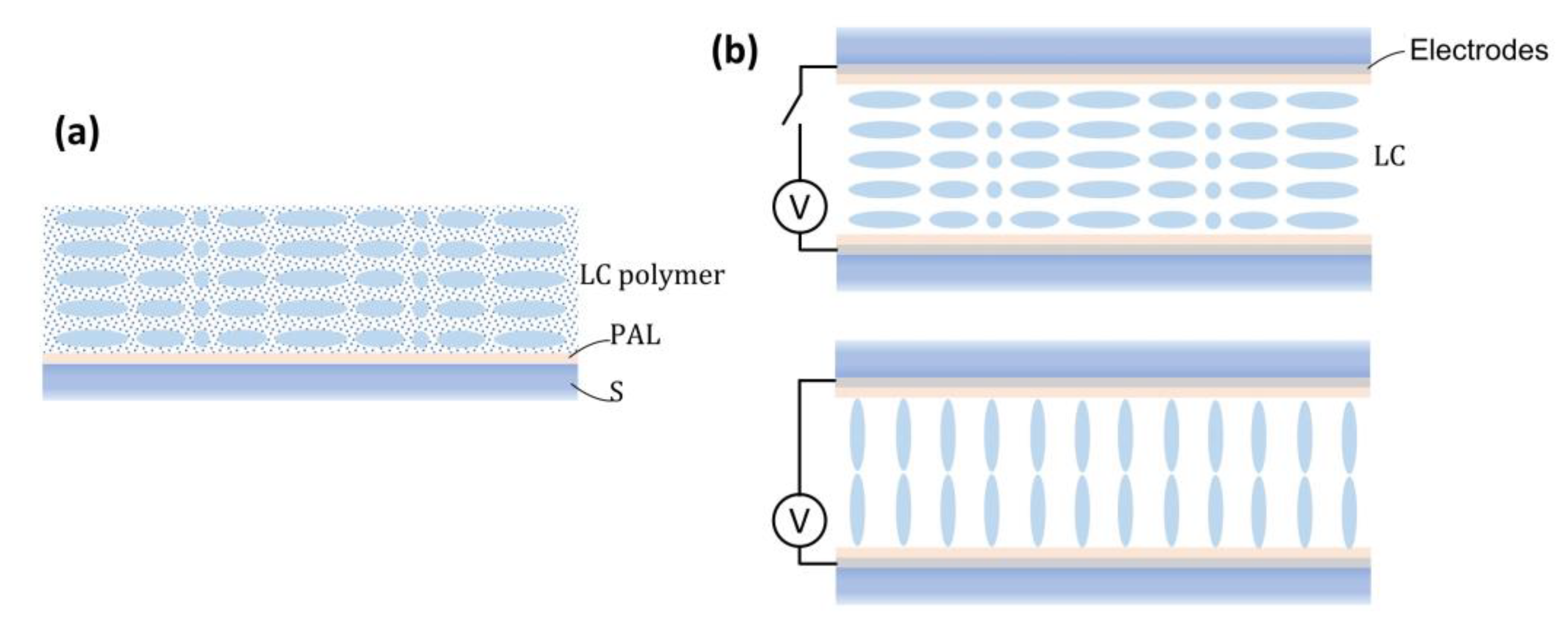
where R is the rotation matrix, φ is the optical axis orientation angle, W(π) is the half-wave retardation matrix, and J± are the Jones vectors of right-handed circularly polarized (RCP) or left-handed circularly polarized input light (LCP). With a linearly-rotating optical axis φ = πx/p, where p is the grating period, the PBD can deflect circularly polarized normal incident light into the first order with near 100% diffraction efficiency, in theory (within paraxial approximation), and flip the handedness of the light. Nonetheless, there are some limitations. The diffraction efficiency can reach 100% only within a relatively small angle, depending on the bi-refringence of the employed LC material (e.g., approximately 15⁰ with Δn about 0.2) [64]. Another study has demonstrated that the LCs cannot follow periodic alignment patterns well when the cell gap is less than a single period, where the LC directors rotate 180⁰ in the plane [67]. To fabricate PBDs, polarization holography [68,69] and photo-alignment methods [70] are usually applied to transfer the linearly rotating polarization pattern to the LC director orientation. In terms of the driving method, PBDs can be categorized into two types: Passive and active. Passive PBDs are generally prepared by coating a reactive mesogen layer onto an aligned surface (Figure 11a), while active PBDs are fabricated by filling LC into a cell with transparent electrodes and a patterned photo-alignment layer (Figure 11b). If the applied voltage is high enough (usually <15 V), the LC directors are re-oriented along the electric field directions, so that the deflection effect of the PBD vanishes.
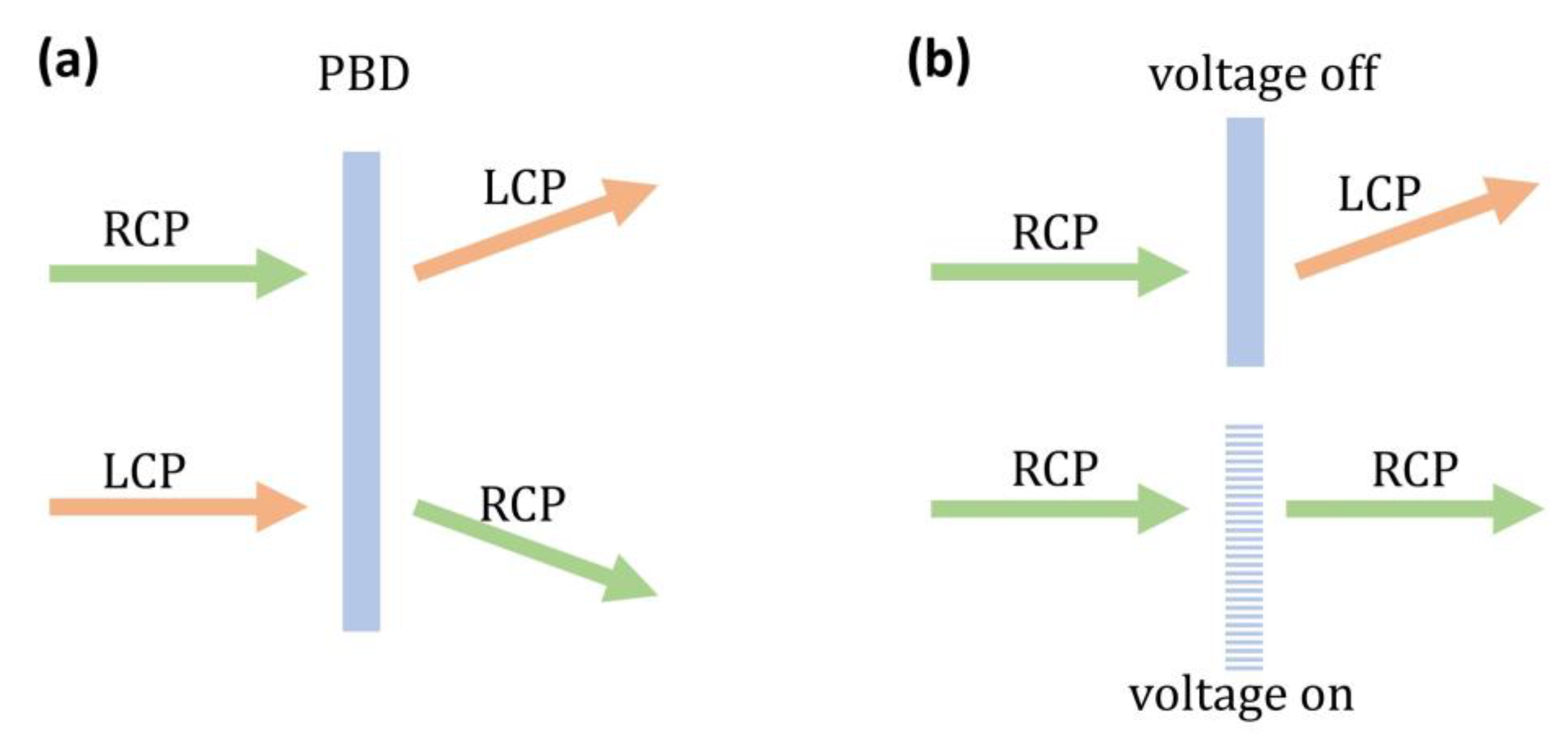
In principle, two beam steering schemes can be realized through PBDs. Firstly, because the diffraction is highly polarization-selective, the deflection angle of the PBD can be switched by controlling the input polarization state, such that the output beam can switch between +1 and −1 diffraction orders, as depicted in Figure 12a. In this scheme, a polarization rotator (e.g., a 90° twisted-nematic cell) and a quarter-wave plate are placed in front of the PBD to dynamically select the input polarization. Secondly, for active PBDs made of liquid crystals, the input beam can be switched between the zeroth and first diffraction orders, simply by applying a voltage to the PBD, as illustrated in Figure 12b. The working principles are that of the variable diffraction order blazed grating and the most intriguing property is that these devices are free from the flyback issue. To obtain multiple steering angles, the simplest way is to stack multiple PBDs together [71]. With N-cascaded PBDs working as illustrated in Figure 12a,b, beam steering with 2N discrete angles can be realized. Apart from the binary switch through the aforementioned two approaches, a ternary switch is also possible if we cascade N PBDs that are both switchable and with polarization rotators and quarter-wave plates (combining both approaches) [72]; then, 3N discrete angles can be generated. Furthermore, thanks to the diversity of LC and LC polymer materials, PBD-based beam steering devices have been demonstrated in the visible [73], near infrared [72], and MWIR [74] regions. More recently, multi-twist structures [75] and twisted-nematic diffractive waveplates [76,77] have been proposed and were demonstrated to show a broader bandwidth (from visible to infrared), in comparison with traditional PBDs. Furthermore, 2D PBDs [78,79,80,81], which can diffract beams into multiple directions, have recently emerged. In addition to varying the diffraction orders, there have been other proposals to change the period by using a sophisticated design of the alignment layer and electrodes [82]. However, the feasibility of this approach remains to be proven.
3.6. LC Volume Gratings
Volume gratings (Bragg regime) have the ability to split and diffract beams into different directions. With meticulous design, volume gratings exhibit several distinctive features: Strong polarization selectivity, high diffraction efficiency, and large deflection angles. As a typical volume grating, the early-developed holographic polymer-dispersed LC (HPDLC) is a candidate for beam steering applications with switching ability and polarization dependency [83,84]. By stacking multiple holographic volume gratings together, discrete steering angles can be realized. However, fabrication challenges exist for high quality HPDLC-based holographic gratings, due to the induced inhomogeneity during the diffusion process, resulting in optical imperfections in the structure [84].
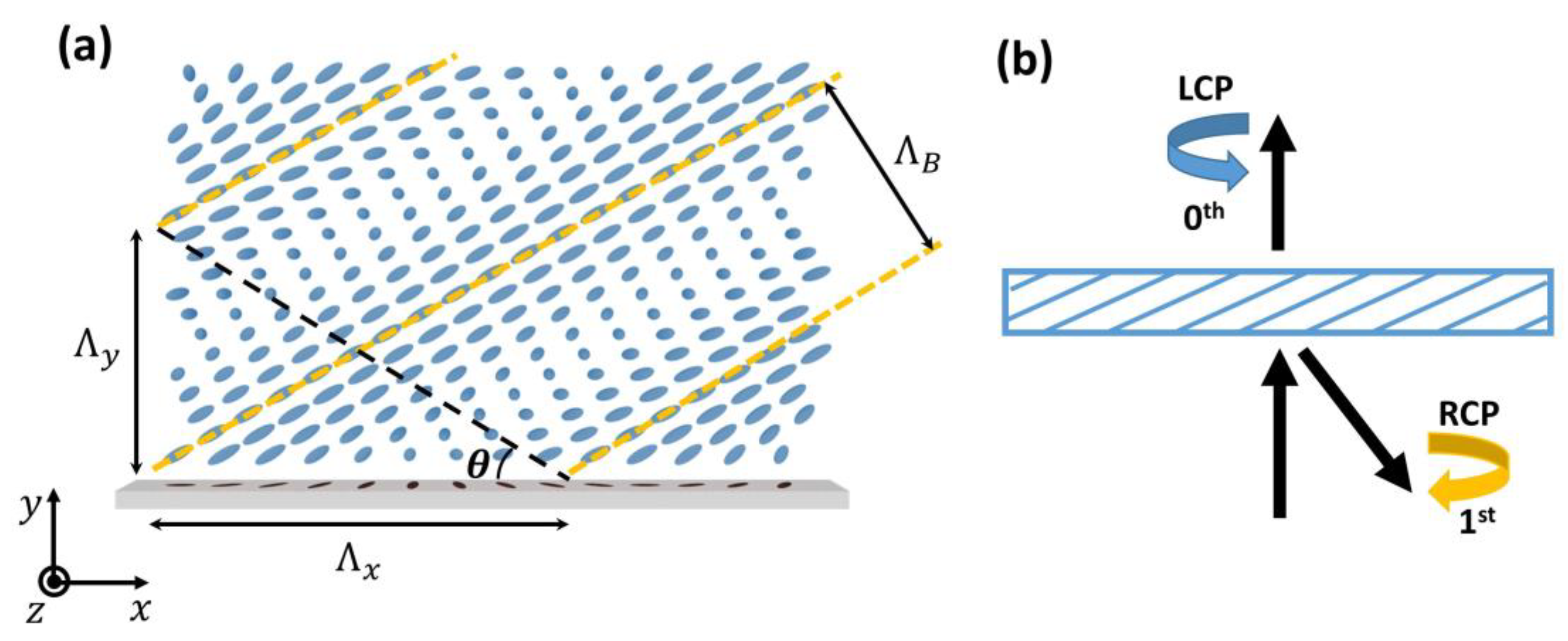
Besides HPDLC, the recently-developed LC polarization volume gratings (PVGs) are more attractive, due to their near-100% diffraction efficiency [42,85,86,87,88,89,90]. Figure 13a illustrates the LC director distribution of a reflective PVG [85]. The Bragg period and periods along the x and y directions are ΛB, Λx, and Λy, respectively. This asymmetrically self-organized structure enables unique polarization selectivity, where only light with the same chirality as the helical twist will be diffracted. Figure 13b depicts the polarization states of the diffracted and transmitted beams for a typical reflective PVG. Here, we assume that the handedness of the PVG is right-handed along the incident direction. Therefore, such a PVG can diffract the RCP light to the first order and keep its polarization state. Meanwhile, the LCP light will pass through the PVG without changing its polarization state. The same working principles can be applied to transmissive PVGs, except that the diffracted light will flip its handedness [42]. For instance, if an RCP light is incident on a transmissive right-handed PVG, the outgoing light will be diffracted into the first order with polarization changed to LCP.
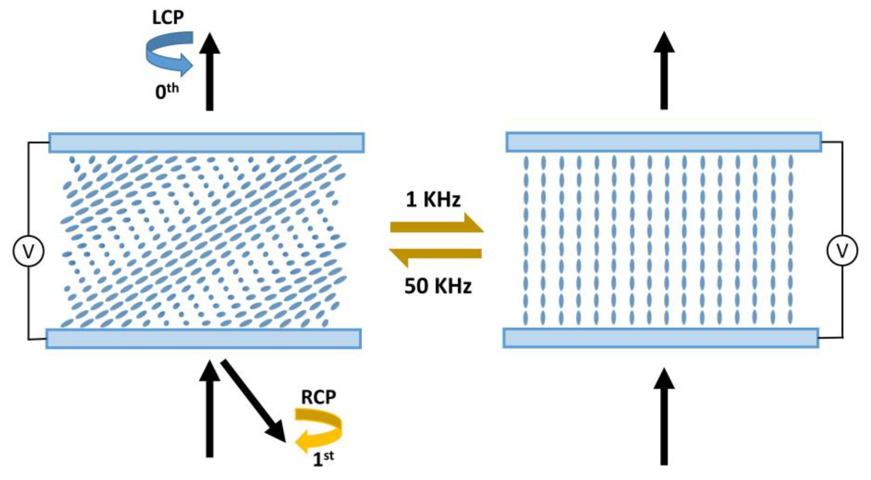
Compared to other LC-based devices (such as PBDs), PVGs possess a larger diffraction angle with high efficiency. With proper organization, the diffraction angle can reach 70° or even larger, while keeping diffraction efficiency over 90% for a single PVG. These unique advantages make PVG a promising candidate for beam steering applications. While PVGs can be applied as a passive beam steerer, with the help of the fast-switching polarization rotator mentioned in Section 3.5, active PVGs can also be achieved by assembling a cell with dual-frequency LC materials [91]. As manifested in Figure 14, after applying a voltage of 50 V (1 kHz), the LC directors are re-oriented to the homeotropic state, where the Bragg grating effect disappears. Switching the frequency of the applied voltage to 50 kHz can turn it back to the Bragg grating state.
As mentioned in Section 2, volume gratings possess stronger selectivity in wavelength and angle than thin gratings and this should be considered when targeting specific wavelengths. As a rule of thumb, the central wavelength of a PVG can be precisely designed by the modified Bragg condition:
where n is the average refractive index of the employed LC materials and θ is the slant angle, defined by tanθ = Λy/Λx. Typically, the bandwidth ranges from 30–50 nm, related to the Δn of the employed LC material. The field of view (angular response) for the central wavelength is around 20°. Fortunately, by applying multi-layer structures, both spectral and angular bandwidths can be dramatically increased while keeping a high diffraction efficiency [92].
4. Future Trends and Challenges
4.1. Fast Response Time for MWIR Beam Steering
As mentioned in Section 3.1, for LC-based beam steering devices (such as OPAs), homogeneous alignment with a positive Δε LC is preferred. The phase change (δ) of a homogeneous cell is governed by the cell gap (d), wavelength (λ), and bi-refringence (Δn), as:
On the other hand, the free relaxation time of a homogeneous LC cell is determined by [93]:
where γ1 is the rotational viscosity and K11 the elastic coefficient of the employed LC. In the visible region, a 2π phase change can be easily satisfied. However, as the wavelength increases into the MWIR or long-wave infrared (LWIR) region, as Δn decreases and then gradually saturates [94], a relatively thick LC layer is required, which dramatically increases the response time.
To improve response time while maintaining 2π phase modulation, polymer network liquid crystal (PNLC) has been proven to be an effective approach [58,95]. It consists of a LC host, a small amount of monomer (4–10 wt%), and a photo-initiator (<0.5 wt%) as a photo-polymerizable precursor. After the mixture is filled into a homogeneous LC cell and cured with UV light, a cross-linked polymer network with sub-micron domain size is formed. The polymer network provides strong anchoring energy, which helps to shorten the response time significantly. In this case, the free relaxation time can be estimated using Equation 9, except where d denotes the average domain size. Therefore, a smaller domain size is preferred to accelerate the relaxation. However, a major tradeoff is the increased operating voltage. In order to decrease the voltage, we can minimize the cell gap by employing a high Δn LC.
In addition to response time, LC absorption in the IR region, originating from vibrations of molecular bonds and functional groups, needs to be minimized [96]. To address this issue, we develop an improved eutectic mixture UCF-13, which consists of fluorinated or chlorinated terphenyl LC compounds [58,59,97]. Their chemical structures and compositions are listed in Table 1. The fluoro- (F) and chloro- (Cl) substitutions help shift the vibration absorption band to a longer wavelength and offers good UV stability. Additionally, the terphenyl core structure and terminal cyano (CN) group contribute to high Δn. Therefore, mixture UCF-13 offers low absorption loss, high Δn, and excellent UV stability, which make it a good PNLC candidate for achieving fast response times.
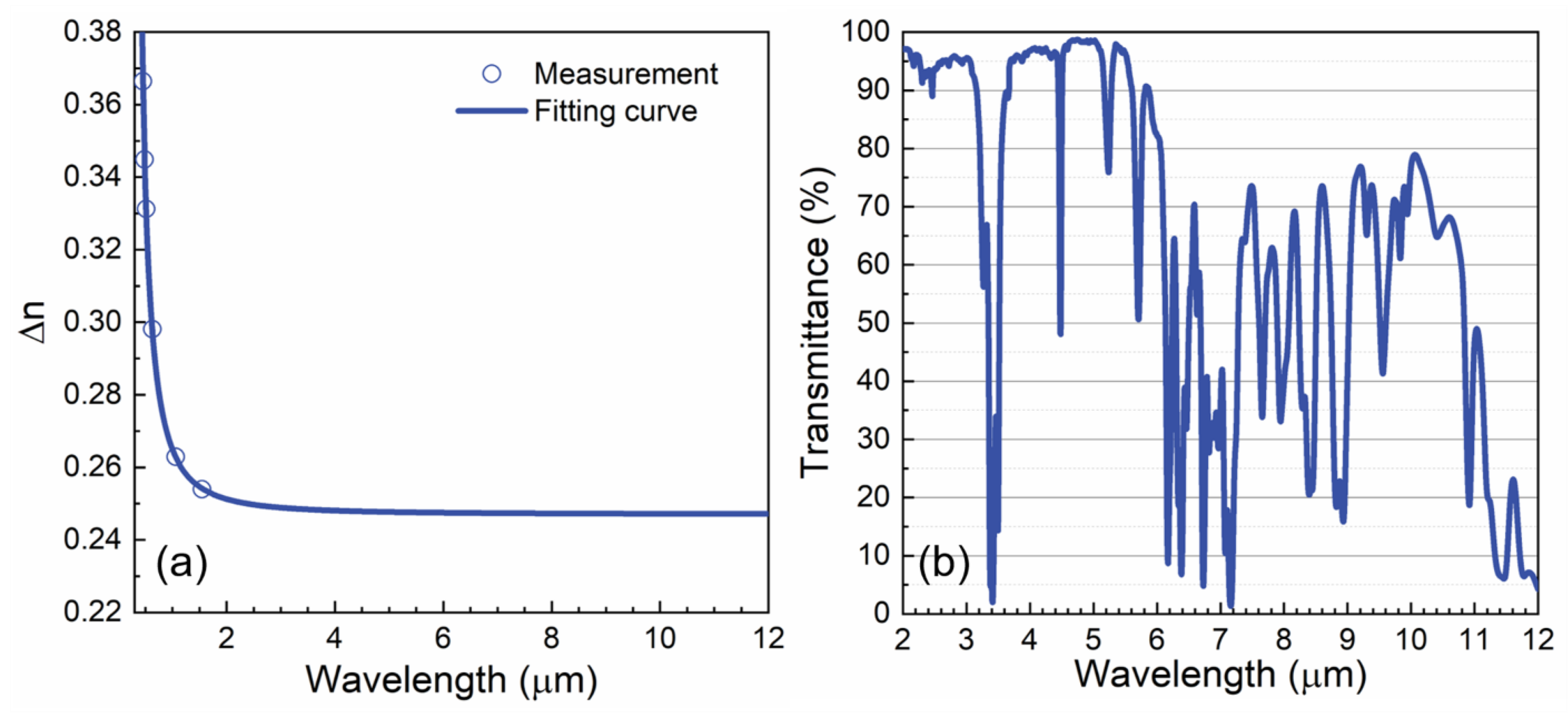
The wavelength dependent bi-refringence of UCF-13 was measured and the results are plotted in Figure 15a. According to the fitting results by the single-band bi-refringence dispersion equation [94], UCF-13 exhibits a relatively high Δn (0.249) in the MWIR and LWIR regions. Figure 15b depicts the transmittance of UCF-13 in a LC cell with d = 30 µm. In the MWIR region (3–5 µm), although a strong absorption peak occurs at λ = 4.48 µm (due to the CN vibration), its bandwidth is narrow and the baseline transmittance in the off-resonance region (3.8–5.1 µm) is over 96%.
Figure 16 shows the measured voltage-dependent phase change of our transmissive PNLC sample at λ = 4 μm and four specified temperatures. Although the reflective mode helps the reduce voltage by doubling the optical path length, the transmissive mode is usually preferred, due to its simpler optical system. Besides, the maximum voltage provided by a reflective driving backplane (such as LCoS) is only approximately 24 V [98], which is inadequate for our PNLC. In order to lower the operating voltage for transmissive PNLC, while keeping the response time at millisecond level, we intentionally increase the domain size by controlling the monomer (RM257) concentration at 4.1 wt% and curing temperature at 35 °C. As shown in Figure 16, at T = 25 °C, the voltage for achieving 2π phase change (V2π) is above 150 Vrms. If we increase the temperature to 40 °C or 60 °C, then V2π drops to 140 Vrms and 150 Vrms, respectively, which is achievable by driving the backplane for transmissive devices. As the temperature increases, Δn, Δε, and K11 decrease, but at different rates. Thus, 40°C seems to be a good compromise for our PNLC, from a low operation voltage viewpoint.
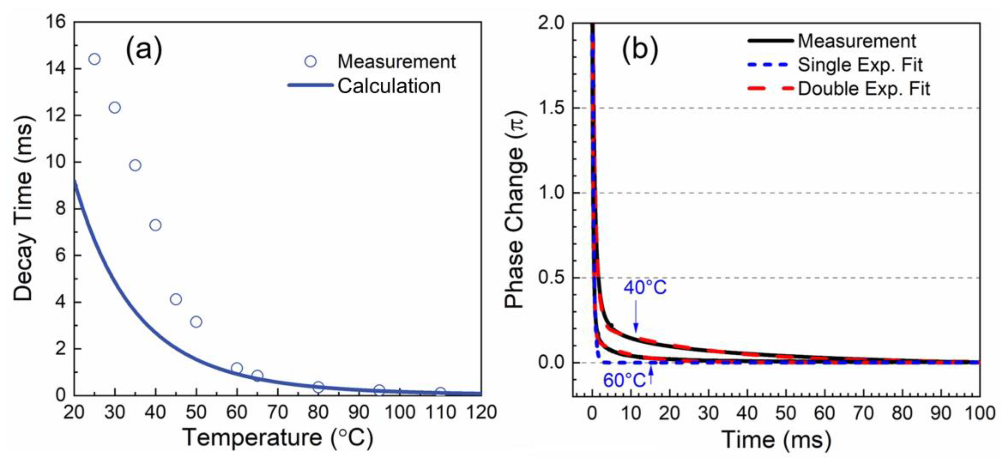
To measure relaxation time, we instantaneously removed the applied voltage V2π and recorded the transient phase change. The measured relaxation time was calculated between 90% and 10% phase change. Results for different operating temperatures are plotted in Figure 17a. At T = 40°C, the relaxation time was τ = 7.3 ms. If we raised the temperature to 60 °C, then the response time was reduced to τ =1.1 ms, which is valuable for laser beam steering devices. The fast response time at elevated temperatures was due to decreased γ1/K11 and double relaxation [99]. The solid line shown in Figure 17a is the calculated relaxation time of our PNLC device, according to the following equation [100]:
where A is a proportionality constant, kB is the Boltzmann constant, Ea is the activation energy, β is the material constant, and Tc is the clearing temperature. At an operating temperature above 60°C, the calculated results fit the experimental data well. At low temperatures, the measured relaxation time was slower than the calculated values. This discrepancy originates from double relaxation. For a polymer-stabilized system, two relaxation processes could take place simultaneously: LC director relaxation and the electrostriction effect of the polymer network. Thus, the relaxation time cannot be completely described by a single exponential term but, instead, by two exponential terms, as:
where the first and second terms represent the fast and slow relaxation processes, respectively, and [A, B] and [τ1, τ2] are the corresponding weights and free relaxation time constants, respectively. The fitting results are shown in Figure 17b. The degree of single relaxation can be quantified as the ratio A/(A + B). If the ratio reaches one (i.e., B = 0), we have single exponential decay, because the second term vanishes. For a stronger double relaxation case, B becomes larger, so that A/(A + B) is decreased. In our fitting, the ratio was 90% and the time constants were τ1 = 1.6 ms and τ2 = 52.4 ms at T = 40 °C. As the temperature increased to 60 °C, this ratio increased to 93% and the time constants were reduced to τ1 = 0.6 ms and τ2 = 18.0 ms, indicating a weaker double relaxation. Therefore, an elevated operating temperature helps to suppress the double relaxation and improve the response time of the PNLC device. To achieve a sub-millisecond response time, we could increase the monomer concentration to approximately 5 wt%, but the trade-off is an increased voltage [59].
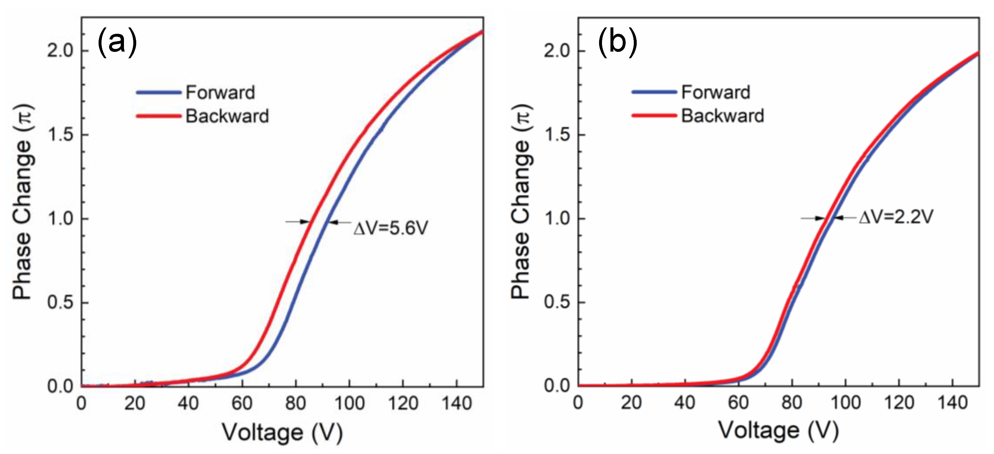
Elevated temperature operation not only improves response time, but also reduces hysteresis [99]. Hysteresis is a common phenomenon in polymer-stabilized liquid crystals. It affects grayscale control accuracy and should be minimized. Figure 18 plots the forward and backward voltage-dependent phase changes of the PNLC device at 40 °C and 60 °C, respectively. The hysteresis is calculated using following Equation (12):
In Equation (12), Vπ,F (Vπ,B) is the voltage at a π phase change for the forward (backward) scan. According to Figure 18, when the operating temperature increases from 40 °C to 60 °C, the hysteresis Δh decreases from 3.73% to 1.47%.
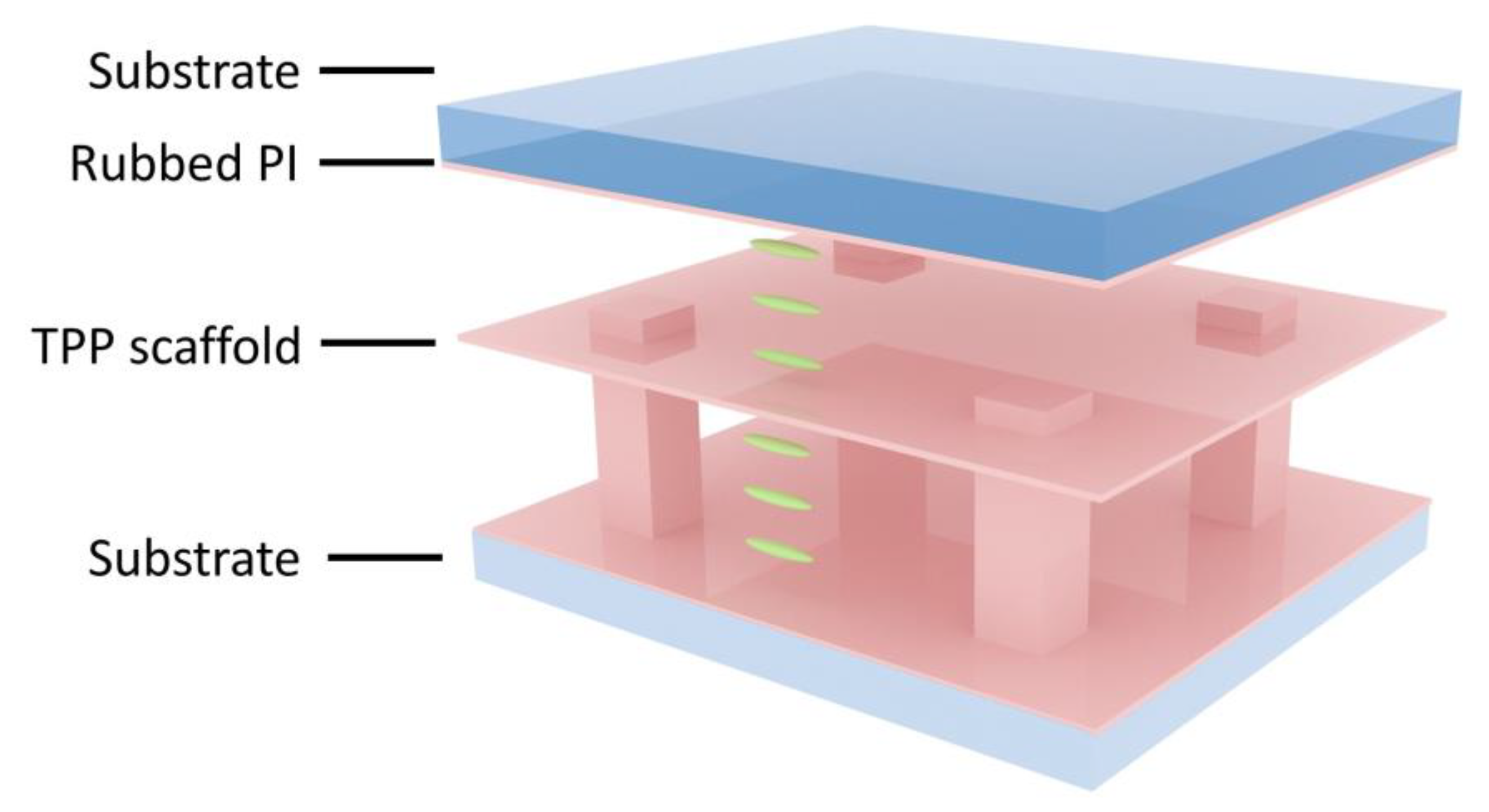
Besides PNLC, a well-designed scaffold by two-photon polymerization is another promising method to shorten the response time [101]. By artificially creating partition alignment layers in a cell, extra anchoring surfaces can be formed [101,102]. Figure 19 shows a two-layer device. By dividing the LC cell into two sub-layers, the response time should be 4x faster while keeping the same total phase change. Further separating the cell into N LC layers can theoretically obtain an N2 times faster response time. While the response time improves from the addition of more anchoring surfaces in a cell, the trade-off is increased voltage due to voltage shielding by the polymer partition layers. However, in comparison with PNLC, the major advantage of using a designed scaffold is that one can engineer the response time and driving voltage in a controllable way, as the working voltage increases linearly with the number of polymer anchoring layers. Experimentally, the response time improvements of two-layer and three-layer phase modulators, in reference to a single-layer phase modulator, were 4x and 7x (ideally, it should be 9x) faster, respectively. Some other advantages of multi-layer phase modulators, compared to PNLC, are reduced scattering and diminished hysteresis. Nevertheless, at present, the fabrication yield remains low.
4.2. Device Hybridization for Continuous, Large-Angle Beam Steering
Realizing continuous, large-angle beam steering devices with high efficiency has been a great challenge for decades. In Section 3, we introduced several devices but, still, none of them can fulfil these performance goals. For example, LC OPAs can achieve about 60% efficiency within a ±5° steering range with quasi-continuous steering angles, and LC-waveguide scanners can continuously scan within 50° (horizontal) by 15° (vertical) with more than 50% efficiency. To achieve a wider field of view, device hybridization is a potential approach.
A straightforward way is to cascade a continuous, tunable device with some discrete high-efficiency devices. For instance, combining an OPA with several PBDs and PVGs is a common approach to fulfill these requirements. Other methods have also been demonstrated, such as combining LC-waveguide scanners with PBDs [56]. Such a hybrid device will, undoubtedly, increase the driving complexity and device bulkiness. However, depending on the applications, these methods are still worth pursuing, because these non-mechanical beam steering devices are highly reliable with long lifetimes and low power consumption.
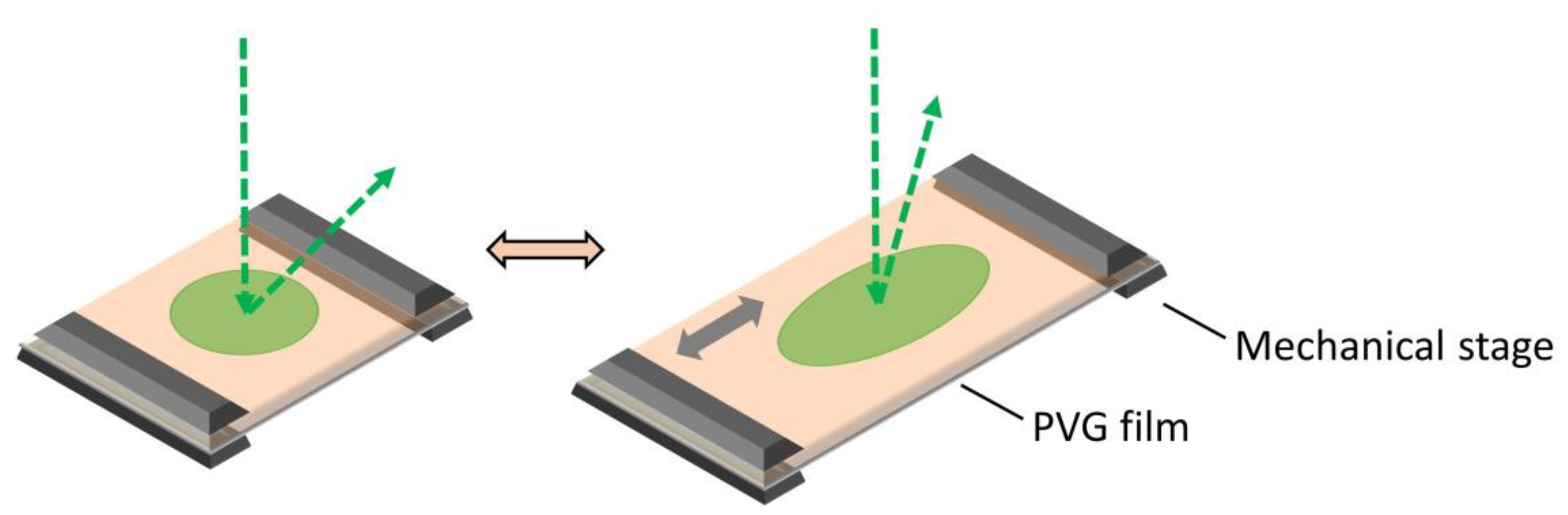
Another approach is to integrate some small-size electro-mechanical parts, such as MEMS mirrors, with some large-angle beam steerers, such as volume gratings. The utilization of small-size mechanical parts will improve the response time and reliability of the device, compared to the traditional, heavyweight mechanical beam steerers. It is worth mentioning that there have been other interesting hybridizations with mechanical parts, fully benefiting from the elasticity of LC polymers. As mentioned in Section 3.6, PVGs can achieve large diffraction angles with high efficiency. By replacing the substrate of PVGs from glass to PDMS, a stretchable PVG film has been developed [41,103]. Figure 20 depicts the working principle of the PVG film, where the green region depicts the effective grating area. When the PVG film is stretched mechanically along the gray arrow in Figure 20, the grating periodicity will continuously increase, and the corresponding diffraction angle will change accordingly. Releasing the strain will return the film to the un-strained state. However, the tuning range of this device is limited by the bandwidth of the PVGs. Although the diffraction angle of a PVG can reach 70°, the actual steering range is not as large. For example, if the diffraction angle (at a given wavelength) is designed to be 55°, then the maximum reachable steering angle by stretching is about 43.5°, which means that the tuning range is 12°. The response time is dependent on the speed of the mechanical motor and the lifetime of the device still needs further verification.
5. Conclusions
We have briefly reviewed the recent advances of LC beam steering devices, including three major operation mechanisms: Blazed gratings (Raman-Nath diffraction), volume gratings (Bragg reflection), and prisms (refraction). In light of these mechanisms, many devices have been proposed and demonstrated. Table 2 summarizes some key performance parameters of the six LC beam steerers mentioned above. For example, OPAs can quasi-continuously steer a laser beam within a ±5° range while keeping diffraction efficiency above 60%. Another promising approach is to use LC-cladding waveguides, which can continuously scan with a fast response time. Improving on the previously-established prism-type LC-cladding waveguide, we proposed a resistive electrode-enabled LC-cladding waveguide in this paper, which can potentially reduce device size. Rising PBDs and PVGs, with nearly 100% diffraction efficiencies, are also strong contenders. Although several devices exhibit high performance in the visible and near IR regions, to extend their useful applications into the MWIR and LWIR regions remains a challenge, with respect to properties such as response time and operation voltage. In this paper, we developed a new transmissive PNLC cell which can achieve a 2π phase change at λ = 4 μm with a reasonably fast response time; however, its operating voltage (approximately 140 Vrms) remains to be improved. Other techniques for addressing these issues are also emerging, such as using a TPP scaffold to create additional partition-anchoring layers in the device. In doing so, both a large phase change and fast response time can be obtained simultaneously. The problem is in the relatively slow fabrication process. On the other hand, to achieve the desired goal of continuous, large-angle beam steering with high efficiency, device hybridization could be a viable approach. We believe that the emergence of novel devices and hybridization methods, as well as the continuous improvement of existing devices, will significantly benefit future beam steering systems.
Author Contributions
Methodology, Z.H., F.G. and R.C.; writing—original draft preparation, Z.H., F.G., K.Y. and T.Z.; writing—review and editing, Z.H. and S.-T.W.; supervision, S.-T.W.
Funding
The authors are indebted to the financial support of Air Force Office of Scientific Research (AFOSR) under grant number FA9550-14-1-0279.
Conflicts of Interest
The authors declare no conflict of interest.
References
- Collis, R.T.H. Lidar. Appl. Opt. 1970, 9, 1782–1788. [Google Scholar] [CrossRef] [PubMed]
- Kattawar, G.W.; Plass, G.N. Time of flight lidar measurements as an ocean probe. Appl. Opt. 1972, 11, 662–666. [Google Scholar] [CrossRef]
- Hair, J.W.; Hostetler, C.A.; Cook, A.L.; Harper, D.B.; Ferrare, R.A.; Mack, T.L.; Welch, W.; Izquierdo, L.R.; Hovis, F.E. Airborne high spectral resolution lidar for profiling aerosol optical properties. Appl. Opt. 2008, 47, 6734–6752. [Google Scholar] [CrossRef] [PubMed]
- Van Kessel, P.F.; Hornbeck, L.J.; Meier, R.E.; Douglass, M.R. A MEMS-based projection display. Proc. IEEE 1998, 86, 1687–1704. [Google Scholar] [CrossRef]
- Lee, Y.H.; Zhan, T.; Wu, S.T. Enhancing the resolution of a near-eye display with a Pancharatnam-Berry phase deflector. Opt. Lett. 2017, 42, 4732–4735. [Google Scholar] [CrossRef]
- Tan, G.; Lee, Y.H.; Zhan, T.; Yang, J.; Liu, S.; Zhao, D.; Wu, S.T. Foveated imaging for near-eye displays. Opt. Express 2018, 26, 25076–25085. [Google Scholar] [CrossRef] [PubMed]
- Betzig, E.; Trautman, J.K. Near-field optics: Microscopy, spectroscopy, and surface modification beyond the diffraction limit. Science 1992, 257, 189–195. [Google Scholar] [CrossRef]
- Neuman, K.C.; Block, S.M. Optical trapping. Rev. Sci. Instrum. 2004, 75, 2787–2809. [Google Scholar] [CrossRef]
- Gattass, R.R.; Mazur, E. Femtosecond laser micromachining in transparent materials. Nat. Photonics 2008, 2, 219–225. [Google Scholar] [CrossRef]
- Lefsky, M.A.; Cohen, W.B.; Parker, G.G.; Harding, D.J. Lidar remote sensing for ecosystem studies. Bioscience 2002, 52, 19–30. [Google Scholar] [CrossRef]
- Næsset, E.; Gobakken, T.; Holmgren, J.; Hyyppä, H.; Hyyppä, J.; Maltamo, M.; Nilsson, M.; Olsson, H.; Persson, Å.; Söderman, U. Laser scanning of forest resources: The nordic experience. Scand. J. For. Res. 2004, 19, 482–499. [Google Scholar] [CrossRef]
- Goodman, J.L. History of space shuttle rendezvous and proximity operations. J. Spacecr. Rockets 2006, 43, 944–959. [Google Scholar] [CrossRef]
- Wehr, A.; Lohr, U. Airborne laser scanning—An introduction and overview. ISPRS J. Photogramm. Remote Sens. 1999, 54, 68–82. [Google Scholar] [CrossRef]
- Duncan, B.D.; Philip, J.B.; Vassili, S. Wide-angle achromatic prism beam steering for infrared countermeasure applications. Opt. Eng. 2003, 42, 1038–1047. [Google Scholar]
- Koh, K.H.; Kobayashi, T.; Lee, C. A 2-D MEMS scanning mirror based on dynamic mixed mode excitation of a piezoelectric PZT thin film S-shaped actuator. Opt. Express 2011, 19, 13812–13824. [Google Scholar] [CrossRef] [PubMed]
- Hofmann, U.; Janes, J.; Quenzer, H.J. High-Q MEMS resonators for laser beam scanning displays. Micromachines 2012, 3, 509–528. [Google Scholar] [CrossRef]
- Chan, T.K.; Megens, M.; Yoo, B.W.; Wyras, J.; Chang-Hasnain, C.J.; Wu, M.C.; Horsley, D.A. Optical beamsteering using an 8×8 MEMS phased array with closed-loop interferometric phase control. Opt. Express 2013, 21, 2807–2815. [Google Scholar] [CrossRef]
- Meyer, R.A. Optical beam steering using a multichannel lithium tantalite crystal. Appl. Opt. 1972, 11, 613–616. [Google Scholar] [CrossRef]
- Nimomiya, Y. Ultrahigh resolving electrooptical prism array light deflectors. IEEE J. Quantum Electron. 1973, 9, 791–795. [Google Scholar] [CrossRef]
- Davis, S.R.; Farca, G.; Rommel, S.D.; Martin, A.W.; Anderson, M.H. Analog, non-mechanical beam-steerer with 80 degrees field of regard. Proc. SPIE 2008, 6971, 69710G. [Google Scholar]
- Römer, G.; Bechtold, P. Electro-optic and acousto-optic laser beam scanners. Phys. Procedia 2014, 56, 29–39. [Google Scholar] [CrossRef]
- Smith, N.R.; Abeysinghe, D.C.; Haus, J.W.; Heikenfeld, J. Agile wide-angle beam steering with electrowetting microprisms. Opt. Express 2006, 14, 6557–6563. [Google Scholar] [CrossRef] [PubMed] [Green Version]
- Liu, C.; Li, L.; Wang, Q.H. Liquid prism for beam tracking and steering. Opt. Eng. 2012, 51, 114002. [Google Scholar] [CrossRef]
- Cheng, J.; Chen, C.L. Adaptive beam tracking and steering via electrowetting-controlled liquid prism. Appl. Phys. Lett. 2011, 99, 191108. [Google Scholar] [CrossRef]
- Kopp, D.; Lehmann, L.; Zappe, H. Optofluidic laser scanner based on a rotating liquid prism. Appl. Opt. 2016, 55, 2136–2142. [Google Scholar] [CrossRef] [PubMed]
- Resler, D.P.; Hobbs, D.S.; Sharp, R.C.; Friedman, L.J.; Dorschner, T.A. High-efficiency liquid-crystal optical phased-array beam steering. Opt. Lett. 1996, 21, 689–691. [Google Scholar] [CrossRef] [PubMed]
- Lindle, J.; Watnik, A.; Cassella, V. Efficient multibeam large-angle nonmechanical laser beam steering from computer-generated holograms rendered on a liquid crystal spatial light modulator. Appl. Opt. 2016, 55, 4336–4341. [Google Scholar] [CrossRef]
- McManamon, P.F.; Bos, P.J.; Escuti, M.J.; Heikenfeld, J.; Serati, S.; Xie, H.; Watson, E.A. A review of phased array steering for narrow-band electrooptical systems. Proc. IEEE 2009, 97, 1078–1096. [Google Scholar] [CrossRef]
- Yang, D.K.; Wu, S.T. Fundamentals of Liquid Crystal Devices; Wiley: Hoboken, NJ, USA, 2006. [Google Scholar]
- Kato, T.; Mizoshita, N.; Kishimoto, K. Functional liquid-crystalline assemblies: Self-organized soft materials. Angew. Chem. Int. Ed. Engl. 2005, 45, 38–68. [Google Scholar] [CrossRef]
- Woltman, S.J.; Jay, G.D.; Crawford, G.P. Liquid-crystal materials find a new order in biomedical applications. Nat. Mater. 2007, 6, 929–938. [Google Scholar] [CrossRef]
- Bisoyi, H.K.; Li, Q. Light-driven liquid crystalline materials: From photo-induced phase transitions and property modulations to applications. Chem. Rev. 2016, 116, 15089–15166. [Google Scholar] [CrossRef] [PubMed]
- McManamon, P.F.; Dorschner, T.A.; Corkum, D.L.; Friedman, L.J.; Hobbs, D.S.; Holz, M.; Liberman, S.; Nguyen, H.Q.; Pesler, D.P.; Sharp, R.C.; et al. Optical phased array technology. Proc. IEEE 1996, 84, 268–298. [Google Scholar] [CrossRef]
- Zohrabi, M.; Cormack, R.H.; Gopinath, J.T. Wide-angle nonmechanical beam steering using liquid lenses. Opt. Express 2016, 24, 23798–23809. [Google Scholar] [CrossRef] [PubMed] [Green Version]
- He, Z.; Lee, Y.H.; Chanda, D.; Wu, S.T. Adaptive liquid crystal microlens array enabled by two-photon polymerization. Opt. Express 2018, 26, 21184–21193. [Google Scholar] [CrossRef] [PubMed]
- He, Z.; Lee, Y.H.; Chen, R.; Chanda, D.; Wu, S.T. Switchable Pancharatnam-Berry microlens array with nano-imprinted liquid crystal alignment. Opt. Lett. 2018, 43, 5062–5065. [Google Scholar] [CrossRef] [PubMed]
- Nocentini, S.; Martella, D.; Wiersma, D.S.; Parmeggiani, C. Beam steering by liquid crystal elastomer fibres. Soft Matter 2017, 13, 8590–8596. [Google Scholar] [CrossRef] [PubMed]
- Li, C.C.; Chen, C.W.; Yu, C.K.; Jau, H.C.; Lv, J.A.; Qing, X.; Lin, C.F.; Cheng, C.Y.; Wang, C.Y.; Wei, J.; et al. Arbitrary beam steering enabled by photomechanically bendable cholesteric liquid crystal polymers. Adv. Opt. Mater. 2017, 5, 1600824. [Google Scholar] [CrossRef]
- Moharam, M.G.; Young, L. Criterion for Bragg and Raman-Nath diffraction regimes. Appl. Opt. 1978, 17, 1757–1759. [Google Scholar] [CrossRef]
- Saleh, B.; Teich, M. Fundamentals of Photonics; Wiley: New York, NY, USA, 2007. [Google Scholar]
- Yin, K.; Lee, Y.H.; He, Z.; Wu, S.T. Stretchable, flexible, rollable, and adherable polarization volume grating film. Opt. Express 2019, 27, 5814–5823. [Google Scholar] [CrossRef]
- Weng, Y.; Xu, D.; Zhang, Y.; Li, X.; Wu, S.T. Polarization volume grating with high efficiency and large diffraction angle. Opt. Express 2016, 24, 17746–17759. [Google Scholar] [CrossRef]
- Love, G.D.; Major, J.V.; Purvis, A. Liquid-crystal prisms for tip-tilt adaptive optics. Opt. Lett. 1994, 19, 1170–1172. [Google Scholar] [CrossRef] [PubMed]
- Wu, S.T.; Efron, U.; Hsu, T.Y. Near-infrared-to-visible image conversion using a Si liquid-crystal light valve. Opt. Lett. 1988, 13, 13–15. [Google Scholar] [CrossRef] [PubMed]
- Wang, X.; Wang, B.; Bos, P.J.; McManamon, P.F.; Pouch, J.J.; Miranda, F.A.; Anderson, J.E. Modeling and design of an optimized liquid-crystal optical phased array. J. Appl. Phys. 2005, 98, 073101. [Google Scholar] [CrossRef] [Green Version]
- McManamon, P.F. Agile nonmechanical beam steering. Opt. Photon. News 2006, 21–25. [Google Scholar] [CrossRef]
- Wang, X.; Wilson, D.; Muller, R.; Maker, P.; Psaltis, D. Liquid-crystal blazed-grating beam deflector. Appl. Opt. 2000, 39, 6545–6555. [Google Scholar] [CrossRef] [PubMed] [Green Version]
- Shang, X.; Tan, J.Y.; Willekens, O.; De Smet, J.; Joshi, P.; Cuypers, D.; Islamaj, E.; Beeckman, J.; Neyts, K.; Vervaeke, M.; et al. Electrically controllable liquid crystal component for efficient light steering. IEEE Photonics J. 2015, 7, 1–13. [Google Scholar] [CrossRef]
- Willekens, O.; Jia, X.; Vervaeke, M.; Shang, X.; Baghdasaryan, T.; Thienpont, H.; De Smet, H.; Neyts, K.; Beeckman, J. Reflective liquid crystal hybrid beam-steerer. Opt. Express 2016, 24, 21541–21550. [Google Scholar] [CrossRef]
- Klaus, W.; Ide, M.; Morokawa, S.; Tsuchiya, M.; Kamiya, T. Angle-independent beam steering using a liquid crystal grating with multi-resistive electrodes. Opt. Commun. 1997, 138, 151–157. [Google Scholar] [CrossRef]
- Shang, X.; Trinidad, A.M.; Joshi, P.; De Smet, J.; Cuypers, D.; De Smet, H. Tunable optical beam deflection via liquid crystal gradient refractive index generated by highly resistive polymer film. IEEE Photonics J. 2016, 8, 1–11. [Google Scholar] [CrossRef]
- Beeckman, J.; Nys, I.; Willekens, O.; Neyts, K. Optimization of liquid crystal devices based on weakly conductive layers for lensing and beam steering. J. Appl. Phys. 2017, 121, 023106. [Google Scholar] [CrossRef] [Green Version]
- Sun, J.; Xu, S.; Ren, H.; Wu, S.T. Reconfigurable fabrication of scattering-free polymer network liquid crystal prism/grating/lens. Appl. Phys. Lett. 2013, 102, 161106. [Google Scholar] [CrossRef]
- Ren, H.; Xu, S.; Wu, S.T. Gradient polymer network liquid crystal with a large refractive index change. Opt. Express 2012, 20, 26464–26472. [Google Scholar] [CrossRef] [PubMed]
- Davis, S.R.; Farca, G.; Rommel, S.D.; Johnson, S.; Anderson, M.H. Liquid crystal waveguides: New devices enabled by > 1000 waves of optical phase control. Proc. SPIE 2010, 7618, 76180E. [Google Scholar]
- Davis, S.R.; Rommel, S.D.; Johnson, S.; Anderson, M.H.; Anthony, W.Y. Liquid crystal clad waveguide laser scanner and waveguide amplifier for LADAR and sensing applications. Proc. SPIE 2015, 9365, 93650N. [Google Scholar]
- Frantz, J.A.; Myers, J.D.; Bekele, R.Y.; Spillmann, C.M.; Naciri, J.; Kolacz, J.; Gotjen, H.G.; Nguyen, V.Q.; McClain, C.C.; Shaw, L.B.; et al. Chip-based nonmechanical beam steerer in the midwave infrared. J. Opt. Soc. Am. B 2018, 35, C29–C37. [Google Scholar] [CrossRef]
- Peng, F.; Chen, H.; Tripathi, S.; Twieg, R.J.; Wu, S.T. Fast-response infrared phase modulator based on polymer network liquid crystal. Opt. Mater. Express 2015, 5, 265–273. [Google Scholar] [CrossRef] [Green Version]
- Gou, F.; Chen, R.; Hu, M.; Li, J.; Li, J.; An, Z.; Wu, S.T. Submillisecond-response polymer network liquid crystals for mid-infrared applications. Opt. Mater. Express 2018, 26, 29735–29743. [Google Scholar] [CrossRef]
- Tervo, J.; Turunen, J. Paraxial-domain diffractive elements with 100% efficiency based on polarization gratings. Opt. Lett. 2000, 25, 785–786. [Google Scholar] [CrossRef]
- Nikolova, L.; Todorov, T. Diffraction efficiency and selectivity of polarization holographic recording. Optica Acta 1984, 31, 579–588. [Google Scholar] [CrossRef]
- Pancharatnam, S. Generalized theory of interference, and its applications Part I: Coherent pencils. Proc. Indian Acad. Sci. A 1956, 44, 247–262. [Google Scholar] [CrossRef]
- Berry, M. Quantal phase factors accompanying adiabatic changes. Proc. R. Soc. London Ser. A 1984, 392, 45–57. [Google Scholar] [CrossRef]
- Oh, C.; Escuti, M.J. Numerical analysis of polarization gratings using the finite-difference time-domain method. Phys. Rev. A 2007, 76, 043815. [Google Scholar] [CrossRef] [Green Version]
- Lee, Y.H.; Tan, G.; Zhan, T.; Weng, Y.; Liu, G.; Gou, F.; Peng, F.; Tabiryan, N.V.; Gauza, S.; Wu, S.T. Recent progress in Pancharatnam-Berry phase optical elements and the applications for virtual/augmented realities. Opt. Data Process. Storage 2017, 3, 79–88. [Google Scholar] [CrossRef]
- Zhan, T.; Lee, Y.H.; Tan, G.; Xiong, J.; Yin, K.; Gou, F.; Zou, J.; Zhang, N.; Zhao, D.; Yang, J.; et al. Pancharatnam-Berry optical elements for head-up and near-eye displays. J. Opt. Soc. Am. B 2019, 36, D52–D65. [Google Scholar] [CrossRef]
- Sarkissian, H.; Park, B.; Tabirian, N.; Zeldovich, B. Periodically aligned liquid crystal: potential application for projection displays. Mol. Cryst. Liq. Cryst. 2006, 451, 1–19. [Google Scholar] [CrossRef]
- Kim, J.; Li, Y.; Miskiewicz, M.N.; Oh, C.; Kudenov, M.W.; Escuti, M.J. Fabrication of ideal geometric-phase holograms with arbitrary wavefronts. Optica 2015, 2, 958–964. [Google Scholar] [CrossRef]
- Zhan, T.; Xiong, J.; Lee, Y.H.; Chen, R.; Wu, S.T. Fabrication of Pancharatnam-Berry phase optical elements with highly stable polarization holography. Opt. Express 2019, 27, 2632–2642. [Google Scholar] [CrossRef] [Green Version]
- Ichimura, K. Photoalignment of liquid-crystal systems. Chem. Rev. 2000, 100, 1847–1874. [Google Scholar] [CrossRef] [PubMed]
- Nersisyan, S.R.; Tabiryan, N.V.; Steeves, D.M.; Kimball, B.R. The promise of diffractive waveplates. Opt. Photonics News 2010, 21, 40–45. [Google Scholar] [CrossRef]
- Kim, J.; Oh, C.; Serati, S.; Escuti, M.J. Wide-angle, nonmechanical beam steering with high throughput utilizing polarization gratings. Appl. Opt. 2011, 50, 2636–2639. [Google Scholar] [CrossRef]
- Chen, H.; Weng, Y.; Xu, D.; Tabiryan, N.V.; Wu, S.T. Beam steering for virtual/augmented reality displays with a cycloidal diffractive waveplate. Opt. Express 2016, 24, 7287–7298. [Google Scholar] [CrossRef] [Green Version]
- Gou, F.; Peng, F.; Ru, Q.; Lee, Y.H.; Chen, H.; He, Z.; Zhan, T.; Vodopyanov, K.L.; Wu, S.T. Mid-wave infrared beam steering based on high-efficiency liquid crystal diffractive waveplates. Opt. Express 2017, 25, 22404–22410. [Google Scholar] [CrossRef] [PubMed]
- Oh, C.; Escuti, M.J. Achromatic diffraction from polarization gratings with high efficiency. Opt. Lett. 2008, 33, 2287–2289. [Google Scholar] [CrossRef]
- Honma, M.; Nose, T. Temperature-independent achromatic liquid-crystal grating with spatially distributed twisted-nematic orientation. Appl. Phys. Express 2012, 5, 062501. [Google Scholar] [CrossRef]
- He, Z.; Tan, G.; Chanda, D.; Wu, S.T. Novel liquid crystal photonic devices enabled by two-photon polymerization. Opt. Express 2019, 27, 11472–11491. [Google Scholar] [CrossRef] [PubMed]
- Crawford, G.P.; Eakin, J.N.; Radcliffe, M.D.; Callan-Jones, A.; Pelcovits, R.A. Liquid-crystal diffraction gratings using polarization holography alignment techniques. J. Appl. Phys. 2005, 98, 123102. [Google Scholar] [CrossRef] [Green Version]
- Provenzano, C.; Pagliusi, P.; Cipparrone, G. Electrically tunable two-dimensional liquid crystals gratings induced by polarization holography. Opt. Express 2007, 15, 5872–5878. [Google Scholar] [CrossRef] [PubMed]
- Nys, I.; Beeckman, J.; Neyts, K. Switchable 3d liquid crystal grating generated by periodic photo-alignment on both substrates. Soft Matter 2015, 11, 7802–7808. [Google Scholar] [CrossRef] [PubMed]
- Nys, I.; Nersesyan, V.; Beeckman, J.; Neyts, K. Complex liquid crystal superstructures induced by periodic photo-alignment at top and bottom substrates. Soft Matter 2018, 14, 6892–6902. [Google Scholar] [CrossRef]
- Shi, L.; McManamon, P.F.; Bos, P.J. Liquid crystal optical phase plate with a variable in-plane gradient. J. Appl. Phys. 2008, 104, 033109. [Google Scholar] [CrossRef] [Green Version]
- Sutherland, R.L.; Natarajan, L.V.; Tondiglia, V.P.; Bunning, T.J. Bragg gratings in an acrylate polymer consisting of periodic polymer-dispersed liquid-crystal planes. Chem. Mater. 1993, 5, 1533–1538. [Google Scholar] [CrossRef]
- Liu, Y.J.; Sun, X.W. Holographic polymer-dispersed liquid crystals materials, formation, and applications. Adv. Optoelectron. 2008, 2008, 684349. [Google Scholar] [CrossRef]
- Lee, Y.H.; He, Z.; Wu, S.T. Optical properties of reflective liquid crystal polarization volume gratings. J. Opt. Soc. Am. B 2019, 36, D9–D12. [Google Scholar] [CrossRef]
- Kobashi, J.; Mohri, Y.; Yoshida, H.; Ozaki, M. Circularly-polarized, large-angle reflective deflectors based on periodically patterned cholesteric liquid crystals. Opt. Data Process. Storage 2017, 3, 61–66. [Google Scholar] [CrossRef]
- Lee, Y.H.; Yin, K.; Wu, S.T. Reflective polarization volume gratings for high efficiency waveguide-coupling augmented reality displays. Opt. Express 2017, 25, 27008–27014. [Google Scholar] [CrossRef] [PubMed]
- Xiang, X.; Kim, J.; Komanduri, R.; Escuti, M.J. Nanoscale liquid crystal polymer Bragg polarization gratings. Opt. Express 2017, 25, 19298–19308. [Google Scholar] [CrossRef]
- Gao, K.; McGinty, C.; Payson, H.; Berry, S.; Vornehm, J.; Finnemeyer, V.; Roberts, B.; Bos, P. High-efficiency large-angle Pancharatnam phase deflector based on dual-twist design. Opt. Express 2017, 25, 6283–6293. [Google Scholar] [CrossRef]
- Sakhno, O.; Gritsai, Y.; Sahm, H.; Stumpe, J. Fabrication and performance of efficient thin circular polarization gratings with Bragg properties using bulk photo-alignment of a liquid crystalline polymer. Appl. Phys. B 2018, 124, 52. [Google Scholar] [CrossRef]
- Chen, R.; Lee, Y.H.; Zhan, T.; Yin, K.; An, Z.; Wu, S.T. Multistimuli-responsive self-organized liquid crystal bragg gratings. Adv. Opt. Mater. 2019, 7, 1900101. [Google Scholar] [CrossRef]
- Xiang, X.; Kim, J.; Escuti, M.J. Bragg polarization gratings for wide angular bandwidth and high efficiency at steep deflection angles. Sci. Rep. 2018, 8, 7202. [Google Scholar] [CrossRef]
- Wu, S.T. Design of a liquid crystal based tunable electro-optic filter. Appl. Opt. 1989, 28, 48–52. [Google Scholar] [CrossRef] [PubMed]
- Wu, S.T. Birefringence dispersions of liquid crystals. Phys. Rev. A 1986, 33, 1270–1274. [Google Scholar] [CrossRef]
- Sun, J.; Wu, S.T. Recent advances in polymer network liquid crystal spatial light modulators. J. Polym. Sci. 2014, 52, 183–192. [Google Scholar] [CrossRef]
- Wu, S.T. Absorption measurements of liquid crystals in the ultraviolet, visible, and infrared. J. Appl. Phys. 1998, 84, 4462–4465. [Google Scholar] [CrossRef]
- Schadt, M. Liquid crystal materials and liquid crystal displays. Annu. Rev. Mater. Sci. 1997, 27, 305–379. [Google Scholar] [CrossRef]
- Serati, S.A.; Xia, X.; Mughal, O.; Linnenberger, A. High-resolution phase-only spatial light modulators with submillisecond response. Proc. SPIE 2003, 5106, 138–145. [Google Scholar]
- Kneppe, H.; Schneider, F.; Sharma, N.K. Rotational viscosity γ1 of nematic liquid crystals. J. Chem. Phys. 1982, 77, 3203–3208. [Google Scholar] [CrossRef]
- Kikuchi, H.; Nishiwaki, J.; Kajiyama, T. Mechanism of electro-optical switching hysteresis for (polymer/liquid crystal) composite films. Polym. J. 1995, 27, 1246–1256. [Google Scholar] [CrossRef]
- Lee, Y.H.; Franklin, D.; Gou, F.; Liu, G.; Peng, F.; Chanda, D.; Wu, S.T. Two-photon polymerization enabled multi-layer liquid crystal phase modulator. Sci. Rep. 2017, 7, 16260. [Google Scholar] [CrossRef]
- He, Z.; Lee, Y.H.; Gou, F.; Franklin, D.; Chanda, D.; Wu, S.T. Polarization-independent phase modulators enabled by two-photon polymerization. Opt. Express 2017, 25, 33688–33694. [Google Scholar] [CrossRef]
- Yin, K.; Lee, Y.H.; He, Z.; Wu, S.T. Stretchable, flexible, and adherable polarization volume grating film for waveguide-based augmented reality displays. J. Soc. Inf. Disp. 2019, 27, 232–237. [Google Scholar] [CrossRef]
Figure 1.
Schematic drawing of a grating in the Raman-Nath regime. Multiple diffraction orders in both the forward (blue arrows) and backward (black arrows) directions coexist.
Figure 1.
Schematic drawing of a grating in the Raman-Nath regime. Multiple diffraction orders in both the forward (blue arrows) and backward (black arrows) directions coexist.

Figure 2.
Illustration of beam steering based on (a) variable-period and (b) variable diffraction order blazed gratings.
Figure 2.
Illustration of beam steering based on (a) variable-period and (b) variable diffraction order blazed gratings.

Figure 3.
(a) Schematic sketch of Bragg reflection in a periodic structure, and (b) a liquid crystal (LC) Bragg grating based on a helical cholesteric structure.
Figure 3.
(a) Schematic sketch of Bragg reflection in a periodic structure, and (b) a liquid crystal (LC) Bragg grating based on a helical cholesteric structure.

Figure 4.
Schematic diagram of a prismatic beam deflector; δ is the deviation angle.

Figure 5.
After passing through the optical phase array (OPA), the designed step-wise phase profile is distorted, especially in the flyback regions.
Figure 5.
After passing through the optical phase array (OPA), the designed step-wise phase profile is distorted, especially in the flyback regions.

Figure 6.
Two device configurations of compound blazed gratings: (a) Transmissive mode and (b) reflective mode. At a large applied voltage, the transmissive mode will direct light to small diffraction orders, while the reflective one will guide light to large diffraction orders. The incident linear polarization is parallel to the LC alignment direction.

Figure 7.
Layout of the resistive electrode-based beam steerer. The dashed rectangle depicts the top view of the top electrodes.
Figure 7.
Layout of the resistive electrode-based beam steerer. The dashed rectangle depicts the top view of the top electrodes.

Figure 8.
Schematic plot of the LC-cladding waveguide beam steerer, proposed by Vescent Photonics.

Figure 9.
Schematic drawing of the LC-cladding waveguide beam steerer based on resistive electrodes. The major difference from the Vescent Photonics device is the structure of the top electrodes, where structure I uses a single resistive electrode and structure II uses an array of resistive electrodes.

Figure 10.
Simulation results of steering angle versus refractive index differences for both case 1 (black) and case 2 (red).
Figure 10.
Simulation results of steering angle versus refractive index differences for both case 1 (black) and case 2 (red).

Figure 11.
Schematic illustration of the structure of (a) a passive Pancharatnam-Berry deflector (PBD) made of a liquid crystal polymer, and (b) an active PBD made of liquid crystal at voltage-off and voltage-on states. PAL, photo-alignment layer; S, substrate.
Figure 11.
Schematic illustration of the structure of (a) a passive Pancharatnam-Berry deflector (PBD) made of a liquid crystal polymer, and (b) an active PBD made of liquid crystal at voltage-off and voltage-on states. PAL, photo-alignment layer; S, substrate.

Figure 12.
Schematic illustration of the two beam steering approaches using PBD: (a) Input polarization switch (i.e., a passive switch), and (b) PBD structure switching between on and off states (i.e., an active switch).
Figure 12.
Schematic illustration of the two beam steering approaches using PBD: (a) Input polarization switch (i.e., a passive switch), and (b) PBD structure switching between on and off states (i.e., an active switch).

Figure 13.
(a) Schematic illustration of the LC director distribution in a reflective polarization volume grating (PVG). The yellow dashed lines highlight the Bragg period. (b) Polarization selectivity of a right-handed reflective PVG.
Figure 13.
(a) Schematic illustration of the LC director distribution in a reflective polarization volume grating (PVG). The yellow dashed lines highlight the Bragg period. (b) Polarization selectivity of a right-handed reflective PVG.

Figure 14.
Schematic plot of an electrically-controlled reflective PVG device. Under a 50 V driving voltage, it can be switched between Bragg grating and homeotropic state by applying different AC frequencies.
Figure 14.
Schematic plot of an electrically-controlled reflective PVG device. Under a 50 V driving voltage, it can be switched between Bragg grating and homeotropic state by applying different AC frequencies.

Figure 15.
(a) Birefringence dispersion of UCF-13 at room temperature: Dots are the measured data and the solid line is the fitting curve using the single-band bi-refringence dispersion equation. (b) Measured transmittance spectrum of UCF-13 with a cell gap of about 30 μm.
Figure 15.
(a) Birefringence dispersion of UCF-13 at room temperature: Dots are the measured data and the solid line is the fitting curve using the single-band bi-refringence dispersion equation. (b) Measured transmittance spectrum of UCF-13 with a cell gap of about 30 μm.

Figure 16.
Voltage-dependent phase change of our transmissive polymer network LC (PNLC) device at λ = 4 μm and cell gap 27.5 μm.
Figure 16.
Voltage-dependent phase change of our transmissive polymer network LC (PNLC) device at λ = 4 μm and cell gap 27.5 μm.

Figure 17.
(a) Temperature-dependent relaxation time for 2π phase change of our PNLC device. Dots represent the measured data and the solid line is the calculated result using Equation 10. (b) Transient relaxation process of the PNLC sample at T = 40 °C and 60 °C, fitted with single (dashed blue line) and double (dashed red line) relaxation equations.

Figure 18.
Forward and backward voltage-dependent phase changes of PNLC device at (a) T = 40 °C and (b) T = 60 °C. In both cases, λ = 4 μm and cell gap 27.5 μm.
Figure 18.
Forward and backward voltage-dependent phase changes of PNLC device at (a) T = 40 °C and (b) T = 60 °C. In both cases, λ = 4 μm and cell gap 27.5 μm.

Figure 19.
Configuration of a two-layer LC device. The additional polymer anchoring layer with pillar supports can be generated by two-photon polymerization. PI, (polyimide); TPP, (two-photon polymerization).
Figure 19.
Configuration of a two-layer LC device. The additional polymer anchoring layer with pillar supports can be generated by two-photon polymerization. PI, (polyimide); TPP, (two-photon polymerization).

Figure 20.
Schematic diagram of a mechanically controlled PVG film for continuous beam steering.


Table 1.
Chemical structures and compositions of the proposed mixture UCF-13.
| Compound No. | Chemical Structure | Weight (wt%) |
|---|---|---|
| 1 |  | 70% |
| 2 |  | |
| 3 |  | 20% |
| 4 |  | 10% |
Table 2.
Key parameters of some recently-developed LC beam steering devices.
| Devices | Range (⁰) | Efficiency | Continuity | Decay time | λ (μm) | Ref. |
|---|---|---|---|---|---|---|
| OPAs | ±5 | ~60% | Quasi-continuous | a | b | [28,33] |
| Compound blazed gratings | 0–2.3 | ~40% | Discrete | ~ 100’s ms | 0.532 | [48] |
| 32.1–37.4 | ~40% | Discrete | ~ 100’s ms | 0.633 | [49] | |
| Resistive electrodes | ±4.8 | NA | Discrete | ~ 1’s s | 0.532 | [51] |
| LC-cladding waveguides | ±50 | >50% | Continuous | <1 ms | 1.55 | [56] |
| ±7 | NA | Continuous | NA | 4.6 | [57] | |
| ±4.9 | >90% (c) | Continuous | d | 1.55 | This work | |
| PBDs | ±22 | >90% | Discrete | ~ 1’s ms | 1.55 | [72] |
| ±7.6 | >90% | Binary | 10 ms | 4 | [74] | |
| PVGs | 0–55 | >96% | Binary | 1.4 ms | 0.532 | [91] |
| 43.5–55 | >90% | Continuous | e | 0.532 | [41] |
ab. these two parameters depend on each other, as indicated in Equations (8) and (9); c: the simulated result is only for reference; d: response time depends on the choice of LC materials and a <1 ms response time is achievable; e: response time depends on the mechanical motor.
© 2019 by the authors. Licensee MDPI, Basel, Switzerland. This article is an open access article distributed under the terms and conditions of the Creative Commons Attribution (CC BY) license (http://creativecommons.org/licenses/by/4.0/).
Share and Cite
MDPI and ACS Style
He, Z.; Gou, F.; Chen, R.; Yin, K.; Zhan, T.; Wu, S.-T. Liquid Crystal Beam Steering Devices: Principles, Recent Advances, and Future Developments. Crystals 2019, 9, 292. https://doi.org/10.3390/cryst9060292
AMA Style
He Z, Gou F, Chen R, Yin K, Zhan T, Wu S-T. Liquid Crystal Beam Steering Devices: Principles, Recent Advances, and Future Developments. Crystals. 2019; 9(6):292. https://doi.org/10.3390/cryst9060292
Chicago/Turabian StyleHe, Ziqian, Fangwang Gou, Ran Chen, Kun Yin, Tao Zhan, and Shin-Tson Wu. 2019. "Liquid Crystal Beam Steering Devices: Principles, Recent Advances, and Future Developments" Crystals 9, no. 6: 292. https://doi.org/10.3390/cryst9060292
Note that from the first issue of 2016, this journal uses article numbers instead of page numbers. See further details here.