Cost-Effective Surface Modification of Carbon Cloth Electrodes for Microbial Fuel Cells by Candle Soot Coating


Department of Chemical and Materials Engineering, National I-Lan University, I-Lan 260, Taiwan
*
Author to whom correspondence should be addressed.
Coatings 2018, 8(12), 468; https://doi.org/10.3390/coatings8120468
Submission received: 7 November 2018
/
Revised: 10 December 2018
/
Accepted: 16 December 2018
/
Published: 17 December 2018
(This article belongs to the Special Issue Surface Chemical Modification)
Abstract
:This study explored an economically-feasible and environmentally friendly attempt to provide more electrochemically promising carbon cloth anodes for microbial fuel cells (MFCs) by modifying them with candle soot coating. The sponge-like structure of the deposited candle soot apparently increased the surface areas of the carbon cloths for bacterial adhesion. The super-hydrophilicity of the deposited candle soot was more beneficial to bacterial propagation. The maximum power densities of MFCs configured with 20-s (13.6 ± 0.9 mW·m−2), 60-s (19.8 ± 0.2 mW·m−2), and 120-s (17.6 ± 0.8 mW·m−2) candle-soot-modified carbon cloth electrodes were apparently higher than that of an MFC configured with an unmodified electrode (10.2 ± 0.2 mW·m−2). The MFCs configured with the 20- and 120-s candle-soot-modified carbon cloth electrodes exhibited lower power densities than that of the MFC with the 60-s candle-soot-modified carbon cloth electrode. This suggested that the insufficient residence time of candle soot led to an incomplete formation of the hydrophilic surface, whereas protracted candle sooting would lead to a thick deposited soot film with a smaller conductivity. The application of candle soot for anode modification provided a simple, rapid, cost-effective, and environment-friendly approach to enhancing the electron-transfer capabilities of carbon cloth electrodes. However, a postponement in the MFC construction may lead to a deteriorated hydrophilicity of the candle-soot-modified carbon cloth.
1. Introduction
Microbial fuel cells (MFCs) are an environmentally friendly option for alternative-energy applications, as they can convert chemically bound energy into biomass-based electricity by electroactive bacteria during a wastewater treatment [1,2,3,4]. MFCs can also be applied in the removal of toxic pollutants, in environmental sensors, in harvesting the energy stored in marine sediments, in bioremediation, and in desalination [3]. Recently, MFCs are utilized as a simultaneous power source of self-powered electrochemical biosensors, because no potentiostat, power for the potentiostat, and/or power for the signaling device are needed [5]. However, there are still some challenges that need to be resolved in the practical applications of MFCs, including low power generation, the cost of anode materials for large-scale applications, system development, and energy recovery [6,7]. Furthermore, the low extracellular electron transfer efficiency between the microorganism and the electrode is the main bottleneck limiting the practical applications of MFCs [8]. Therefore, it is important to improve electrode properties by a surface treatment to enhance the extracellular electron transfer efficiency at the anode. Electrochemically active bacteria generate bioelectricity through three mechanisms: A direct electron transport through membrane-bound proteins, conductive nanowires, and indirect shuttles through redox mediators [9]. As bacteria play a crucial role in the generation of bioelectricity, the characteristics of anode electrodes are crucial for bacterial attachment to have a power generation capability in the cost-effective operations of MFCs [10,11]. Compared to other materials, carbonaceous electrodes are typically suitable as anodes of MFCs, owing to their high conductivities, good biocompatibilities, excellent chemical stabilities, and relatively low costs [12,13]. However, the undesirable hydrophobicity of the carbonaceous electrodes normally leads to a high resistance of electron transfer and low bioelectricity-generating efficiency.
To solve such technical problems, numerous studies demonstrated that appropriate modifications upon the carbonaceous electrode surface seem to effectively improve electron-transfer characteristics and power-generating performances of MFCs [10,11,12,13,14]. For example, Cheng and Logan [14] used an ammonia treatment to increase the positive charges on the surfaces of carbon cloth electrodes and obtained a maximum power density of 1970 mW·m−2. Feng et al. [15] reported that the power generation of MFCs could be improved by an acid soaking of carbon fibers and approached a maximum power density of 1370 mW·m−2. Lowy et al. [16] and Tang et al. [17] demonstrated that the performances of MFCs could be improved by an electrochemical oxidation treatment of graphite electrodes. Lowy et al. [16] reported that the quinone-modification of previously oxidized graphite electrodes yielded an increase of the kinetic activity by a factor of 218. Tang et al. [17] showed that MFCs with electrochemically oxidized graphite felt anodes produced a current of 1.13 mA, 39.5% higher compared with that of MFCs containing untreated anodes. Chang et al. [18] reported that carbon cloth electrodes exhibited superior surface and electrochemical properties after a modification by atmospheric-pressure plasma jets. According to their study, the maximum power density of the MFCs could be increased from 2.38 to 7.56 mW·m−2 after modification. In addition, the surface properties of anode electrodes can be improved by coating them with carbon nanotubes [19], ferric oxides [20], Au nanoparticles [21], goethite nanowhiskers [22], NiO nanoflake arrays [23], reduced graphene oxides [24], and tungsten carbide [25]. However, most of these surface modification methods are time consuming, less economically feasible, or not environmentally appropriate, due to the use of chemicals that are potentially harmful to the environment.
Candle soot particles are tiny, unburned carbon that originated from the incomplete combustion of easily available candles. Recently, candle soot has been widely implemented in solar and fuel cell applications owing to its low cost, rapid and simple preparation, non-toxicity, high specific surface area, and good conductivity [26,27,28,29]. For example, Wei et al. [26] have developed cost-efficient, environmentally stable clamping solar cells by using candle soot for the hole extraction from ambipolar perovskites. Kakunuri and Sharma [27] reported a simple and inexpensive approach to synthesizing a fractal-like interconnected network of carbon nanoparticles from candle soot, used as an anode material for a high-rate lithium-ion battery. Khalakhan et al. [28] reported that the elementary preparation, high specific surface area, good conductivity, and hydrophobicity make candle soot a promising material for the support of the proton-exchange-membrane fuel-cell catalyst. Liang et al. [29] reported that ultrafine soot particles formed in the flame tip region of a candle are composed of elemental carbon and ash, have a large specific surface area, and are hydrophilic. Evidently, the hydrophilicity and large specific surface area of the flame-tip soot particles suggested that they were likely promising for the surface modification of carbonadoes electrodes in MFCs. Nevertheless, no extensive studies on the applications of candle soot have been reported for MFCs. Singh et al. [30] reported for the first time the use of candle soot to modify the electrodes of MFCs. They successfully fabricated an ultrafine stainless steel wire disk deposited by carbon nanoparticles derived from candle soot as the electrode of an MFC and demonstrated that such modified MFC could provide a high capability for bioenergy extraction. Although stainless steels own excellent corrosion resistances, long-term interactions between stainless steel and living organisms might still cause corrosion of the steel’s chromium oxide layer, leading to the release of metal ions and the inhibition of microbial growth. Here, carbon nanoparticles were coated with candle soot, but they were directly deposited on the surfaces of carbon cloths. The surface properties of the candle-soot-modified carbon cloths with various duration of times were studied for the maximal power generation of MFCs.
2. Materials and Methods
2.1. Construction of MFCs
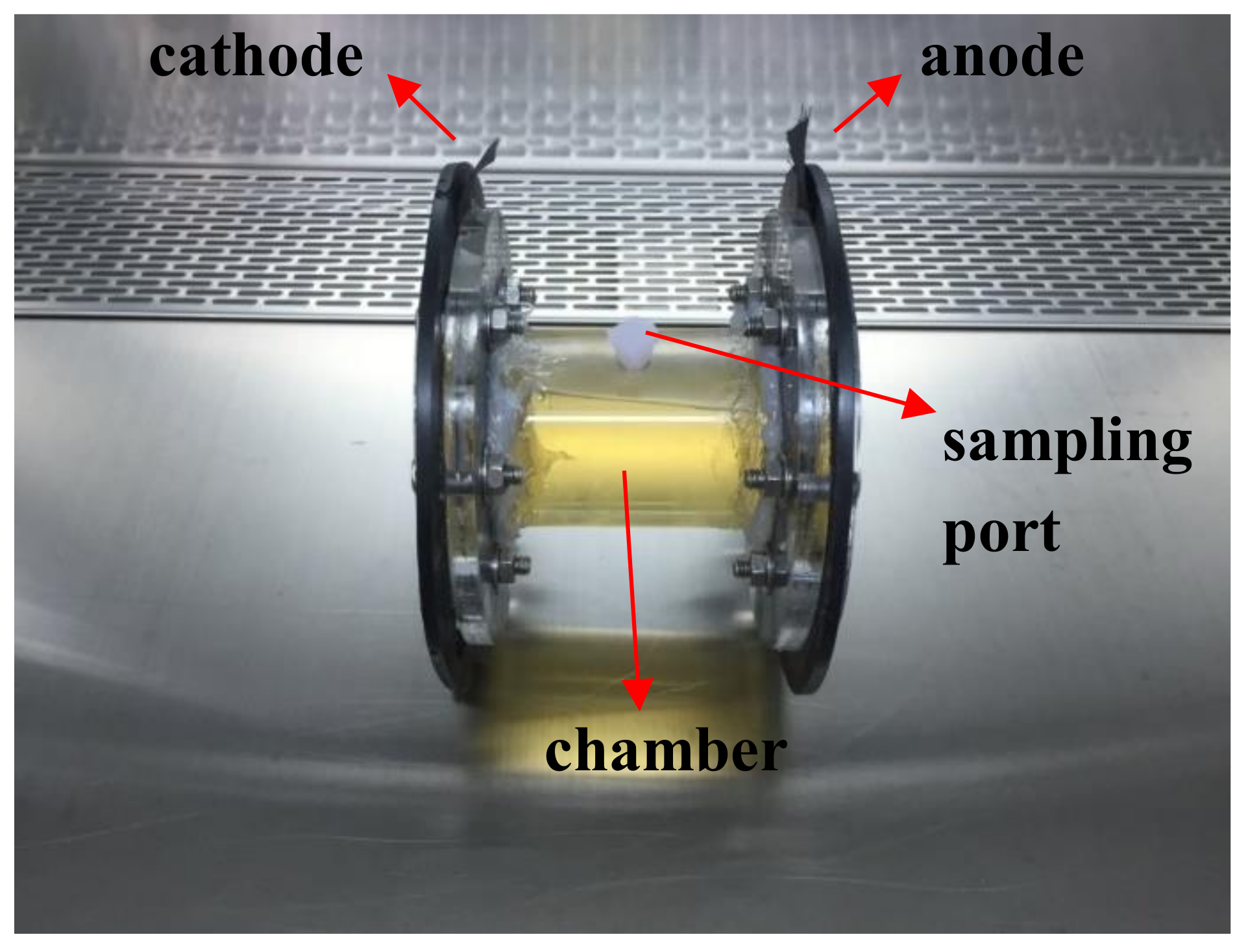
Membrane-free air-breathing cathode single-chamber MFCs were adopted as described elsewhere [31]. The MFCs were constructed in cylindrical tubes made of poly(methyl methacrylate) with an operating volume of 220 mL. The anodes of the MFCs were carbon cloths (without waterproofing or catalyst) with projected areas of approximately 22.9 cm2. The sizing of the air cathodes had dimensions approximately equal to those of the anodes and comprised a polytetrafluoroethylene diffusion layer on the air-facing side. Both carbon cloth and polytetrafluoroethylene diffusion layer were purchased from CeTech, Taichung, Taiwan. Figure 1 shows the photography of the membrane-free air-breathing cathode single-chamber MFC used in this study. Some of the carbon cloth anodes were directly placed into the candle flame tip region for 20, 60, and 120 s prior to the construction of MFCs. To consider the economic feasibility for sustainable development, the candles used were without further treatment and purchased from a common grocery store in I-Lan, Taiwan.
2.2. Experimental Operations
Acclimation step: the microbe used in MFCs was Aeromonas hydrophila NIU01. The Luria–Bertani (LB) broth medium (tryptone: 10 g·L−1, yeast extract: 5 g·L−1, and sodium chloride: 10 g·L−1) was used as the culture medium in the MFCs. Approximately 5 mL of a concentrated O/N cultured biomass was mixed with 0.2 × LB in MFCs for acclimatization. For a serial acclimation, approximately 5 mL of the cell broth were replaced by an impulse injection with a fresh sterile 8.8 × LB medium every 48 h. The output voltage of the MFC was continuously monitored to determine whether stable bioelectricity-generating profiles were achieved to guarantee success of electrochemical acclimatization. Then, the steady-state output power generation of MFCs was approximately achieved after approx. 30 days acclimation.
Experimental step: The batch-fed mode of MFC operation with impulse injection of energy substrate was carried out at 25 °C every 7 days. That is, 5.0 mL of 8.8 × LB broth laden was supplemented to MFCs to maintain culture medium in 0.2 × LB for inspection. Approx. 1 h after impulse injection of energy substrate, the supplemented medium was considered to be well-distributed in MFC and then electrochemical analysis of MFCs was conducted.
2.3. Characterizations
The surface and cross-sectional morphologies of the candle-soot-modified carbon cloths were measured with a scanning electron microscope (SEM) (5136MM, Tescan, Kohoutovice, Czech Republic). The surface wettabilities of the candle-soot-modified carbon cloths were measured using the sessile drop method by a contact-angle instrument (FTA125, First Ten Ångstroms, Portsmouth, OH, USA). Digital images of deionized-water droplets with volumes of approximately 10 μL were captured after the droplet on the film reached a steady state (approximately 5 s) to determine the equilibrium sessile contact angle. The average contact angle was determined by averaging 7 random measurements at different locations on the film, excluding outlier-data values. The surface chemical compositions of the candle-soot-modified carbon cloths were analyzed using an X-ray photoelectron spectrometer (XPS) (K-Alpha, Thermo Scientific, Waltham, MA, USA) with a monochromatic Al Kα radiation source (1468.6 eV). Survey spectra of the specimens were acquired in the range of 0–1000 eV with steps of 1 eV. C1s and O1s spectra of the specimens were measured in steps of 0.05 eV. The power-generating capabilities of the MFC were evaluated using an electrochemical workstation (ZIVE SP1, WonAtech, Seoul, Korea). The MFC voltage was automatically measured with an external resistance of Rout = 1000 Ω for comparison purpose. The power and current densities of each MFC were determined by linear sweep voltammetry (LSV) measurements at a scan rate of 0.1 mV·s−1; the corresponding voltages were recorded using a multimeter (ZIVE SP1, WonAtech, Seoul, Korea). All of the MFC experimental tests were carried out at ambient temperature. The average power density was calculated from 7 replicated-measurements. The internal resistance of the MFC was measured by electrochemical impedance spectroscopy (EIS) at open-circuit voltage conditions in a frequency range of 0.005–100,000 Hz at an amplitude of 10 mV.
3. Results
3.1. Surface Morphologies
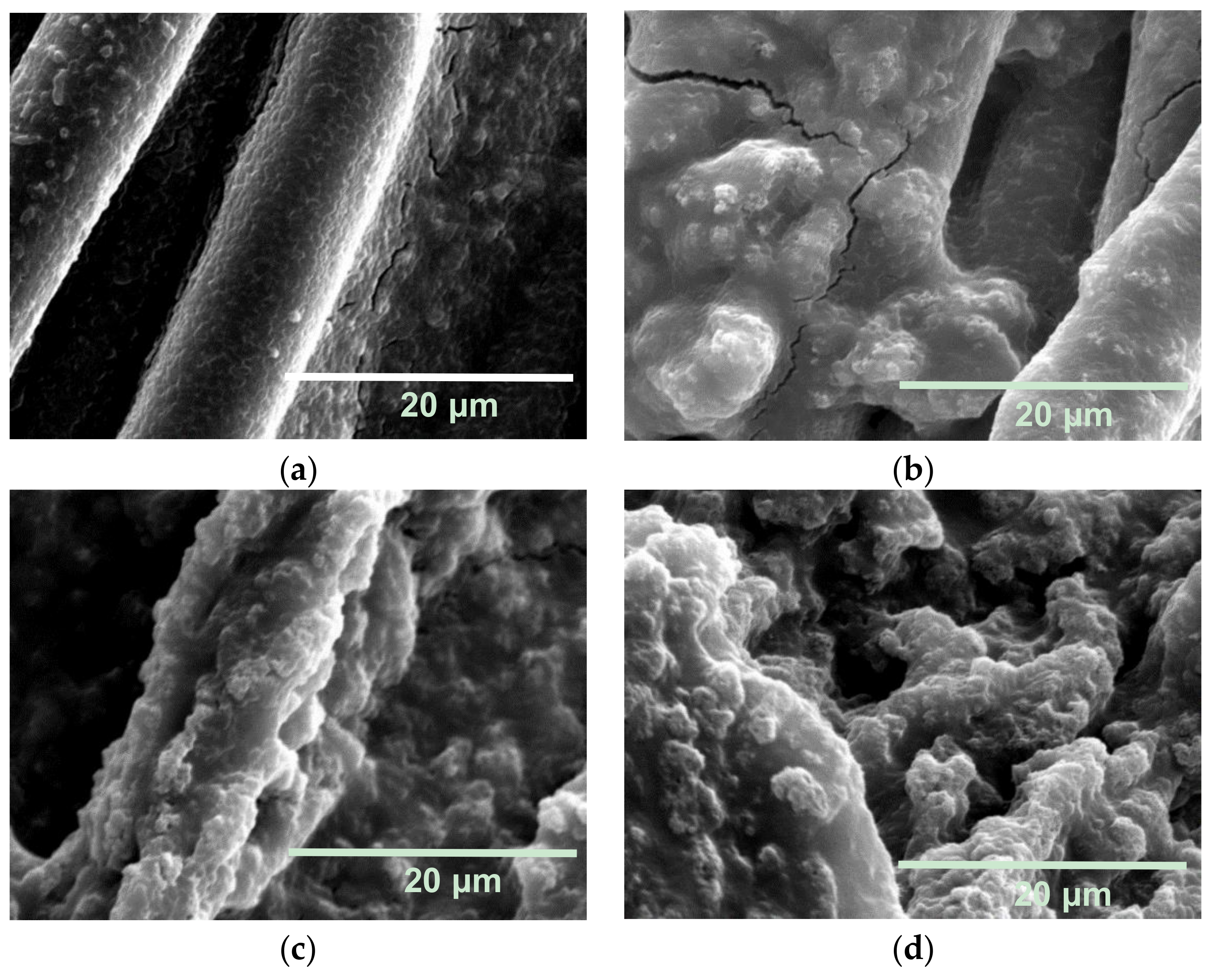
Figure 2a–d exhibits top-view SEM images of the unmodified carbon cloth and those modified by 20, 60, and 120 s of candle sooting, respectively. Figure 2a shows that the unmodified carbon cloth comprises smooth carbon fibers with diameters of ca. 10 μm. Figure 2b shows the diameters of the carbon fibers increased to approximately 20 μm after 20 s of candle sooting, indicating that some candle soot particles were deposited on the surfaces of the carbon fibers. Figure 2c reveals that the carbon fibers of the carbon cloth modified by 60 s of candle sooting were apparently thicker than those modified for 20 s. It clearly suggested that more abundant soot particles were deposited on the surface of the carbon cloth. Figure 2d shows that the carbon cloth was densely covered by soot particles after the 120 s of candle sooting. In addition, the morphologies of the carbon fibers became characterless. According to Figure 2a–d, it was concluded that the number of deposited soot particles significantly increased with the residence time for candle soot. Figure 2e,f shows magnified SEM images of the carbon cloths modified by 60 s (Figure 2c) and 120 s (Figure 2d) of candle sooting, respectively. Figure 2e,f demonstrates that both deposited soot particles exhibited sponge-like structures. This suggests that the surface areas of the carbon cloths could be effectively increased for a microbial attachment after the modification by candle soot, if the biotoxicity potency of modified cloths were not significantly augmented.
Figure 3a–d presents cross-sectional SEM images of the unmodified carbon cloth and those modified by 20, 60, and 120 s of candle sooting, respectively. Figure 3a shows that the thickness of the unmodified carbon cloth was approximately 200 μm. Figure 3b reveals that some soot particles were deposited on the surface of the carbon cloth; however, they seemed to not be very uniformly distributed. Figure 3c,d shows that more abundant soot particles were deposited on the surfaces of the carbon cloths, forming dense candle soot films after the candle sootings for 60 and 120 s, respectively. Figure 3 also elucidates that carbon fibers in the carbon cloths were not fractured or attenuated during candle soot modification.
3.2. Wettability
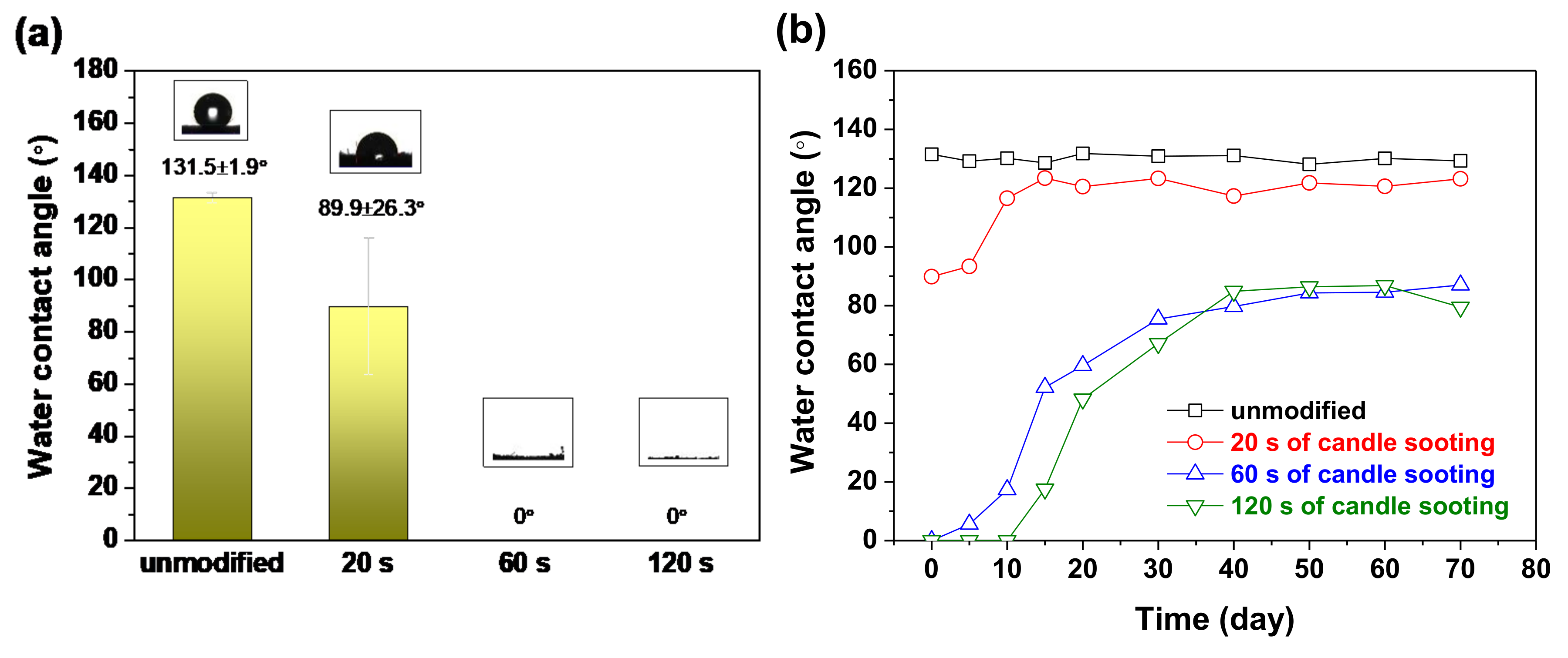
Figure 4a shows the water contact angle measurement results of the unmodified and candle-soot-modified carbon cloths. As shown in Figure 4a, unmodified carbon cloth exhibited a high-water contact angle of approximately 131.5° ± 1.9°, indicating that the surface of the as-received carbon cloth was highly hydrophobic. After 20 s of candle sooting, the water contact angle of the carbon cloth decreased to approximately 89.9° ± 26.3°. The high standard deviation (±26.3°) could be explained by the fact that the deposited soot particles were not uniformly distributed on the surface of the carbon cloth (Figure 3b). Figure 4a also shows that the water contact angles of the carbon cloths modified by 60 and 120 s of candle sooting approached the value of zero, suggesting that the carbon cloths tended to be highly hydrophilic with a sufficient time of candle sooting.
To evaluate the feasible duration to stably maintain such a hydrophilicity of the modified carbon cloths, the altered carbon cloths were exposed in ambient environment after the candle sooting and the water contact angles of these cloths were determined every five days. Apparently, as Figure 4b revealed, the water contact angles of the unmodified and candle-soot-modified carbon cloths could be found as a function of exposure time. As shown in Figure 4b, the water contact angle of the untreated carbon cloth was maintained at approximately 130° throughout 70 days. On the other hand, the water contact angle of the 20-s candle-soot-modified carbon cloth gradually increased from approximately 90° to 120° during exposure in the presence of ambient air for 10 days. Although the water contact angles of the 60- and 120-s candle-soot-modified carbon cloths were nearly 0° immediately after surface modification, their high hydrophilicities began to deteriorate after exposure to ambient air for five days. Henceforth, their water contact angles gradually increased to approximately 80° after 40 days. Nonetheless, the 60- and 120-s candle-soot-modified carbon cloths were still more hydrophilic than the unmodified and 20-s candle-soot-modified carbon cloths after 70 days. This result seemed to suggest that the coating of candle soot onto carbon cloths was more likely a physical and less likely a chemical attachment.
3.3. XPS Measurements
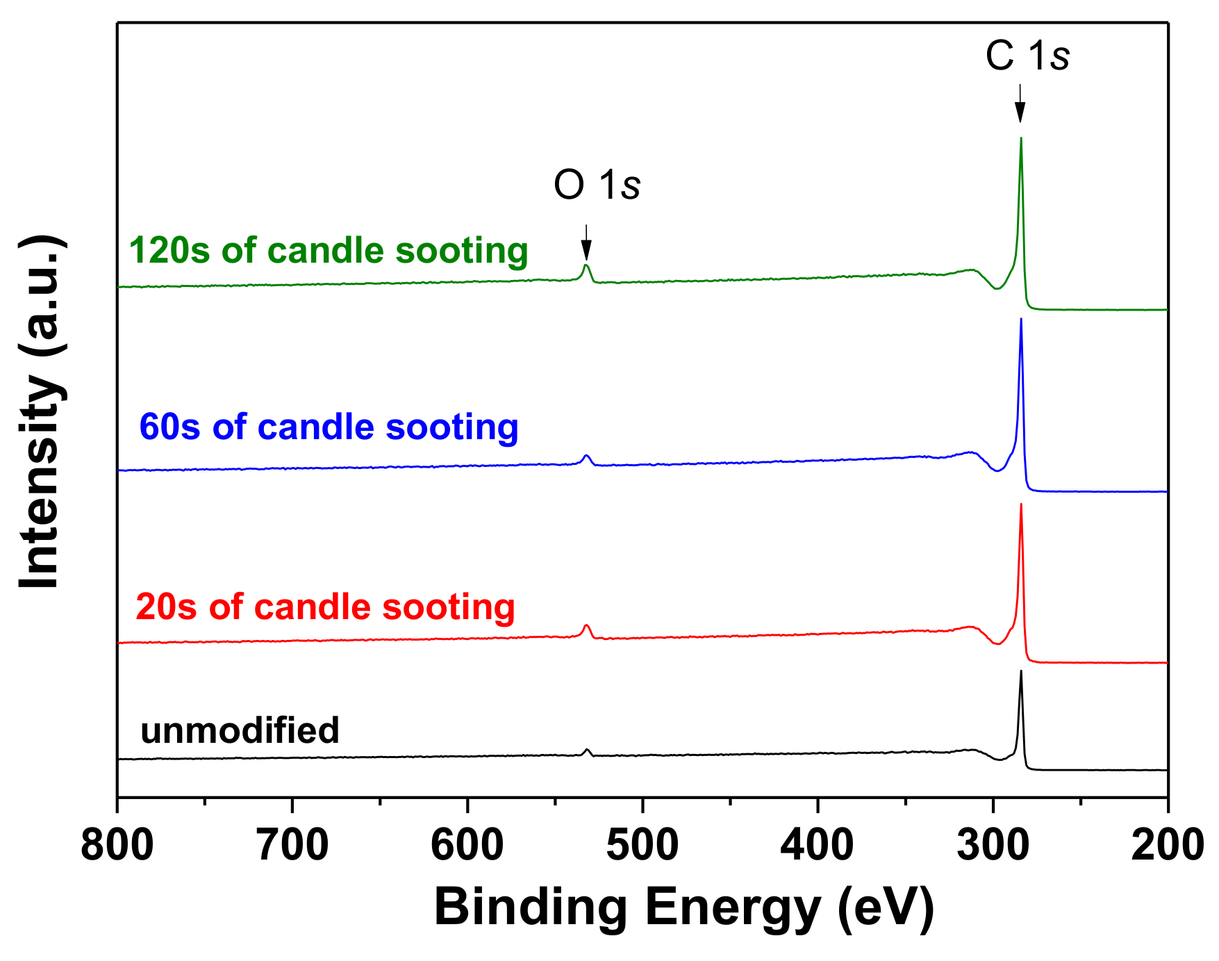
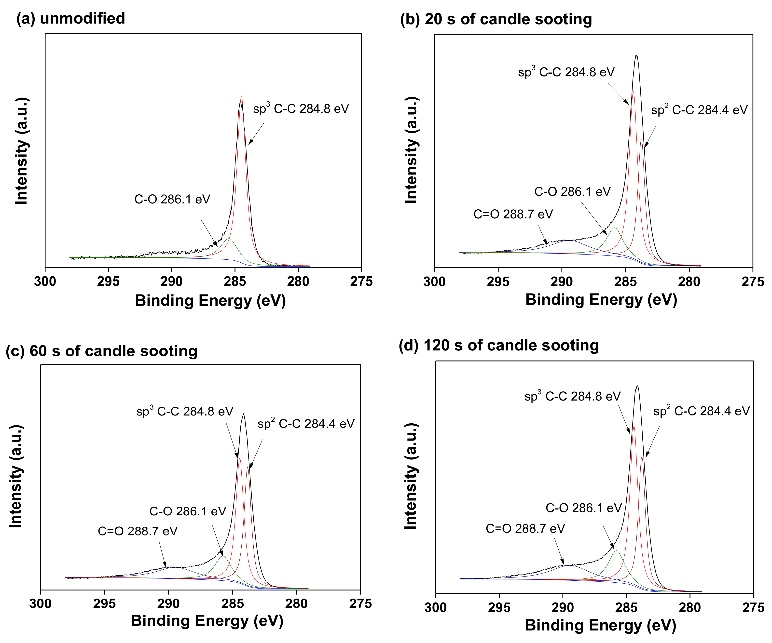
Figure 5 presents survey XPS of the unmodified and candle-soot-modified carbon cloths. Each specimen exhibited signals only at approximately 284 and 532 eV corresponding to C1s and O1s, respectively. Figure 6a–d shows C1s high-resolution XPS of the unmodified carbon cloth and those modified by 20, 60, and 120 s of candle sooting, respectively. As shown in Figure 6a, the C1s characteristic peak of the unmodified carbon cloth can be deconvoluted into a major sp3 C–C peak at approximately 284.8 eV and minor C–O peak at approximately 286.1 eV. Figure 6b reveals that the C1s characteristic peak of the 20-s candle-soot-modified carbon cloth comprises C–C and C–O peaks, as those of the unmodified carbon cloth. Additional sp2 C–C and C=O peaks appeared at approximately 284.4 and 288.7 eV, respectively. Figure 6c,d shows that the C1s characteristic peaks of the 60- and 120-s candle-soot-modified carbon cloths, respectively, were similar to that of the 20-s candle-soot-modified carbon cloth.
Figure 7a–d shows O 1s high-resolution XPS of the unmodified carbon cloth and those modified by 20, 60, and 120 s of candle sooting, respectively. As shown in Figure 7a, the signal peak for the O1s characteristic of the unmodified carbon cloth, was insignificant. The origin of the oxygen signal was likely attributed to the residual contamination on the carbon cloth surface. On the contrary, as shown in Figure 7b–d, the 20, 60, and 120-s candle-soot-modified carbon cloths exhibited significant O1s characteristic peaks, which could be distributed into C–O, C=O, and C–OH peaks at approximately 531, 532, and 533 eV, respectively. According to Figure 6 and Figure 7, it was concluded that the chemical bonding on the surface of the carbon cloth was effectively modified from major sp3 C–C and minor C–O to abundant sp2 C–C, C–O, C=O, and C–OH after the candle soot modification. Nevertheless, the candle soot residence time seemed not to significantly influence on the constitution of the chemical bonding.
3.4. Microbial Colonization
Figure 8a–d shows SEM images of the surfaces of the unmodified carbon cloth and those modified by 20, 60, and 120 s of candle sooting, respectively, after immersion in the chambers of the MFCs for 24 h. Figure 8a shows that some microorganisms colonized on the surface of the unmodified carbon cloth. In addition, some biofilm segments formed between the carbon fibers. Figure 8b–d show more abundant microorganisms and biofilms formed on the surfaces of the candle-soot-modified carbon cloths. Figure 8 demonstrates that the surface modification by candle soot could effectively accelerate the propagation of microorganisms and formation of biofilms onto the surfaces of the carbon cloths.
3.5. Electrochemical Performance
Figure 9a shows the LSV results and power density response curves of MFCs configured with the unmodified and candle-soot-modified carbon cloth electrodes. Figure 9a indicates that the highest power densities of MFCs configured with the electrode of unmodified carbon cloth and with those modified by 20, 60, and 120 s of candle sooting were ca. 10.2 ± 0.2, 13.6 ± 0.9, 19.8 ± 0.2, and 17.6 ± 0.8 mW·m−2, respectively. This implied that the power-generating efficiencies of MFCs could be effectively enhanced by the candle soot modification. To compare internal resistance figures of different MFCs, EIS analysis on MFCs configured with the unmodified and candle-soot-modified carbon cloth electrodes were implemented (Figure 9b). As shown in Figure 9b, each MFC exhibits a single capacitive loop, which was fitted by the constant-phase-element (CPE) circuit model. The circuit comprises a CPE in parallel with a charge-transfer resistance (RCT), as shown in Figure 9c; the impedance of the CPE can be calculated as: [32]. The Z-View® software (ZMANTM2.3) was adopted for fitting the impedance of the CPE; is denoted as CPE-P and T is denoted as CPE-T. Table 1 presents the calculated values of RS, CPE-T, CPE-P, and RCT of the MFCs configured with the untreated and candle-soot-modified carbon cloth electrodes. The RCT values of the MFCs configured with the unmodified carbon cloth electrode and with those modified by 20, 60, and 120 s of candle sooting were 2342, 1875, 619, and 1138 Ω, respectively. As RCT corresponds to the resistance of the electrochemical reaction on the electrode [33], Figure 9b demonstrates that the candle soot effectively improved the charge transfer efficiencies of the MFCs. The optimal duration of candle soot to minimize electron transfer resistance was ca. 60 s.
4. Discussion
According to the electrochemical results in Figure 9, evidently the MFCs configured with the candle-soot-modified carbon cloth electrodes exhibited higher power densities and lower total internal resistances than those of the MFC with the unmodified carbon cloth electrode. This was very likely attributed to the sponge-like porous structure of the deposited candle soot that effectively increased the surface areas of the electrodes and facilitated the microbial colonization (Figure 2 and Figure 8). The more promising electron transfer capabilities of modified MFCs can also be attributed to the hydrophilic surfaces of the candle-soot-modified carbon cloths. According to the XPS results in Figure 6 and Figure 7, only sp3 C–C and small number of C–O functional groups were observed on the surface of the unmodified carbon cloth, whereas abundant sp2 C–C, C–O, C=O, and C–OH functional groups were observed on the surfaces of the candle-soot-modified carbon cloths. The abundant C–O, C=O, and C–OH functional groups led to the super-hydrophilic surfaces of the candle-soot-modified carbon cloths with more electroactive characteristics for electron transfer in power generation. As bacteria were more likely to attach and propagate onto the hydrophilic surface [34], the candle-soot-modified carbon cloths would favor the microbial growth as demonstrated in Figure 5. In addition, the carboxyl functional groups on the surfaces of the candle-soot-modified carbon cloths facilitated the transfer of electrons from the attached bacteria to solid electrodes. This was possibly due to the hydrogen bonding with the membrane-bound peptide bonds in bacterial cytochromes associated with the intracellular electron transfer chain [17]. Furthermore, the conductive nature of sp2 C–C in the candle soot was beneficial to the power generation efficiencies of MFCs as the transfer of electrons from the aqueous-phase media to the solid-phase electrodes in the MFCs was not impeded by the deposited candle soot.
Although the candle-soot-modified MFCs exhibited better electrochemical characteristics than that of the unmodified MFC, the appropriate residence time of candle soot still significantly affected the electrochemical performances of the MFCs. Compared to those of the other candle-soot-modified MFCs, the MFC configured with the 20-s candle-soot-modified carbon cloth electrode exhibited the lowest power density of 13.6 ± 0.9 mW·m−2 and highest RCT of 1875 Ω. This could be attributed to the insufficient candle soot residence time, leading to a partially hydrophilic surface of the carbon cloth. On the contrary, the MFC configured with the 60-s candle-soot-modified carbon cloth electrode had the highest power density of 19.8 ± 0.2 mW·m−2 and lowest RCT of 619 Ω. This was likely attributed to the nearly complete formation of the highly hydrophilic surface of the 60-s candle-soot-modified carbon cloth. In addition, the toxicity was possibly not significantly increased after modification, thus it was more favorable for microbial colonization and biofilm formation. Although the 120-s candle-soot-modified carbon cloth exhibited comparable surface characteristics to those of the 60-s candle-soot-modified carbon cloth, the maximum power density of the MFC configured with the 120-s candle-soot-modified carbon cloth electrode (17.6 ± 0.8 mW·m−2) was slightly lower than that of the MFC configured with the 60-s candle-soot-modified carbon cloth electrode. This unexpected result could be explained by the fact that the conductivity of the candle soot film was normally deteriorated when the film was thicker than the optimal threshold thickness for maximal electron transport efficiency. That is, candle soot with coating in less layers would significantly increase hydrophilicity to reduce electron transfer resistance for power generating augmentation in MFCs. However, a dense coating of candle soot would result in increased resistance across multiple layers as an electron transfer barrier for power generation. Similar results have been obtained for other nanostructured carbonaceous or flame-soot nanoparticle films [35,36].
Extensive studies have been performed to improve the electrochemical performances of MFCs by modifying the surface properties of the anode electrodes. Table 2 lists the comparison of the chemicals and instruments used in these anode modifications [14,15,16,17,18,19,20,21,22,23,24,25,30]. As shown in Table 2, most of these techniques involve expensive instruments, complex and time-consuming processes, or potentially toxic chemicals. That was why this study intentionally used some procedure-simple and cost-effective alternatives for the surface modification of cloth electrodes with practicability. Although the power outputs achieved from the MFC with candle-soot modified electrodes are relatively low compared to the ones reported in most of the works of Table 2, this study simply focused on the applicability of using candle soot as a possible means to modify electrode characteristics for the enhancement of power generation in MFCs. Such modification was just a first-step treatability assessment and did not cover the overall optimization of the MFC system. As a matter of fact, several factors (e.g., microbial characteristics, MFC bioreactor operation strategy, biofilm development, bacterial community structure, solid-solid, solid-liquid interfacial electron-transfer resistance, exogenous electron shuttles) were inevitably still required to be explored for system optimization. However, the influences of individual factors after the modification were still worthy to be uncovered for the follow-up practicability. The carbon cloth-electrode was regularly used as control/reference to compare with our new and/or novel methods of modification and/or literature data. Recently, Singh et al. [30] were the first to deposit candle soot on ultrafine stainless steel wire disks as the anode and cathode electrodes and successfully enhanced the electrochemical properties of double-chamber MFCs. Their findings indicated that the synthesis of the carbon-nanoparticle-based electrodes by candle soot was simple, cost-effective, reproducible, and scalable, and the fabricated MFC could produce a high amount of bioenergy. In our study, we directly deposited candle soot on the surface of the carbon cloth electrode, rather than on a stainless-steel disk. Noticeably, the candle soot modification could effectively facilitate bacterial colonization and biofilm formation on the surface of the carbon cloth, increasing the extracellular electron transfer efficiency and the power generation capabilities of MFCs. However, it should be noted that the MFCs could exhibit the optimized efficiencies only when the carbon cloth was modified using an appropriate candle soot residence time for maximal electron transfer capacities to be expressed. That is, the super-hydrophilicities of the candle-soot-modified carbon cloths typically deteriorated with longer time of exposure. Therefore, the candle-soot-modified carbon cloth electrodes should be fabricated into MFCs as soon as possible after the modification is completed to exhibit an optimal performance. Besides, the candle-soot-modified carbon cloth electrodes are suitable for large-scale MFC applications because of their low cost and easily prepared. Nevertheless, the modification method for a large-scale anode should be carefully designed and controlled to obtain a homogeneous surface.
5. Conclusions
This study demonstrated that the use of candle soot is an effective and economic method for the surface modification of carbon cloth electrodes to improve the electrochemical performances of MFCs. The SEM results showed that the carbon fibers in carbon cloths were not fractured or attenuated during the candle sooting. The deposited soot particle films exhibited sponge-like structures, providing larger surface areas for bacterial adhesion. The wettability measurements revealed that a residence time of only 60 s was inevitably required to alter the hydrophobic surfaces of the carbon cloths to super-hydrophilic. XPS results showed that abundant sp2 C–C, C–O, and C=O functional groups existed on the surfaces of the candle-soot-modified carbon cloths. The C–O and C=O functional groups were responsible for the super-hydrophilicity of the non-toxic surfaces of the candle-soot-modified carbon cloths. The carboxyl and sp2 C–C functional groups favored the transfer of electrons from the attached bacteria to the electrodes. The electrochemical measurements demonstrated that the MFC configured with the 60-s candle-soot-modified carbon cloth electrode exhibited the highest power density of 19.8 ± 0.2 mW·m−2 and lowest total internal resistance of 619 Ω, among the considered MFCs. Therefore, the use of candle soot is a rapid, economic, and simple method for the surface modification of carbon cloth electrodes. However, after the candle soot modification is completed, a postponement in the MFC construction may lead to the deterioration in the super-hydrophilicity of the candle-soot-modified carbon cloth.
Author Contributions
Conceptualization, B.-Y.C.; Data Curation, Y.-T.T.; Funding Acquisition, B.-Y.C. and S.-H.C.; Investigation, B.-Y.C., Y.-T.T. and S.-H.C.; Methodology, Y.-T.T. and S.-H.C.; Project Administration, S.-H.C.; Supervision, S.-H.C.; Writing–Original Draft Preparation, S.-H.C.; Writing–Review & Editing, B.-Y.C.
Funding
This research was funded by the Ministry of Science and Technology, Taiwan (MOST 106-2221-E-197-020-MY3 and 107-2621-M-197-001 and MOST 107-2221-E197-004).
Conflicts of Interest
The authors declare no conflict of interest.
References
- Logan, B.E.; Hamelers, B.; Rozendal, R.; Schröder, U.; Keller, J.; Freguia, S.; Aelterman, P.; Verstraete, W.; Rabaey, K. Microbial fuel cells: Methodology and technology. Environ. Sci. Technol. 2006, 40, 5181–5192. [Google Scholar] [CrossRef] [PubMed]
- Pant, D.; Van Bogaert, G.; Diels, L.; Vanbroekhoven, K. A review of the substrates used in microbial fuel cells (MFCs) for sustainable energy production. Bioresour. Technol. 2010, 10, 1533–1543. [Google Scholar] [CrossRef]
- Pandey, P.; Shinde, V.N.; Deopurkar, R.L.; Kale, S.P.; Patil, S.A.; Pant, D. Recent advances in the use of different substrates in microbial fuel cells toward wastewater treatment and simultaneous energy recovery. Appl. Energy 2016, 168, 706–723. [Google Scholar] [CrossRef]
- Santoro, C.; Arbizzani, C.; Erable, B.; Ieropoulos, I. Microbial fuel cells: From fundamentals to applications. A review. J. Power Sources 2017, 356, 225–244. [Google Scholar] [CrossRef] [PubMed]
- Grattieri, M.; Minteer, S.D. Self-Powered Biosensors. ACS Sens. 2018, 3, 44–53. [Google Scholar] [CrossRef]
- Logan, B.E.; Regab, J.M. Microbial fuel cells—Challenges and applications. Environ. Sci. Technol. 2006, 40, 5172–5180. [Google Scholar] [CrossRef] [PubMed]
- Li, W.W.; Yu, H.Q.; He, Z. Towards sustainable wastewater treatment by using microbial fuel cells-centered technologies. Energy Environ. Sci. 2014, 911–924. [Google Scholar] [CrossRef]
- Yu, F.; Wang, C.; Ma, J. Applications of graphene-modified electrodes in microbial fuel cells. Materials 2016, 9, 807. [Google Scholar] [CrossRef]
- Chaudhuri, S.K.; Lovely, D.R. Electricity generation by direct oxidation of glucose in mediator less microbial fuel cells. Nat. Biotechnol. 2003, 21, 1229–1232. [Google Scholar] [CrossRef]
- Park, D.H.; Zeikus, J.G. Improved fuel cell and electrode designs for producing electricity from microbial degradation. Biotechnol. Bioeng. 2003, 81, 348–355. [Google Scholar] [CrossRef]
- Ishii, S.; Watanabe, K.; Yabuki, S.; Logan, B.E.; Sekiguchi, Y. Comparison of electrode reduction activities of geobacter sulfurreducens and an enriched consortium in an air-cathode microbial fuel cell. Appl. Environ. Microbiol. 2008, 74, 7348–7355. [Google Scholar] [CrossRef] [PubMed]
- Wei, J.; Huang, X. Recent progress in electrodes for microbial fuel cell. Bioresour. Technol. 2011, 102, 9335–9344. [Google Scholar] [CrossRef] [PubMed]
- Kalathil, S.; Pant, D. Nanotechnology to rescue bacterial bidirectional extracellular electron transfer in bioelectrochemical systems. RSC Adv. 2016, 6, 30582–30597. [Google Scholar] [CrossRef] [Green Version]
- Cheng, S.A.; Logan, B.E. Ammonia treatment of carbon cloth anodes to enhance power generation of microbial fuel cells. Electrochem. Commun. 2007, 9, 492–496. [Google Scholar] [CrossRef]
- Feng, Y.; Yang, Q.; Wang, X.; Logan, B.E. Treatment of carbon fiber brush anodes for improving power generation in air–cathode microbial fuel cells. J. Power Sources 2010, 195, 1841–1844. [Google Scholar] [CrossRef]
- Lowy, D.A.; Tender, L.M. Harvesting energy from the marine sediment-water interface III—Kinetic activity of quinone- and antimony-based anode materials. J. Power Sources 2008, 185, 70–75. [Google Scholar] [CrossRef]
- Tang, X.; Guo, K.; Li, H.; Du, Z.; Tian, J. Electrochemical treatment of graphite to enhance electron transfer from bacteria to electrodes. Bioresour. Technol. 2011, 102, 3558–3560. [Google Scholar] [CrossRef]
- Chang, S.H.; Liou, J.S.; Liu, J.L.; Chiu, Y.F.; Xu, C.H.; Chen, B.Y.; Chen, J.Z. Feasibility study of surface-modified carbon cloth electrodes using atmospheric pressure plasma jets for microbial fuel cells. J. Power Sources 2016, 336, 99–106. [Google Scholar] [CrossRef]
- Tsai, H.Y.; Wu, C.C.; Lee, C.Y.; Shih, E.P. Microbial fuel cell performance of multiwall carbon nanotubes on carbon cloth as electrodes. J. Power Sources 2009, 194, 199–205. [Google Scholar] [CrossRef]
- Kim, J.R.; Min, B.; Logan, B.E. Evaluation of procedures to acclimate a microbial fuel cell for electricity production. Appl. Microbiol. Biotechnol. 2005, 68, 23–30. [Google Scholar] [CrossRef]
- Alatraktchi, F.A.; Zhang, Y.; Angelidaki, I. Nanomodification of the electrodes in microbial fuel cell: Impact of nanoparticle density on electricity production and microbial community. Appl. Energy 2014, 116, 216–222. [Google Scholar] [CrossRef]
- Wang, L.; Su, L.; Chen, H.; Yin, T.; Lin, Z.; Lin, X.; Yuan, C.; Fu, D. Carbon paper electrode modified by goethite nanowhiskers promotes bacterial extracellular electron transfer. Mater. Lett. 2015, 141, 311–314. [Google Scholar] [CrossRef]
- Qiao, Y.; Wu, X.S.; Li, C.M. Interfacial electron transfer of Shewanella putrefaciens enhanced by nanoflaky nickel oxide array in microbial fuel cells. J. Power Sources 2014, 266, 226–231. [Google Scholar] [CrossRef]
- Chang, S.H.; Huang, B.Y.; Wan, T.H.; Chen, J.Z.; Chen, B.Y. Surface modification of carbon cloth anodes for microbial fuel cells using atmospheric-pressure plasma jet processed reduced graphene oxides. RSC Adv. 2017, 7, 56433–56439. [Google Scholar] [CrossRef] [Green Version]
- Rosenbaum, M.; Zhao, F.; Quaas, M.; Wulff, H.; Schröder, U.; Scholz, F. Evaluation of catalytic properties of tungsten carbide for the anode of microbial fuel cells. Appl. Catal. B 2007, 74, 261–269. [Google Scholar] [CrossRef]
- Wei, Z.; Yan, K.; Chen, H.; Yi, Y.; Zhang, T.; Long, X.; Li, J.; Zhang, L.; Wang, J.; Yang, S. Cost-efficient clamping solar cells using candle soot for hole extraction from ambipolar perovskites. Energ. Environ. Sci. 2014, 7, 3326–3333. [Google Scholar] [CrossRef]
- Kakunuri, M.; Sharma, C.S. Candle soot derived fractal-like carbon nanoparticles network as high-rate lithium ion battery anode material. Electrochim. Acta 2015, 180, 353–359. [Google Scholar] [CrossRef]
- Khalakhan, I.; Fiala, R.; Lavková, J.; Kúš, P.; Ostroverkh, A.; Václavů, M.; Vorokhta, M.; Matolínová, I.; Matolín, V. Candle soot as efficient support for proton exchange membrane fuel cell catalyst. Fuel Cells 2016, 16, 652–655. [Google Scholar] [CrossRef]
- Liang, C.J.; Liao, J.D.; Li, A.J.; Chen, C.; Lin, H.Y.; Wang, X.J.; Xu, Y.H. Relationship between wettabilities and chemical compositions of candle soots. Fuel 2014, 128, 422–427. [Google Scholar] [CrossRef]
- Singh, S.; Bairagi, P.K.; Verma, N. Candle soot-derived carbon nanoparticles: An inexpensive and efficient electrode for microbial fuel cells. Electrochim. Acta 2018, 264, 119–127. [Google Scholar] [CrossRef]
- Chen, B.Y.; Zhang, M.M.; Chang, C.T.; Ding, Y.; Lin, K.L.; Chiou, C.S.; Hsueh, C.C.; Xu, H. Assessment upon azo dye decolorization and bioelectricity generation by Proteus hauseri. Bioresour. Technol. 2010, 101, 4737–4741. [Google Scholar] [CrossRef] [PubMed]
- Jorcin, J.B.; Orazem, M.E.; Pebere, N.; Tribollet, B. CPE analysis by local electrochemical impedance spectroscopy. Electrochim. Acta 2006, 51, 1473–1479. [Google Scholar] [CrossRef] [Green Version]
- Qiao, Y.; Li, C.M.; Bao, S.J.; Bao, Q.L. Carbon nanotube/polyaniline composite as anode material for microbial fuel cells. J. Power Sources 2007, 170, 790–794. [Google Scholar] [CrossRef]
- Han, T.H.; Sawant, S.Y.; Hwang, S.J.; Cho, M.H. Three-dimensional, highly porous N-doped carbon foam as microorganism propitious, efficient anode for high performance microbial fuel cell. RSC Adv. 2016, 6, 25799–25807. [Google Scholar] [CrossRef]
- Bruzzi, M.; Piseri, P.; Miglio, S.; Bongiorno, G.; Barborini, E.; Ducati, C.; Robertson, J.; Milani, P. Electrical conduction in nanostructured carbon and carbon-metal films grown by supersonic cluster beam deposition. Eur. Phys. J. B 2003, 36, 3–13. [Google Scholar] [CrossRef]
- De Falco, G.; Commodo, M.; Barra, M.; Chiarella, F.; D’Anna, A.; Aloisio, A.; Cassinese, A.; Minutolo, P. Electrical characterization of flame-soot nanoparticle thin films. Synth. Met. 2017, 229, 89–99. [Google Scholar] [CrossRef]
Figure 1.
Photography of the membrane-free air-breathing cathode single-chamber microbial fuel cells (MFC).
Figure 1.
Photography of the membrane-free air-breathing cathode single-chamber microbial fuel cells (MFC).

Figure 2.
Top-view SEM images of the (a) unmodified carbon cloth and those modified by candle sooting for (b) 20 s, (c) 60 s, and (d) 120 s. (e,f) Magnified views of (c) and (d), respectively.
Figure 2.
Top-view SEM images of the (a) unmodified carbon cloth and those modified by candle sooting for (b) 20 s, (c) 60 s, and (d) 120 s. (e,f) Magnified views of (c) and (d), respectively.

Figure 3.
Cross-sectional SEM images of the (a) unmodified carbon cloth and those modified by candle sooting for (b) 20 s, (c) 60 s, and (d) 120 s.
Figure 3.
Cross-sectional SEM images of the (a) unmodified carbon cloth and those modified by candle sooting for (b) 20 s, (c) 60 s, and (d) 120 s.


Figure 4.
(a) Water contact angles of the unmodified carbon cloth and those modified by candle sooting for 20, 60, and 120 s. (b) Water contact angles of the unmodified and candle-soot-modified carbon cloths as a function of the standing time.
Figure 4.
(a) Water contact angles of the unmodified carbon cloth and those modified by candle sooting for 20, 60, and 120 s. (b) Water contact angles of the unmodified and candle-soot-modified carbon cloths as a function of the standing time.

Figure 5.
Survey XPS of the unmodified and candle-soot-modified carbon cloths.

Figure 6.
C 1s XPS of the surfaces of the (a) unmodified carbon cloth and those modified by candle sooting for (b) 20 s, (c) 60 s, and (d) 120 s.
Figure 6.
C 1s XPS of the surfaces of the (a) unmodified carbon cloth and those modified by candle sooting for (b) 20 s, (c) 60 s, and (d) 120 s.

Figure 7.
O1s XPS of the surfaces of the (a) unmodified carbon cloth and those modified by candle sooting for (b) 20 s, (c) 60 s, and (d) 120 s.
Figure 7.
O1s XPS of the surfaces of the (a) unmodified carbon cloth and those modified by candle sooting for (b) 20 s, (c) 60 s, and (d) 120 s.

Figure 8.
SEM images of the surfaces of the (a) unmodified carbon cloth and those modified by (b) 20, (c) 60, and (d) 120 s of candle sooting after immersion in the chambers of the MFCs for 24 h.
Figure 8.
SEM images of the surfaces of the (a) unmodified carbon cloth and those modified by (b) 20, (c) 60, and (d) 120 s of candle sooting after immersion in the chambers of the MFCs for 24 h.

Figure 9.
(a) Power density response curves and (b) EIS results of the MFCs configured with the unmodified and candle-soot-modified carbon cloths; (c) Equivalent circuit model.
Figure 9.
(a) Power density response curves and (b) EIS results of the MFCs configured with the unmodified and candle-soot-modified carbon cloths; (c) Equivalent circuit model.


Table 1.
RS, CPE-T, CPE-P, and RCT of the MFCs configured with the unmodified and 20-, 60-, and 120-s candle-soot-modified carbon cloth electrodes.
Table 1.
RS, CPE-T, CPE-P, and RCT of the MFCs configured with the unmodified and 20-, 60-, and 120-s candle-soot-modified carbon cloth electrodes.
| Modified Sample | RS (Ω) | CPE-T | CPE-P | RCT (Ω) |
|---|---|---|---|---|
| unmodified | 27.21 | 0.0075 | 0.7985 | 2342 |
| 20 s of candle sooting | 25.73 | 0.0054 | 0.6458 | 1875 |
| 60 s of candle sooting | 22.06 | 0.0091 | 0.6665 | 619 |
| 120 s of candle sooting | 20.82 | 0.0070 | 0.7580 | 1138 |
Table 2.
Comparison of the chemicals and instruments used in various anode modifications.
| Methods | Anode Materials | Chemicals and Instruments Used in Modifications | Performance | Ref. |
|---|---|---|---|---|
| NH3 gas treatment | Carbon cloth | Ammonia | Maximum power density of 1970 mW·m−2 | [14] |
| Acid soaking and heating | Carbon fiber brush | Ammonium Peroxydisulfate, Concentrated Sulfuric Acid, Muffle Furnace | Maximum power density of 1370 mW·m−2 | [15] |
| Oxidized anode and modified by AQDS | Graphite plate | Anthraquinone-1,6-disulfonic Acid, Perchloric Acid, 1,4-Naphthoquinone, Ethanol | Increase kinetic activity of a factor of 218 | [16] |
| Electrochemical treatment for 12 h | Graphite felt | H2SO4 | Increase current production of 39.5% | [17] |
| Atmospheric pressure plasma jets | Carbon cloth | Atmospheric Pressure Plasma Jets | Increase maximum power density from 2.38 to 7.56 mW·m−2 | [18] |
| Coating carbon nanotube | Carbon cloth | Multiwall Carbon Nanotubes, Ethanol | Maximum power density of 65 mW·m−2 | [19] |
| Coating Ferric Oxide | Carbon paper | Ferric Citrate, Acetate | Increase maximum power density from 2 to 40 mW·m−2 | [20] |
| Sputtering Au nanoparticles | Carbon paper | Au Nanoparticles, Electron Beam Physical Vapor Deposition (EBPVD) Machine | 1.22–1.88-Fold increase in power density | [21] |
| Coating goethite nanowhiskers | Carbon paper | Fe(NO3)3·9H2O, Teflon-lined Stainless Steel Autoclave, KOH | 60% increase in current density | [22] |
| Coating NiO nanoflaky array | Carbon cloth | H2SO4, Nickel Chloride, CO(NH2)2, Hexadecyl Trimethyl Ammonium Bromide, Teflon-lined Stainless Steel Autoclave | 3-Fold increase in power density | [23] |
| Atmospheric-pressure plasma jet processed reduced graphene oxides | Carbon cloth | Atmospheric Pressure Plasma Jets, Reduced Graphene Oxide, Terpineol, Ethanol, Ethyl Cellulose | Increase maximum power density from 6.02 to 10.80 mW·m−2 | [24] |
| Tungsten carbide | Graphite foil | Tungsten Carbide, Yellow Tungsten Acid, Oxalic Acid, NH4Cl, Tube Furnace | Achieve current density of 8.8 mA·m−2 | [25] |
| Coating candle soot on ultrafine stainless steel wire disks | Ultrafine stainless steel wire disk | HCl, Acetone, Ethanol, Candle, Hydraulic Press | Produced a high OCP (0.68 V), limiting current density (7135 mA/m2) and power generation (1650 mW/m2) | [30] |
| Coating candle soot on carbon cloths | Carbon cloth | Candle | Increase maximum power density from 10.2 to 19.8 mW·m−2 | This study |
© 2018 by the authors. Licensee MDPI, Basel, Switzerland. This article is an open access article distributed under the terms and conditions of the Creative Commons Attribution (CC BY) license (http://creativecommons.org/licenses/by/4.0/).
Share and Cite
MDPI and ACS Style
Chen, B.-Y.; Tsao, Y.-T.; Chang, S.-H. Cost-Effective Surface Modification of Carbon Cloth Electrodes for Microbial Fuel Cells by Candle Soot Coating. Coatings 2018, 8, 468. https://doi.org/10.3390/coatings8120468
AMA Style
Chen B-Y, Tsao Y-T, Chang S-H. Cost-Effective Surface Modification of Carbon Cloth Electrodes for Microbial Fuel Cells by Candle Soot Coating. Coatings. 2018; 8(12):468. https://doi.org/10.3390/coatings8120468
Chicago/Turabian StyleChen, Bor-Yann, Yuan-Ting Tsao, and Shih-Hang Chang. 2018. "Cost-Effective Surface Modification of Carbon Cloth Electrodes for Microbial Fuel Cells by Candle Soot Coating" Coatings 8, no. 12: 468. https://doi.org/10.3390/coatings8120468
Note that from the first issue of 2016, this journal uses article numbers instead of page numbers. See further details here.