

Computer Simulation of Phase Transitions in Thin Films with an Antidote Lattice

1
Department of Physics, Omsk State Technical University, 644050 Omsk, Russia
2
Department of Radiophysics and Electronics, Chelyabinsk State University, 454001 Chelyabinsk, Russia
*
Author to whom correspondence should be addressed.
Coatings 2022, 12(10), 1526; https://doi.org/10.3390/coatings12101526
Submission received: 3 September 2022
/
Revised: 5 October 2022
/
Accepted: 11 October 2022
/
Published: 12 October 2022
(This article belongs to the Section Corrosion, Wear and Erosion)
Abstract
:We investigate the magnetic phase transition in a thin film with an antidote lattice by computer simulation. A lattice of non-magnetic antidotes is present in a thin film of several atomic layers. The antidotes form a rectangular lattice. We are looking at two forms of antidotes. The Ising model and Wolf’ cluster algorithm simulate the system’s magnetic behavior. Antidotes act on additional surfaces of the system. This results in a change in the Curie temperature of the system. Dependence of phase transition temperature on holes size and shape is obtained. The phase transition temperature depends on the size of the hole by logarithmic law. The Curie temperature for triangular holes is lower than for square holes. We investigated the magnetization of a thin film with an antidote lattice and constructed a hysteresis loop. The hysteresis loop expands as the hole size decreases. Coercive force depends on the size and shape of the holes. Coercive force varies by nonlinear law.
1. Introduction
Ferromagnetic antidote structures are continuous films with a periodic lattice of holes [1,2]. This peculiarity changes the magnetic properties of materials. Thin film materials with controlled parameters are important in the creation of spintronic devices. Magnetic films with antidotes are promising materials for the creation of new generation magnetic transistors [3,4,5]. Magnetic recording media are created on their basis [6]. Antidotes increase the inner surface of materials. The result of the surface increase is a variation in the optical [7,8], electrical [9,10] and magnetic [11] properties of the film. Several approaches for producing film with antidotes currently exist: electron beam lithography [12,13], focal ion milling [14] and self-assembly of nanoscale spheres [7,15,16]. These methods control the size of antidotes, their relative position and the distance between them.
A lattice of non-magnetic holes creates a demagnetization field. This field affects the movement of the magnetic domain walls. Walls of magnetic domains are fixed on antidotes, leading to an increase in coercive force [17,18,19,20]. Antidote lattice affects magnetic resistance, magnetic permeability and magnetic anisotropy of the film [11,21,22,23,24,25,26,27]. The presence of holes slows down the magnetic relaxation process [28,29,30,31]. The presence of triangular antidotes increases the relaxation time by nine times compared to relaxation of continuous film. Magnetic domains are bound be the edges of the antidotes. Magnetization takes longer to reverse. Micromagnetic simulations in combination with X-ray microscopy showed that for small antidote sizes, the dominant contribution yields an exchange interaction [32].
Experimental methods investigate thin films with antidotes lattice based on different materials. Experimental studies for the spin dynamics in NiFe thin film with an antidote lattice on a silicone substrate demonstrated the dependence of the magnetic properties in the system on the size and mutual location of holes [33]. Fe, Co and Permalloy (Py) films with antidotes are created using nanospheric lithography [34]. Studies of magnetization of these films demonstrate an increase in hysteresis loop width with an increase in the linear dimensions of antidotes and the distance between them. Coercive force grows by linear law. Changing the size of the holes and the distance between them in the Co film creates a coercive force with a given value [35]. Hole sizes vary from 20 nm to 60 nm. The hysteresis loop changes shape as the hole sizes and the distances between them increase. The dependence of coercive force on the external magnetic field is close to linear. The square antidotes lattice in thin films Fe, Ni and NiFe makes it possible to investigate the dependence of coercive force on its parameters and film material [36]. Coercive force changes by nonlinear law as the linear dimensions of the holes in these experiments increase. Studies of the antidote lattice in the Co film using electron scanning spectroscopy revealed a dependence of magnetic properties on the lattice’s symmetry [25,37]. The properties of the film depend on the shape, mutual location and dimensions of the holes, as well as the distance between them.
The purpose of this article is to simulate phase transitions in thin films with an antidote array.
2. Model
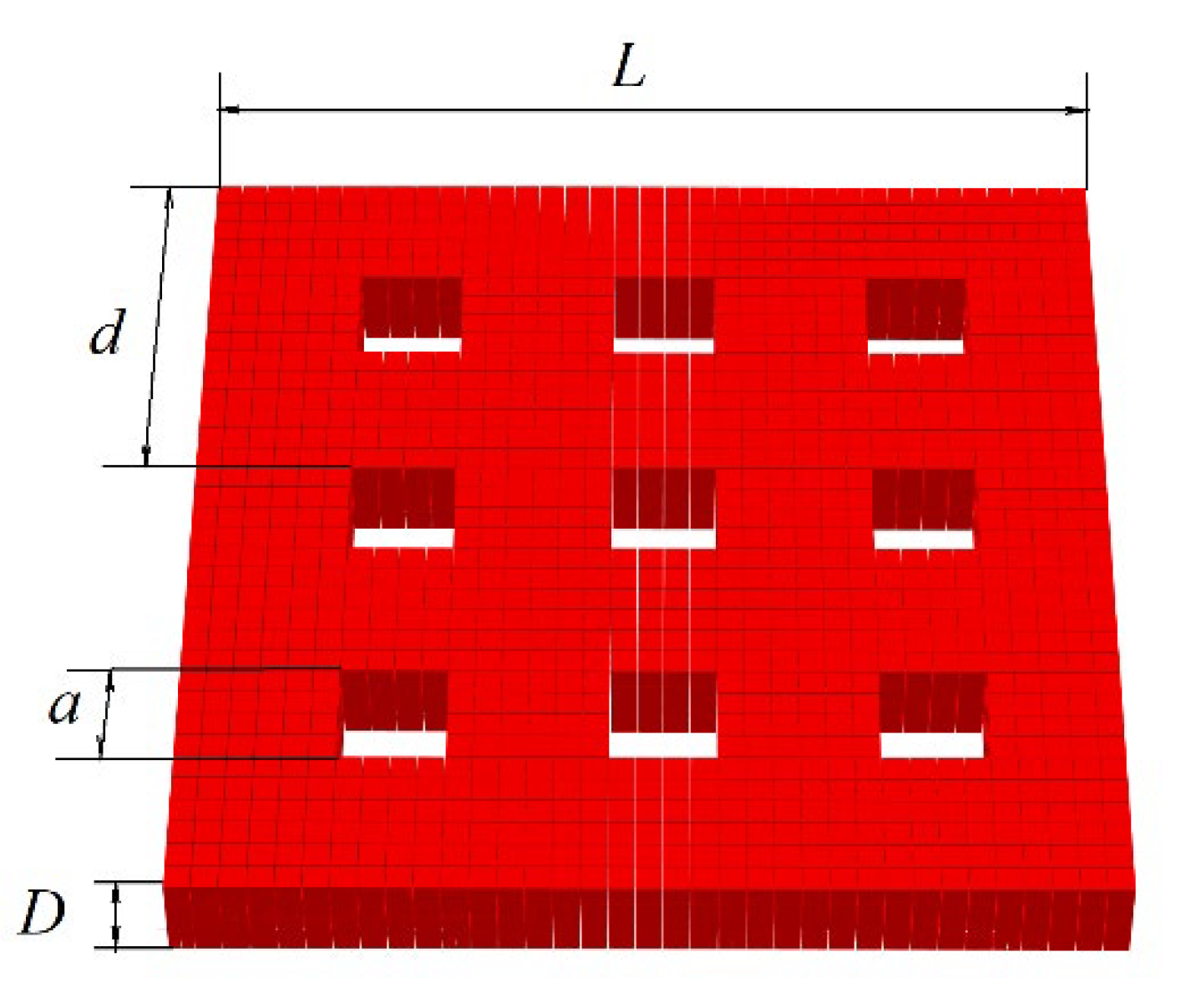
We consider a two-dimensional film with a thickness of D atomic layer. The antidote lattice is implemented as square-shaped holes. Holes are located in nodes of the square grid with period . The side of the hole square equal . The geometry of the system is shown in Figure 1.
We use the Ising model to study the magnetic properties of the system. Each film atom has a spin . Spin projection can take one of two values (1/2 or −1/2). We consider a simple ferromagnetic material with an exchange interaction. The exchange integral is . The Hamiltonian is equal to the sum of the pairwise spins’ interactions for such system.
Spins and in the first term are the spins of nearest neighbors. The second term describes the interaction with the external magnetic field. is a Bohr magneton, and is an external magnetic field. The second term contains the calculation of the sum of all the system spins.
It is more convenient to use relative values in computer modeling. The reduced temperature is used instead of the actual temperature .
Similarly, the reduced magnetic field strength is used in the calculations instead of the actual external magnetic field strength .
The Hamiltonian has been rewritten in given values.
We use the sum of spin projections to determine magnetization.
is the total number of spins in the system. Magnetization is an order parameter at ferromagnetic phase transition.
The system is located between the and planes. Periodic boundary conditions are applied to the system along the OX and OY axes. We use the Wolf’s cluster algorithm [38] to model a system near the Curie point.
Fourth-order Binder cumulants [39] make it possible to determine the Curie temperature of the system.
Cumulants use a thermodynamic average over different system configurations. Angle brackets mean a thermodynamic averaging operation. The main property of fourth-order Binder cumulants is that their values are independent of the simulated system dimensions at the phase transition point. Systems with different linear size are simulated. The dependence of on temperature is constructed for each system. All of these plots intersect at one point. This point corresponds to the Curie temperature for the system.
Critical phenomena are present in the system near the Curie point. These phenomena lead to singular behavior of thermodynamic functions. Power functions approximate the dependence of thermodynamic parameters on temperature. Exponents of such functions are called critical exponents. The critical exponential describes the behavior of magnetization.
The critical exponential describes the behavior of magnetic susceptibility.
The critical exponential describes the growth of the correlation radius .
Magnetic susceptibility is calculated based on thermodynamic magnetization averages.
Finite-dimensional scaling theory [40] expresses these quantities through the size of the system .
We model systems with different linear size and calculate the ratio of the critical exponents and .
We use the Metropolis algorithm to build a hysteresis loop [41]. Wolf’s cluster algorithm significantly speeds up calculations when determining phase transition parameters. But this algorithm erases all information about the previous state of the system. This property does not allow it to be used in the study of system magnetization.
3. Phase Transition
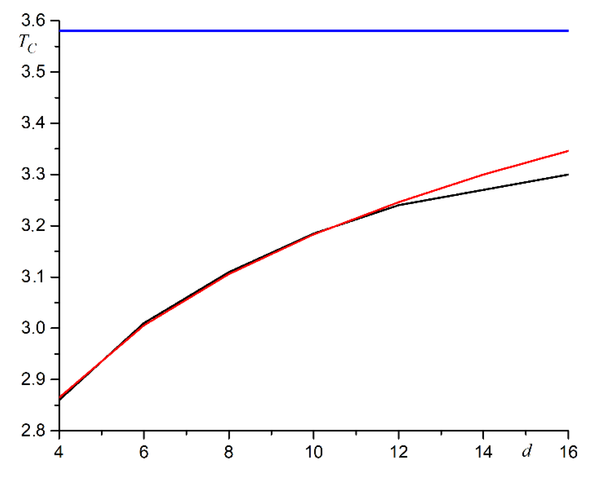
In the first computer experiment, we examine systems with hole sizes equal to half the period of grid (). Hole size increases as antidote lattice period increases. The period varies from to in increments . The linear dimensions of the system include an integer number of periods. This requirement is a consequence of periodic boundary conditions. We use systems with linear dimensions from to in increments . The film thickness is four atomic layers (). A plot of Curie temperature versus lattice period is shown in Figure 2.
As can be seen from Figure 2, the logarithmic function approximates the Curie temperature versus antidote lattice period at .
The phase transition temperature approaches the Curie point for the continuous film () as the period increases. Deviation from logarithmic dependence and transition to asymptotic value T0 occurs at period of antidote lattice . This behavior is associated with a change in the inner surface of the film by one spin. The inner surface area for the film is equal to the total number of spins on the surfaces of the individual holes.
We calculate the number of spins in a film with holes .
The inner surface per spin is equal to the ratio of these values.
The inner surface decreases by one spin as the antidote lattice period increases. The antidote lattice film tends to be a continuous film in its properties.
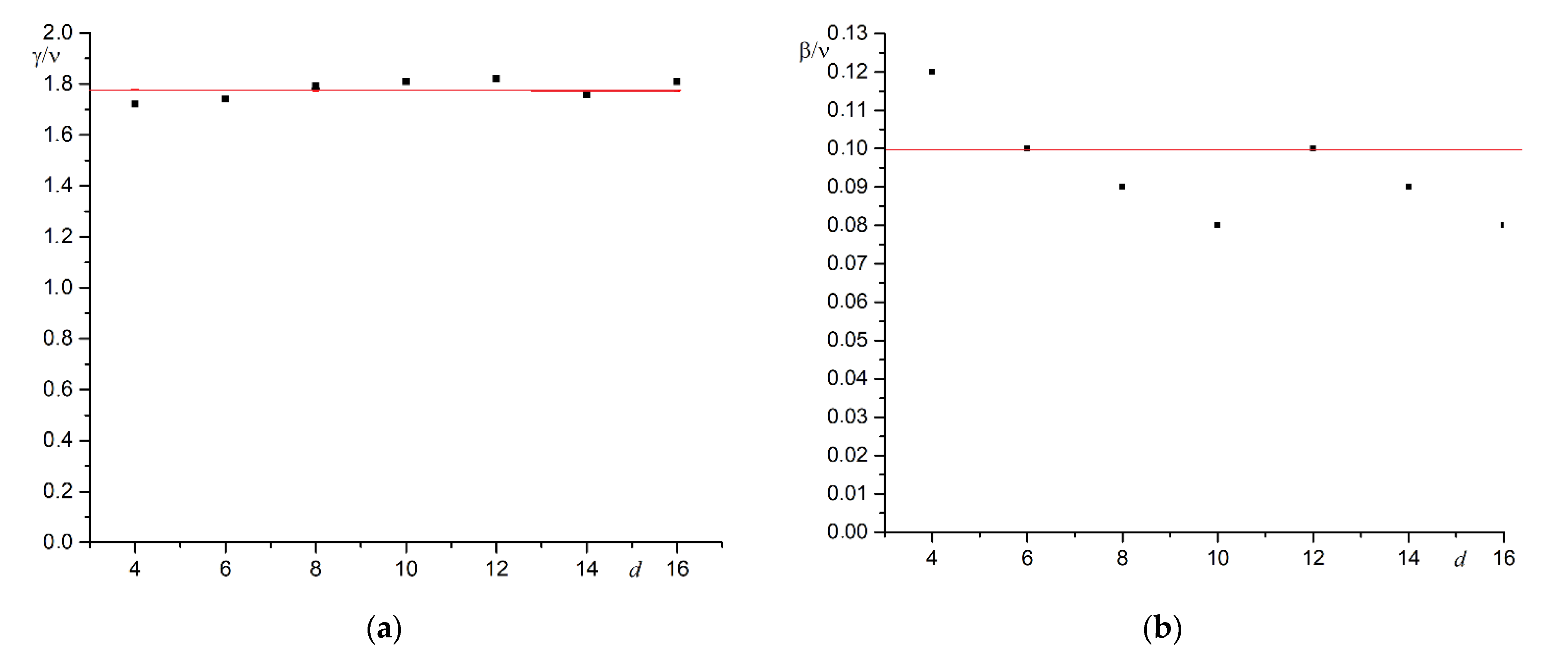
The dependence of the critical exponents’ ratio and on the antidotes lattice period is shown in Figure 3.
Critical exponents are independent of the antidote’s presence. The ratios of critical exponents for a continuous film with thickness are and . Critical exponents for antidote lattice film are and . These values match with the errors.
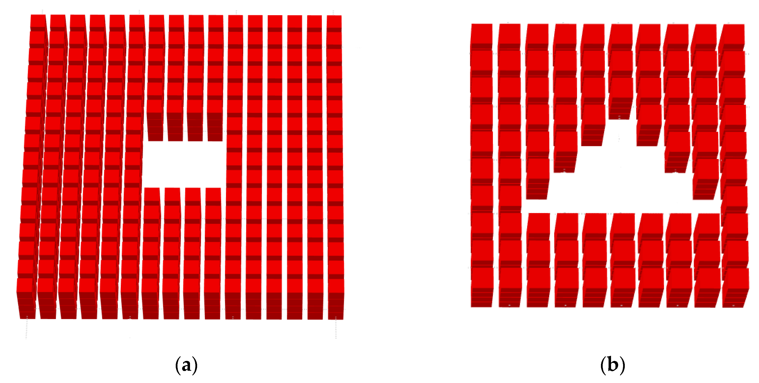
We investigated the dependence of the magnetic properties of the system on the distance between the holes and the holes shape in a second computer experiment. Two holes shapes were present in the second experiment. The first lattice contains square holes with constant side . The second lattice contains triangular holes. The base of the triangle is . The height of the triangle is . Both types of holes exclude 16 spins from the lattice. The hole areas can be considered the same and equal to 16. The shape of the holes is shown in Figure 4.
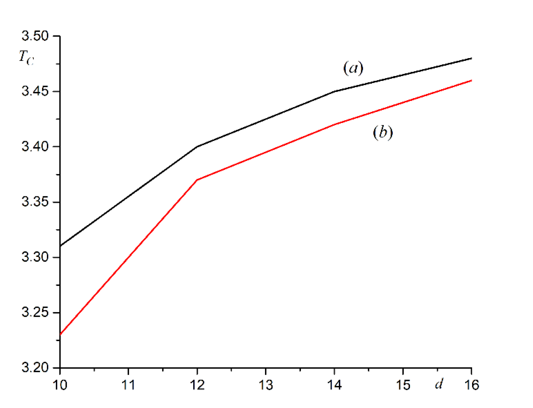
This computer experiment demonstrates the dependence of magnetic properties only on the shape of the holes, but not on their size. The antidote lattice period varied from to in steps . Curie temperature versus antidote lattice period is shown in Figure 5.
The graphs in Figure 5 show the dependence of Curie temperature on the hole’s shape. The triangular antidote lattice has a lower phase transition temperature. The Curie temperature for systems with a constant hole size is rising faster than for systems with increasing holes. This is due to a faster decrease in the area of the inner surface on the spin.
The logarithmic law does not hold in this case. Critical exponents for these systems also coincide with values for thin film.
4. Hysteresis Loop
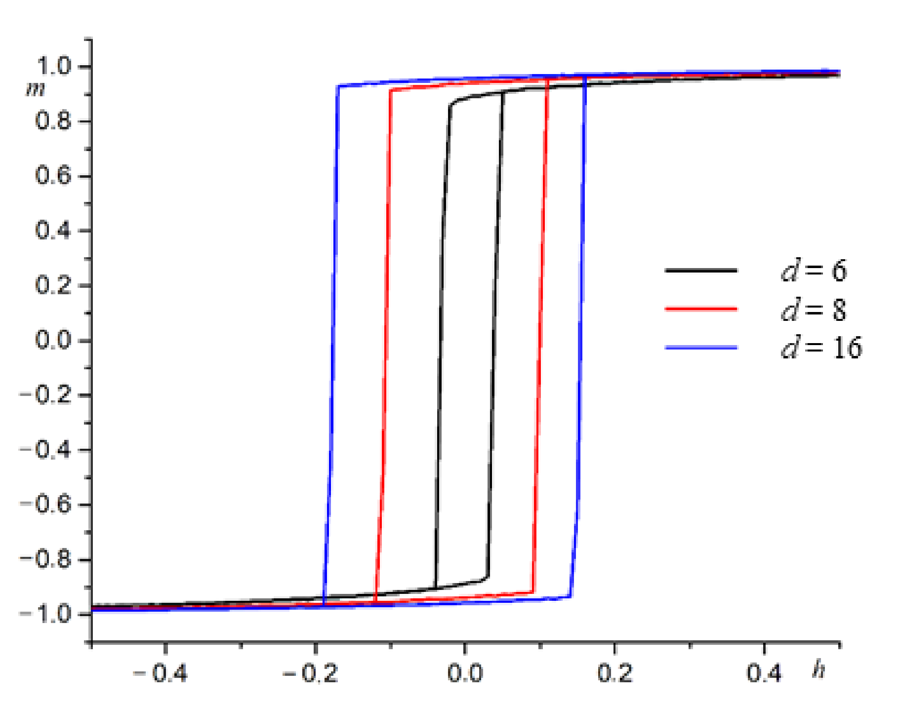
We investigate the process of magnetizing thin films with an antidote lattice. The holes have a constant size. The film thickness is . Square holes have side . The antidote lattice period varies from to . The linear size of the film is proportional to the whole number of periods for performing periodic boundary conditions. We are investigating systems with linear size . The film temperature is . This temperature provides a ferromagnetic phase for films with any antidote lattice period. Magnetic field varies from to with pitch . An example of hysteresis loops for antidote lattices with different periods is shown in Figure 6.
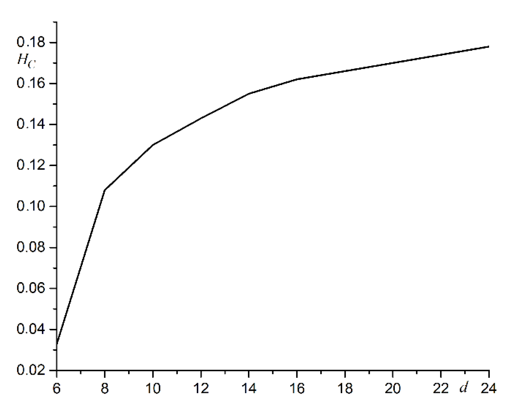
The hysteresis loop width increases as the antidote lattice period increases. This dependence is due to the reduction of the free surface by one spin. The average number of neighbors in one spin decreases as the free surface decreases. This complicates the process of changing the spin direction. Coercive force increases as a result of this. The dependence of coercive force on the antidote lattice period is shown in Figure 7.
Coercive force grows nonlinearly with increasing antidote lattice period. The coercive force value tends to a limit value for a solid thin film as the period of the antidote lattice grows.
5. Conclusions
We investigated thin films with antidote lattice by computer simulation. The results demonstrate agreement with the experimental data. The magnetic properties of the system depend on the hole’s shape and dimensions. The lattice period has a strong effect on Curie temperature. The main factor affecting the magnetic properties of the antidote lattice film is the free surface area. The hole’s shape changes the Curie temperature of the system. If the hole’s dimension increases in proportion to the antidote lattice period, then the phase transition temperature increases according to the logarithmic law. If the hole’s dimension remains constant, the increase in the phase transition temperature is faster. The Curie temperature tends to a value for a continuous film in all cases. Critical exponents are independent of the antidote lattice. Their values coincide with the critical exponents for the continuous film.
Author Contributions
Conceptualization, S.V.B.; funding acquisition, I.V.B.; investigation, S.V.B., I.V.T. and S.S.B.; methodology, I.V.B. and S.V.B.; project administration, I.V.B.; software, I.V.T., S.S.B.; writing—original draft, S.V.B. and S.S.B. All authors have read and agreed to the published version of the manuscript.
Funding
This research was funded by Russian Science Foundation, project No. 22-19-00355.
Institutional Review Board Statement
Not applicable.
Informed Consent Statement
Not applicable.
Data Availability Statement
Not applicable.
Conflicts of Interest
The authors declare no conflict of interest.
References
- Martyanov, O.N.; Yudanov, V.F.; Lee, R.N.; Nepijko, S.A.; Elmers, H.J.; Hertel, R.; Schneider, C.M.; Schönhense, G. Ferromagnetic resonance study of thin film antidot arrays: Experiment and micromagnetic Simulations. Phys. Rev. B 2007, 75, 174429. [Google Scholar] [CrossRef] [Green Version]
- Vázquez, M.; Pirota, K.R.; Navas, D.; Asenjo, A.; Hernández-Vélez, M.; Prieto, P.; Sanz, J.M. Ordered magnetic nanohole and antidot arrays prepared through replication from anodic alumina templates. J. Magn. Magn. Mater. 2008, 320, 1978–1983. [Google Scholar] [CrossRef]
- Moore, L.; Goldhaber-Gordon, D. Magnetic lattice surprise. Nat. Phys. 2007, 3, 295–296. [Google Scholar] [CrossRef]
- Beroulle, V.; Bertrand, I.; Latorre, L.; Nouet, P. Monolithic piezoresistive CMOS magnetic field sensors. Sens. Actuators A Phys. 2003, 103, 23–32. [Google Scholar] [CrossRef]
- Seemann, K.; Leiste, H.; Ziebert, C. Soft magnetic FeCoTaN film cores for new high-frequency CMOS compatible micro-inductors. J. Magn. Magn. Mater. 2007, 316, e879–e882. [Google Scholar] [CrossRef]
- Leitao, D.C.; Ventura, J.; Pereira, A.M.; Sousa, C.T.; Morira, J.M.; Carpinteiro, F.C.; Sousa, J.B.; Vazquez, M.; Araujo, J.P. Study of Nanostructured Array of Antidots Using Pulsed Magnetic Fields. J. Low Temp. Phys. 2010, 159, 245–248. [Google Scholar] [CrossRef]
- Braun, J.; Gompf, B.; Kobiela, G.; Dressel, M. How Holes Can Obscure the View: Suppressed Transmission through an Ultrathin Metal Film by a Subwavelength Hole Array. Phys. Rev. Lett. 2009, 103, 203901. [Google Scholar] [CrossRef] [PubMed]
- Papaioannou, E.T.; Kapaklis, V.; Patoka, P.; Giersig, M.; Fumagalli, P.; Garcia-Martin, A.; Ferreiro-Vila, E.; Ctistis, G. Magneto-optic enhancement and magnetic properties in Fe antidot films with hexagonal symmetry. Phys. Rev. B 2010, 81, 054424. [Google Scholar] [CrossRef] [Green Version]
- Kern, K.; Heitmann, D.; Grambow, P.; Zhang, Y.H.; Ploog, K. Collective excitations in antidots. Phys. Rev. Lett. 1991, 66, 1618–1621. [Google Scholar] [CrossRef] [PubMed]
- Weiss, D.; Richter, K.; Menschig, A.; Bergmann, R.; Schweizer, H.; von Klitzing, K.; Weimann, G. Quantized periodic orbits in large antidot arrays. Phys. Rev. Lett. 1993, 70, 4118–4121. [Google Scholar] [CrossRef] [PubMed]
- Wang, C.C.; Adeyeye, A.O.; Singh, N. Magnetic antidot nanostructures: Effect of lattice geometry. Nanotechnology 2006, 17, 1629–1636. [Google Scholar] [CrossRef] [PubMed]
- Cumings, J.; Heyderman, L.J.; Marrows, C.H.; Stamps, R.L. Focus on artificial frustrated systems. New J. Phys. 2014, 16, 075016. [Google Scholar] [CrossRef] [Green Version]
- Schumann, A.; Sothmann, B.; Szary, P.; Zabel, H. Charge ordering of magnetic dipoles in artificial honeycomb patterns. Appl. Phys. Lett. 2010, 97, 022509. [Google Scholar] [CrossRef] [Green Version]
- Castán-Guerrero, C.; Bartolomé, J.; Bartolomé, F.; Garcia, L.M.; Sesé, J.; Strichovanec, P.; Herrero-Albillos, J.; Merazzo, K.J.; Vázquez, M.; Vavassori, P.J. Coercivity dependence on periodicity of Co and Py antidot arrays. Korean Phys. Soc. 2013, 62, 1521–1524. [Google Scholar] [CrossRef]
- Fischer, U.C.; Zingsheim, H.P. Submicroscopic pattern replication with visible light. J. Vac. Sci. Technol. 1981, 19, 881–885. [Google Scholar] [CrossRef]
- Plettl, A.; Enderle, F.; Saitner, M.; Manzke, A.; Pfahler, C.; Wiedemann, S.; Ziemann, P. Non-Close-Packed Crystals from Self-Assembled Polystyrene Spheres by Isotropic Plasma Etching: Adding Flexibility to Colloid Lithography. Adv. Funct. Mater. 2009, 19, 3279–3284. [Google Scholar] [CrossRef]
- Merazzo, K.J.; del Real, R.P.; Asenjo, A.; Vázquez, M. Dependence of magnetization process on thickness of Permalloy antidot arrays. J. Appl. Phys. 2011, 109, 07B906. [Google Scholar] [CrossRef]
- Pirota, K.R.; Prieto, P.; Neto, A.M.J.; Sanz, J.M.; Knobel, M.; V’azquez, M. Coercive field behavior of permalloy antidot arrays based on self-assembled template fabrication. J. Magn. Magn. Mater. 2008, 320, e235–e238. [Google Scholar] [CrossRef]
- Martens, S.; Albrecht, O.; Nielsch, K.; Goerlitz, D. Local modes and two magnon scattering in ordered permalloy antidot arrays. J. Appl. Phys. 2009, 105, 07C113. [Google Scholar] [CrossRef]
- Palma, J.L.; Pereira, A.; Álvaro, R.; García-Martín, J.M.; Escrig, J. Magnetic properties of Fe3O4 antidot arrays synthesized by AFIR: Atomic layer deposition, focused ion beam and thermal reduction. Beilstein J. Nanotechnol. 2018, 9, 1728–1734. [Google Scholar] [CrossRef]
- Beron, F.; Pirota, K.R.; Vega, V.; Prida, V.M.; Fernandez, A.; Hernando, B.; Knobel, M. An effective method to probe local magnetostatic properties in a nanometric FePd antidot array. New J. Phys. 2011, 13, 013035. [Google Scholar] [CrossRef]
- Manzin, A.; Bottauscio, O. Micromagnetic modelling of the anisotropy properties of permalloy antidot arrays with hexagonal symmetry. J. Phys. D: Appl. Phys. 2012, 45, 095001. [Google Scholar] [CrossRef]
- Merazzo, K.J.; Leitao, D.C.; Jimenez, E.; Araujo, J.P.; Camarero, J.; del Real, R.P.; Asenjo, A.; Vazquez, M. Geometry-dependent magnetization reversal mechanism in ordered Py antidot arrays. J. Phys. D: Appl. Phys. 2011, 44, 505001. [Google Scholar] [CrossRef]
- Hu, X.K.; Sievers, S.; Mueller, A.; Janke, V.; Schumacher, H.W. Classification of super domains and super domain walls in permalloy antidot lattices. Phys. Rev. B 2011, 84, 024404. [Google Scholar] [CrossRef] [Green Version]
- Rahman, M.T.; Shams, N.N.; Lai, C.H.; Fidler, J.; Suess, D. Co/Pt perpendicular antidot arrays with engineered feature size and magnetic properties fabricated on anodic aluminum oxide templates. Phys. Rev. B 2010, 81, 014418. [Google Scholar] [CrossRef]
- Rodrıguez-Suarez, R.L.; Palma, J.L.; Burgos, E.O.; Michea, S.; Escrig, J.; Denardin, J.C.; Aliaga, C. Ferromagnetic resonance investigation in permalloy magnetic antidot arrays on alumina nanoporous membranes. J. Magn. Magn. Mater. 2014, 350, 88–93. [Google Scholar] [CrossRef]
- Mallick, S.; Bedanta, S. Effect of substrate rotation on domain structure and magnetic relaxation in magnetic antidot lattice arrays. J. Appl. Phys. 2015, 118, 083904. [Google Scholar] [CrossRef]
- Mallick, S.; Bedanta, S. Size and shape dependence study of magnetization reversal in magnetic antidot lattice arrays. J. Magn. Magn. Mater. 2015, 382, 158–164. [Google Scholar] [CrossRef]
- Chowdhury, N.; Mallick, S.; Mallik, S.; Bedanta, S. Study of magnetization relaxation in Co thin films prepared by substrate rotation. Thin Solid Films 2016, 616, 328–334. [Google Scholar] [CrossRef]
- Mallick, S.; Mishra, S.S.; Bedanta, S. Relaxation dynamics in magnetic antidot lattice arrays of Co/Pt with perpendicular anisotropy. Sci. Rep. 2018, 8, 11648. [Google Scholar] [CrossRef]
- Gräfe, J.; Weigand, M.; Träger, N.; Schütz, G.; Goering, E.J.; Skripnik, M.; Nowak, U.; Haering, F.; Ziemann, P.; Wiedwald, U. Geometric control of the magnetization reversal in antidot lattices with perpendicular magnetic anisotropy. Phys. Rev. B 2016, 93, 104421. [Google Scholar] [CrossRef] [Green Version]
- Tacchi, S.; Madami, M.; Gubbiotti, G.; Carlotti, G.; Adeyeye, A.O.; Neusseret, S.; Botters, B.; Grundler, D. “Angular Dependence of Magnetic Normal Modes in NiFe Antidot Lattices With Different Lattice Symmetry. IEEE Trans. Magn. 2010, 46, 1440–1443. [Google Scholar] [CrossRef]
- Wiedwald, U.; Gräfe, J.; Lebecki, K.M.; Skripnik, M.; Haering, F.; Schütz, G.; Ziemann, P.; Goering, E.; Nowak, U. Magnetic switching of nanoscale antidot lattices. Beilstein J. Nanotechnol. 2016, 7, 733–750. [Google Scholar] [CrossRef] [PubMed] [Green Version]
- Michea, S.; Palma, J.L.; Lavín, R.; Briones, J.; Escrig, J.; Denardin, J.C.; Rodríguez-Suárez, R.L. Tailoring the magnetic properties of cobalt antidot arrays by varying the pore size and degree of disorder. J. Phys. D Appl. Phys. 2014, 47, 335001. [Google Scholar] [CrossRef] [Green Version]
- Gräfe, J.; Schütz, G.; Goering, E.J. Coercivity scaling in antidot lattices in Fe, Ni, and NiFe thin films. J. Magn. Magn. Mater. 2016, 419, 517–520. [Google Scholar] [CrossRef] [Green Version]
- Deshpande, N.G.; Seo, M.S.; Jin, X.R.; Lee, S.J.; Lee, Y.P.; Rhee, J.Y.; Kim, K.W. Tailoring of magnetic properties of patterned cobalt antidots by simple manipulation of lattice symmetry. Appl. Phys. Lett. 2010, 96, 122503. [Google Scholar] [CrossRef]
- Heyderman, L.J.; Nolting, F.; Quitmann, C. X-ray photoemission electron microscopy investigation of magnetic thin film antidot arrays. Appl. Phys. Lett. 2003, 83, 1797. [Google Scholar] [CrossRef] [Green Version]
- Wolff, U. Collective Monte Carlo Updating for Spin Systems. Phys. Rev. Lett. 1989, 62, 361. [Google Scholar] [CrossRef]
- Binder, K. Critical Properties from Monte-Carlo Coarse-Graining and Renormalization. Phys. Rev. Lett. 1981, 47, 693. [Google Scholar] [CrossRef]
- Landau, D.P.; Binder, K. Phase Diagrams and Multicritical Behavior of a Three-Dimensional Anisotropic Heisenberg Anti-ferromagnet. Phys. Rev. B 1978, 17, 2328. [Google Scholar] [CrossRef]
- Nehme, Z.; Labaye, Y.; Hassan, R.S.; Yaacoub, N.; Greneche, J.-M. Modeling of hysteresis loops by Monte Carlo simulation. AIP Adv. 2015, 5, 127124. [Google Scholar] [CrossRef] [Green Version]
- Cao Long, V.; Saraç, U.; Baykul, M.C.; Trong, L.D.; Ţălu, Ş.; Nguyen Trong, D. Electrochemical Deposition of Fe–Co–Ni Samples with Different Co Contents and Characterization of Their Microstructural and Magnetic Properties. Coatings 2022, 12, 346. [Google Scholar] [CrossRef]
- Saraç, U.; Trong, D.N.; Baykul, M.C.; Long, V.C.; Ţălu, Ş. Tuning structural properties, morphology and magnetic characteristics of nanostructured Ni-Co-Fe/ITO ternary alloys by galvanostatic pretreatment process. Microsc. Res. Tech. 2022, 1–10. [Google Scholar] [CrossRef] [PubMed]
Figure 1.
Systems geometry.

Figure 2.
The dependence of the Curie temperature on the antidotes lattice period with the hole size . The black line is the result of a computer experiment. A red line approximates a logarithmic function. The blue line is the Curie temperature for a continuous film.
Figure 2.
The dependence of the Curie temperature on the antidotes lattice period with the hole size . The black line is the result of a computer experiment. A red line approximates a logarithmic function. The blue line is the Curie temperature for a continuous film.

Figure 3.
Relationship of critical exponents (a) and (b) to antidote lattice period with hole size . A red line is a critical exponent for a continuous film. Points denote critical exponents for different periods of the antidote lattice. A red line is a critical exponent for a solid film.
Figure 3.
Relationship of critical exponents (a) and (b) to antidote lattice period with hole size . A red line is a critical exponent for a continuous film. Points denote critical exponents for different periods of the antidote lattice. A red line is a critical exponent for a solid film.

Figure 4.
Hole shapes: (a) square, (b) triangular.

Figure 5.
The dependence of the Curie temperature on the antidotes lattice period for holes with a constant size: (a) square holes, (b) triangular holes. The red line is the Curie temperature for triangular holes and the black line is the Curie temperature for square holes.
Figure 5.
The dependence of the Curie temperature on the antidotes lattice period for holes with a constant size: (a) square holes, (b) triangular holes. The red line is the Curie temperature for triangular holes and the black line is the Curie temperature for square holes.

Figure 6.
An example of hysteresis loops for and different antidote lattice period : (black line), (red line), (blue line).
Figure 6.
An example of hysteresis loops for and different antidote lattice period : (black line), (red line), (blue line).

Figure 7.
Dependence of coercive force on antidote lattice period .

Publisher’s Note: MDPI stays neutral with regard to jurisdictional claims in published maps and institutional affiliations. |
© 2022 by the authors. Licensee MDPI, Basel, Switzerland. This article is an open access article distributed under the terms and conditions of the Creative Commons Attribution (CC BY) license (https://creativecommons.org/licenses/by/4.0/).
Share and Cite
MDPI and ACS Style
Belim, S.V.; Belim, S.S.; Tikhomirov, I.V.; Bychkov, I.V. Computer Simulation of Phase Transitions in Thin Films with an Antidote Lattice. Coatings 2022, 12, 1526. https://doi.org/10.3390/coatings12101526
AMA Style
Belim SV, Belim SS, Tikhomirov IV, Bychkov IV. Computer Simulation of Phase Transitions in Thin Films with an Antidote Lattice. Coatings. 2022; 12(10):1526. https://doi.org/10.3390/coatings12101526
Chicago/Turabian StyleBelim, Sergey V., Sofya S. Belim, Ilya V. Tikhomirov, and Igor V. Bychkov. 2022. "Computer Simulation of Phase Transitions in Thin Films with an Antidote Lattice" Coatings 12, no. 10: 1526. https://doi.org/10.3390/coatings12101526
Note that from the first issue of 2016, this journal uses article numbers instead of page numbers. See further details here.