
The Mechanical and Environmental Performance of Fiber-Reinforced Polymers in Concrete Structures: Opportunities, Challenges and Future Directions


Abstract
:1. Introduction
1.1. FRP Composite Production Techniques
1.2. Aim and Scope
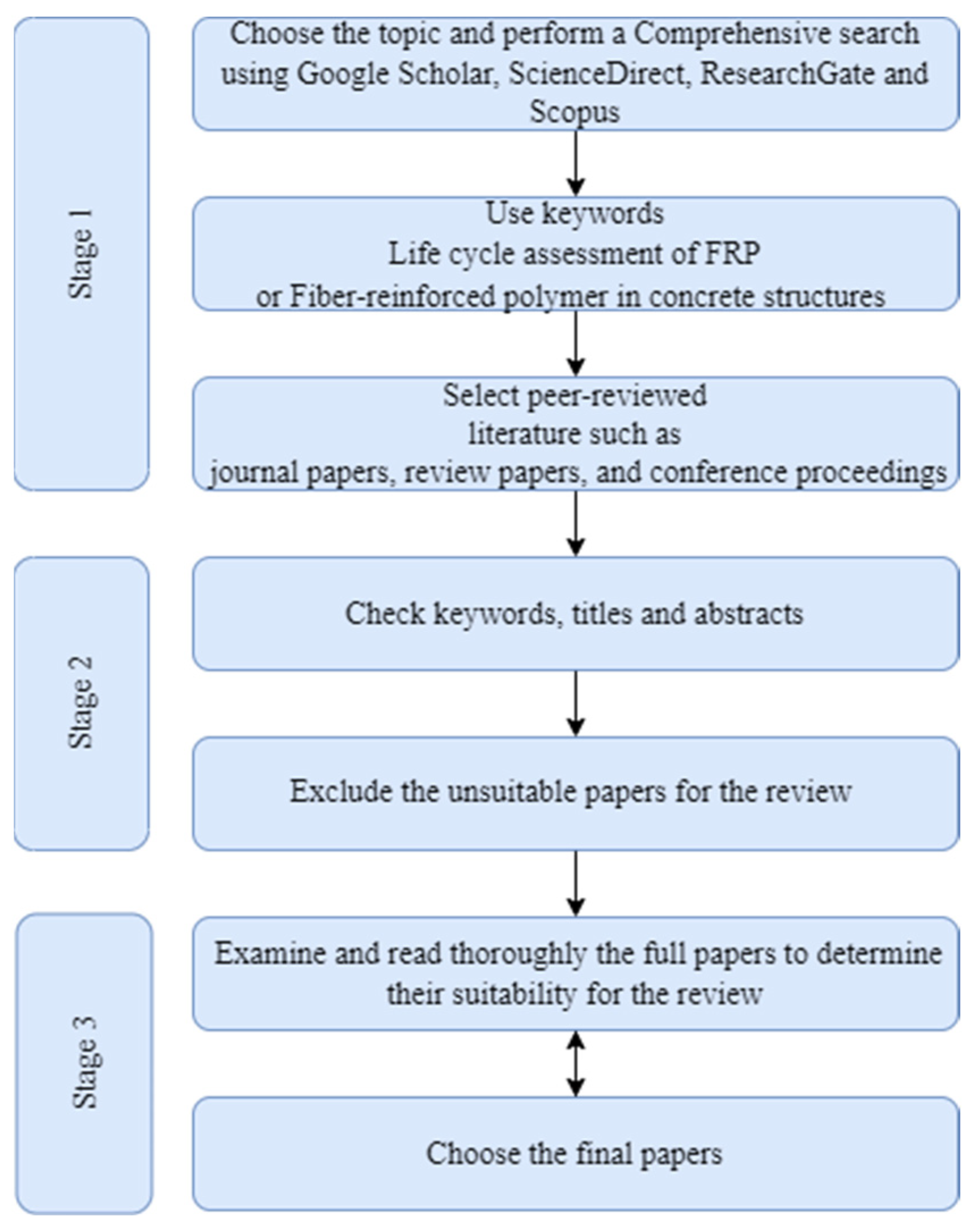
2. Research Methods
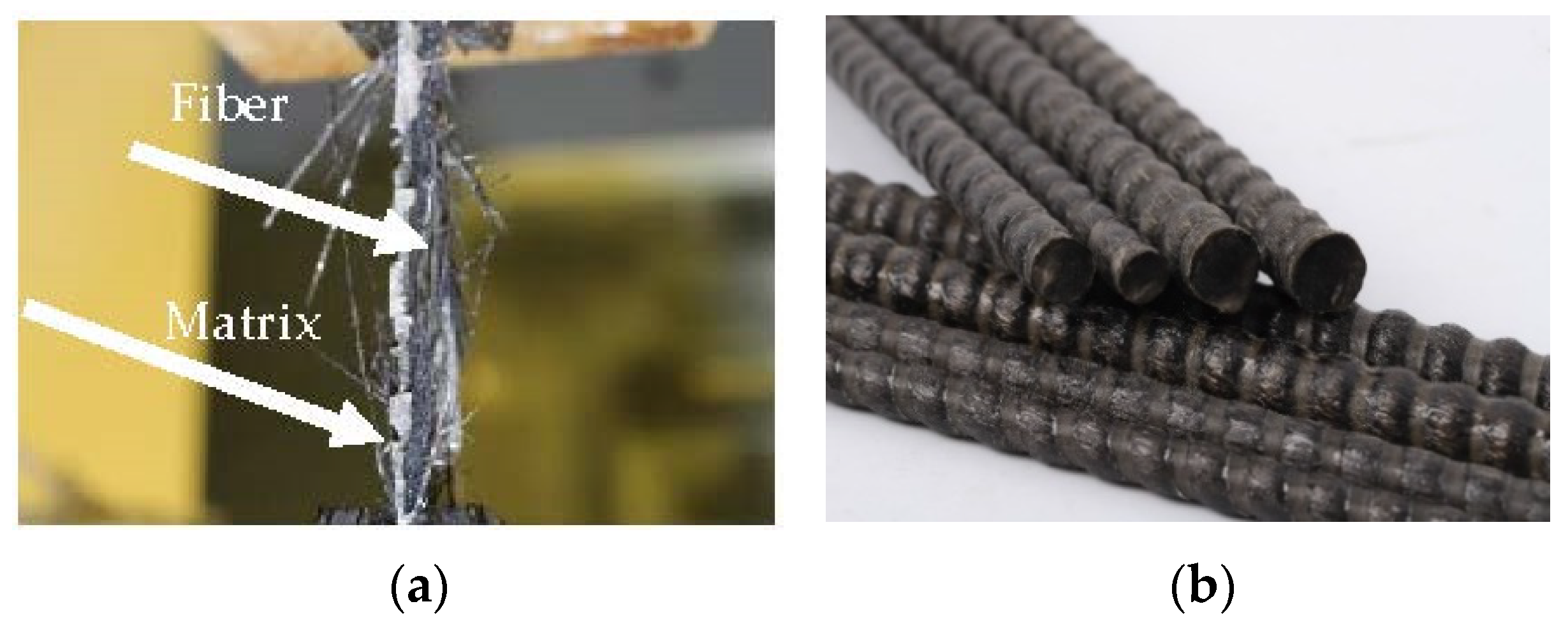
3. Materials and Mechanical Behavior of FRPs
3.1. Mechanical Behavior of FRP Composites
3.1.1. CFRP Composites
3.1.2. GFRP Composites
3.1.3. BFRP Composites
3.1.4. AFRP Composites
3.1.5. Matrix of FRPs
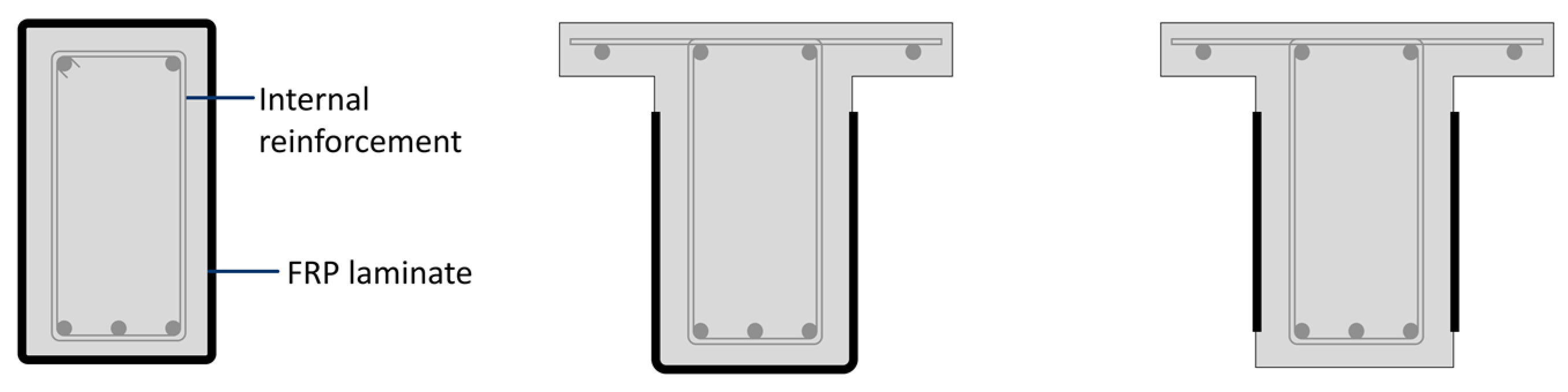
3.2. Strengthening of RC Beams Using FRP Composites
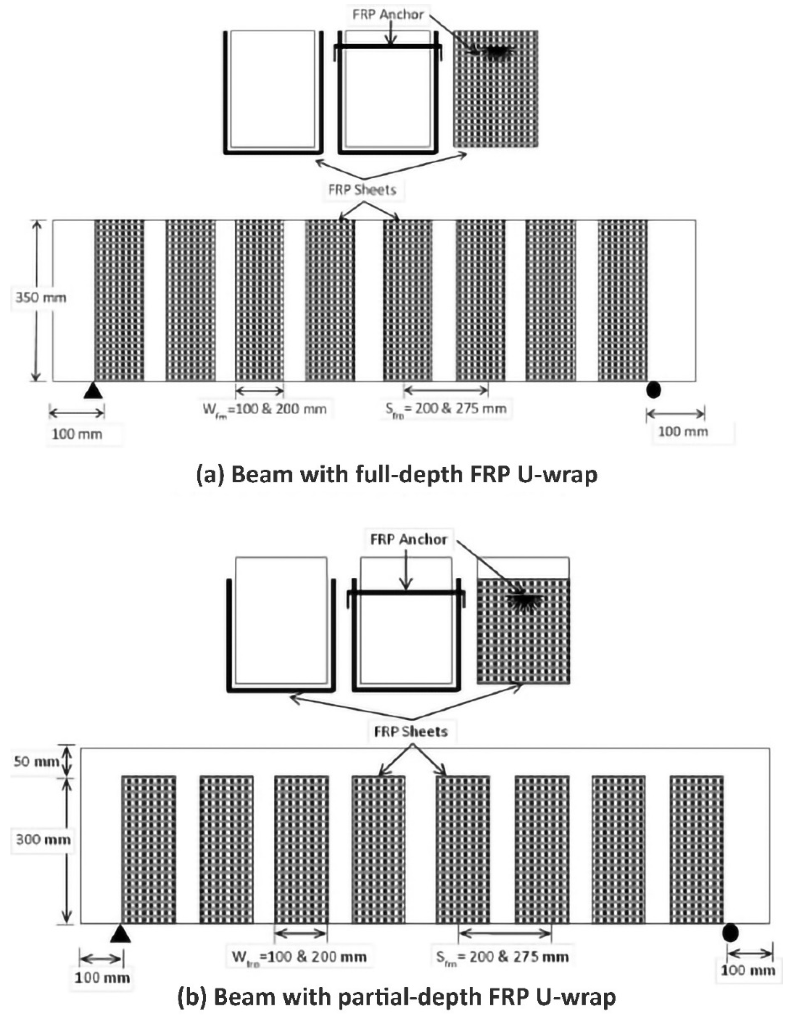
Strengthening Patterns
- Fully wrapped;
- Wrapped on three sides (U-wrap);
- Two-sided FRP strips.
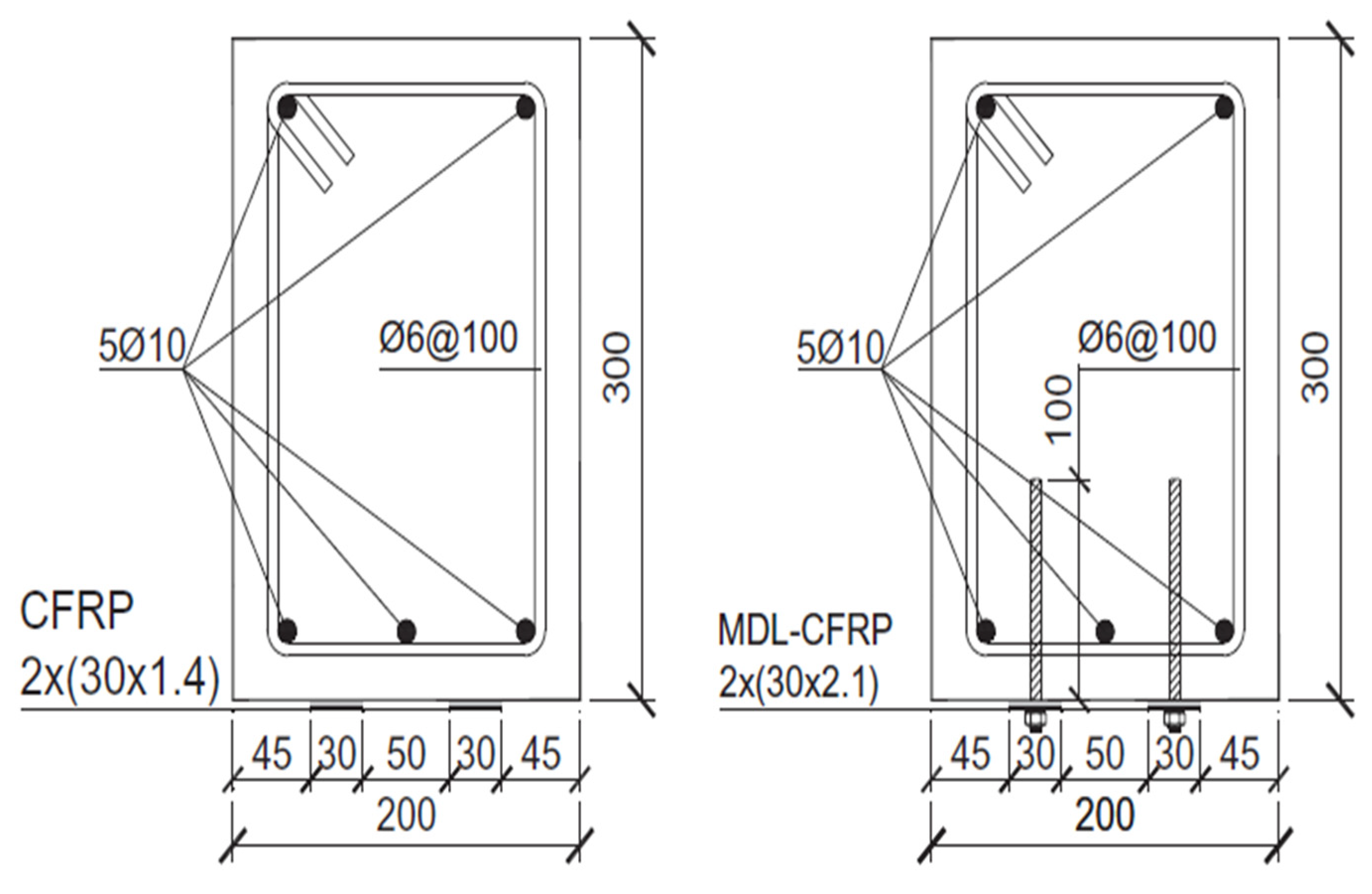
3.3. Anchorage System for Shear
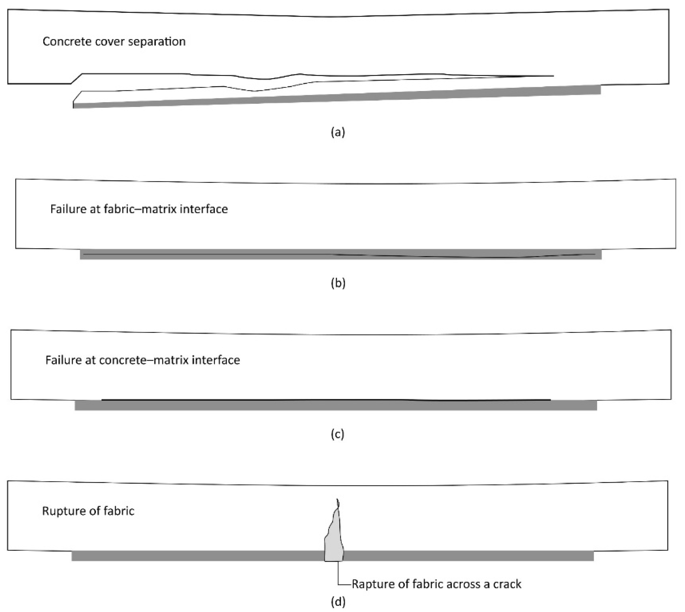
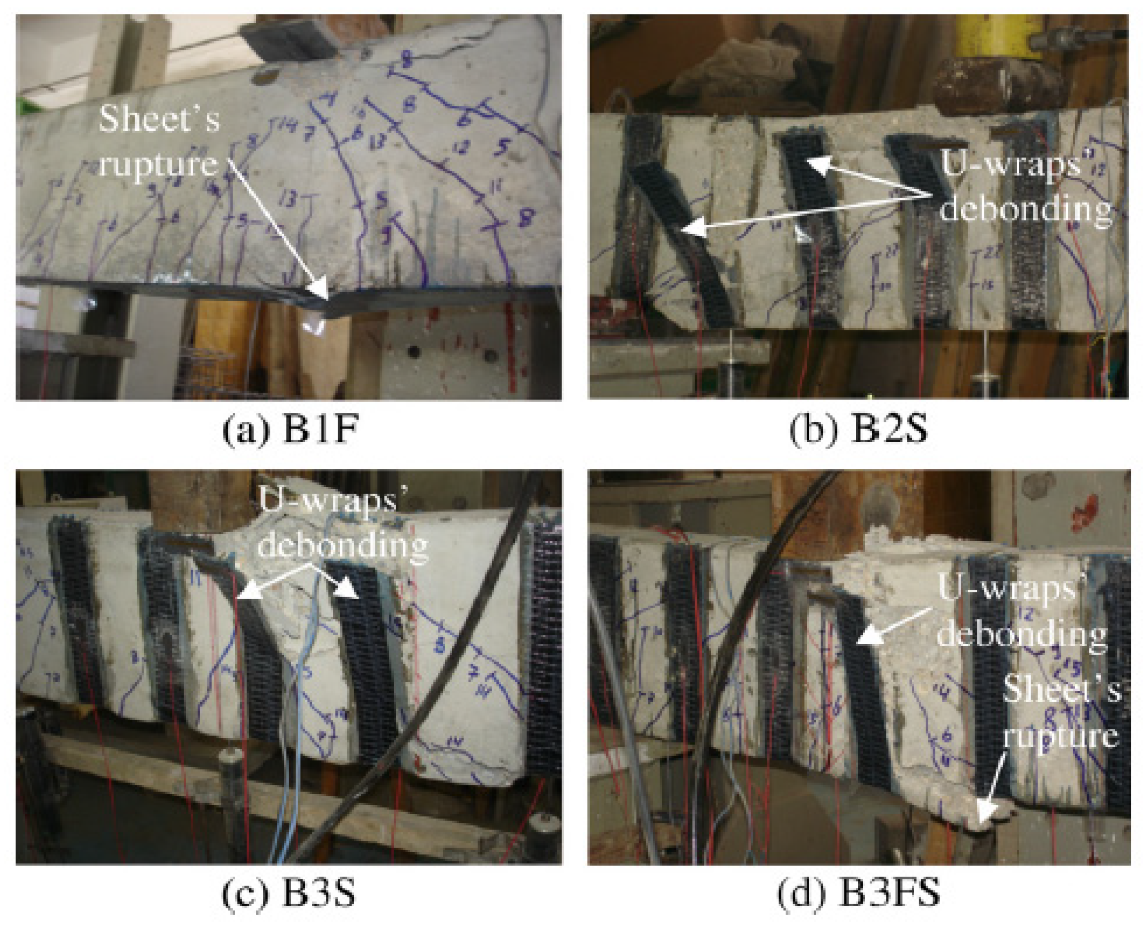
3.4. Failure Modes
3.4.1. Concrete Separation
3.4.2. Debonding of FRP
3.5. Beam Strengthening in Shear
3.6. Beam Strengthening in Flexure
3.7. Strengthening of RC Columns Using FRP
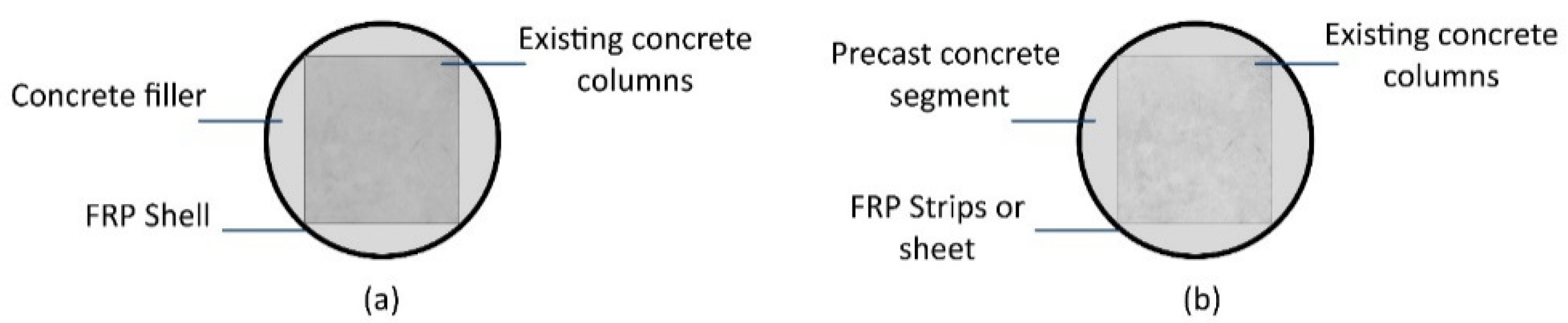
3.7.1. Wrapped Concrete Columns with FRP
3.7.2. Advantages of Wrapped Concrete Columns with FRP
3.7.3. Different Parameters Affecting the Confinement of RC Columns
3.7.4. Slenderness Ratio
3.7.5. The Shape of Concrete Columns
3.7.6. Concrete Strength and Types
3.7.7. Orientation of Fiber Effects
3.7.8. Stress–Strain Behavior of FRP
3.7.9. Axial Loads on FRP Columns
3.7.10. Experimental Findings
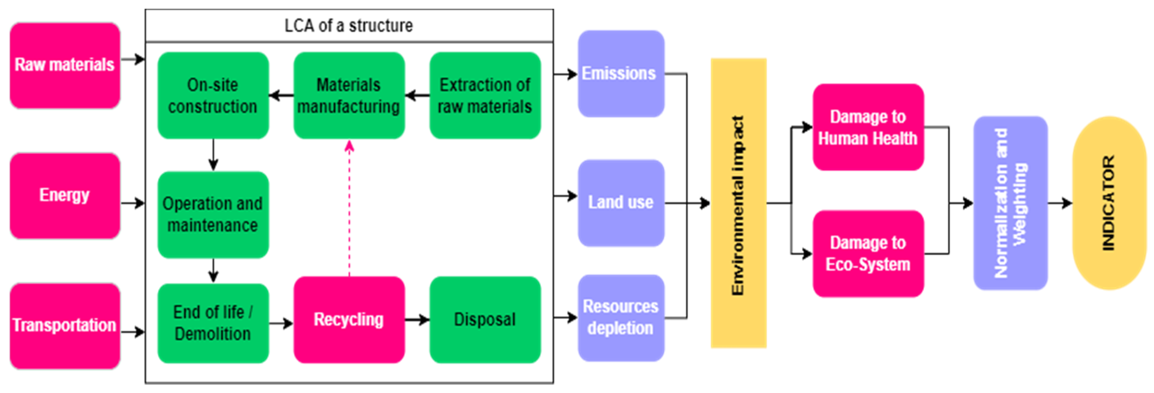
4. Environmental Performance of FRP
4.1. Life Cycle Assessment of FRP Used in Beams
4.2. Life Cycle Assessment of FRP Used in Bridges
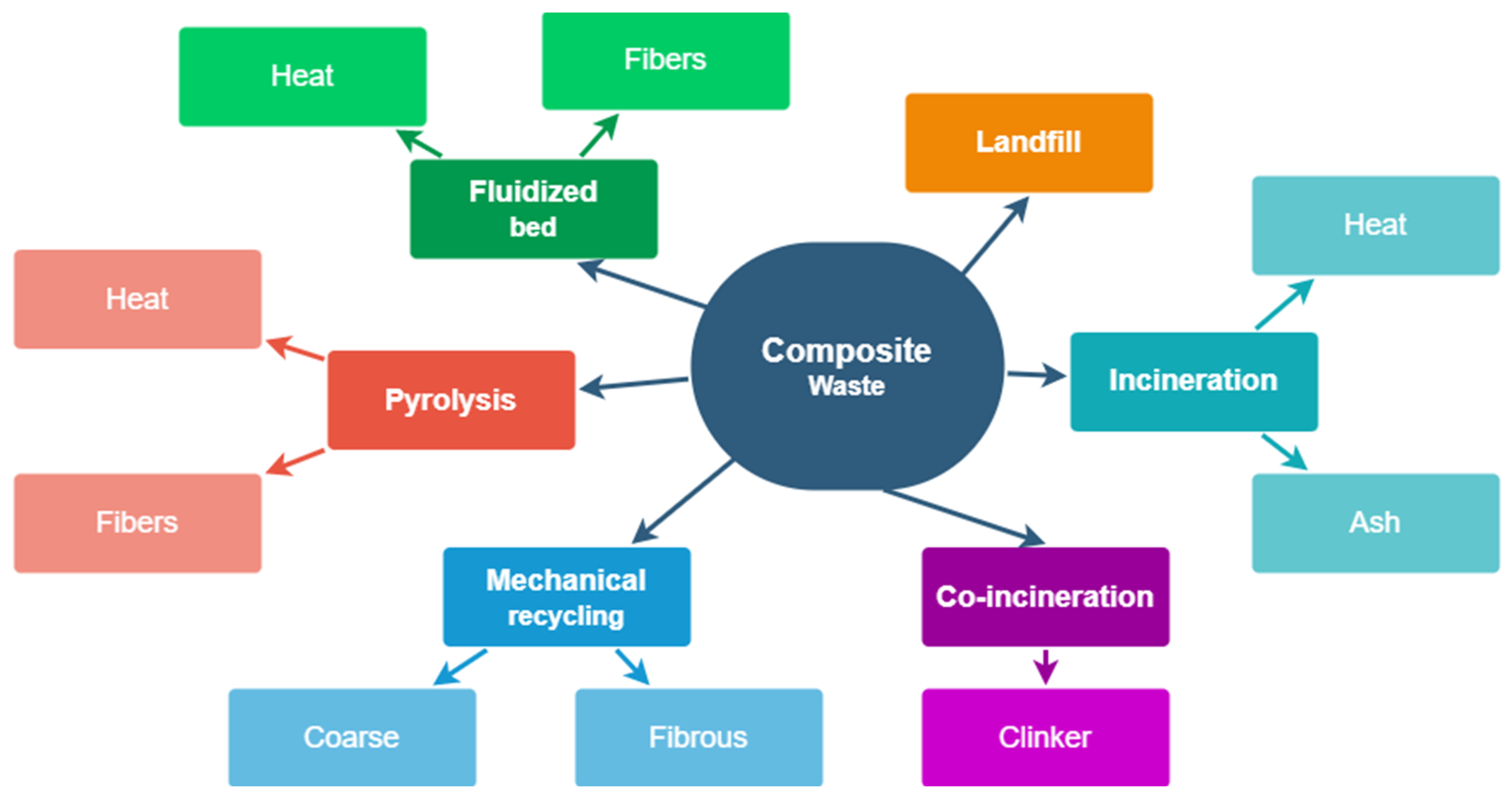
4.3. Life Cycle Assessment of FRP Waste Management
5. Conclusions and Discussion
- Carbon, glass, basalt and aramid are strengthening fibers that are combined with a matrix to produce FRP composite systems. Moreover, some new materials have huge potential to be used as strengthening materials. External FRP strengthening provides a number of benefits over other materials, such as having the ability to resist corrosion, a lower maintenance cost and reduced construction time.
- When FRP is used as a strengthening material to any structural element, such as beams, its influence in terms of the reaction with the ecosystem, long-term service and properties should be considered. However, over the years, a great reputation has been obtained by FRP composites, which has made international construction and design agencies offer construction and design codes.
- FRP composite usage in the industry is significantly advancing over time; thus, many techniques and methods are still under investigation, such as investigations into the effectiveness of FRP strengthening under fatigue loading.
- The authors have deduced some points: The use of anchors enhances shear capacity by 30–50%. Using U-jackets as an anchor system can change the failure mode from FRP debonding to FRP rupturing. MF-EBR increases the flexural capacity of the beams by almost double the value of the EBR-strengthened beam. The ductility of MF-EBR is double the value of the NSM beams.
- It was found that, as FRP thickness increases, two different things result, which are: load-carrying capacity increases when the FRP rupture is the controlling failure mode, and the flexural stiffness within the elastic range increases.
- Replacing conventional steel reinforcement bars with FRP bars as partial reinforcement or total reinforcement improves the stiffness and capacity of the structural members. However, due to its brittle properties, large crack widths are experienced for structural members with high reinforcement ratios of FRP bars. Therefore, a hybrid system may be explored to provide ductility to the structure and inhibit corrosion problems.
- The environmental impact of BFRP rebars is smaller than that of traditional steel, in which a reduction in the emissions emitted to the environment is expected. BFRP rebars are a promising option for RC members in contrast to steel rebars as a result of their light weight and high strength.
- Adopting the utilization of sea-sand and seawater in concrete leads to a reduction in the environmental impact in comparison to the use of traditional concrete with freshwater and river sand. GFRP-SWSSC beams and CFRP-SWSSC beams have a better environmental impact compared to steel-reinforced beams.
- The use of GFRP, CFRP and BFRP in structures instead of steel may lead to reduced energy consumption and CO2 emissions, thus reducing their environmental impacts over their life cycles.
- Many researchers have focused on evaluating the LCA of FRPs in structural members. Nevertheless, some aspects still need to be addressed to explain the environmental impact of FRP and to enhance the quality of results of the life cycle assessment.
- The interaction between economic impacts and environmental impacts of distinct FRPs should be explored, evaluated and compared to conventional materials such as steel to encourage decision makers and buyers to increase their use of FRP to have a better substitute in the future for other reinforcing materials in structural elements.
- FRPs were mainly used in literature as a partial reinforcement in structural members to replace steel; therefore, it was suggested by the authors to apply comprehensive LCA studies for different FRPs, where they are utilized as a full-scale reinforcement instead of traditional steel for structural members.
- Many researchers have evaluated the life cycle assessment of different FRPs by applying cradle-to-gate boundaries; therefore, extra LCA studies considering the full life cycle of the FRP are required, beginning with obtaining raw materials and ending with the final disposal of the FRP (cradle to grave).
- Additional LCA studies have been suggested by the authors to be applied to evaluate the environmental impacts of utilizing FRPs as a non-corrosive reinforcement in concrete structures when seawater is replaced by freshwater in concrete.
- Enhancing and developing the design codes for FRPs used in RC beams and bridges can encourage the progressive use of FRPs in construction.
- FRP materials cause higher carbon emissions compared to conventional materials during the production stage, but high carbon emissions are compensated during maintenance, construction or disposal phases due to the light weight of FRP decks. Therefore, bridges with FRP decks have less energy consumption and carbon emissions compared to bridges with traditional materials.
Author Contributions
Funding
Data Availability Statement
Conflicts of Interest
References
- World Bank Industry (Including Construction), Value Added (% of GDP). Available online: https://data.worldbank.org/indicator/NV.IND.TOTL.ZS (accessed on 18 May 2022).
- Ding, G.K.C. Life Cycle Assessment (LCA) of Sustainable Building Materials: An Overview. In Eco-Efficient Construction and Building Materials: Life Cycle Assessment (LCA), Eco-Labelling and Case Studies; Elsevier Inc.: Amsterdam, The Netherlands, 2013; pp. 38–62. ISBN 9780857097675. [Google Scholar]
- Ramesh, T.; Prakash, R.; Shukla, K.K. Life Cycle Energy Analysis of Buildings: An Overview. Energy Build. 2010, 42, 1592–1600. [Google Scholar] [CrossRef]
- Mokhlesian, S.; Holmén, M. Business Model Changes and Green Construction Processes. Constr. Manag. Econ. 2012, 30, 761–775. [Google Scholar] [CrossRef]
- El-Tahan, M.; Galal, K.; Hoa, V.S. New Thermoplastic CFRP Bendable Rebars for Reinforcing Structural Concrete Elements. Compos. Part B Eng. 2013, 45, 1207–1215. [Google Scholar] [CrossRef]
- Lee, L.S.; Jain, R. The Role of FRP Composites in a Sustainable World. Clean Technol. Environ. Policy 2009, 11, 247–249. [Google Scholar] [CrossRef]
- Sbahieh, S.; Tahir, F.; Al-Ghamdi, S.G. Environmental and Mechanical Performance of Different Fiber Reinforced Polymers in Beams. Mater. Today Proc. 2022, 62, 3548–3552. [Google Scholar] [CrossRef]
- Brigante, D. New Composite Materials; Springer International Publishing Switzerland: Napoli, Italy, 2014; ISBN 978-3-319-01636-8. [Google Scholar]
- Mugahed Amran, Y.H.; Alyousef, R.; Rashid, R.S.M.; Alabduljabbar, H.; Hung, C.-C. Properties and Applications of FRP in Strengthening RC Structures: A Review. Structures 2018, 16, 208–238. [Google Scholar] [CrossRef]
- Teng, J.G.; Chen, J.F.; Smith, S.T.; Lam, L. Behaviour and Strength of FRP-Strengthened RC Structures: A State-of-the-Art Review. Proc. Inst. Civ. Eng.-Struct. Build. 2003, 156, 51–62. [Google Scholar] [CrossRef]
- Rami Hamad, J.A.; Megat Johari, M.A.; Haddad, R.H. Mechanical Properties and Bond Characteristics of Different Fiber Reinforced Polymer Rebars at Elevated Temperatures. Constr. Build. Mater. 2017, 142, 521–535. [Google Scholar] [CrossRef]
- Van Den Einde, L.; Zhao, L.; Seible, F. Use of FRP Composites in Civil Structural Applications. Constr. Build. Mater. 2003, 17, 389–403. [Google Scholar] [CrossRef]
- Zaman, A.; Gutub, S.A.; Wafa, M.A. A Review on FRP Composites Applications and Durability Concerns in the Construction Sector. J. Reinf. Plast. Compos. 2013, 32, 1966–1988. [Google Scholar] [CrossRef]
- Thériault, M.; Benmokrane, B. Effects of FRP Reinforcement Ratio and Concrete Strength on Flexural Behavior of Concrete Beams. J. Compos. Constr. 1998, 2, 7–16. [Google Scholar] [CrossRef]
- Hassan, T.; Rizkalla, S.; Abdelrahman, A.; Tadros, G. Design Recommendations for Bridge Deck Slabs Reinforced by Fiber Reinforced Polymers. Aci Special Publ. 1999, 188, 313–323. [Google Scholar]
- Attia, K.; El Refai, A.; Alnahhal, W. Flexural Behavior of Basalt Fiber–Reinforced Concrete Slab Strips with BFRP Bars: Experimental Testing and Numerical Simulation. J. Compos. Constr. 2020, 24, 04020007. [Google Scholar] [CrossRef]
- Ibrahim, M.; Ebead, U.; Al-Ansari, M. Life Cycle Assessment for Fiber-Reinforced Polymer (FRP) Composites Used in Concrete Beams: A State-of-the-Art Review. In Proceedings of the International Conference on Civil Infrastructure and Construction (CIC 2020), Doha, Qatar, 2–5 February 2020; Qatar University Press: Doha, Qatar, 2020; pp. 777–784. [Google Scholar]
- Titirla, M.; Michel, L.; Ferrier, E. Mechanical Behaviour of Glued-in Rods (Carbon and Glass Fibre-Reinforced Polymers) for Timber Structures—An Analytical and Experimental Study. Compos. Struct. 2019, 208, 70–77. [Google Scholar] [CrossRef]
- Prota, A.; Nanni, A.; Gaetano, M.; Edoardo, C. Selective Upgrade of Beam-Column Joints with Composites. In Proceedings of the International Conference on FRP Composites in Civil Engineering, Hong Kong, China, 12–15 December 2001; pp. 919–926. [Google Scholar]
- Teng, J.G.; Yu, T.; Wong, Y.L.; Dong, S.L. Hybrid FRP–Concrete–Steel Tubular Columns: Concept and Behavior. Constr. Build. Mater. 2007, 21, 846–854. [Google Scholar] [CrossRef]
- Hutchinson, R.; Tadros, G.; Kroman, J.; Rizkalla, S. Use of Externally Bonded FRP Systems for Rehabilitation of Bridges in Western Canada. Am. Concr. Inst. ACI Spec. Publ. 2003, 215, 239–248. [Google Scholar]
- Gudonis, E.; Timinskas, E.; Gribniak, V.; Kaklauskas, G.; Arnautov, A.K.; Tamulėnas, V. FRP Reinforcement for Concrete Structures: State-of-The-Art Review of Application and Design. Eng. Struct. Technol. 2014, 5, 147–158. [Google Scholar] [CrossRef]
- Titirla, M.D.; Ferrier, E.; Michel, L. On the Mechanical Behaviour of Innovative Moment Connections between Composite Floor Panels and Glulam Columns. Int. J. Archit. Herit. 2021, 15, 321–333. [Google Scholar] [CrossRef]
- Kišiček, T.; Stepinac, M.; Renić, T.; Hafner, I.; Lulić, L. Strengthening of Masonry Walls with FRP or TRM. J. Croat. Assoc. Civ. Eng. 2020, 72, 937–953. [Google Scholar] [CrossRef]
- Sbahieh, S.; Teymur, B. The Effect of Fiber Reinforcement on the Behavior of Cemented Sand. In Proceedings of the XVII European Conference on Soil Mechanics and Geotechnical Engineering, Reykjavik, Iceland, 1–7 September 2019; pp. 2823–2830. [Google Scholar] [CrossRef]
- Benmoktane, B.; Masmoudi, R.; Challal, O. Glass Fibre Reinforced Plastic (GFRP) Rebars for Concrete Structures. Constr. Build. Mater. 1995, 9, 353–364. [Google Scholar] [CrossRef]
- Maxineasa, S.G.; Taranu, N. Life Cycle Analysis of Strengthening Concrete Beams with FRP. In Eco-Efficient Repair and Rehabilitation of Concrete Infrastructures; Elsevier: Amsterdam, The Netherlands, 2018; pp. 673–721. [Google Scholar]
- Altin Karataş, M.; Gökkaya, H. A Review on Machinability of Carbon Fiber Reinforced Polymer (CFRP) and Glass Fiber Reinforced Polymer (GFRP) Composite Materials. Def. Technol. 2018, 14, 318–326. [Google Scholar] [CrossRef]
- Sathishkumar, T.; Satheeshkumar, S.; Naveen, J. Glass fiber-reinforced polymer composites—A review. J. Reinf. Plast. Compos. 2014, 33, 1258–1275. [Google Scholar] [CrossRef]
- Saadatmanesh, H.; Ehsani, M.R. RC Beams Strengthened with GFRP Plates. I: Experimental Study. J. Struct. Eng. 1992, 117, 3417–3433. [Google Scholar] [CrossRef]
- Tahir, F.; Sbahieh, S.; Al-Ghamdi, S.G. Environmental Impacts of Using Recycled Plastics in Concrete. Mater. Today Proc. 2022, 62, 4013–4017. [Google Scholar] [CrossRef]
- ISO 14040:2006; Environmental Management—Life Cycle Assessment—Principles and Framework (En). ISO: London, UK, 2006.
- Mannan, M.; Al-Ansari, T.; Mackey, H.R.; Al-Ghamdi, S.G. Quantifying the Energy, Water and Food Nexus: A Review of the Latest Developments Based on Life-Cycle Assessment. J. Clean. Prod. 2018, 193, 300–314. [Google Scholar] [CrossRef]
- Dong, S.; Li, C.; Xian, G. Environmental Impacts of Glass- and Carbon-Fiber-Reinforced Polymer Bar-Reinforced Seawater and Sea Sand Concrete Beams Used in Marine Environments: An LCA Case Study. Polymers 2021, 13, 154. [Google Scholar] [CrossRef]
- Garg, N.; Shrivastava, S. Environmental and Economic Comparison of FRP Reinforcements and Steel Reinforcements in Concrete Beams Based on Design Strength Parameter. In Proceedings of the UKIERI Concrete Congress, Jalandhar, India, 5–8 March 2019; Dr B R Ambedkar National Institute of Technology: Jalandhar, India, 2019. [Google Scholar]
- Pavlović, A.; Donchev, T.; Petkova, D.; Staletović, N. Sustainability of Alternative Reinforcement for Concrete Structures: Life Cycle Assessment of Basalt FRP Bars. Constr. Build. Mater. 2022, 334, 127424. [Google Scholar] [CrossRef]
- Alsabri, A.; Tahir, F.; Al-Ghamdi, S.G. Environmental Impacts of Polypropylene (PP) Production and Prospects of Its Recycling in the GCC Region. Mater. Today Proc. 2022, 56, 2245–2251. [Google Scholar] [CrossRef]
- Alsabri, A.; Tahir, F.; Al-Ghamdi, S.G. Life-Cycle Assessment of Polypropylene Production in the Gulf Cooperation Council (GCC) Region. Polymers 2021, 13, 3793. [Google Scholar] [CrossRef]
- Hoffard, T.A.; Malvar, L.J. Fiber-Reinforced Polymer Composites in Bridges: A State-of-the-Art Report; Naval Facilities Engineering command Port Hueneme ca Engineering Service Center: Port Hueneme, CA, USA, 2005.
- Banibayat, P. Experimental Investigation of the Mechanical and Creep Rupture Properties of Basalt Fiber Reinforced Polymer (BFRP) Bars; The University of Akron: Akron, OH, USA, 2011; ISBN 1-267-12311-7. [Google Scholar]
- Elkington, M.; Bloom, D.; Ward, C.; Chatzimichali, A.; Potter, K. Hand Layup: Understanding the Manual Process. Adv. Manuf. Polym. Compos. Sci. 2015, 1, 138–151. [Google Scholar] [CrossRef]
- Hollaway, L.C. Polymer Composites in Construction: A Brief History. Proc. Inst. Civ. Eng.-Eng. Comput. Mech. 2009, 162, 107–118. [Google Scholar] [CrossRef]
- Zhang, C. Life Cycle Assessment (LCA) of Fibre Reinforced Polymer (FRP) Composites in Civil Applications. In Eco-Efficient Construction and Building Materials; Elsevier: Amsterdam, The Netherlands, 2014; pp. 565–591. [Google Scholar]
- Shakir Abbood, I.; Odaa, S.A.; Hasan, K.F.; Jasim, M.A. Properties Evaluation of Fiber Reinforced Polymers and Their Constituent Materials Used in Structures—A Review. Mater. Today Proc. 2021, 43, 1003–1008. [Google Scholar] [CrossRef]
- Evans, J.W.; De Jonghe, L.C. Advanced Materials and Processes. In The Production and Processing of Inorganic Materials; Evans, J.W., De Jonghe, L.C., Eds.; Springer International Publishing: Cham, Switzerland, 2016; pp. 477–511. ISBN 978-3-319-48163-0. [Google Scholar]
- Ahmed, A.; Guo, S.; Zhang, Z.; Shi, C.; Zhu, D. A Review on Durability of Fiber Reinforced Polymer (FRP) Bars Reinforced Seawater Sea Sand Concrete. Constr. Build. Mater. 2020, 256, 119484. [Google Scholar] [CrossRef]
- Younis, A.; Ebead, U.; Suraneni, P.; Nanni, A. Short-Term Flexural Performance of Seawater-Mixed Recycled-Aggregate GFRP-Reinforced Concrete Beams. Compos. Struct. 2020, 236, 111860. [Google Scholar] [CrossRef]
- Wang, Z.; Zhao, X.-L.; Xian, G.; Wu, G.; Singh Raman, R.K.; Al-Saadi, S.; Haque, A. Long-Term Durability of Basalt- and Glass-Fibre Reinforced Polymer (BFRP/GFRP) Bars in Seawater and Sea Sand Concrete Environment. Constr. Build. Mater. 2017, 139, 467–489. [Google Scholar] [CrossRef]
- Saafi, M.; Toutanji, H. Flexural Capacity of Prestressed Concrete Beams Reinforced with Aramid Fiber Reinforced Polymer (AFRP) Rectangular Tendons. Constr. Build. Mater. 1998, 12, 245–249. [Google Scholar] [CrossRef]
- Bai, J. Advanced Fibre-Reinforced Polymer (FRP) Composites for Structural Applications; Elsevier: Amsterdam, The Netherlands, 2013; ISBN 0-85709-864-0. [Google Scholar]
- Kotynia, R.; Abdel Baky, H.; Neale, K.W.; Ebead, U.A. Flexural Strengthening of RC Beams with Externally Bonded CFRP Systems: Test Results and 3D Nonlinear FE Analysis. J. Compos. Constr. 2008, 12, 190–201. [Google Scholar] [CrossRef]
- Imran, M.; Shafiq, N.; Akbar, I. Strengthening Schemes for Flexure and Torsion Using FRP Laminates: A State of Art Review. Appl. Mech. Mater. 2014, 567, 511–516. [Google Scholar] [CrossRef]
- Garcia, J.; Sun, W.; Kim, C.; Wassim, M.; Jirsa, J.O. Procedures for the Installation and Quality Control of Anchored CFRP Sheets for Shear Strengthening of Concrete Bridge Girders (Report FHWA/TX-13/5-6306-01-1); University of Texas: Austin, TX, USA, 2014; Volume 7. [Google Scholar]
- Oluwafunmilayo, A.; El-Maaddawy, T.; Ahmed, E.R. Numerical Simulation and Experimental Testing of Concrete Beams Strengthened in Shear with Fabric-Reinforced Cementitious Matrix. J. Compos. Constr. 2016, 20, 04016056. [Google Scholar] [CrossRef]
- Tetta, Z.C.; Koutas, L.N.; Bournas, D.A. Textile-Reinforced Mortar (TRM) versus Fiber-Reinforced Polymers (FRP) in Shear Strengthening of Concrete Beams. Compos. Part B Eng. 2015, 77, 338–348. [Google Scholar] [CrossRef]
- Awani, O.; El-Maaddawy, T.; Ismail, N. Fabric-Reinforced Cementitious Matrix: A Promising Strengthening Technique for Concrete Structures. Constr. Build. Mater. 2017, 132, 94–111. [Google Scholar] [CrossRef]
- Hollaway, L.C. A Review of the Present and Future Utilisation of FRP Composites in the Civil Infrastructure with Reference to Their Important In-Service Properties. Constr. Build. Mater. 2010, 24, 2419–2445. [Google Scholar] [CrossRef]
- Baggio, D.; Soudki, K.; Noël, M. Strengthening of Shear Critical RC Beams with Various FRP Systems. Constr. Build. Mater. 2014, 66, 634–644. [Google Scholar] [CrossRef]
- El-Ghandour, A.A. Experimental and Analytical Investigation of CFRP Flexural and Shear Strengthening Efficiencies of RC Beams. Constr. Build. Mater. 2011, 25, 1419–1429. [Google Scholar] [CrossRef]
- Spadea, G.; Bencardino, F.; Sorrenti, F.; Narayan, R. Structural Effectiveness of FRP Materials in Strengthening RC Beams. Eng. Struct. 2015, 99, 631–641. [Google Scholar] [CrossRef]
- Ceroni, F. Experimental Performances of RC Beams Strengthened with FRP Materials. Constr. Build. Mater. 2010, 24, 1547–1559. [Google Scholar] [CrossRef]
- Sena-cruz, J.M.; Barros, J.A.O.; Coelho, M.R.F.; Silva, L.F.F.T. Efficiency of Different Techniques in Flexural Strengthening of RC Beams under Monotonic and Fatigue Loading. Constr. Build. Mater. J. 2012, 29, 175–182. [Google Scholar] [CrossRef]
- Khalifa, A.M. Flexural Performance of RC Beams Strengthened with near Surface Mounted CFRP Strips. Alex. Eng. J. 2016, 55, 1497–1505. [Google Scholar] [CrossRef]
- Chen, W.; Pham, T.M.; Sichembe, H.; Chen, L.; Hao, H. Experimental Study of Fl Exural Behaviour of RC Beams Strengthened by Longitudinal and U-Shaped Basalt FRP Sheet. Compos. Part B 2018, 134, 114–126. [Google Scholar] [CrossRef]
- Nayak, A.N.; Kumari, A.; Swain, R.B. Strengthening of RC Beams Using Externally Bonded Fibre Reinforced Polymer Composites. Structures 2018, 14, 137–152. [Google Scholar] [CrossRef]
- Dong, J.; Wang, Q.; Guan, Z. Composites: Part B Structural Behaviour of RC Beams with External Flexural and Flexural—Shear Strengthening by FRP Sheets. Compos. Part B 2013, 44, 604–612. [Google Scholar] [CrossRef]
- Sen, T.; Reddy, H.N.J. Strengthening of RC Beams in Flexure Using Natural Jute Fibre Textile Reinforced Composite System and Its Comparative Study with CFRP and GFRP Strengthening Systems. Int. J. Sustain. Built Environ. 2014, 2, 41–55. [Google Scholar] [CrossRef]
- Fu, B.; Chen, G.M.; Teng, J.G. Mitigation of Intermediate Crack Debonding in FRP-Plated RC Beams Using FRP U-Jackets. Compos. Struct. 2017, 176, 883–897. [Google Scholar] [CrossRef]
- Chen, C.; Wang, X.; Sui, L.; Xing, F.; Chen, X.; Zhou, Y. In Fl Uence of FRP Thickness and Con Fi Ning e Ff Ect on Fl Exural Performance of HB-Strengthened RC Beams. Compos. Part B 2019, 161, 55–67. [Google Scholar] [CrossRef]
- Böer, P.; Holliday, L.; Kang, T.H. Independent Environmental Effects on Durability of Fiber-Reinforced Polymer Wraps in Civil Applications: A Review. Constr. Build. Mater. 2013, 48, 360–370. [Google Scholar] [CrossRef]
- Mortazavi, A.A.; Pilakoutas, K.; Son, K.S. RC Column Strengthening by Lateral Pre-Tensioning of FRP. Constr. Build. Mater. 2003, 17, 491–497. [Google Scholar] [CrossRef]
- Hong, W.-K.; Kim, H.-C. Behavior of Concrete Columns Confined by Carbon Composite Tubes. Can. J. Civ. Eng. 2004, 31, 178–188. [Google Scholar] [CrossRef]
- Kim, H.; Lee, K.H.; Lee, Y.H.; Lee, J. Axial Behavior of Concrete-Filled Carbon Fiber-Reinforced Polymer Composite Columns. Struct. Des. Tall Spec. Build. 2012, 21, 178–193. [Google Scholar] [CrossRef]
- Vincent, T.; Ozbakkaloglu, T. Influence of Fiber Orientation and Specimen End Condition on Axial Compressive Behavior of FRP-Confined Concrete. Constr. Build. Mater. 2013, 47, 814–826. [Google Scholar] [CrossRef]
- Teng, J.; Lam, L. Behavior and Modeling of Fiber Reinforced Polymer-Confined Concrete. J. Struct. Eng. 2004, 130, 1713–1723. [Google Scholar] [CrossRef]
- Qasrawi, Y.; Heffernan, P.J.; Fam, A. Performance of Concrete-Filled FRP Tubes under Field Close-in Blast Loading. J. Compos. Constr. 2015, 19, 04014067. [Google Scholar] [CrossRef]
- Beddiar, A.; Zitoune, R.; Collombet, F.; Grunevald, Y.H.; Abadlia, M.T.; Bourahla, N. Compressive Behaviour of Concrete Elements Confined with GFRP-Prefabricated Bonded Shells. Eur. J. Environ. Civ. Eng. 2015, 19, 65–80. [Google Scholar] [CrossRef]
- Vincent, T.; Ozbakkaloglu, T. Influence of Slenderness on Stress-Strain Behavior of Concrete-Filled FRP Tubes: Experimental Study. J. Compos. Constr. 2015, 19, 04014029. [Google Scholar] [CrossRef]
- Mirmiran, A.; Shahawy, M.; Beitleman, T. Slenderness limit for hybrid FRP-concrete columns. J. Compos. Constr. 2001, 5, 26–34. [Google Scholar] [CrossRef]
- Fitzwilliam, J.; Bisby, L.A. Slenderness Effects on Circular CFRP Confined Reinforced Concrete Columns. J. Compos. Constr. 2010, 14, 280–288. [Google Scholar] [CrossRef]
- Jiang, T.; Teng, J. Behavior and Design of Slender FRP-Confined Circular RC Columns. J. Compos. Constr. 2012, 17, 443–453. [Google Scholar] [CrossRef]
- Siddiqui, N.A.; Alsayed, S.H.; Al-Salloum, Y.A.; Iqbal, R.A.; Abbas, H. Experimental Investigation of Slender Circular RC Columns Strengthened with FRP Composites. Constr. Build. Mater. 2014, 69, 323–334. [Google Scholar] [CrossRef]
- Fam, A.; Schnerch, D.; Rizkalla, S. Rectangular Filament-Wound Glass Fiber Reinforced Polymer Tubes Filled with Concrete under Flexural and Axial Loading: Experimental Investigation. J. Compos. Constr. 2005, 9, 25–33. [Google Scholar] [CrossRef]
- Pessiki, S.; Harries, K.A.; Kestner, J.T.; Sause, R.; Ricles, J.M. Axial Behavior of Reinforced Concrete Columns Confined with FRP Jackets. J. Compos. Constr. 2001, 5, 237–245. [Google Scholar] [CrossRef]
- Mirmiran, A.; Shahawy, M.; Samaan, M.; Echary, H.E.; Mastrapa, J.C.; Pico, O. Effect of column parameters on FRP-confined concrete. J. Compos. Constr. 1998, 2, 175–185. [Google Scholar] [CrossRef]
- Ozbakkaloglu, T.; Xie, T. Geopolymer concrete-filled FRP tubes: Behavior of circular and square columns under axial compression. Compos. B Eng. 2016, 96, 215–230. [Google Scholar] [CrossRef]
- Yan, Z.; Pantelides, C.P.; Reaveley, L.D. Posttensioned FRP composite shells for concrete confinement. J. Compos. Constr. 2007, 11, 81–90. [Google Scholar] [CrossRef]
- Hadi, M.N.S.; Pham, T.M.; Lei, X. New Method of Strengthening Reinforced Concrete Square Columns by Circularizing and Wrapping with Fiber-Reinforced Polymer or Steel Straps. J. Compos. Constr. 2013, 17, 229–238. [Google Scholar] [CrossRef]
- Bhowmik, T.; Tan, K.H.; Balendra, T. Lateral Load-Displacement Response of Low Strength CFRP-Confined Capsule-Shaped Columns. Eng. Struct. 2017, 150, 64–75. [Google Scholar] [CrossRef]
- Vincent, T.; Ozbakkaloglu, T. Influence of Concrete Strength and Confinement Method on Axial Compressive Behavior of FRP Confined High- and Ultra High-Strength Concrete. Compos. B Eng. 2013, 50, 413–428. [Google Scholar] [CrossRef]
- Lim, J.C.; Ozbakkloglu, T. Factors Influencing Hoop Rupture Strains of FRP-Confined Concrete. Appl. Mech. Mater. Trans. Tech. Publ. 2014, 501, 949–953. [Google Scholar] [CrossRef]
- De Diego, A.; Arteaga, Á.; Fernández, J. Strengthening of Square Concrete Columns with Composite Materials. Investigation on the FRP Jacket Ultimate Strain. Compos. Part B Eng. 2019, 162, 454–460. [Google Scholar] [CrossRef]
- ASTM D3039/D3039M-08; Standard Test Method for Tensile Properties of Polymer Matrix Composite Materials. ASTM: West Conshohocken, PA, USA, 2008.
- ISO 527-4:1997; Plastics. Determination of Tensile Properties. Part 4: Test Conditions for Isotropic and Orthotropic Fibre-Reinforced Plastic Composites. ISO: London, UK, 1997.
- ASTM D2290-08; Standard Test Method for Apparent Tensile Strength of Plastics or Reinforced Plastic Pipe by Split Disk Method. ASTM: West Conshohocken, PA, USA, 2008.
- Chen, J.F.; Li, S.Q.; Bisby, L.A.; Ai, J. FRP Rupture Strains in the Split-Disk Test. Compos. Part B Eng. 2011, 42, 962–972. [Google Scholar] [CrossRef]
- Mirmiran, A.; Beitelman, T.; Shahawy, M. Tests and modeling of carbon wrapped concrete columns. J. Compos. Part B 2000, 31, 471–480. [Google Scholar]
- Toutanji, H. Stress-Strain Characteristics of Concrete Columns Externally Confined with Advanced Fiber Composite Sheets. ACI Mater. J. 1999, 96, 397–404. [Google Scholar]
- Fib Fédération Internationale du Béton. Fib Bulletin 14, Externally Bonded FRP Reinforcement for RC Structures; Fédération Internationale du Béton: Lausanne, Switzerland, 2001. [Google Scholar]
- Xiao, Y.; Wu, H. Compressive Behavior of Concrete Confined by Carbon Fiber Composite Jackets. J. Mater. Civ. Eng. 2000, 12, 139–146. [Google Scholar] [CrossRef]
- De Lorenzis, L.; Tepfers, R. Comparative Study of Models on Confinement of Concrete Cylinders with Fiber-Reinforced Polymer Composites. J. Compos. Constr. 2003, 7, 219–237. [Google Scholar] [CrossRef]
- Sadeghian, P.; Fam, A. A Rational Approach toward Strain Efficiency Factor of Fiber-Reinforced Polymer-Wrapped Concrete Columns. ACI Struct. J. 2014, 111, 135–144. [Google Scholar]
- Lam, L.; Teng, J.G. Design-Oriented Stress–Strain Model for FRP-Confined Concrete. Constr. Build. Mater. 2003, 17, 471–489. [Google Scholar] [CrossRef]
- Harries, K.A.; Carey, S.A. Shape and “Gap” Effects on the Behavior of Variably Confined Concrete. Cem. Concr. Res. 2003, 33, 881–890. [Google Scholar] [CrossRef]
- Irshidat, M.; Al-Saleh, M.; Al-Shoubaki, M. Using Carbon Nanotubes to Improve Strengthening Efficiency of Carbon Fiber/Epoxy Composites Confined RC Columns. Compos. Struct. 2015, 134, 523–532. [Google Scholar] [CrossRef]
- Irshidat, M.; Al-Saleh, M. Repair of Heat-Damaged RC Columns Using Carbon Nanotubes Modified CFRP. Mater. Struct. 2017, 50, 679. [Google Scholar] [CrossRef]
- Barbero, E.; Tomblin, J. A Phenomenological Design Equation for FRP Columns with Interaction between Local and Global Buckling. Thin-Walled Struct. 1994, 18, 117–131. [Google Scholar] [CrossRef]
- GangaRao, H.; Blandford, M. Critical Buckling Strength Prediction of Pultruded Glass Fiber Reinforced Polymeric Composite Columns. J. Compos. Mater. 2014, 48, 3685–3702. [Google Scholar] [CrossRef]
- Sayyar Roudsari, S.; Hamoush, S.; Mohamad Soleimani, S.; Madandoust, R. Evaluation of Large-Size Reinforced Concrete Columns Strengthened for Axial Load Using Fiber Reinforced Polymers. Eng. Struct. 2019, 178, 680–693. [Google Scholar] [CrossRef]
- Işildar, G.Y.; Morsali, S.; Zar Gari, Z.H. A Comparison LCA of the Common Steel Rebars and FRP. J. Build. Pathol. Rehabil. 2020, 5, 8. [Google Scholar] [CrossRef]
- Maxineasa, S.G.; Services, B.; Taranu, N.; Hudisteanu, I. Environmental impact of fibre reinforced polymers’ constituent materials. In Proceedings of the 15th International Scientific Conference VSU’2015, Sofia, Bulgaria, 4–5 June 2015; pp. 367–372. [Google Scholar]
- Basbagill, J.P.; Lepech, M.D.; Ali, S.M. Human Health Impact as a Boundary Selection Criterion in the Life Cycle Assessment of Pultruded Fiber Reinforced Polymer Composite Materials. J. Ind. Ecol. 2012, 16, 266–275. [Google Scholar] [CrossRef]
- Luijten, C.J.L.M.; Said, M.; Bouwheer, C.H.J.; de Gijt, J.G. From LCA to LCC in Infrastructure: Reducing CO2 Emissions in Infrastructure. In Life-Cycle of Engineering Systems; CRC Press: Boca Raton, FL, USA, 2016; pp. 953–958. [Google Scholar]
- Ebead, U.; Marzouk, H. Fiber-Reinforced Polymer Strengthening of Two-Way Slabs. Struct. J. 2004, 101, 650–659. [Google Scholar]
- Ferrari, G.; Miyamoto, M.; Ferrari, A. New Sustainable Technology for Recycling Returned Concrete. Constr. Build. Mater. 2014, 67, 353–359. [Google Scholar] [CrossRef]
- Inman, M.; Thorhallsson, E.R.; Azrague, K. A Mechanical and Environmental Assessment and Comparison of Basalt Fibre Reinforced Polymer (BFRP) Rebar and Steel Rebar in Concrete Beams. Energy Procedia 2017, 111, 31–40. [Google Scholar] [CrossRef]
- Fořt, J.; Kočí, J.; Černý, R. Environmental Efficiency Aspects of Basalt Fibers Reinforcement in Concrete Mixtures. Energies 2021, 14, 7736. [Google Scholar] [CrossRef]
- Palacios-Munoz, B.; Gracia-Villa, L.; Zabalza-Bribián, I.; López-Mesa, B. Simplified Structural Design and LCA of Reinforced Concrete Beams Strengthening Techniques. Eng. Struct. 2018, 174, 418–432. [Google Scholar] [CrossRef]
- Maxineasa, S.G.; Taranu, N.; Bejan, L.; Isopescu, D.; Banu, O.M. Environmental Impact of Carbon Fibre-Reinforced Polymer Flexural Strengthening Solutions of Reinforced Concrete Beams. Int. J. Life Cycle Assess. 2015, 20, 1343–1358. [Google Scholar] [CrossRef]
- Zhang, Y.; Huang, T.; Wang, Y.; Zhang, J.; Wang, J. Environmental Assessment of Concrete Beams Strengthened with Fibre-Reinforced Polymer. Proc. Inst. Civ. Eng. Eng. Sustain. 2020, 174, 37–45. [Google Scholar] [CrossRef]
- Maxineasa, S.G.; Isopescu, D.N.; Entuc, I.S.; Taranu, N.; Lupu, L.M.; Hudisteanu, I. Environmental Performances of Different Carbon and Glass Fibre Reinforced Polymer Shear Strengthening Solutions of Linear Reinforced Concrete. Bull. Transilv. Univ. Bras. 2018, 11, 107–115. [Google Scholar]
- Taranu, N.; Maxineasa, S.G.; Entue, I.S.; Oprisan, G.; Secu, A. Assessing the environmental impact of a glass fibre reinforced polymer strengthening solution for timber beams. In Proceedings of the 15th International Multidisciplinary Scientific Geoconference Sgem 2015, Albena, Bulgaria, 18–24 June 2015; pp. 65–72. [Google Scholar]
- Mara, V.; Haghani, R.; Harryson, P. Bridge Decks of Fibre Reinforced Polymer (FRP): A Sustainable Solution. Constr. Build. Mater. 2014, 50, 190–199. [Google Scholar] [CrossRef]
- Stoiber, N.; Hammerl, M.; Kromoser, B. Cradle-to-Gate Life Cycle Assessment of CFRP Reinforcement for Concrete Structures: Calculation Basis and Exemplary Application. J. Clean. Prod. 2021, 280, 124300. [Google Scholar] [CrossRef]
- Shimomura, T.; Nishizaki, I.; Tanaka, H. Report on JSCE Committee Activities on LCA and LCC of FRP Infrastructure. Structure 2009, 1, 2. [Google Scholar]
- Cadenazzi, T.; Dotelli, G.; Rossini, M.; Nolan, S.; Nanni, A. Life-Cycle Cost and Life-Cycle Assessment Analysis at the Design Stage of a Fiber-Reinforced Polymer-Reinforced Concrete Bridge in Florida. Adv. Civ. Eng. Mater. 2019, 8, 20180113. [Google Scholar] [CrossRef]
- Mara, V.; Haghani, R.; Sagemo, A.; Storck, L.; Nilsson, D. Comparative Study of Different Bridge Concepts Based on Life-Cycle Cost Analyses and Life-Cycle Assessment. In Proceedings of the 4th Asia-Pacific Conference on FRP in Structures, APFIS 2013, Melbourne, Australia, 11–13 December 2013; pp. 1–6. [Google Scholar]
- Pang, B.; Yang, P.; Wang, Y.; Kendall, A.; Xie, H.; Zhang, Y. Life Cycle Environmental Impact Assessment of a Bridge with Different Strengthening Schemes. Int. J. Life Cycle Assess. 2015, 20, 1300–1311. [Google Scholar] [CrossRef]
- Jena, T.; Kaewunruen, S. Life Cycle Sustainability Assessments of an Innovative FRP Composite Footbridge. Sustainability 2021, 13, 13000. [Google Scholar] [CrossRef]
- Zhang, C.; Lin, W.X.; Abududdin, M.; Canning, L. Environmental Evaluation of FRP in UK Highway Bridge Deck Replacement Applications Based on a Comparative LCA Study. Adv. Mater. Res. 2011, 374–377, 43–48. [Google Scholar] [CrossRef]
- Daniel, R.A. A Composite Bridge Is Favoured by Quantifying Ecological Impact. Struct. Eng. Int. 2010, 20, 385–391. [Google Scholar] [CrossRef]
- Vo Dong, P.A.; Azzaro-Pantel, C.; Cadene, A.-L. Economic and Environmental Assessment of Recovery and Disposal Pathways for CFRP Waste Management. Resour. Conserv. Recycl. 2018, 133, 63–75. [Google Scholar] [CrossRef]
- Vo Dong, P.A.; Azzaro-Pantel, C.; Boix, M.; Jacquemin, L.; Domenech, S. Modelling of Environmental Impacts and Economic Benefits of Fibre Reinforced Polymers Composite Recycling Pathways. Comput. Aided Chem. Eng. 2015, 37, 2009–2014. [Google Scholar] [CrossRef]
- Ribeiro, M.; Fiúza, A.; Ferreira, A.; Dinis, M.; Meira Castro, A.; Meixedo, J.; Alvim, M. Recycling Approach towards Sustainability Advance of Composite Materials’ Industry. Recycling 2016, 1, 178–193. [Google Scholar] [CrossRef]
- Karuppannan Gopalraj, S.; Deviatkin, I.; Horttanainen, M.; Kärki, T. Life Cycle Assessment of a Thermal Recycling Process as an Alternative to Existing CFRP and GFRP Composite Wastes Management Options. Polymers 2021, 13, 4430. [Google Scholar] [CrossRef]
- Li, X.; Bai, R.; McKechnie, J. Environmental and Financial Performance of Mechanical Recycling of Carbon Fibre Reinforced Polymers and Comparison with Conventional Disposal Routes. J. Clean. Prod. 2016, 127, 451–460. [Google Scholar] [CrossRef]
- Witik, R.A.; Teuscher, R.; Michaud, V.; Ludwig, C.; Månson, J.-A.E. Carbon Fibre Reinforced Composite Waste: An Environmental Assessment of Recycling, Energy Recovery and Landfilling. Compos. Part A Appl. Sci. Manuf. 2013, 49, 89–99. [Google Scholar] [CrossRef]


| Type of FRP (Trade Name) | Density kg/m3 | Tensile Strength MPa | Modulus of Elasticity GPa | Elongation% | Coefficient of Thermal Expansion (10–6/°C) | Poisson’s Ratio |
|---|---|---|---|---|---|---|
| Carbon Fibers | ||||||
| Carbon | 1700 | 3700 | 250 | 1.2 | −0.6 up to −0.2 | 0.20 |
| Carbon (high modulus) | 1950 | 2500–4000 | 350–800 | 0.5 | −1.2 up to −0.1 | 0.20 |
| Carbon (high strength) | 1750 | 4800 | 240 | 1.1 | −0.6 up to −0.2 | 0.20 |
| Aramid Fibers | ||||||
| Aramid (Kevlar 29) | 1440 | 2760 | 62 | 4.4 | −2.0 longitudinal 59 radial | 0.35 |
| Aramid (Kevlar 49) | 1440 | 3620 | 124 | 2.2 | −2.0 longitudinal 59 radial | 0.35 |
| Aramid (Kevlar 149) | 1440 | 3450 | 175 | 1.4 | −2.0 longitudinal 59 radial | 0.35 |
| Aramid (Technora H) | 1390 | 3000 | 70 | 4.4 | −2.0 longitudinal 59 radial | 0.35 |
| Aramid (SVM) | 1430 | 3800–4200 | 130 | 3.5 | n/a | n/a |
| Basalt Fibers | ||||||
| Basalt (Albarrie) | 2800 | 4840 | 89 | 3.1 | 8.0 | n/a |
| Basalt (Rockbar) | 1750 | 1000 | 50 | 2.24 | 2.0 | n/a |
| Basalt (BCR) | 1800 | 1100 | 70 | 2.20 | 0.35–0.592 | n/a |
| Basalt (Composite rebar) | 1900 | >900 | 40 | 1.8 | 9–12 | n/a |
| Glass Fibers | ||||||
| Glass (V-rod) | 1250–2500 | 710 | 46.4 | 1.2–5.0 | 6–10 | n/a |
| Glass (Aslan) | 690 | 40.8 | ||||
| Glass (Nefmac) | 600 | 30 | ||||
| Properties | Thermosetting Resins | ||
|---|---|---|---|
| Polyesters | Epoxy | Vinyl-Ester | |
| Density, kg/m3 | 1200–1400 | 1200–1400 | 1150–1350 |
| Tensile strength, MPa | 34.5–104 | 55–130 | 73–81 |
| Deformation modulus, GPa | 2.1–3.45 | 2.75–4.10 | 3.0–3.5 |
| Poisson’s ratio | 0.35–0.39 | 0.38–0.40 | 0.36–0.39 |
| Coefficient of thermal expansion, 10–6/°C | 55–100 | 45–65 | 50–75 |
| Saturation, % | 0.15–0.6 | 0.08–0.15 | 0.14–1.30 |
| Ref. | Beam Description | FRP Type | Strengthened Focus | Strengthening Scheme | Ultimate Load (kN) | Deflection (mm) | Failure Mode | Anchors |
|---|---|---|---|---|---|---|---|---|
| [60] | A1.1 A3.1 | CFRP | Flexure | CFRP laminates to the tension side | 86.8 74.8 | 78.9 61.6 | Debonding of CFRP sheets (total and sudden loss of load capacity) | - |
| [70] | B150A B150B B150C B150D | BFRP | Flexure Flexure Flexure Flexure | BFRP laminates to the tension side U-wrap as anchorage Inclined U-wrap at 45° U-wrap at the midspan only | 74.37 84.90 95.68 82.26 | 18.5 37.56 22.9 19.41 | FRP debonding FRP rupture Compressive failure Cover separation | - - - - |
| [66] | CR3 CR5 | CFRP | Flexural | CFRP laminates | 93.66 121.7 | 13.61 16.31 | Flexural debonding and snapping of CFRP sheet | U-strips at the ends only |
| [66] | SR2 | GFRP | Shear | U-wrap as anchorage | 146.20 | 16.55 | Flexural failure | - |
| [59] | B1F B3FS | CFRP | Flexure Shear | FRP laminates FRP laminates and U-wrap | 170 155 | - - | Flexural failure Combined flexure–shear | - |
| [61] | A5 A9 | CFRP CFRP | Flexure Flexure | FRP laminates NSM | 44.7 45.9 | - - | FRP tensile fracture Cover detachment | - |
| [63] | B-S-4 B-N-2-2 | CFRP CFRP | Flexure Flexure | CFRP laminates NSM | 94.57 91.57 | 13.21 24.5 | Debonding Debonding | - - |
| [62] | EBR MF-EBR NSM | CFRP CFRP CFRP | Flexure Flexure Flexure | CFRP laminates - NSM | 108.4 148.2 147.3 | - - - | Debonding Bearing Rip-off | - Yes - |
| [69] | EB-1-0 HB-1-3 | FRP | Flexure Flexure | FRP laminates Hybrid bond (HB) FRP method | 51.58 54.88 | 19.85 26.99 | Debonding FRP rapture | - - |
| [65] | BT11 BT12 BT21 BT23 | GFRP GFRP GFRP GFRP | Flexure–shear Flexure–shear Flexure–shear Flexure–shear | Bottom and 25 cm of both sides Bottom and 25 cm of both sides Bottom and half of both sides Bottom and half of both sides | 5.6% Mu resistance increase 43.2% Mu resistance increase 61.0% Mu resistance increase 140.0% Mu resistance increase | - - - - | Ductile failure Ductile failure Ductile failure Brittle failure | - - - - |
| [67] | Beam 1 Beam 2 Beam 3 | JFRP CFRP GFRP | Flexure–shear Flexure–shear Flexure–shear | U-wrap for full length U-wrap for full length U-wrap for full length | 130 200 180 | 23.211 16.31 17.62 | Ductile failure (huge deflection) Brittle failure Brittle failure | - - - |
| [58] | Beam1- Control Beam 2 Beam 3 Beam 6 Beam 7 Beam 9 | - CFRP CFRP GFRP GFRP GFRP | - Shear Shear Shear Shear Shear | - U-wrap U-wrap U-wrap PD- U-wrap PD- U-wrap | 223 373 390 334 305 339 | 8.8 11.4 16.9 13.7 12.0 13.7 | Shear Flexural Flexural Shear debonding Shear debonding Shear compression | - - Yes - - Yes |
| [66] | SR1 SR3 SR4 SR5 SR6 SR7 | - CFRP sheets CFRP sheets CFRP sheets - CFRP sheets | Flexure–shear Flexure–shear Flexure–shear Flexure–shear Flexure–shear | U-wrap U-wrap U-wrap L-Shaped L-Shaped L-Shaped | 11.49 187.12 187.74 158.49 115.81 193.35 | 4.70 12.13 12.40 16.92 8.55 16.12 | Flexural CFRP snapping and flexural failure CFRP debonding and shear failure CFRP debonding and flexural failure. CFRP snapping and flexural failure CFRP debonding and flexural failure. | - - - - - - |
| Reference | Specimen | Ultimate Load (KN) | Ultimate Displacement (mm) | Toughness (KN mm) | Failure Mode |
|---|---|---|---|---|---|
| [105] | Control | 565 | 0.613 | 201 | Brittle |
| NE | 633 | 1.207 | 564 | Ductile/buckling | |
| CNTE | 702 | 1.282 | 670 | Ductile/buckling | |
| SNE | 696 | 0.557 | 205 | Sheet rupture | |
| SCNTE | 729 | 1.245 | 506 | Sheet rupture |
| Reference | Cross-Section | fcc [MPa] | fcc/fco | εcc [%] | εfe | kε = εfe/εfu |
|---|---|---|---|---|---|---|
| [92] | Square 150 × 150 mm | 43.0 | 1.05 | 0.0069 | −0.0097 | 0.55 |
| 52.0 | 1.27 | 0.0091 | −0.0116 | 0.65 | ||
| 55.2 | 1.30 | 0.0139 | −0.0088 | 0.50 | ||
| 76.0 | 1.85 | 0.0197 | −0.0119 | 0.67 | ||
| 78.6 | 1.92 | 0.0182 | −0.0109 | 0.61 | ||
| 93.6 | 2.28 | 0.0145 | −0.0110 | 0.62 |
| Reference | Cross-Section | Wrap Type | CFRP | GFRP | ||
|---|---|---|---|---|---|---|
| Compressive Strength (%) Increment | Maximum Axial Strain (%) Increment | Compressive Strength (%) Increment | Maximum Axial Strain (%) Increment | |||
| [109] | Full (2 layers) | 34 | 347 | 10 | 443 | |
| Circular (Dia. 508 mm) | Partial (4 layers) | 32 | 355 | 8 | 580 | |
| Full (7 layers) | 17 | 1470 | 3 | 1860 | ||
| Rectangle (635 × 318 m) | Full (2 layers) | 8 | 643 | 0.8 | 905 | |
| Square (324 × 324) | Full (2 layers) | 61 | 295 | 37 | 480 | |
| Partial (4 layers) | 53.8 | 75 | 27 | 315 |
| Reference | Cross-Section | Wrap Type | Results from the Laboratory | Software Results | Difference (Laboratory Software) | |||
|---|---|---|---|---|---|---|---|---|
| Compressive Strength (MPa) | Maximum Strain (mm/mm) | Compressive Strength (MPa) | Maximum Strain (mm/mm) | Compressive Strength (%) | Maximum Strain (%) | |||
| [109] | Circular (Dia. 508 mm) | Full (2 layers) | 37.0 | 1.19 × 10⁻² | 38.85 | 1.34 × 10⁻² | +5.0 | +12.6 |
| Partial (4 layers) | 39.0 | 1.41 × 10⁻² | 38.50 | 1.38 × 10⁻² | −1.3 | −2.1 | ||
| Rectangle (635 × 318 mm) | Full (7 layers) | 30.5 | 2.11 × 10⁻² | 29.35 | 2.35 × 10⁻² | −3.8 | +11.4 | |
| Full (2 layers) | 23.8 | 9.83 × 10⁻³ | 25.95 | 1.11 × 10⁻² | +9.0 | +12.9 | ||
| Square (324 × 324) | Full (2 layers) | 34.1 | 9.23 × 10⁻³ | 32.90 | 8.35 × 10⁻³ | −3.5 | −9.5 | |
| Partial (4 layers) | 31.1 | 3.10 × 10⁻³ | 31.60 | 3.70 × 10⁻³ | +1.6 | +19.4 | ||
| Environmental Impact Category | [35] | [34] | [116] | [35] | [36] | [34] | [35] |
|---|---|---|---|---|---|---|---|
| CFRP Beam | GFRP-SWSSC Beam | BFRP Beam | BFRP Beam | BFRP Beam | CFRP-SWSSC Beam | GFRP Beam | |
| Climate change | - | 26 | 38 | - | - | 29 | - |
| Global Warming Potential | 39 | - | - | 40 | 7 | - | 43 |
| Energy consumption | 32 | - | - | 50 | - | - | 47 |
| Ozone depletion | - | 1 | 40 | - | 4 | −83 | - |
| Terrestrial acidification | - | 15 | 43 | - | 9 | 37 | - |
| Freshwater eutrophication | - | −97 | 85 | - | 13 | −107 | - |
| Marine eutrophication | - | - | 42 | - | 17 | - | - |
| Human toxicity | - | 2 | 78 | - | - | 1 | - |
| Photochemical oxidant formation | - | - | 47 | - | - | - | - |
| Particulate matter formation | - | 20 | 57 | - | 10 | 40 | - |
| Terrestrial eco-toxicity | - | - | 52 | - | 12 | - | |
| Freshwater eco-toxicity | - | 4 | 84 | - | 15 | −8 | - |
| Marine eco-toxicity | - | - | 84 | - | 18 | - | - |
| Ionizing radiation | - | - | 26 | - | 4 | - | - |
| Agricultural land occupation | - | - | 48 | - | - | - | - |
| Urban land occupation | - | - | 44 | - | - | - | - |
| Natural land transformation | - | - | 36 | - | - | - | - |
| Water depletion | - | - | 24 | - | 6 | - | - |
| Metal depletion | - | - | 96 | - | - | - | - |
| Fossil depletion | - | −3 | 48 | - | 5 | −23 | - |
| Ozone formation: human health | - | - | - | - | 7 | - | - |
| Ozone formation: terrestrial ecosystems | - | - | - | - | 7 | - | - |
| Human carcinogenic toxicity | - | - | - | - | 21 | - | - |
| Human non-carcinogenic toxicity | - | - | - | - | 14 | - | - |
| Land use | - | - | - | - | 10 | - | - |
| Mineral resource scarcity | - | - | - | - | 20 | - | - |
| Reference | Application | Environmental Impact after Using FRP |
|---|---|---|
| [123] | Bridge with a GFRP deck solution compared to (concrete/steel) bridge with a deteriorated concrete deck | Reduction of around 20% in carbon emissions. |
| [124] | CFRP-reinforced concrete, reinforced concrete and mild steel bridge | Lower GWP and ADPF, and AP is higher. |
| [125] | FRP footbridge under severe environment compared to conventional concrete bridge | Reduces the total amount of carbon dioxide emissions. |
| [126] | FRP(GFRP/CFRP)-RC/PC bridge compared to CS-RC/PC bridge | The environmental impact is less in four out of five categories, namely AC, GWP, EU, and POC. |
| [127] | Steel–concrete bridge compared to steel bridge with FRP deck | Reduces the environmental impact (lower OD, FD, GWP and TA) but has higher FE. |
| [128] | Bonding CFRP plates compared to bonding steel plates |
|
| [129] | GFRP footbridge compared to a standard steel footbridge | Presents potentially worse environmental impacts. |
| [130] | FRP deck compared to a conventional concrete deck |
|
| [131] | GFRP compared to traditional materials such as structural steel, stainless steel, aluminum and concrete for a bridge |
|
Publisher’s Note: MDPI stays neutral with regard to jurisdictional claims in published maps and institutional affiliations. |
© 2022 by the authors. Licensee MDPI, Basel, Switzerland. This article is an open access article distributed under the terms and conditions of the Creative Commons Attribution (CC BY) license (https://creativecommons.org/licenses/by/4.0/).
Share and Cite
Sbahieh, S.; Rabie, M.; Ebead, U.; Al-Ghamdi, S.G. The Mechanical and Environmental Performance of Fiber-Reinforced Polymers in Concrete Structures: Opportunities, Challenges and Future Directions. Buildings 2022, 12, 1417. https://doi.org/10.3390/buildings12091417
Sbahieh S, Rabie M, Ebead U, Al-Ghamdi SG. The Mechanical and Environmental Performance of Fiber-Reinforced Polymers in Concrete Structures: Opportunities, Challenges and Future Directions. Buildings. 2022; 12(9):1417. https://doi.org/10.3390/buildings12091417
Chicago/Turabian StyleSbahieh, Sami, Mohamed Rabie, Usama Ebead, and Sami G. Al-Ghamdi. 2022. "The Mechanical and Environmental Performance of Fiber-Reinforced Polymers in Concrete Structures: Opportunities, Challenges and Future Directions" Buildings 12, no. 9: 1417. https://doi.org/10.3390/buildings12091417