Helmet Design Based on the Optimization of Biocomposite Energy-Absorbing Liners under Multi-Impact Loading


1
TEMA—Centre for Mechanical Technology and Automation, Department of Mechanical Engineering, University of Aveiro, Campus de Santiago, 3810-193 Aveiro, Portugal
2
Department of Machine Design and Research, Faculty of Mechanical Engineering, Wroclaw University of Science and Technology, Lukasiewicza 7/9, 50-371 Wroclaw, Poland
*
Author to whom correspondence should be addressed.
Appl. Sci. 2019, 9(4), 735; https://doi.org/10.3390/app9040735
Submission received: 14 January 2019
/
Revised: 4 February 2019
/
Accepted: 5 February 2019
/
Published: 20 February 2019
(This article belongs to the Special Issue Accident Analysis and Prevention: Experimental & Numerical Approaches)
Abstract
:Cellular materials have been used in many applications such as insulation, packaging, and protective gear. Expanded polystyrene has been widely used as energy-absorbing liner in helmets due to its excellent cost-benefit relation. This synthetic material can absorb reasonable amounts of energy via permanent deformation. However, in real-world accidents, helmets may be subjected to multi-impact scenarios. Additionally, oil-derived plastic is presently a major source of societal concern regarding pollution and waste. As a sustainable alternative, cork is a natural cellular material with great crashworthiness properties and it has the remarkable capacity to recover after compression, due to its viscoelastic behavior, which is a desired characteristic in multi-impact applications. Therefore, the main goal is to analyze the applicability of agglomerated cork as padding material in safety helmets. First, a finite element model of a motorcycle helmet available on the market was developed to assess its safety performance and to establish a direct comparison between expanded polystyrene and cork agglomerates as liners. Secondly, a new helmet model with a generic geometry was developed to assess the applicability of agglomerated cork as liner for different types of helmets, based on the head injury risk predictions by the finite element head model, YEt Another Head Model (YEAHM), developed by the authors. Several versions of helmet liners were created by varying its thickness and removing sections of material. In other words, this generic helmet was optimized by carrying out a parametric study, and by comparing its performance under double impacts. The results from these tests indicate that agglomerated cork liners are an excellent alternative to the synthetic ones. Thus, agglomerated cork can be employed in protective gear, improving its overall performance and capacity to withstand multi-impacts.
1. Introduction
The continuous search for efficient and cost-effective materials to deal with crashworthiness applications has been driving many studies over recent decades [1,2,3,4,5,6,7,8,9,10,11,12]. However, recent self-consciousness and environmental responsibility are promoting the search for so-called green materials featuring good mechanical properties allied to recyclability and sustainability. Presently, a great variety of personal safety gear employs energy-absorbing liners. They are used in sport accessories, protective vests and helmets, among others. The great majority of these liners are usually made of synthetic cellular materials such as expanded polystyrene (EPS) and expanded polypropylene (EPP), sometimes combining different densities within different pads, absorbing impact energy through permanent deformation. Under compressive loading, cellular materials can undergo large strain deformation while maintaining its low stress level almost constant until densification [13].
Due to the major oil-based plastics waste problem, natural alternatives shall be sought. A material such as cork stands out to be employed as energy-absorbing liners in safety gear. Cork is a natural cellular material capable of absorbing great amounts of impact energy [10]. Jardin et al. [14] performed quasi-static tests on different cork agglomerates and reported a value of 1.1 GJ/m for a densified AC216 and 634 MJ/m at the end of the stress plateau. The same cork agglomerate absorbed a total of 225 J in 850 J impact tests with 60 mm cubic samples at room temperature [9].
This makes cork an ideal substitute of synthetic cellular materials [3,4]. In particular, agglomerated cork, a by-product obtained from the scraps of wine-stoppers production, has been proving quite promising in terms of crashworthiness, showing nearly isotropic mechanical behavior and capacity to withstand extreme temperatures [15]. In addition, due to its viscoelastic behavior, cork recovers almost entirely after deformation, which is a desired characteristic in multi-impact applications [4,9,14,16] and its properties can be further tailored for specific applications [10,11].
Helmets are one of the most important types of personal safety gear, protecting our heads and especially our brains. An impact to the head can have serious consequences and even be fatal. Thus, head protection and safety helmets are a matter of extreme importance. In fact, road accidents are the main cause of head injuries and motorcyclists and cyclists greatly contribute to this [17,18,19].
Presently, helmets are used in many different applications such as military, emergency, and protective services, different types of work, sports, and other recreational activities. Each application demands different technical requirements. However, the main differences are in the shells (materials, geometries, and configurations). Regarding the energy-absorbing liners, there is no substantial difference between the different types of helmets. Helmet standards are also similar, with similar impact test configurations and energies [20,21,22].
In real-world accidents, helmets are likely to be subjected to multi-impact loads. Regarding motorcyclists, there is a significant risk of multiple head impacts (for instance, a head impact against a vehicle may be followed by a head impact against the ground) [23,24]. Generally, multiple impacts are expected to become a larger proportion of the total accident population as the latest countermeasures, developed primarily for single mode impacts, take effect [25]. A more recent study concluded that head-on collision, collision with a fixed object, and multiple impacts were the most frequent types of impact in the group of motorcyclist fatalities [26].
To improve helmets quality in terms of safety, comfort, and aesthetics, new materials and designs have been proposed by some manufacturers and researchers. Some of these new concepts have been proposed to enhance the energy absorption properties. Caserta et al. [2] replaced part of the helmet’s liner by aluminum honeycombs, using these as reinforcement material. Although this configuration provided better protection than the original EPS liner in impacts against a curbstone anvil, the performance in impacts against flat surfaces was worse than the original solution. In addition, the thickness necessary to accommodate the honeycomb layers is extremely limited. Thus, in a real accident scenario, an excessively thin layer of EPS foam could be easily penetrated, reaching the head.
More recently, Hansen et al. [27] proposed a novel Angular Impact Mitigation (AIM) system for bicycle helmets, employing an elastically suspended aluminum honeycomb liner. The impact performance under normal and oblique impacts was compared to a standard EPS helmet. The results demonstrated that this new helmet could effectively improve impact mitigation, performing better than the EPS helmet for both normal and oblique impacts. However, penetration of the comfort liner was not addressed.
Blanco et al. [1] proposed a new ski helmet liner that consists of an Acrylonitrile Butadiene Styrene (ABS) lamina with deformable cones. Energy is absorbed via a combination of folding and collapsing of the cones. According to the authors, the main advantage that such liner may introduce over common EPS pads is that it allows a better optimization of energy absorption for different impact sites. Recently, Farajzadeh Khosroshahi et al. [28] studied the feasibility of hierarchical lattice liners in comparison to currently employed solutions. The hierarchical lattice liner revealed to be a promising solution, reducing the head injury probability in comparison to an EPS liner.
Another concept is the conehead™ shock absorbing liner, developed to absorb impact force more effectively. This concept proposed by Morgan [8] consists in a helmet foam liner made of two density layers, initially designed for motorcycle helmets. The outer layer is made of high-density foam and has truncated cones facing inwards. The inner layer is made of a softer, low density foam and has cones facing outwards. With this dual-density liner, the impact performance is improved for both low and high energy impacts. The collapsing of the cones causes the energy to spread sideways within the thickness of the foam liner instead of towards the head [8]. In addition, the head will experience a gradual deceleration due to the crushing of the cones, minimizing the energy induced to the head. Hence, there is a reduction in the forces translated across the thickness of the liner. This concept is among the most promising ones, being already used in a few commercial helmets. POC also developed a dual-density liner, similar to the conehead™, designed for sports [29].
Some standards are starting to promote helmet testing under multi-impacts such as SNELL and NOCSAE [20]. Other oil-derived plastics have been proposed to deal with multiple crashes. For instance, EPP is somewhat similar to EPS, presenting similar peak accelerations and impact duration for the same helmet, as verified by Shuaeib et al. [12]. In addition, it has the capacity to recover some of its dimensions depending on the impact severity [4].
A closed cell foam based on vinyl nitrile polymer (VNP) was also indicated as a good energy absorber that could be used as helmet liner [6]. In fact, stiff VNP is already used at the top of some American football helmets, together with EPP to provide extra protection against tackles and blocks that usually impact this area. Recently, KALI developed a new concept called nano core, which is an acrylic self-healing foam infused with carbon nanotubes. According to the manufacturer, this new liner dissipates impact energy more efficiently with a smaller volume [7].
The increase of CPU power led to the development of advanced FE models, with accurate modelling of helmet components (geometry, material properties, contact/interactions, etc.). Some of these models were developed to optimize helmets according to specific criteria [22,30,31,32,33,34,35]. Additionally, many finite element head models (FEHMs) have been developed during recent decades to predict traumatic brain injuries [36,37,38,39,40,41,42]).
Head modelling provides a strong basis for helmet design. Once the FEHM is validated, it can be used to optimize helmets from an injury risk perspective. This methodology was used by [22] to optimize helmet shells based on head injury criteria and results computed with the model. Optimizing a helmet with a FEHM saves greats amounts of resources, such as material and time. Nevertheless, the development of numerical models is not a trivial task, since these must be rigorously validated against experimental data. This allows a further accurate, computational-based prediction of brain injuries, relating it to the medical investigations observed in autopsy of real accidents and reconstruction studies. Therefore, FE models make it possible to assess the influence of many parameters in a way that would be extremely expensive and inflexible for experimental testing. For instance, to be used as an optimization tool in helmet design.
This work intends to analyze the applicability of agglomerated cork as an energy-absorbing material in helmets. It corresponds to the next step of a continuous and still ongoing research. Different types of agglomerates were characterized through experimental testing and were also simulated to assess the validity of the developed constitutive models [4,9,14,15,16]. A FEHM was developed to assess the helmets with biomechanical criteria [36,43,44,45,46,47]. A FE helmet model of a certified motorcycle helmet with an EPS liner, available on the market, was also developed [48,49].
2. Methodology
In the present study, a commercially available, EPS-based motorcycle helmet certified by the European standard R22.05 [50] is employed as a reference. Its safety performance was previously evaluated [48,49], and its geometrical model is herein used as a first step on the assessment of cork liners performance. Thus, by performing a direct substitution of EPS by agglomerated cork, a preliminary analysis is performed by establishing a direct comparison between EPS and agglomerated cork liners. This evaluation is useful to get some primary insights about cork agglomerates applicability in helmet design.
In a second stage, based on the conclusions obtained in the preliminary analysis, a new helmet model with a simple geometry and constant thick pads is developed. Several versions are created by varying the liner geometry and its thickness. This new helmet model is assessed based on the head injury risk predictions by the YEt Another Head Model (YEAHM) [36,43]. This analysis consists in comparing the maximum values for different head injury criteria. This evaluation is performed to verify if agglomerated cork liners are indeed an alternative to EPS-based devices and to optimize the agglomerated cork helmet.
2.1. Certified Motorcycle Helmet
2.1.1. Numerical Modelling
The FE model of a certified motorcycle helmet was already created and validated in [48,49]. The validation was performed by simulating the ECE standard impacts carried to certify the helmet. The materials used, EPS and agglomerated cork, were already validated in [4].
Summing up, a validated FE model of a commercially available helmet approved by the ECE 22.05 standard is tested with different liner materials (Figure 1). This helmet fully meets the ECE 22.05 regulation [50], the U.S. Regulation DOT [51] and the Brazilian Regulation NBR-7471 [52].
The developed FE helmet model includes the shell and liner. The latter is divided into three sub-parts. The liners thickness varies from 20 mm to 50 mm. The thickness of the green liner in Figure 1 varies mostly between 40 and 50 mm, being only thinner at the low rear region. This represents a considerable thickness and a high EPS volume. The white liner thickness varies from 20 to 40 mm, being also thinner at the low rear. The outer shell made of ABS has a thickness of 3 mm.
The liners were meshed with four-node linear tetrahedral elements. The shell was modelled with four-node linear shell elements with enhanced hourglass control. The headform and anvils were modelled as rigid bodies. According to ECE 22.05 regulation, for a M size helmet, a 5.6 kg headform must be used [50]. The developed FE headform model is shown in Figure 1 and its principal inertial moments are = 370 kg·cm, = 440 kg·cm and = 300 kg·cm.
To simulate the interactions between the headform and the liner and the interactions between the anvil and the shell, a surface-to-surface type of contact with friction coefficients of 0.55 and 0.5 were used, respectively [53].
Since the main objective of this work is to evaluate the applicability of cork agglomerates in helmet liners, the geometries were preserved and different validated material models (in [4]) were used. In other words, the same helmet is used, changing only the liner material and keeping the same geometry. The same impacts used to validate the helmet with EPS liner were now simulated with cork agglomerates. Thus, the four impacts required by the ECE 22.05 standard are simulated for each one of the solutions.
According to the ECE 22.05 standard, the helmet-headform system is dropped, without any restriction, against an anvil with a velocity of 7.5 m/s. Thus, the anvil is fully constrained, and an impact velocity of 7.5 m/s was prescribed to the helmet-headform model for all impact configurations (B, P, R, and X impact points). The Abaqus Explicit solver was used to simulate the impacts, with the large deformation option activated.
2.1.2. Material Modelling
Agglomerated cork is primarily modelled with the hyperfoam model. This is an isotropic and nonlinear model typically used to characterize elastomeric foams that present hyperelastic behavior. It is valid for cellular solids, whose porosity permits very large volumetric changes [54]. It is also intended for finite-strain applications where it can deform elastically to large strains, up to 90% strain in compression. In addition, agglomerated cork has a Poisson’s ratio of approximately zero, which means that a typical hyperelastic model is not suitable.
Hyperfoam is defined by a strain energy potential, also known as strain energy density function, which defines the strain energy stored in the material per unit of reference volume as function of the strain in the material:
where N is an integer (the polynomial order), are the principal stretches, J is the elastic volume ratio (), are the shear moduli, and are curve-fitting material parameters. The latter are related to the material compressibility, where the initial bulk modulus, , is given by the following expression:
For each term in the energy function, the coefficient determines the degree of compressibility. The coefficient is related to Poisson’s ratio, , by the expressions:
Thus, if is the same for all terms, there is a single effective Poisson’s ratio, . The coefficients are related to the initial shear modulus, , by:
The principal stretches, , are related to the principal nominal strains, , by:
The hyperfoam model can be combined with another material model that provides a mechanism to include permanent energy dissipation and stress softening effects in elastomeric foams. To correctly model the permanent energy dissipation and stress softening effects in agglomerated cork, the Mullins effect model is used together with the hyperfoam material model. In other words, this material model is used to include the damage present in elastomeric foams, modelling energy absorption in foam components subjected to dynamic loading, under deformation rates that are high when compared to the characteristic foam time relaxation. In such cases, it is acceptable to assume that the foam material is damaged permanently, and the stress softening is interpreted as being due to damage at the microscopic level [54]. The energy dissipation effects are introduced by an augmented strain energy density function of the form:
where (i = 1, 2, 3) represent the principal mechanical stretches and is the strain energy potential for the primary foam behavior described by Equation (1). The function is a continuous function of the damage variable, , and related to the damage function [54]. The damage variable, , varies continuously during the deformation and always satisfies , with on the points of the primary curve (described by the hyperfoam model). When the damage function satisfies the condition , the deformation state of the material relies on the curve representing the primary foam behavior, and the augmented energy function reduces to the strain energy potential for the primary foam behavior and thus, the material model responsible for mimicking the mechanical behavior is only the hyperfoam. With Mullins effect, the stresses are computed by:
where is the stress corresponding to the primary foam behavior at the current deformation level . Thus, the stress is obtained by simply scaling the stress of the primary foam behavior with the damage variable, . From any given strain level, the model predicts unloading/reloading along a single curve (that is different, in general, from the primary behavior) that passes through the origin of the stress-strain plot. The model also predicts energy dissipation under purely volumetric deformation [54]. The damage variable, , varies with the deformation according to:
where is the maximum value of at a material point during its deformation history; r, and m are material parameters (without direct physical interpretations) and is the error function. While the parameters r and are dimensionless, the parameter m has the dimensions of energy. The parameter m controls whether the damage occurs at low strain levels; r and control the amount of damage.
When , corresponding to a point on the primary curve, 1. On the other hand, upon removal of deformation, when 0, the damage variable, attains its minimum value, , given by:
For all intermediate values of , varies monotonically between 1 and . The recoverable part of the energy is obtained by subtracting the dissipated energy from the augmented energy as:
where the residual value of the augmented energy function, , represents the energy dissipated due to damage in the material, upon complete unloading. The damage energy accumulates with progressive deformation along the primary curve and remains constant during unloading. During unloading, the recoverable part of the strain energy is released. The latter becomes zero when the material point is completely unloaded. Upon further reloading from a completely unloaded state, the recoverable part of the strain energy increases from zero. When the maximum strain that was attained earlier is exceeded upon reloading, further accumulation of damage energy occurs.
On the other hand, EPS foam was modelled as a nonlinear plastic material, with the elastic part as linear isotropic elasticity. To simulate the plastic behavior, the crushable foam material model was employed. This model is intended for the analysis of crushable foams that are typically used as energy absorption structures. In addition, this model is typically used for foam materials that deform by developing permanent deformation.
The yield surface is a von Mises circle in the deviatoric stress plane and an ellipse in the meridional (p-q) stress plane [54]. The crushable foam model with volumetric hardening uses a yield surface with an elliptical dependence of deviatoric stress on pressure. A point on the yield ellipse in the meridional plane that represents hydrostatic tension loading is fixed and the evolution of the yield surface is driven by the volumetric compacting plastic strain [54]. Thus, it assumes that the evolution of the yield surface is controlled by the volumetric compacting plastic strain experienced by the material. The yield surface for the volumetric hardening model is defined as:
| is the pressure; | |
| is the von Mises stress; | |
| is the deviatoric stress and I is the identity matrix; | |
| is the size of the (vertical) q-axis of the yield ellipse; | |
| is the size of the (horizontal) p-axis of the yield ellipse; | |
| is the shape factor of the yield ellipse; | |
| is the center of the yield ellipse on the p-axis; | |
| is the yield stress in hydrostatic compression (always positive); | |
| is the strength of the material in hydrostatic tension. |
The yield surface represents the von Mises circle in the deviatoric stress plane and is an ellipse on the meridional stress plane, as depicted in Figure 2.
The yield surface evolves with a constant and thus, can be computed using the initial yield stress in uniaxial compression, , the initial yield stress in hydrostatic compression, (the initial value of ), and the yield strength in hydrostatic tension, , by:
For a valid yield surface, the choice of strength ratios must be such that k has a value between 0 and 3 and is positive. To define the shape of the yield surface, values are provided to k and as input for the material model and thus, the necessary , and are defined.
The values for the strength ratios here used are based on the ones determined by Mills et al. [53]. The foam hardening curve (yield stress vs. uniaxial plastic strain) for EPS is the same used as input data in [4]. More details about material testing and modelling, including validation, can be found in [4]. Figure 3 depicts the cork agglomerates response under quasi-static loading, which were used as input data in the hyperfoam model. Scaling factors were included to account with strain rate effects. The strain energy potential order, N, used in hyperfoam material model was 3. This was concluded as the best value to model agglomerated cork. These and other important material properties used as input in the models are given in Table 1.
To simulate ABS mechanical behavior, an isotropic linear-elastic material model was considered. The material properties used to model ABS and based on previous studies, are given in Table 1.
Several cork agglomerates were tested in [4] under quasi-static and dynamic loading rates, including two different types, the expanded cork (EC) also known as black agglomerate and the agglomerated cork (AC) also known as white cork. The cork agglomerates AC199, AC216 and EC159, previously tested and validated in [4] were the most promising ones regarding this type of application. Thus, these three were selected as most promising ones to surpass EPS liners.
2.1.3. Comparison between EPS Liners and Agglomerated Cork Liners
Figure 4 shows the results obtained for each material in terms of acceleration measured in the headform. Clearly, the EPS performed better in all the four impacts. Nevertheless, the results obtained for impact point X reveal a closer response between cork agglomerates and EPS than for other impact points.
One cork agglomerate that stood out from the others for all the four impacts was AC216. This AC had a clear better performance than the other agglomerates. In all the four impacts, AC216 had wider acceleration-time curves with lower peak accelerations. In [4], AC216 was also the better cork agglomerate in the impact tests, showing lower peak accelerations. Additionally, AC216 was the best material regarding the response to a second impact, even better than EPS90.
Although EPS90 had clearly a better response in all the impacts, from what was seen in the double impacts performed by Fernandes et al. [4], AC216 has a greater capacity to withstand impact energy. Thus, it is believed that the helmet used in this analysis has a liner with a thickness higher than necessary for AC216. Actually, the better results with the cork liners were obtained for impact X, which is the region of the helmet where the liner is thinner (between 35–40 mm at the impact point). The larger area of the helmet has a thickness of 50 mm, which decreases in the areas next to the edges, especially at the rear end. This means a high volume and in the case of AC216, it means more mass, since it is the densest material. Thus, the kinetic energy is greater in the case of AC216.
Therefore, it is believed that a thinner liner made of AC216 will perform better, even when subjected to multi-impacts. Nevertheless, it is important to retain the fact that AC216 reaches the densification phase sooner than EPS90. The AC216 enters this region for nominal strains higher than 0.6 (Figure 3), as shown by Jardin et al. [14] and Fernandes et al. [4].
Figure 5 shows the nominal strain at the moment of maximum deformation in the frontal impact (B), for both AC216 and EPS90. At the center of the impacted region, the EPS liner, reached a maximum deformation of 76.9%, which is permanent. On the other hand, with the cork liner, a maximum deformation of 51.6% was found, which is recoverable. At the end of the unloading, this value dropped to 5.6%.
The results from the impact tests required by the ECE 22.05 standard and the ones from the impact tests performed in [4] revealed AC216 as the best cork agglomerate for this application. Although this preliminary analysis of a helmet model with cork liners was performed only with the headform, without a FEHM, this was useful to select one agglomerate for further analyses.
With this helmet, it was concluded that a thinner helmet made of AC216 might perform better. Therefore, a new helmet model composed of thinner liners is developed to further compare of AC216 and EPS90 liners. A simple geometry is adopted to make a generic model as possible, widening the helmet applications/types. This same model will be optimized according to its response under multi-impact loading and further analysis with YEAHM.
2.2. New Helmet and Its Optimization
A new helmet model is developed, and its impact performance is assessed based on the YEAHM predictions. In the previous section, the results indicated that AC216 is the most promising agglomerate to be used as helmet liner. Additionally, in a previous study [49], it was verified that the helmet validated in this previous section fails to protect its user in the same impacts in which it was certified. This was inferred by evaluating its impact performance with a FEHM. The same helmet was tested with cork liners. Although lower peak accelerations were measured for EPS, the acceleration-time curves measured for the agglomerate AC216 are promising (Figure 4).
The certified helmet is composed by liners with a thickness around 50 mm in the impact points (B, P and R). From what was seen in [4,14] and the results plotted in Figure 4 and Figure 5, it is believed that a thinner liner of AC216 agglomerate is enough to absorb the impact energy, in the same impact tests, without increasing the stress levels. For instance, Figure 5 shows a 50% deformation for a thickness of 50 mm, not reaching densification as verified in Figure 3. In addition, more material means more mass, which means higher impact energy.
For impact point X, the results between cork agglomerates and EPS were closer (Figure 4). In this area, the liner has a thickness of approximately 40 mm. Another factor that may have contributed to the lower accelerations for this impact point is the larger impacted area.
Thus, considering the great capacity shown by the AC216 agglomerate and its impact performance in the standard tests, for instance in impact X, a new helmet model is developed. The strategy with this helmet is based on the 40 mm maximum thickness seen for impact X. This is already a significant thickness, which is usually exceeded in the current motorcycle helmets. Considering that the last updates in standards are demanding, with more impacts or higher energies, helmet liners are becoming thicker. In a technical report, Smith and Pomerening [55] indicated that a helmet made of EPS needs a thickness between 75 and 90 mm to achieve an acceleration of 100 g for a 6.2 m/s impact, and to pass the standard criteria they indicated thicknesses ranging between 50 and 60 mm, which may increase up to 72 mm due to safety margins used by some manufacturers.
Therefore, a new helmet model composed of thinner liners made of AC216 cork agglomerate is developed. A maximum thickness of 40 mm was set, and several models were created by varying the thickness. Then, the impact performance of each one of these helmets is analyzed with YEAHM, comparing its predictions with head injury criteria [56] and therefore, evaluating the applicability of AC as helmet liner. In other words, this model is optimized according to YEAHM response to double impacts, computing an optimal thickness.
This new helmet model has a generic geometry and a constant thickness. Its style is based on jet helmets, also known as open face helmets. This design was chosen because it is one of the most common helmet types. It is used in a great variety of applications, for instance in contact sports such as American football and ice hockey, in urban and recreational activities, winter sports, among many other activities.
The geometry was created in CATIA V5 software and different versions of it were created by varying the thickness. The entire liner is designed with a constant thickness with a maximum value set to 40 mm. Figure 6 shows a render of the thicker model.
The thinner versions were created with increments of 5 mm. Four helmet models were created with a thickness of 40, 35, 30, and 25 mm. These models were further imported into Abaqus CAE software to develop the FE versions of these helmets. The helmet shells have a thickness of 3 mm, which is independent of the liner thickness.
The same type of elements used to model the previous helmet were used. The meshes were created always avoiding distorted and warped elements. Additionally, special attention was given to the time increment, avoiding very small elements to have a reasonable computation time but at the same time a mesh refined enough to obtain precise results. Figure 6 shows the FE helmet mesh.
The helmets were tested according to the conditions required by the ECE 22.05 standard. Additionally, two impacts with the same conditions were performed. The impact point B was chosen because it is the most common impact. Statistics show that independently of the helmet type, this is the most impacted area [57,58,59,60,61,62,63,64]. In addition, in the previous section, this was the impact point where the EPS helmet had lower accelerations (Figure 4). On the other hand, at this impact location, the AC216 agglomerate version presented 50% of deformation for a thickness of 50 mm, not reaching densification (Figure 3 and Figure 5).
Two consecutive impacts were performed at an initial impact velocity of 7.5 m/s. Generally, cork agglomerates can recover and withstand multi-impacts whereas synthetic foams absorb impact energy by deforming permanently [4]. The second impacts were performed immediately after the first, usually separated by 5 ms. This is challenging for AC since its recovery is time dependent. A material with a good performance in such conditions is an excellent alternative to the ones used in contact sports such as American football and ice hockey. The impact tests required by the standards for such helmet types are characterized by low multi-impact energies and with long recovering times between impacts. For instance, the standards that regulate American football and ice hockey helmets, NOCSAE ND002 and NOCSAE ND030 respectively, define that at least two impacts of 5.46 and 3.46 m/s, must be performed at the same area. To be approved the peak severity index (introduced by Gadd [65]) of any impact shall not exceed 1200. There are also other standards used in North America regulating American football and ice hockey helmets, ASTM F717 and F1045 respectively, using only one lower-energy impact of 75 J (approximately 5.47 m/s) and the maximum acceleration shall not exceed 275 g or 300 g depending on the impact site. Currently, these specific helmets designed for multi-impacts with low energies are usually made of foam materials other than EPS, for instance EPP. However, as seen in [4], for more demanding tests, EPP is not an option, performing worse than the other materials.
The interactions between the different parts were the same ones defined in the previous helmet model. Additionally, the same material models and properties used in the previous chapter to simulate ABS, EPS, and the AC216 agglomerate were also used. Figure 6 shows the impact at point B and a sagittal cut view of the helmet, showing its constant thickness.
To evaluate the applicability of AC as helmet liner, the performance of each helmet will be analyzed with YEAHM, by comparing its predictions with the injury criteria [56]. In other words, optimizing the helmet thickness based on YEAHM response. The best one will be compared against the EPS version, changing only the material.
With the aim of reducing the computational resources needed for a singular simulation, two different steps were performed to assess the helmet models with YEAHM. First, the headform was coupled to the helmet model and the impacts were simulated. Then, the measured kinematics were induced to YEAHM. This is also the procedure usually carried out in other studies. For instance, a similar analysis was performed by Tinard et al. [22], simulating two simpler simulations.
The modelling of human head models using FEM provides a strong basis for helmet design improvements, allowing a further accurate computational-based prediction of brain injuries. For instance, stress and strains are compared against proposed injury thresholds, and conclusions about possible brain injuries are inferred. By using YEAHM as a tool to optimize the thickness of the liner made of AC, the objective is to find a configuration capable of not reproducing injuries, or with an injury risk as low as possible and lower than EPS.
After determining the best solution for AC, the same helmet was tested with EPS to establish a further and direct comparison. This is important to verify if a helmet composed of AC liners is an alternative to the ones made of EPS.
Once finding the optimum thickness that results in a better performance from the sustainable solution in comparison with the synthetic one, some new liners were modelled by keeping the thickness and removing sections of material, reducing the overall weight of the helmet. The same procedure described above was repeated and the results compared.
YEAHM, the Finite Element Head Model
The human brain can be simply described as a soft highly metabolically active tissue, floating in cerebrospinal fluid (CSF) within the rigid cranium [66]. YEAHM consists of skull, CSF and brain as shown in Figure 7. The brain model is constituted by the following sections: frontal, parietal, temporal, and occipital lobes, both hemispheres, cerebrum, cerebellum, corpus callosum, thalamus, midbrain, and brain stem. CSF volume represents all the intracranial structures between skull and brain. The CSF is described using solid elements with a low shear modulus, as in other publications [67]. The global CSF model is a combination of the CFS and the meninges. For instance, the inner surface of the CSF model acts as the pia mater, surrounding the brain and dipping down into sulci and fissures and thus, acquiring the brain shape.
YEAHM’s skull has a variable thickness ranging from 4 to 9 mm. In addition to the ventricles and the skull with a variable thickness, the latter was also modelled with its real irregularities at the base. All parts were modelled as solid. Due to the complex geometry of skull, brain and CSF, these were meshed with 10-noded-tetrahedral elements. The YEAHM is constituted by a total of 991617 ten-node tetrahedrons. More details about the mesh are presented in Table 2.
To model the brain’s nonlinear elasticity and the time-dependent behavior, the one-term Ogden hyperelastic model and a Prony-series are combined, forming a hyper-viscoelastic material model. Coupled visco-hyperelastic constitutive models were used to describe the nonlinear mechanical behavior of brain tissue [68]. Table 3 presents the values used for brain matter, where is the initial shear modulus, are the characteristic relaxation times and are the relaxation coefficients.
CSF was modelled as a solid with a very low shear modulus and as a hyperelastic material, using the Mooney-Rivlin strain energy potential. Table 4 gives the values used to model the CSF. The CSF density used is the same as water since the two are similar.
Skull bone was modelled as an isotropic linear-elastic material. Table 5 gives the values used to model the bone, where , E and are the density, Young’s modulus and Poisson’s ratio, respectively.
In YEAHM, it is possible for the brain to move relatively to the skull, which is a biofidelic interaction. The relative motion between the skull and brain is simulated by the sliding interface between the skull and CSF and between the CSF and brain. Finite sliding formulation and kinematic contact method were used with a friction coefficient for tangential behavior of 0.2 as used in Horgan and Gilchrist [69].
YEAHM was validated against experimental data from impact tests on cadavers performed by Nahum et al. [70], comparing the intracranial pressure at frontal, parietal, occipital, and posterior fossa regions. YEAHM was also validated in terms of brain intracranial motion by simulating the impact performed by Hardy et al. [71]. In this, ten different points in the brain were tracked in terms of relative displacement in two directions.
3. Results
The double impact simulations were performed using the Abaqus Explicit solver. Four simulations were performed, one for each thickness of 25, 30, 35, and 40 mm. Figure 8 shows the measured accelerations at the headform’s COG (Center of Gravity). These were obtained for liners with different thicknesses and made of AC216 agglomerate.
The results from the simulations of the double impacts show a better response in terms of maximum acceleration by the helmet with a 40 mm thick liner. This one performed slightly better than the one with 35 mm for the first impact, and in the second one, it was clearly better. In Figure 8, the difference between peak accelerations seems to differ for the first and the second impacts. Table 6 gives precisely the peak accelerations measured for each impact.
In the first impact, by decreasing the thickness, the variation of the peak accelerations increases. On the other hand, in the second impact, the opposite is observed. Lowering the thickness leads to a peak acceleration limit, since similar results were computed for liners with thicknesses of 35, 30, and 25 mm. This is explained by the amount of deformation imposed to the material, reaching the densification regime. The time between impacts is so small that the material does not recover in time from the previous impact, starting the second impact with stored deformations higher than 10%. This explains the similar results for the second impacts with thicknesses lower than 40 mm.
Figure 9 and Figure 10 show the maximum deformation in both impacts with liner thicknesses of 35 and 40 mm, respectively. In Figure 9, although the densification regime is not reached during the first impact (maximum deformation of 50.2%), due to the stored strain energy that was not released in time for the next impact, this regime is reached by exceeding a strain of 60%. On the other hand, the maximum deformation of the liner with a thickness of 40 mm was lower than 50% for both impacts.
These results emphasis the applicability of AC in multi-impact applications. The imposed impact conditions are severe, by performing two impacts of 7.5 m/s separated by an approximately 5 ms interval. The helmet standards of more demanding applications, such as motorcycle standards, usually demand one impact at the same velocity used in these simulations, or two impacts but with lower impact velocities (and low energies).
Helmet standards for multi-impact applications, such as contact sports, usually require more than one impact, but with significant lower energies. Additionally, independently of the standard or application, helmets are tested with several minutes of interval between impacts, which is more than enough for AC to fully recover. Even in real impact scenarios, an AC helmet will probably almost fully recover. The presence of some permanent damage will depend on the severity of the impact. However, a huge amount of impact energy is necessary to cause permanent deformation in the AC216 agglomerate [4,9,14].
3.1. Helmet Evaluation and Optimization Based on YEAHM Response
Although the helmet with a 40 mm thick liner presented a better response regarding the acceleration curves plotted in Figure 8, an additional analysis was performed with YEAHM. This analysis is considered important to assess the helmet from a biomechanical point of view. This evaluation consists in determining the risk of head injuries for each helmet thickness. Thus, it is possible to compare the helmets to determine which thickness makes it safer.
To perform such analysis, the acceleration-time histories given in Figure 8 were used to drive YEAHM, by inducing them to YEAHM’s skull. The criteria and respective thresholds previously reviewed in [56] are used together with YEAHM to perform an injury risk analysis. Table 7 summarizes the maximum values computed for each criterion.
The results presented in Table 7 show a better performance by the thicker helmet. In the analysis with YEAHM, the lowest values given in Table 7 were computed with the 40 mm thick liner. The difference between the results computed for this helmet is significant. Nevertheless, these results were expected since the impacts were linear, and the significant lower accelerations were computed for the 40 mm thick helmet.
In general, the results given in Table 7 correspond to very localized regions. In other words, the maximum values for each criterion were experienced by very small volumes of the brain, which may explain why some maximum pressure values are not linear with the peak accelerations, as other parameters are. The rest of the brain usually experiences much lower values for each criterion.
However, this difference is not so significant for brain pressure. A considerable volume of the frontal lobes is under pressure values of almost the level of its maximum value. This was verified in all the impacts with these four helmets and in the ones performed with the certified helmet.
Additionally, by comparing the results in Table 7 with the thresholds presented in the literature, injuries are predicted with all the helmets. The only one that did to exceed all the limits was obviously the one with a 40 mm thick liner. For some injury criteria, it has values in the range of given thresholds, between the lowest and the highest ones. However, this was only verified for strain and CSF pressure.
The levels of brain pressure and von Mises stress in the brain were much higher than the proposed thresholds in the literature. These high predicted values cannot be justified with just the helmet response. Contrary to most of strain thresholds experimentally measured and proposed in the literature, the pressure and von Mises stress thresholds were proposed based on predictions of FEHMs. This means that these values are inherent to the respective models. Additionally, the pressure response is usually validated by comparing their predictions with Nahum et al. [70] experiments, as it was performed for YEAHM [36].
However, the results used to validate these models in the literature seem to be taken directly from the brain model, which does not correspond to what was done in Nahum’s experiment. In this, the surfaces of the pressure transducers were placed aligned with the inner surface of the skull, without rupturing the dura mater. Thus, in the experiments, the pressure was measured directly at the outer surface of the dura mater and not in the brain. The same was done when validating YEAHM for Nahum’s experiment. This fact may explain the higher values computed with YEAHM when compared with others proposed in the literature. Therefore, accident reconstructions must be carried in the future to develop the YEAHM’s own criteria.
However, strain-based injury criteria are considered valid for a direct comparison and injury prediction, since the YEAHM brain motion was validated against the tests performed by Hardy et al. [71] in the same conditions of the other FEHMs used to propose the strain thresholds. Additionally, the pressure and stress predictions were considered well enough for further comparisons between the different helmets (rather qualitatively than quantitatively).
To determine if AC is truly an alternative to EPS as helmet liner, the exact same helmet with a 40 mm thick liner made of EPS was subjected to the same impact conditions. The headform kinematic response in these impacts was then used to perform an additional analysis with YEAHM.
3.2. Comparison between Agglomerated Cork and EPS
The best solution found in the previous simulations is now compared against an EPS liner tested in the same conditions, to compare it against the best agglomerate solution. In other words, this new analysis is performed to verify if a helmet composed of AC liners is truly an alternative to the ones made of EPS. Figure 11 compares the acceleration-time histories measured at the headform’s COG during double impacts performed for the same 40 mm thick helmet, between helmet with liners made of AC216 cork agglomerate and EPS90.
Regarding the headform acceleration response, the helmet with an AC liner performed better than the EPS one. For the first impact, the acceleration curves are similar. Nevertheless, the helmet with the AC liner managed to induce a slightly wider acceleration curve with a lower peak acceleration. The difference between peak accelerations was also very small, reaching 314.1 g and 328.3 g for AC216 and EPS90, respectively.
However, this difference increased considerably for the second impact. Acceleration peaks of 377.7 g and 483.1 g were measured for AC216 and EPS90, respectively. Actually, by analyzing the curves in Figure 8 and Figure 11, it is possible to conclude that the results with a 40 mm thick EPS liner and a 35 mm thick AC216 agglomerate liner are very similar (regarding both the curves peak and width). Table 8 compares the peak accelerations reached by each liner during both impacts.
These results show a clear worst response with an EPS liner regarding the second impact. Additionally, the results with AC216 agglomerate were better for the first impact. This was not the case for the first impact with the commercially available helmet modelled previously. By comparing Figure 4 and Figure 11, it is possible to conclude that the results for AC216 improved slightly and the ones for EPS become worst. This difference was caused by two main factors: the thickness of the liner at the impact points and the overall geometry of the liners.
The liner of the certified helmet tested previously has an average thickness of 50 mm at the impact point. In addition, the thickness is not constant and, in some regions, there are channels, holes, and ribbed protrusions. Some of these were designed together with the deformation mechanism of EPS, which makes it easier to absorb more energy by deforming permanently. On the other hand, the new helmet has a constant thickness of 40 mm, being at least 10 mm thinner at the impact points. This liner is also completely solid, a 40 mm thick layer covering the head. These are the reasons why the EPS behavior was worst in the first impact.
Regarding the AC216 agglomerate, the results indicate the 40 mm thick solution as the best in the range of tested thicknesses (20, 25, 30, 35, 40, and 50 mm). Additionally, in the same conditions with the same helmet geometry, this solution performed better than the EPS alternative. Although some conclusions were already drawn from the comparison of the headform acceleration responses, an additional analysis was performed. These acceleration-time curves were used to drive YEAHM to compare both solutions regarding head injury criteria.
The same parameters used to compare the variable thick solutions for the AC216 liner and presented in Table 7 were again computed to compare the 40 mm thick liners made of AC216 and EPS90. Table 9 summarizes the maximum values computed for each criterion.
The results presented in Table 9 show a better performance by the AC helmet. In the analysis performed with YEAHM, lower values for all the criteria were computed with the helmet composed with a liner made of AC216 agglomerate. There is a considerable difference between some of the results computed for this helmet and the one made of EPS.
Considering the Table 7 and Table 9, the results for the AC helmet with a 35 mm thick liner were similar to the ones computed with the 40 mm thick EPS liner. This may be considered normal since the input was also similar, especially considering the peak of the acceleration curves. Nevertheless, a significant difference was observed for the maximum CSF strain energy. Actually, the CSF strain energy computed with the EPS helmet was very similar the one computed with the 40 mm AC version. This can be explained by the acceleration curve obtained with the EPS helmet, which is narrower than the one computed for the 35 mm cork version. This possibly leads to a lower storage of strain energy by the CSF, reaching a lower maximum value. Figure 12 shows the variation of strain energy in the CSF during the impacts for both 40 mm helmet versions.
Figure 13 compares the strain distribution across the brain at the moment of maximum strain in the occipital lobes. Other brain regions (dark regions in Figure 13) exceeded the strain of 0.15 during the impacts and for both solutions, but with values lower to the maximum.
In conclusion, the helmet composed by a 40 mm thick liner made of the AC216 cork agglomerate performed better than its EPS version. Thus, AC can be considered a good alternative to EPS, especially for helmets typically subjected to multi-impact scenarios. In addition, the AC helmet performed better for both impacts, although the difference was more significant in the second impact. Even so, it is considered that there is still a margin for improvement considering what was seen in this study regarding some injury predictions. However, this is a good starting point for a further optimization of helmets with liners made of cork. Here it was seen that with the right design, AC can be used as a helmet liner with a better performance than other materials currently used on the market.
In addition, it is worth mentioning and recalling that the double impacts performed in this study were severe, since there were two consecutive impacts separated by approximately 5 ms. These are more severe than most of the tests required by the helmet standards. These are usually one impact, with maximum velocities around 7.5 m/s for motorcycle helmets or even lower for other helmet types. There are also standards that require two impacts, but these are lower-energy impacts and the time between impacts is around minutes.
In applications where multi-impacts are frequent, such as winter sports such as skiing and snowboarding, contact sports such as American football and ice hockey, and even urban activities such as roller skating and skateboarding, the impacts are spaced by enough time to allow agglomerated to cork fully recover. In addition, in some of these, the impact velocities are much lower than 7.5 m/s causing none or an insignificant amount of permanent damage to cork.
The model here developed is not advanced, considering its constant thickness. The thickness in some regions of the helmet can be reduced, for instance where the impacts are less likely to occur, such as the rear sides of the helmet. Thus, by reducing the liner volume, the helmet mass is also reduced, which means lower impact energies. In addition, the liner geometry may be upgraded with an innovative design that allied with the mechanism of cork deformation can optimize the general impact behavior and hopefully improving the safety level of the helmet. This may also allow reducing even further the helmet thickness. To verify these hypotheses, a new liner was modelled by reducing its volume while keeping its constant thickness of 40 mm.
3.3. Lighter 40 mm Thick Liners
By reducing the liner volume, the helmet weight is also reduced, which means lower impact energies. Based on this, a new helmet was created by removing some material (reducing thickness) at the helmet’s rear end, next to user’s neck, by creating fillets in the borders. Additionally, and most importantly, 15 mm diameter holes were created perpendicularly to the thickness direction as shown in Figure 14.
The circular pattern is characterized by an angle of 30 and a spacing of 45 mm between pattern circles. Some additional holes, with the same diameter, were created near the rear end to lose a total of 100 g. Another version was created by adding another pattern of 25 mm diameter holes, which made it possible to lose more 200 g. Table 10 summarizes the weight of each liner.
Figure 14 shows one of the FE models created for these new helmet versions. These were subjected to the same impact conditions as the others in this study. The results from the simulations with the holed helmets were compared with the completely solid one (Figure 15 and Table 11).
The results were greatly improved by this design change, mainly in the case of the 15 mm holed version. The peak acceleration of the first impact was even lower than most of the standards criterion, including the European one for motorcycle helmets [50]. Although the lightest version performed better than the heaviest one in the first impact, the opposite was verified in the second one. Additionally, it performed worse than the medium-weight version for both impacts. This performance is probably justified by the amount of material in the impacted area of the helmet, which is not enough for such impact conditions. Therefore, the 15 mm version is the optimum solution. Nevertheless, the impact performance of these lighter versions of AC216 liners were also evaluated with YEAHM. As expected, the results from the analyses with YEAHM revealed lower maximum values with the 15 mm holed liner (Table 12).
4. Discussion and Conclusions
Road safety is a constant priority in society. For this reason, the focus must be given to the development of safer devices profiting from smarter materials and benefiting from accident simulation data and deep analysis on after-event sustained injuries.
The results indicated that AC liners are an excellent alternative to the synthetic ones. Thus, AC can be employed in protective gear, improving its overall performance and capacity to withstand multi-impacts. Thinner helmets than the current solutions available in the market might be possible with AC liners, which can be employed in several types of helmets. In fact, natural cellular materials have a true potential to be used in the development of advanced core materials and composites, with excellent mechanical resistance and outstanding crashworthiness properties competing against synthetic-based solutions.
Although the first reference for comparison was a motorcycle helmet, the potential applications are all helmets in general. Regarding multi-impact scenarios with substantial impact energies, military helmets, and helmets for contact sports such as ice hockey are also interesting options. In addition, cork application is not limited to helmets and has the potential to be applied in other types of personal safety gear or even in other applications where its characteristics are desirable.
Author Contributions
Conceptualization, F.A.O.F. and R.J.A.d.S.; Data curation, F.A.O.F.; Formal analysis, F.A.O.F.; Investigation, F.A.O.F.; Methodology, F.A.O.F. and R.J.A.d.S.; Project administration, F.A.O.F. and R.J.A.d.S.; Resources, F.A.O.F. and R.J.A.d.S.; Software, F.A.O.F. and M.P.; Supervision, F.A.O.F., M.P. and R.J.A.d.S.; Validation, F.A.O.F.; Visualization, M.P.; Writing—original draft, F.A.O.F.; Writing—review & editing, F.A.O.F., M.P. and R.J.A.d.S.
Funding
This research received no external funding.
Acknowledgments
The authors greatly acknowledge the support given by Fundação para a Ciência e a Tecnologia (FCT): UID/EMS/00481/2013-FCT, CENTRO-01-0145-FEDER-022083 and CEECIND/01192/2017.
Conflicts of Interest
The authors declare no conflict of interest.
References
- Blanco, D.H.; Cernicchi, A.; Galvanetto, U. Design of an innovative optimized motorcycle helmet. J. Sports Eng. Technol. 2014, 228, 95–110. [Google Scholar] [CrossRef]
- Caserta, G.D.; Iannucci, L.; Galvanetto, U. Shock absorption performance of a motorbike helmet with honeycomb reinforced liner. Compos. Struct. 2011, 93, 2748–2759. [Google Scholar] [CrossRef]
- Coelho, R.M.; Alves de Sousa, R.J.; Fernandes, F.A.O.; Teixeira-Dias, F. New composite liners for energy absorption purposes. Mater. Des. 2013, 43, 384–392. [Google Scholar] [CrossRef]
- Fernandes, F.A.O.; Jardin, R.T.; Pereira, A.B.; Alves de Sousa, R.J. Comparing the mechanical performance of synthetic and natural cellular materials. Mate. Des. 2015, 82, 335–341. [Google Scholar] [CrossRef] [Green Version]
- Fernandes, F.A.O.; Tavares, J.P.; Alves de Sousa, R.J.; Pereira, A.B.; Esteves, J.L. Manufacturing and testing composites based on natural materials. Procedia Manuf. 2017, 13, 227–234. [Google Scholar] [CrossRef]
- Goel, R. Study of an Advanced Helmet Liner Concept to Reduce TBI: Experiments & Simulation Using Sandwich Structures. Master’s Thesis, Massachusetts Institute of Technology, Cambridge, MA, USA, 2011. [Google Scholar]
- KALI Sports, 2016. Available online: https://kaliprotectives.com/ (accessed on 10 November 2016).
- Morgan, D.E. Cone-Head Technology. 2007. Available online: http://www.coneheadhelmets.com.au/ (accessed on 17 December 2016).
- Ptak, M.; Kaczynski, P.; Fernandes, F.A.O.; Alves de Sousa, R.J. Assessing impact velocity and temperature effects on crashworthiness properties of cork material. Int. J. Impact Eng. 2017, 106, 238–248. [Google Scholar] [CrossRef]
- Ptak, M.; Kaczynski, P.; Wilhelm, J.; Margarido, J.M.T.; Marques, P.A.A.P.; Pinto, S.C.; Alves de Sousa, R.J.; Fernandes, F.A.O. Graphene-Enriched Agglomerated Cork Material and Its Behaviour under Quasi-Static and Dynamic Loading. Materials 2019, 12, 151. [Google Scholar] [CrossRef] [PubMed]
- Santos, P.T.; Pinto, S.; Marques, P.A.A.P.; Pereira, A.B.; Alves de Sousa, R.J. Agglomerated cork: A way to tailor its mechanical properties. Compos. Struct. 2017, 178, 277–287. [Google Scholar] [CrossRef]
- Shuaeib, F.M.; Hamouda, A.M.S.; Wong, S.V.; Radin Umar, R.S.; Megat Ahmed, M.M.H. A new motorcycle helmet liner material: The finite element simulation and design of experiment optimization. Mater. Des. 2007, 28, 182–195. [Google Scholar] [CrossRef]
- Gibson, L.J. Biomechanics of cellular solids. J. Biomech. 2005, 38, 377–399. [Google Scholar] [CrossRef]
- Jardin, R.T.; Fernandes, F.A.O.; Pereira, A.B.; Alves de Sousa, R.J. Static and dynamic mechanical response of different cork agglomerates. Mater. Des. 2015, 68, 121–126. [Google Scholar] [CrossRef]
- Kaczynski, P.; Ptak, M.; Wilhelm, J.; Fernandes, F.A.O.; Alves de Sousa, R.J. High-energy impact testing of agglomerated cork at extremely low and high temperatures. Int. J. Impact Eng. 2019, 126, 109–116. [Google Scholar] [CrossRef]
- Fernandes, F.A.O.; Pascoal, R.J.S.; Alves de Sousa, R.J. Modelling impact response of agglomerated cork. Mate. Des. 2014, 58, 499–507. [Google Scholar] [CrossRef]
- Bil, M.; Dobais, M.; Andrasik, R.; Bilova, M.; Hejna, P. Cycling fatalities: When a helmet is useless and when it might save your life. Saf. Sci. 2018, 105, 71–76. [Google Scholar] [CrossRef]
- Lin, M.; Kraus, J. Methodological issues in motorcycle injury epidemiology. Accid. Anal. Prev. 2008, 40, 1653–1660. [Google Scholar] [CrossRef] [PubMed]
- WHO. Global Status Report on Road Safety: Time for Action; The World Health Organization: Geneva, Switzerland, 2009; Available online: http://www.who.int/ (accessed on 14 February 2014).
- Fernandes, F.A.O.; Alves de Sousa, R.J. Motorcycle helmets—A state-of-the-art review. Accid. Anal. Prev. 2013, 56, 1–21. [Google Scholar] [CrossRef] [PubMed]
- Pratellesi, A.; Turrin, S.; Haag, T.; Scippa, A.; Baldanzini, N. On the effect of testing uncertainties in the homologation tests of motorcycle helmets according to ECE 22.05. Int. J. Crashworthin. 2011, 16, 523–536. [Google Scholar] [CrossRef]
- Tinard, V.; Deck, C.; Willinger, R. New methodology for improvement of helmet performance during impacts with regards to biomechanical criteria. Mater. Des. 2012, 37, 79–88. [Google Scholar] [CrossRef]
- Vallée, H.; Thomas, C.; Sacreste, J.; Henry, C.; Tarriére, C.; Got, C.; Patel, A. Characteristics of objects struck by the head of moped riders or motorcyclists. In Proceedings of the IRCOBI Conference, Salon-de-Provence, France, 8–10 September 1981; pp. 176–183. [Google Scholar]
- Vallée, H.; Hartemann, F.; Thomas, C.; Tarriére, C.; Patel, A.; Got, C. The fracturing of helmet shells. In Proceedings of the IRCOBI Conference, Delft, The Netherlands, 4–6 September 1984; pp. 99–109. [Google Scholar]
- Fay, P.A.; Sferco, R.; Frampton, R. Multiple impact crashes consequences for occupant protection measures. In Proceedings of the IRCOBI Conference, Isle of Man, UK, 10–12 October 2001; pp. 1–12. [Google Scholar]
- Oliveira, N.L.B.; Sousa, R.M.C. Traffic Accidents with Motorcycles and their Relationship to Mortality. Rev. Latino-Am. Enfermagem 2011, 19, 403–410. [Google Scholar] [CrossRef]
- Hansen, K.; Dau, N.; Feist, F.; Deck, C.; Willinger, R.; Madey, S.M.; Bottlang, M. Angular Impact Mitigation system for bicycle helmets to reduce head acceleration and risk of traumatic brain injury. Accid. Anal. Prev. 2013, 59, 109–117. [Google Scholar] [CrossRef] [Green Version]
- Farajzadeh Khosroshahi, S.; Tsampas, S.A.; Galvanetto, U. Feasibility study on the use of a hierarchical lattice architecture for helmet liners. Mater. Today Commun. 2018, 14, 312–323. [Google Scholar] [CrossRef]
- POC Sports. 2016. Available online: http://www.pocsports.com/ (accessed on 17 August 2016).
- Cui, L.; Forero Rueda, M.A.; Gilchrist, M.D. Optimisation of energy absorbing liner for equestrian helmets. Part II: Functionally graded foam liner. Mater. Des. 2009, 30, 3414–3419. [Google Scholar] [CrossRef] [Green Version]
- Deck, C.; Baumgartner, B.; Willinger, R. Helmet Optimisation on head-helmet modelling. Struct. Mater. 2003, 13, 319–328. [Google Scholar]
- Forero Rueda, M.A.; Cui, L.; Gilchrist, M.D. Optimisation of energy absorbing liner for equestrian helmets. Part I: Layered foam liner. Mater. Des. 2009, 30, 3405–3413. [Google Scholar] [CrossRef] [Green Version]
- Mills, N.J.; Gilchrist, A. Motorcycle helmet shell optimisation. In Proceedings of the Association for Advancement of Automotive Medicine Conference, Portland, OR, USA, 1992; pp. 149–162. [Google Scholar]
- Pinnoji, P.K.; Mahajan, P. Impact analysis of helmets for improved ventilation with deformable head model. In Proceedings of the IRCOBI Conference, Madrid, Spain, 14–16 September 2006; pp. 159–170. [Google Scholar]
- Pinnoji, P.K.; Haider, Z.; Mahajan, P. Design of motorcycle helmets: Computational fluid and impact dynamics studies. Int. J. Crashworthin. 2008, 13, 265–278. [Google Scholar] [CrossRef]
- Fernandes, F.A.O.; Tchepel, D.; Alves de Sousa, R.J.; Ptak, M. Development and validation of a new finite element human head model: Yet Another Head Model (YEAHM). Eng. Comput. 2018, 35, 447–496. [Google Scholar] [CrossRef]
- Horgan, T.J.; Gilchrist, M.D. The creation of three-dimensional finite element models for simulating head impact biomechanics. Int. J. Crashworthin. 2003, 8, 353–366. [Google Scholar] [CrossRef]
- Kleiven, S. Predictors for traumatic brain injuries evaluated through accident reconstructions. In Proceedings of the 51st Stapp Car Crash Conference, 29–31 October 2007; pp. 81–114. [Google Scholar]
- Mao, H.; Zhang, L.; Jiang, B.; Genthikatti, V.V.; Jin, X.; Zhu, F.; Makwana, R.; Gill, A.; Jandir, G.; Singh, A.; et al. Development of a Finite Element Human Head Model Partially Validated with Thirty Five Experimental Cases. J. Biomech. Eng. 2013, 135, 111002. [Google Scholar] [CrossRef]
- Sahoo, D.; Deck, C.; Willinger, R. Brain injury tolerance limit based on computation of axonal strain. Accid. Anal. Prev. 2016, 92, 53–70. [Google Scholar] [CrossRef]
- Takhounts, E.G.; Ridella, S.A.; Hasija, V.; Tannous, R.E.; Campbell, J.Q.; Malone, D.; Danelson, K.; Stitzel, J.; Rowson, S.; Duma, S. Investigation of Traumatic Brain Injuries Using the Next Generation of Simulated Injury Monitor (SIMon) Finite Element Head Model. Stapp Car Crash J. 2008, 52, 1–31. [Google Scholar]
- Zhang, L.; Yang, K.H.; King, A.I. Comparison of brain responses between frontal and lateral impacts by finite element modelling. J. Neurotrauma 2001, 18, 21–30. [Google Scholar] [CrossRef] [PubMed]
- Fernandes, F.A.O.; Alves de Sousa, R.J.; Ptak, M. Head Injury Simulation in Road Traffic Accidents; Springer Briefs in Applied Sciences; Springer International Publishing: Cham, Switzerland, 2018; ISBN1 978-3-319-89926-8. ISBN2 978-3-319-89925-1. [Google Scholar] [CrossRef]
- Fernandes, F.A.O.; Alves de Sousa, R.J.; Ptak, M. Finite Element Head Modelling and Head Injury Predictors; Springer Briefs in Applied Sciences and Technology (9783319899251); Springer International Publishing: Cham, Switzerland, 2018; pp. 1–23. [Google Scholar] [CrossRef]
- Fernandes, F.A.O.; Alves de Sousa, R.J.; Ptak, M. Development of a New Finite Element Human Head Model; Springer Briefs in Applied Sciences and Technology (9783319899251); Springer International Publishing: Cham, Switzerland, 2018; pp. 25–39. [Google Scholar] [CrossRef]
- Fernandes, F.A.O.; Alves de Sousa, R.J.; Ptak, M. Validation of YEAHM; Springer Briefs in Applied Sciences and Technology (9783319899251); Springer International Publishing: Cham, Switzerland, 2018; pp. 41–58. [Google Scholar] [CrossRef]
- Fernandes, F.A.O.; Alves de Sousa, R.J.; Ptak, M. Application of Numerical Methods for Accident Reconstruction and Forensic Analysis; Springer Briefs in Applied Sciences and Technology (9783319899251); Springer International Publishing: Cham, Switzerland, 2018; pp. 59–98. [Google Scholar] [CrossRef]
- Fernandes, F.A.O.; Alves de Sousa, R.J. Finite element analysis of helmeted oblique impacts and head injury evaluation with a commercial road helmet. Struct. Eng. Mech. 2013, 48, 661–679. [Google Scholar] [CrossRef]
- Fernandes, F.A.O.; Alves de Sousa, R.J.; Willinger, W.; Deck, C. Finite Element Analysis of Helmeted Impacts and Head Injury Evaluation with a Commercial Road Helmet. In Proceedings of the IRCOBI Conference—International Research Council on the Biomechanics of Injury, Gothenburg, Sweden, 11–13 September 2013; pp. 431–442. [Google Scholar]
- ECE Regulation 22.05. Uniform Provision Concerning the Approval of Protective Helmets and Their Visors for Driver and Passengers of Motor Cycles and Mopeds. United Nations. 2002. Available online: www.unece.org (accessed on 31 January 2019).
- U.S. Department of Transportation, Federal Motor Carrier Safety Administration, Standard No. 218, Motorcycle Helmets, Regulations Current to 29/02/2012. Available online: http://www.fmcsa.dot.gov/rules-regulations/administration/fmcsr/fmcsrruletext.aspx?reg=571.218 (accessed on 26 March 2012).
- ABNT (Associação Brasileira de Normas Tecnicas). Capacetes de Motocicletas e Similares; Technical Report NBR 7471:2001; ABNT: Rio de Janeiro, Brazil, 2001. [Google Scholar]
- Mills, N.J.; Wilkes, S.; Derler, S.; Flisch, A. FEA of oblique impact tests on a motorcycle helmet. Int. J. Impact Eng. 2009, 36, 913–925. [Google Scholar] [CrossRef] [Green Version]
- ABAQUS 6.10 Documentation; Hibbitt, Karlsson & Sorensen, Inc.: New York, NY, USA, 2010.
- Smith, T.; Pomerening, D. Theoretical Calculation of Helmet Thickness Necessary to Achieve 100 g for a 6.2 m/s Impact; Technical Report; Dynamic Research Inc.: Torrance, CA, USA, 2014. [Google Scholar]
- Fernandes, F.A.O.; Alves de Sousa, R.J. Head injury predictors in sports trauma—A state-of-the-art review. J. Eng. Med. 2015, 229, 592–608. [Google Scholar] [CrossRef] [PubMed]
- Becker, E.B.; Anishchenko, D.V.; Palmer, S.B. Motorcycle Helmet Impact Response at Various Levels of Severity for Different Standard Certifications. In Proceedings of the IRCOBI Conference, Lyon, France, 9–11 September 2015. [Google Scholar]
- Brugger, O.; Bianchi, G.; Schulz, D.; Kisser, R.; Rogmans, W. Snow-Sport Helmets: Injury Prevention, Rate of Wearers and Recommendations; Swiss Council for Accident Prevention, EuroSafe Task Force Safety in Sports: Berne, Switzerland, 2010. [Google Scholar]
- DeMarco, A.L.; Chimich, D.D.; Gardiner, J.C.; Siegmund, G.P. The impact response of traditional and BMX-style bicycle helmets at different impact severities. Accid. Anal. Prev. 2016, 92, 175–183. [Google Scholar] [CrossRef] [PubMed]
- Klug, C.; Feist, F.; Tomasch, E. Testing of bicycle helmets for preadolescents. In Proceedings of the IRCOBI Conference, Lyon, France, 9–11 September 2015. [Google Scholar]
- Post, A.; Karton, C.; Hoshizaki, B.; Gilchrist, M.D. Analysis of the protective capacity of ice hockey helmets in a concussion injury reconstruction. In Proceedings of the IRCOBI Conference, Berlin, Germany, 10–12 September 2014; pp. 72–80. [Google Scholar]
- Rice, T.M.; Troszak, L.; Ouellet, J.V.; Erhardt, T.; Smith, G.S.; Tsai, B.W. Motorcycle helmet use and the risk of head, neck, and fatal injury: Revisiting the Hurt Study. Accid. Anal. Prev. 2016, 91, 200–207. [Google Scholar] [CrossRef] [PubMed] [Green Version]
- Richter, M.; Otte, D.; Lehmann, U.; Chinn, B.; Schuller, E.; Doyle, D.; Sturrock, K.; Krettek, C. Head Injury Mechanisms in Helmet-Protected Motorcyclists: Prospective Multicenter Study. J. Trauma 2001, 51, 949–958. [Google Scholar] [CrossRef] [PubMed]
- Rowson, S.; Duma, S. Development of the star evaluation system for football helmets: Integrating player head impact exposure and risk of concussion. Ann. Biomed. Eng. 2011, 39, 2130–2140. [Google Scholar] [CrossRef]
- Gadd, C.W. Use of a weighted-impulse criterion for estimating injury hazard. In Proceedings of the 10th Stapp Car Crash Conference, New York, NY, USA, 8–9 November 1966; pp. 164–174. [Google Scholar]
- Bilston, L.E. Brain tissue mechanical properties. In Biomechanics of the Brain; Miller, K., Ed.; Springer: New York, NY, USA, 2011; pp. 69–89. [Google Scholar]
- Yang, J. Investigation of brain trauma biomechanics in Vehicle Traffic Accidents Using Human Body Computational Models. In Computational Biomechanics for Medicine: Soft Tissues and the Musculoskeletal System; Wittek, A., Nielsen, P.M.F., Miller, K., Eds.; Springer Science + Business Media: Cham, Switzerland, 2011. [Google Scholar]
- Ren, L.; Li, G.; Baumgartner, D.; Jiang, C.; Hu, Y. Development of a visco-hyperelastic constitutive law for brain tissue based on finite element simulation and optimization methodology. In Proceedings of the 9th International Conference on Measuring Technology and Mechatronics Automation (ICMTMA 2017), Changsha, China, 14–15 January 2017; pp. 279–282. [Google Scholar]
- Horgan, T.J.; Gilchrist, M.D. Influence of FE model variability in predicting brain motion and intracranial pressure changes in head impact simulations. Int. J. Crashworthin. 2004, 9, 401–418. [Google Scholar] [CrossRef] [Green Version]
- Nahum, A.M.; Smith, R.; Ward, C.C. Intracranial pressure dynamics during head impact. Proceeding of the 21st Stapp Car Crash Conference, New Orleans, LA, USA, 19–21 October 1977; pp. 339–366. [Google Scholar]
- Hardy, W.N.; Foster, C.D.; Mason, M.J.; King, K.H.; King, A.I.; Tashman, S. Investigation of head injury mechanisms using neutral density technology and high-speed biplanar X-ray. Stapp Car Crash J. 2001, 45, 337–368. [Google Scholar]
Figure 1.
Certified motorcycle helmet, developed FE helmet model, and headform.

Figure 2.
Crushable foam model with volumetric hardening: yield surface and flow potential in the p-q stress plane (adapted from [54]).
Figure 2.
Crushable foam model with volumetric hardening: yield surface and flow potential in the p-q stress plane (adapted from [54]).

Figure 3.
Cork agglomerates and EPS foam engineering stress-strain curves.

Figure 4.
Acceleration measured in the headform’s COG - ECE 22.05 test conditions: (a) Impact point B. (b) Impact point P. (c) Impact point R. (d) Impact point X.
Figure 4.
Acceleration measured in the headform’s COG - ECE 22.05 test conditions: (a) Impact point B. (b) Impact point P. (c) Impact point R. (d) Impact point X.

Figure 5.
Sagitall cut view of the helmet-headform system at the moment of maximum deformation: (a) AC216. (b) EPS90.
Figure 5.
Sagitall cut view of the helmet-headform system at the moment of maximum deformation: (a) AC216. (b) EPS90.

Figure 6.
New jet helmet with constant thick liners: (left) render with 40 mm thick agglomerated cork liner; (center) Sagittal cut view of the FE model positioned for an impact at point B; (right) FE model.
Figure 6.
New jet helmet with constant thick liners: (left) render with 40 mm thick agglomerated cork liner; (center) Sagittal cut view of the FE model positioned for an impact at point B; (right) FE model.

Figure 7.
YEAHM consists of skull (blue), CSF (red) and brain (green).

Figure 8.
Acceleration-time history of double impacts performed with helmets composed of agglomerated cork liners with thicknesses ranging between 25 and 40 mm.
Figure 8.
Acceleration-time history of double impacts performed with helmets composed of agglomerated cork liners with thicknesses ranging between 25 and 40 mm.

Figure 9.
Maximum deformation of a liner with a thickness of 35 mm: (a) First impact. (b) Second impact.
Figure 9.
Maximum deformation of a liner with a thickness of 35 mm: (a) First impact. (b) Second impact.

Figure 10.
Maximum deformation of a liner with a thickness of 40 mm: (a) First impact. (b) Second impact.
Figure 10.
Maximum deformation of a liner with a thickness of 40 mm: (a) First impact. (b) Second impact.

Figure 11.
Acceleration-time history of 40 mm thick helmets subjected to double impacts.

Figure 12.
CSF strain energy history during the double impacts with both 40 mm thick AC and EPS solutions.
Figure 12.
CSF strain energy history during the double impacts with both 40 mm thick AC and EPS solutions.

Figure 13.
Brain strain distribution obtained with: (a) EPS liner. (b) AC liner.

Figure 14.
Lighter holed versions of the 40 mm thick cork liner: (a) Left—render of the 15 mm diameter-holed version; Right—render of the 25 mm diameter-holed version. (b) FE helmet model of the 15 mm diameter-holed version.
Figure 14.
Lighter holed versions of the 40 mm thick cork liner: (a) Left—render of the 15 mm diameter-holed version; Right—render of the 25 mm diameter-holed version. (b) FE helmet model of the 15 mm diameter-holed version.

Figure 15.
Comparison of the acceleration response between the solid and holed liner versions made of AC216.
Figure 15.
Comparison of the acceleration response between the solid and holed liner versions made of AC216.


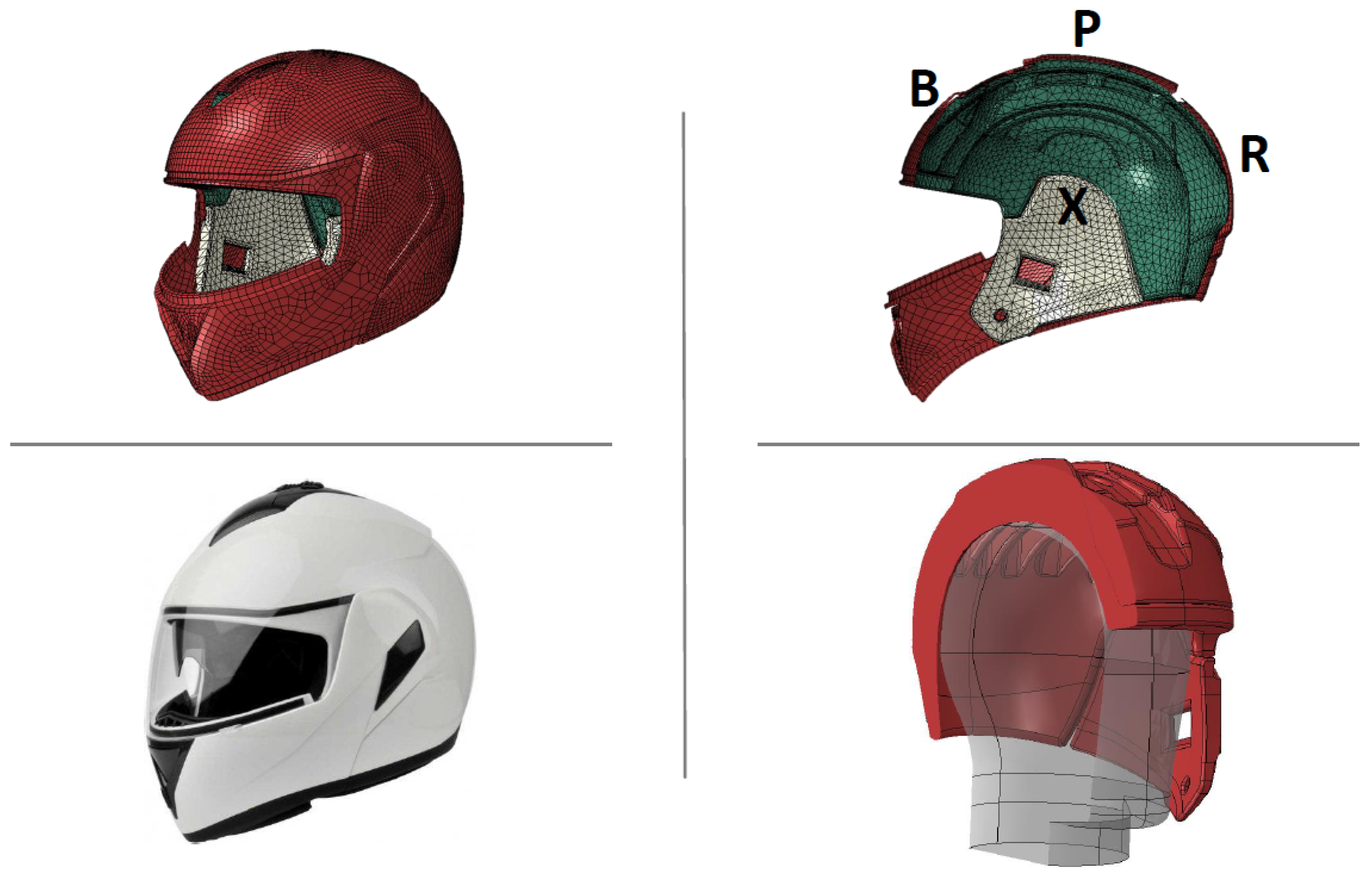
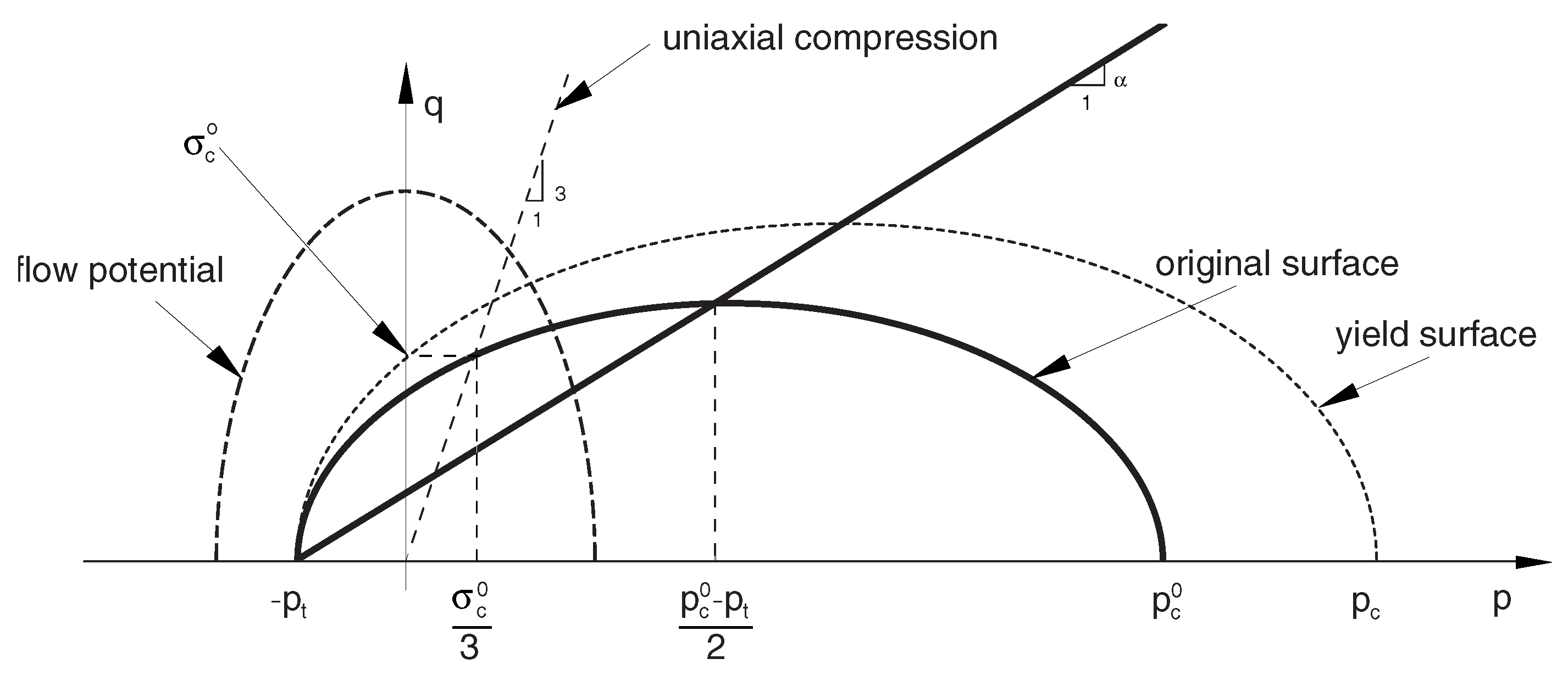
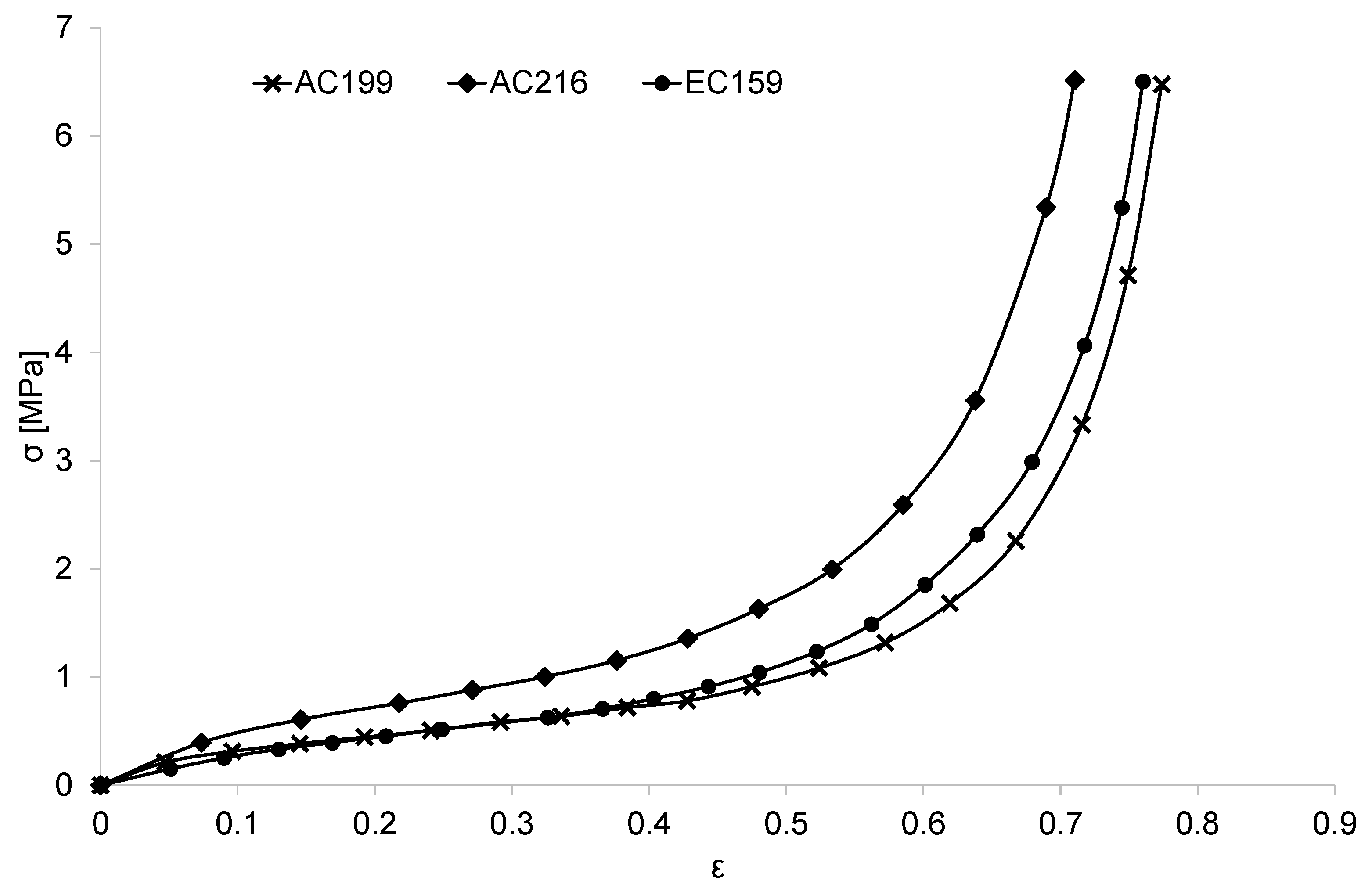
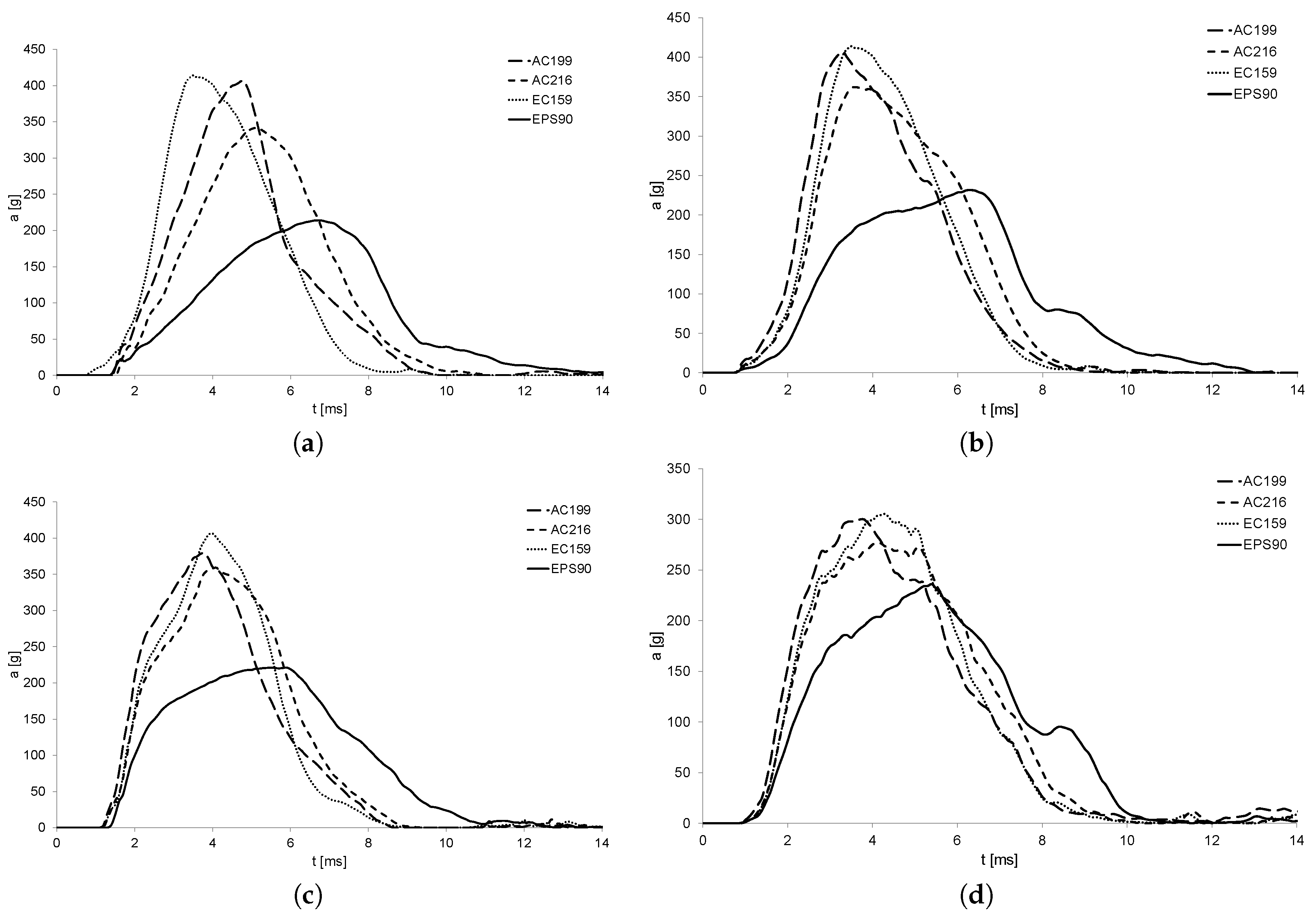
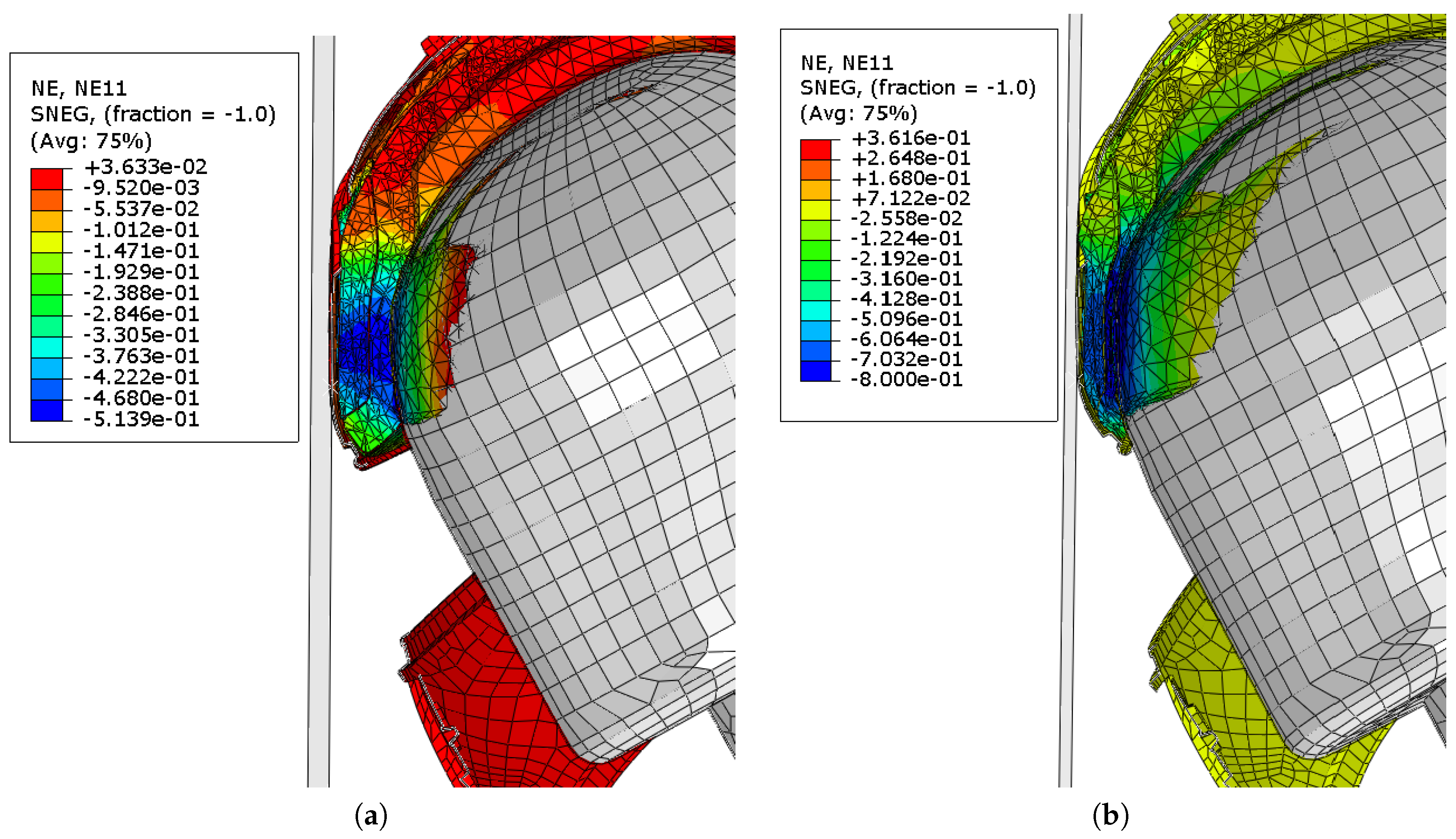
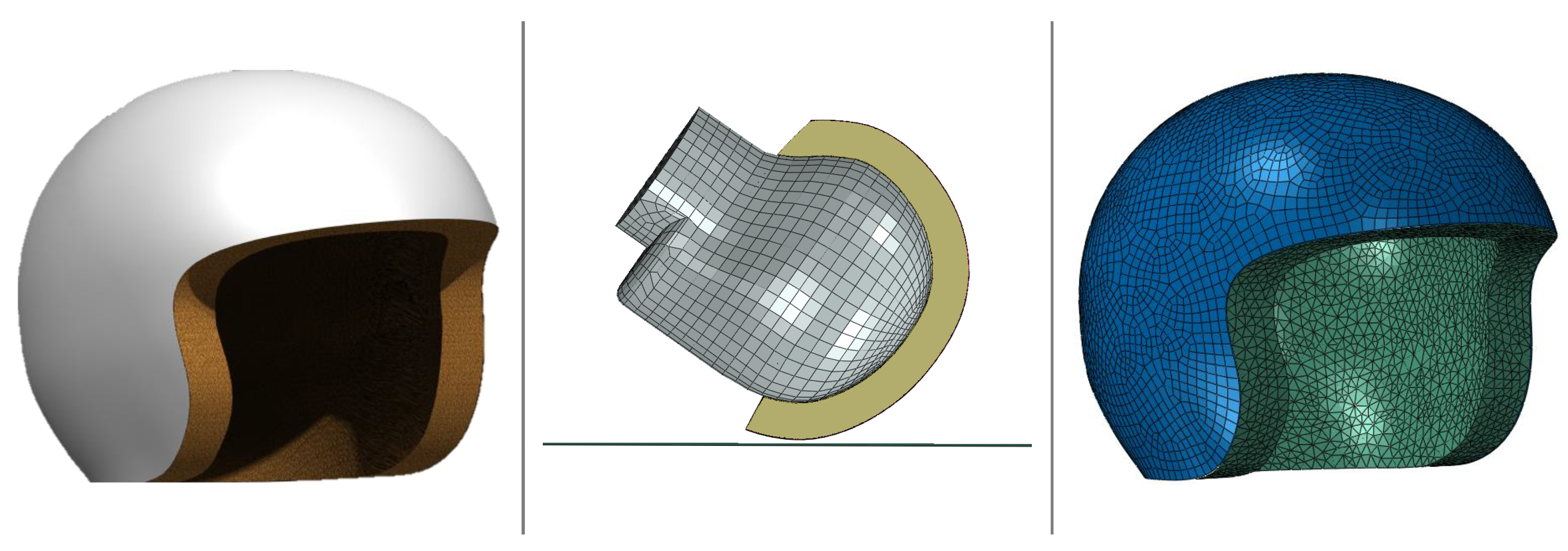
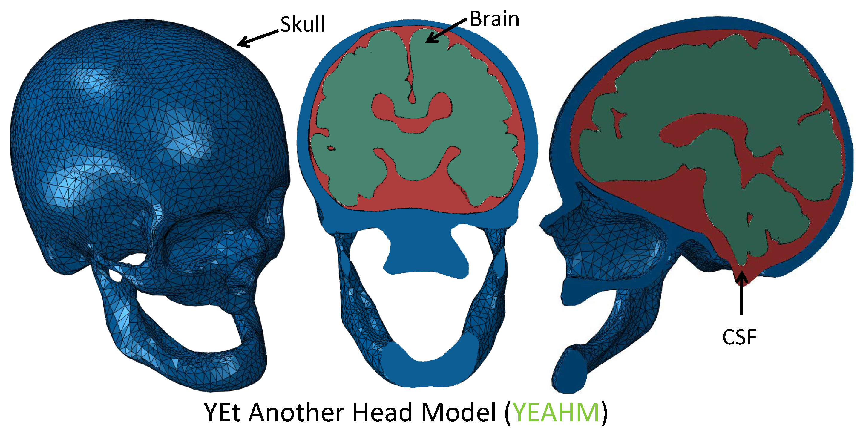
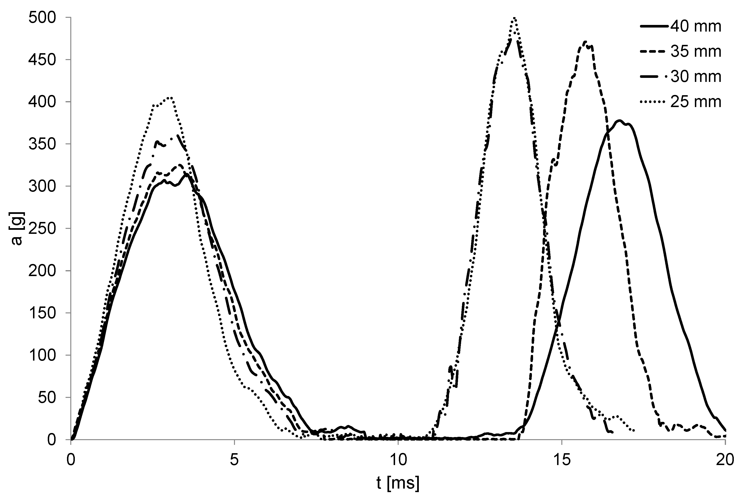
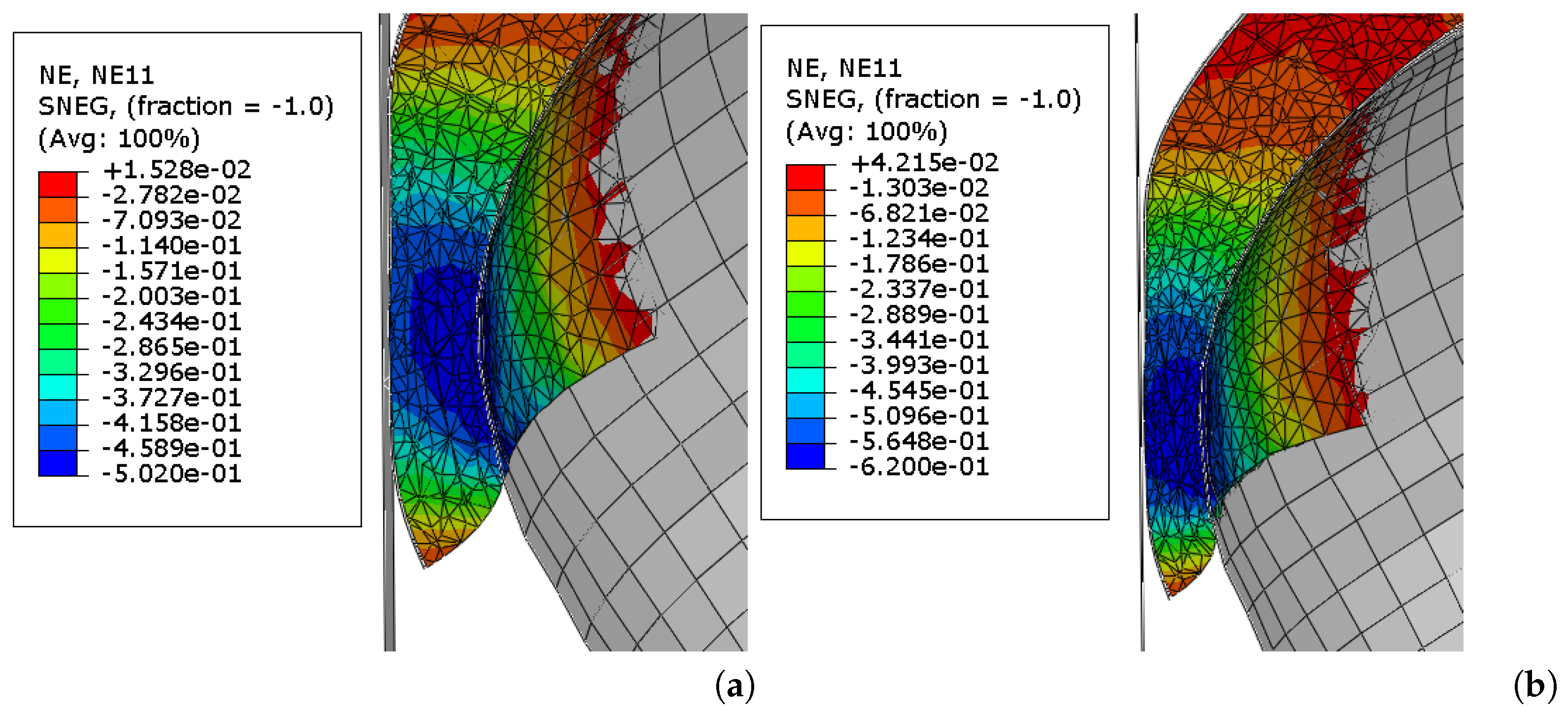
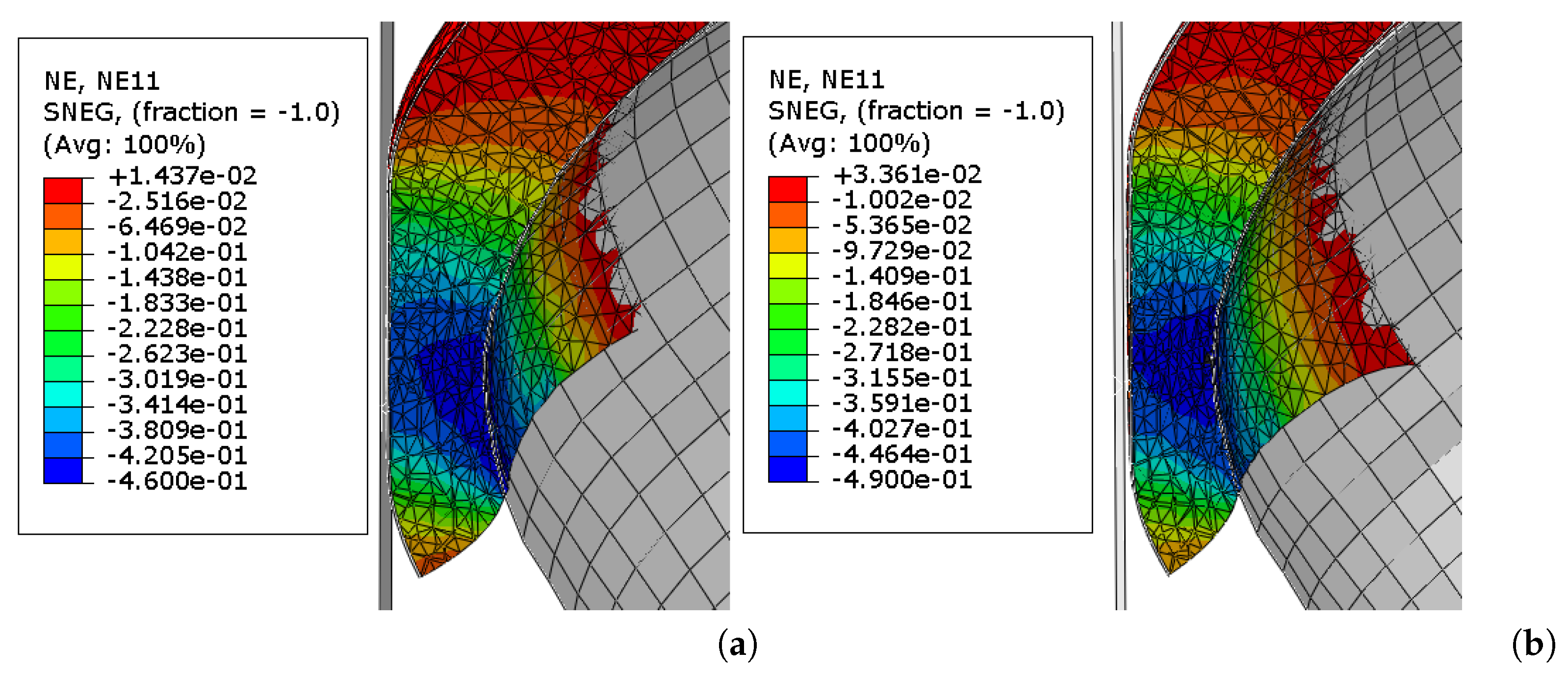
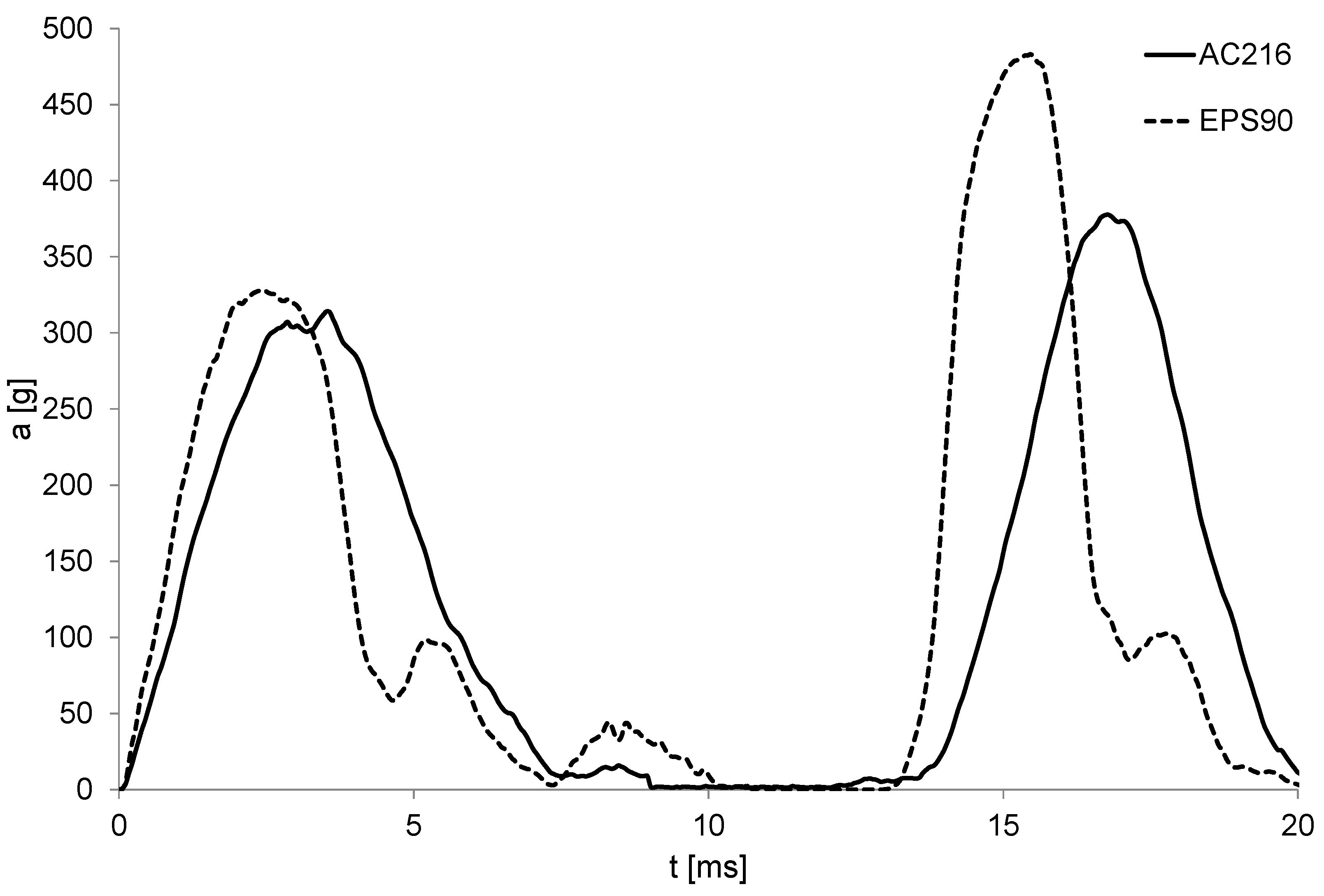
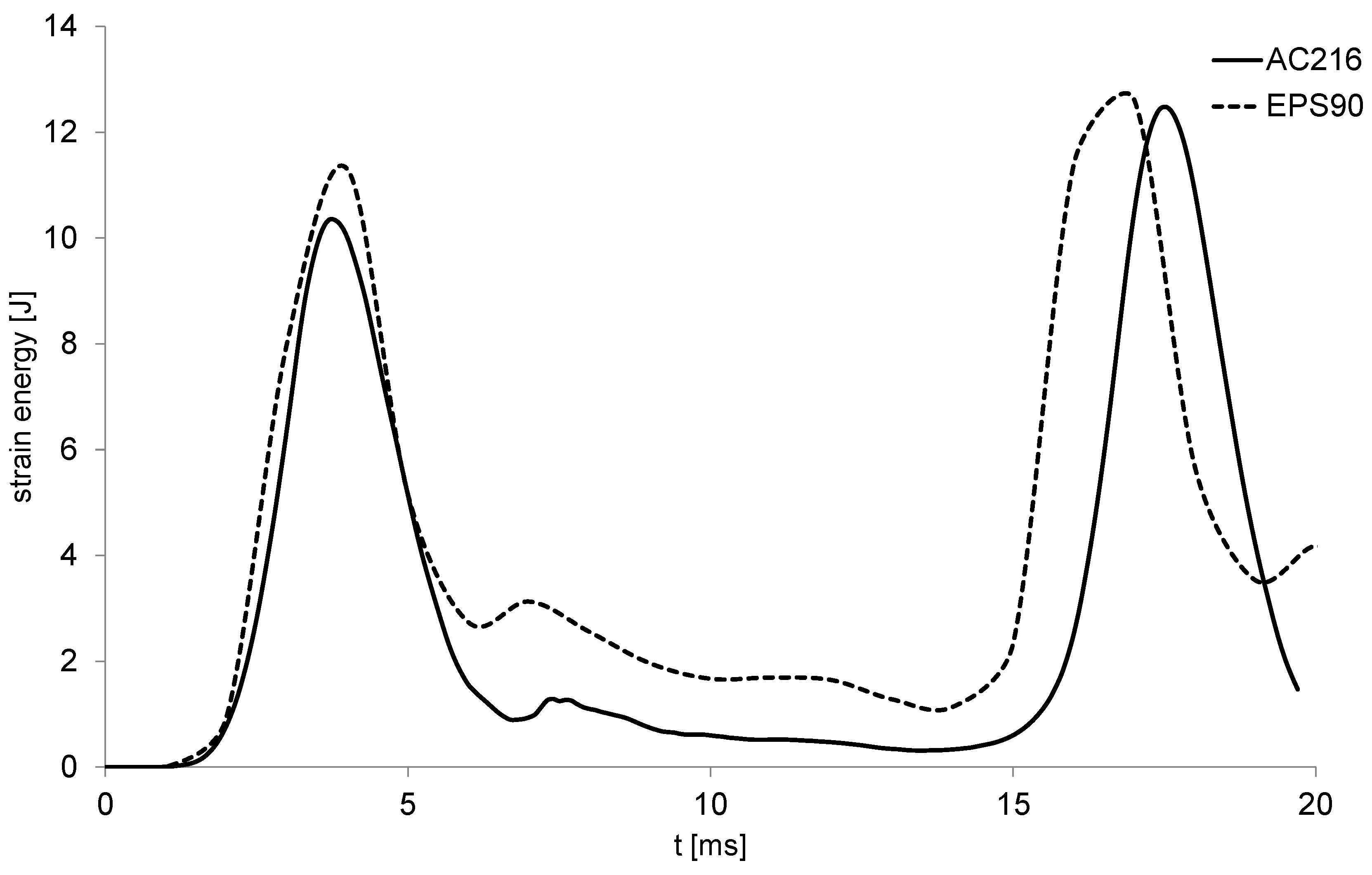
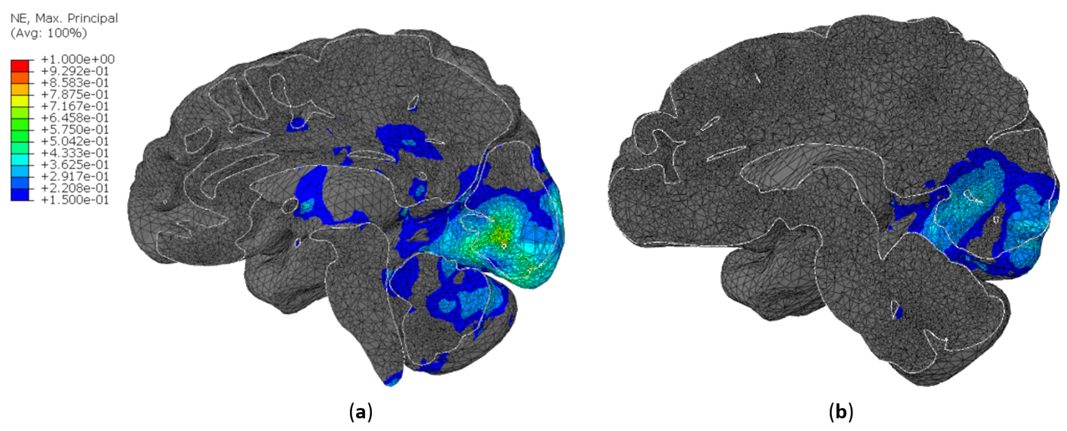
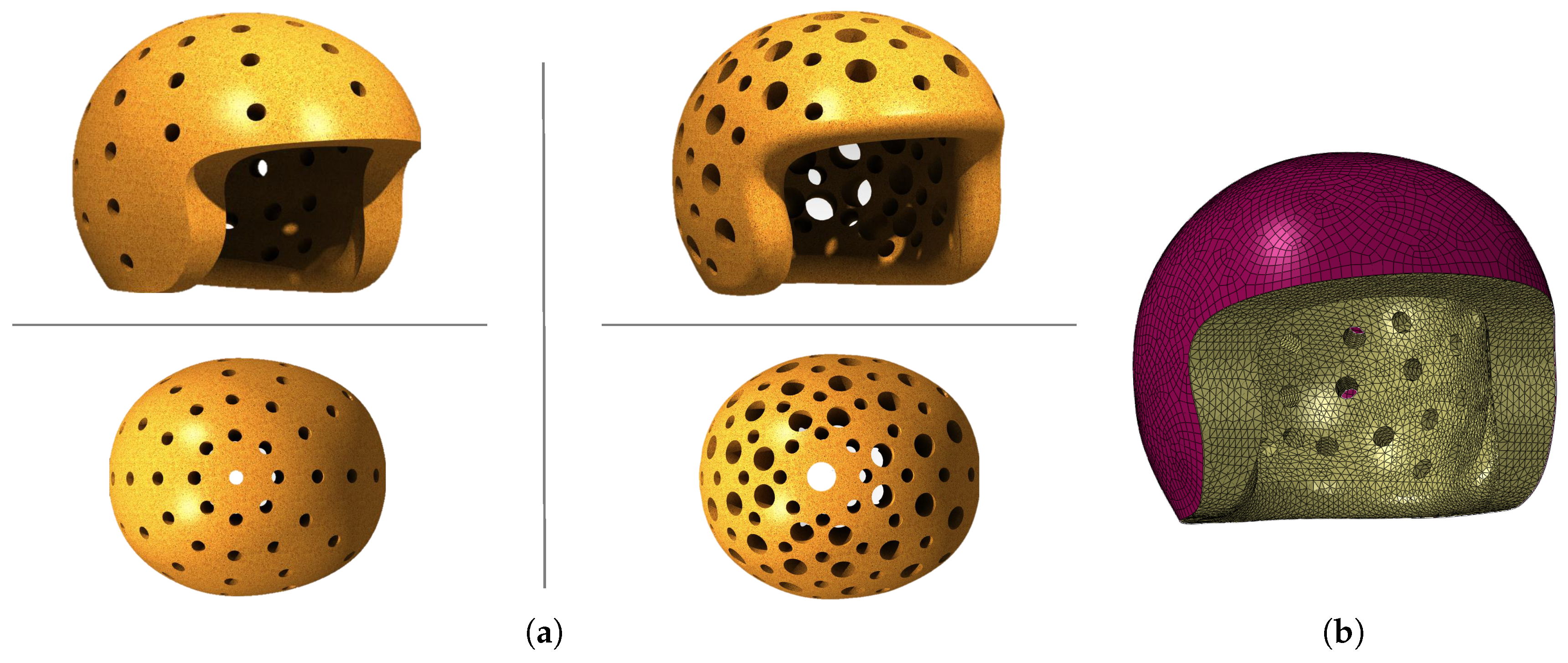
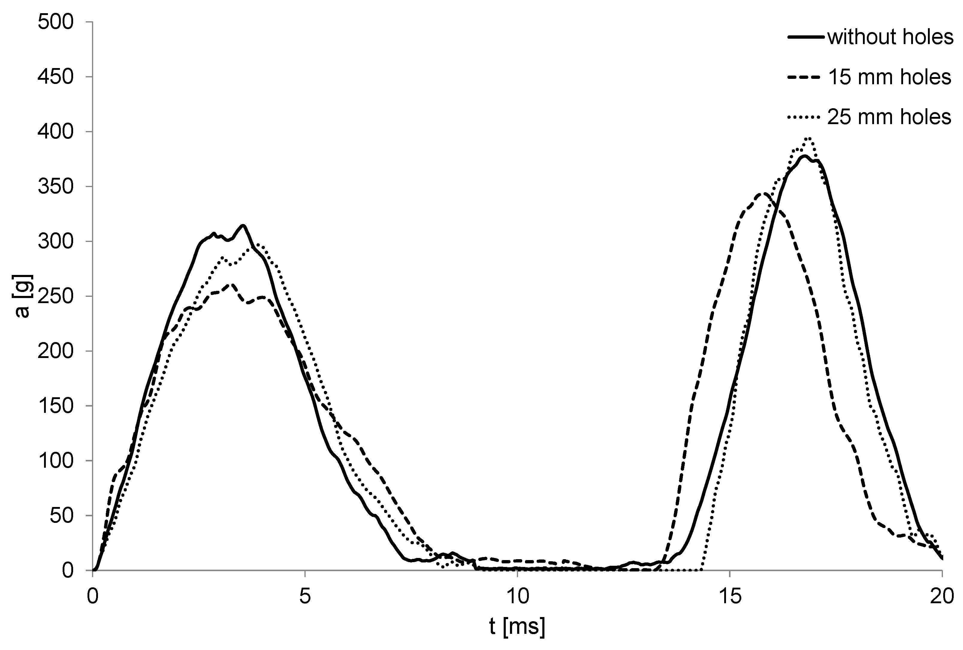
Table 1.
Material properties used as input in Abaqus material models.
| Material | [kg/m] | E [MPa] | k | r | m | |||
|---|---|---|---|---|---|---|---|---|
| AC | 199 | - | 0 | - | - | 1.8 | 0.01 | 0.1 |
| 216 | - | 0 | - | - | 1.1 | 0.5 | 0.1 | |
| EC | 159 | - | 0 | - | - | 1.01 | 0.3 | 0.1 |
| EPS | 90 | 44 | 0 | 0.1 | 2.5 | - | - | - |
| ABS | 1200 | 4000 | 0.37 | - | - | - | - | - |
Table 2.
YEAHM’s mesh info.
| Part | Number of Elements | Number of Nodes |
|---|---|---|
| Skull | 57257 | 14443 |
| CSF | 98032 | 27499 |
| Brain | 836328 | 153749 |
Table 3.
Brain material properties.
| [kg/m] | [MPa] | [MPa] | [s] | [s] | |||
|---|---|---|---|---|---|---|---|
| 1040 | 0.012 | 5.0507 | 0.04 | 0.5837 | 0.2387 | 0.02571 | 0.02570 |
Table 4.
CSF material properties.
| [kg/m ] | [MPa] | [MPa] | [MPa ] |
|---|---|---|---|
| 1000 | 0.9 | 1 | 0.9 |
Table 5.
Skull material properties.
| [kg/m ] | E [MPa] | |
|---|---|---|
| 1800 | 6000 | 0.21 |
Table 6.
Peak accelerations measured for each impact [g].
| Impact | 25 mm | 30 mm | 35 mm | 40 mm |
|---|---|---|---|---|
| First | 405.5 | 361.5 | 324.7 | 314.1 |
| Second | 499.9 | 482.2 | 470.6 | 377.7 |
Table 7.
Comparison of head injury criteria values computed for various liners thicknesses.
| Parameter | 25 mm | 30 mm | 35 mm | 40 mm |
|---|---|---|---|---|
| Strain | 0.5125 | 0.5250 | 0.4917 | 0.3833 |
| von Mises stress [kPa] | 218.7 | 204.2 | 198.8 | 134.2 |
| Pressure [kPa] | 745.8 | 823.3 | 846.7 | 691.7 |
| CSF pressure [kPa] | 482.5 | 483.7 | 434.2 | 291.7 |
| CSF strain energy [mJ] | 15506.2 | 15488.2 | 16219.8 | 12481.2 |
Table 8.
Peak accelerations measured for each liner [g].
| Impact | AC216 | EPS90 |
|---|---|---|
| First | 314.1 | 328.3 |
| Second | 377.7 | 438.1 |
Table 9.
Comparison of head injury criteria computed for helmets with AC216 and EPS90 liners.
| Criterion | EPS90 | AC216 |
|---|---|---|
| Strain | 0.5067 | 0.3833 |
| von Mises stress [kPa] | 191.7 | 134.2 |
| Pressure [kPa] | 840.9 | 691.7 |
| CSF pressure [kPa] | 459.4 | 291.7 |
| CSF strain energy [mJ] | 12611.5 | 12481.2 |
Table 10.
Total weight of each 40 mm thick liner made of AC216 [kg].
| Without Holes | 15 mm Holes | 25 mm Holes |
|---|---|---|
| 1.01 | 0.907 | 0.703 |
Table 11.
Peak accelerations measured for each AC216 liner [g].
| Impact | Without Holes | 15 mm Holes | 25 mm Holes |
|---|---|---|---|
| First | 314.1 | 260.8 | 296.8 |
| Second | 377.7 | 343.6 | 395.0 |
Table 12.
Comparison of head injury criteria computed with YEAHM for AC216 liners.
| Criterion | Without Holes | 15 mm Holes | 25 mm Holes |
|---|---|---|---|
| Strain | 0.3833 | 0.3514 | 0.5016 |
| von Mises stress [kPa] | 134.2 | 91.7 | 182.9 |
| Pressure [kPa] | 691.7 | 595.8 | 829.3 |
| CSF pressure [kPa] | 291.7 | 291.2 | 401.4 |
| CSF strain energy [mJ] | 12481.2 | 11975.9 | 19076.6 |
© 2019 by the authors. Licensee MDPI, Basel, Switzerland. This article is an open access article distributed under the terms and conditions of the Creative Commons Attribution (CC BY) license (http://creativecommons.org/licenses/by/4.0/).
Share and Cite
MDPI and ACS Style
Fernandes, F.A.O.; Alves de Sousa, R.J.; Ptak, M.; Migueis, G. Helmet Design Based on the Optimization of Biocomposite Energy-Absorbing Liners under Multi-Impact Loading. Appl. Sci. 2019, 9, 735. https://doi.org/10.3390/app9040735
AMA Style
Fernandes FAO, Alves de Sousa RJ, Ptak M, Migueis G. Helmet Design Based on the Optimization of Biocomposite Energy-Absorbing Liners under Multi-Impact Loading. Applied Sciences. 2019; 9(4):735. https://doi.org/10.3390/app9040735
Chicago/Turabian StyleFernandes, Fábio A. O., Ricardo J. Alves de Sousa, Mariusz Ptak, and Gonçalo Migueis. 2019. "Helmet Design Based on the Optimization of Biocomposite Energy-Absorbing Liners under Multi-Impact Loading" Applied Sciences 9, no. 4: 735. https://doi.org/10.3390/app9040735
Note that from the first issue of 2016, this journal uses article numbers instead of page numbers. See further details here.