Article

Improving Applicability for Information Model of an IFC-Based Steel Bridge in the Design Phase Using Functional Meanings of Bridge Components

1
Department of Civil & Environmental Engineering, Yonsei University, Seoul 03722, Korea
2
Taesung SNI Singapore, 438 Alexandra Rd., Singapore 119958, Singapore
*
Author to whom correspondence should be addressed.
Appl. Sci. 2018, 8(12), 2531; https://doi.org/10.3390/app8122531
Submission received: 6 November 2018 / Revised: 30 November 2018 / Accepted: 4 December 2018 / Published: 7 December 2018
(This article belongs to the Section Environmental Sciences)

Abstract

:
The industry foundation classes (IFC) data model is the most important data schema in ensuring the interoperability of the information generated throughout the lifecycle of facilities. However, because the current IFC model is focused on buildings, there are limitations when this model is applied to bridge structures. This paper proposes a method that enables the information modeling of steel box girder bridges based on the current IFC. To select the required and core items, we classify the components of a steel box girder bridge by the design stage with reference to engineering documents. To generate functional meanings of each bridge component, we develop the rules of the unique identifier and information reassignment, and then apply a semi-automated naming algorithm. The generated bridge information model was used to confirm the functional semantic meanings of individual components, and it was checked whether additional external information, such as carbon emissions, could be linked for specific bridge components. It was observed that information retrieval and extraction for components is possible through a semantic-based query to the generated IFC-based bridge information model.

Graphical Abstract

1. Introduction

In recent times, building information modeling (BIM) has been actively introduced in the construction industry to enhance productivity [1]. In projects involving buildings, the use of the BIM has the following advantages: (1) visibility owing to the use of a 3D model; (2) interoperability of the information owing to the use of a common data schema; and (3) persistence of the information owing to the use of a standard data schema.
The reason information interoperability should be treated as an important aspect can be explained by the problem of integration of various facilities or environmental information, or the improvement of applicability based on the information model. In the former case, the most representative case is the information linkage between BIM and the geographic information system (GIS). For example, it is essential to exchange information with the surrounding terrain of the tunnel structures. BIM does not deal with detailed information concerning the terrain or ground; it is indispensable to link it with the GIS to control the terrain information [2]. It is also essential to ensure interoperability between BIM and GIS for the construction of facilities, environmental impact assessment, resource distribution, safety analysis, or pipeline network plan [3,4]. However, as pointed out in [5], the integration of the two fields becomes compromised at the data, process, and application levels. Therefore, the authors emphasized that openness is the key to the success of the integration. The improvement of the applicability based on the information model ensures interoperability throughout the lifecycle phases or information reusability between different application fields using one model. Examples of the effort to improve interoperability using an open data schema to utilize the BIM generated in the design or construction phase are to apply the BIM in the facility management (FM) phase [6,7], or reuse it as a structural analysis model [8,9,10]. In other words, to reuse model data and ensure interoperability between software packages, the use of the information model generated based on the open standard data schema marks the beginning of the process. The industry foundation classes (IFC) is an open data schema as an international open standard developed by the buildingSMART International model support group (MSG) to support information exchange throughout the facility lifecycle [11]. Currently, the IFC4 version is the latest scheme, and most BIM authoring software packages support the IFC4-based or the IFC2 × 3-based IFC physical file format (IPFF). Therefore, the information model of a building can be based not only on the models generated using BIM authoring software, but also on the models converted to IPFF. This feature allows access to the model data not only from the software relating to the model generation but also to various software programs pertinent to the application of the model, which implies the possibility of the re-use of the model.
The successful applications of the use of the information model as a standard practice for buildings led to an increase in demand for its use in other structures as well. Consequently, there is an active effort toward the information modeling of bridge structures for productivity enhancement. However, in actual projects, bridge models are only being used as 3D digital models for visualization purposes, with the aspect of information interoperability being ignored. As an example, after the Loma Prieta earthquake, a replacement simulation using BIM was conducted for replacing the viaduct of the San Francisco-Oakland Bay Bridge [12]. However, the BIM that was actually applied to the Bay Bridge focused on virtual construction rather than the exchange of information, thus utilizing only the information regarding the geometries of the structure. The Korea Expressway Corporation attempted to build a system based on the information exchange of road structures, including bridges. They termed this the “HI-BIM” system, intending to reuse design-phase products for road structures in the construction phase using IFC [13]. Nevertheless, it could not achieve the expected results for various reasons: first, no IFC supports road structures; and, second, no specific road BIM execution plan exists. The HI-BIM system offered only some quantity-related estimation, which was derived merely from the shape models using BIM authoring software. In particular, the current situation of civil infrastructure information modeling technology can be termed as the “chasm”, as suggested by Moore [14] in the theory of the diffusion of innovations [15], or the phase immediately before or after the “trough of disillusionment”, according to Gartner’s Hype Cycle [16] representing the maturity, adoption, and social application of specific technologies.
Naney et al. [17] highlighted that the architecture, engineering, and construction (AEC) industry should build a system that obtains a standardized, valid outcome, and that can provide a visualized result of improved work efficiency to overcome the chasm faster. From the perspective of BIM, it can be said that generating an information model based on a standardized data schema is one method for creating a model in a structured and valid form. In other words, BIM data schema promotes the stabilization of technology in terms of new technology introduction, and becomes the basis for storing, discerning, and approaching information in terms of its re-usage. Björk and Penttila [18] and Cerovsek [19] suggested that the criteria for a good BIM schema are: (1) inclusion of all information about facilities; (2) coverage of all information needed by all stakeholders in all project phases; (3) non-redundancy; (4) software-independence; and (5) format-independence. Criterion (5) can be achieved with an open data schema for the generation of the information model, and Criterion (3) is related to the development of the data schema. Criteria (1) and (2) are directly related to the facility. Criterion (4) is a condition that can be satisfied using the IFC. However, elements for bridge structures have not been included in IFC since its very first release through IFC4. From an extrinsic point of view, IFC entities that represent building components, such as IfcColumn and IfcBeam, could be used as is to represent the bridge model. However, from an intrinsic perspective, certain elements are unique to bridge structures; they are not found in buildings. This implies that it is impossible to represent the functional semantic meaning of each bridge component even if a bridge model is generated using BIM authoring software and is converted to an IFC file, as noted by Lee and Kim’s research [20]. It is difficult to consider that these aspects are interoperable and software-independent. That is, to improve the usability of the bridge information model, functional semantic meanings suitable for each model component should be maintained along with a corresponding 3D model object that can be visually recognized by the end-user. In addition, based on these functional meanings, extraction of the objects and retrieval of information should be possible in a software-independent manner.
The motivation for our research is based on the need for a method that can control not only the 3D geometric information but also non-geometric attributes for an open standard-based bridge information model at present. Since the concept of the information model itself is supposed to include non-geometric information, the authors recognized the need to set up parameters for the end-user to access non-geometric information. The authors concluded that setting the parameters or unique identifiers using the functional meanings of the bridge components is consistent with the IFC concept. In this study, therefore, we propose a method to improve the usability of the IFC data schema-based bridge information model using the functional meaning of the bridge components. Section 2 discusses the consideration and analysis of the characteristics of major open data schemas for bridge structures from the perspective of applications. Section 3 describes how IFC can be applied to steel box girder bridges. In Section 3.1, the breakdown of the bridge structure is presented to select the items to identify the bridge components with reference to engineering documents such as the design drafting standard for construction, guidelines for the detailed design of steel road bridges, and bridge planning and design guide. The criteria for generating the identifiers of bridge components based on the IFC are described in Section 3.2. The criteria include the spatial arrangement of the structure and function and usage-based structural components. In Section 4, we propose a method of generating the unique identifiers of components during the process of bridge information modeling. The unique identifiers are created by referring to the functional information of bridge model components presented in Section 3. The identifiers could be stored in the IFC-based model that was built by a BIM tool through user-defined property sets (PSETs) of the IFC framework. An automated naming algorithm for identification is proposed for the objects that are recurrently arranged. In Section 5, we discuss the applicability of the proposed data schema-based bridge information model. The bridge information model was built through the proposed modeling method for an actual bridge structure. Section 5.1 shows the implemented model result. In Section 5.2, we derive the quantity take-off using the generated bridge information model and compare the result with the actual design document-based calculations. The unique identifiers based on the functional meanings described in Section 4 is used to compare the detailed quantity take-off results of the components. The applicability of the bridge information model through linkage between the information model and external information is shown in Section 5.3. We discuss the possibility of information retrieval using the unique identifiers by linking each component of the bridge model with carbon emission-related information. In Section 5.4, we examine the model applicability through object extraction, model regeneration, and knowledge derivation by using the functional meanings of the bridge components.

2. Related Works on Bridge Data Schemas

There have been studies on the development of an open bridge data schema at the research level since the 1990s, although such research for building structures began later. The most important consideration for the development of a data schema is that the data must be in a form that is accessible from any software package, while retaining a clear definition of the connections between the structure and the components. Representative examples of sophisticated data model description languages that satisfy this criterion include the EXPRESS language from Standard for the Exchange of Product model data (STEP) [21], and the Extensible Markup Language (XML) [22]; the development of bridge data schemas has been primarily based on EXPRESS or XML.

2.1. Bridge Data Schemas Using EXPRESS

2.1.1. STEP AP 203-Based Bridge Data Schema

While the Generic AEC Reference Model (GARM) of Gielingh [23] focuses on buildings, it also contains some aspects related to civil works. However, this is merely a remark that civil works are one of the AEC product types. Actual development of bridge data model based on STEP was mainly implemented during the late 1990s. During that time, the emphasis was on the representation of the geometry of the bridge using the STEP Application Protocol (AP) 203, rather than on the development of data models solely for bridges [24,25]. Halfawy et al. [26] developed an entity for a bridge information model by proposing the bridge core model (BCM), and linked this with the CIMsteel integration standards (CIS/2) [27] to allow for the management of the information for structural analysis. Moreover, Lee and Jeong [28] developed an integrated framework for a steel bridge information model using STEP AP203 and AP209. However, the BCM added and defined the entities for the elements with low-level representations, without consideration of a classification system. The BCM and the model by Lee and Jeong [28] both exclude semantic consideration of the spatial arrangement of the bridge components. As such, spatial semantic information, such as which span the bridge belongs to, must be determined from the assigned location of the physical objects, which is a difficult interpretation task for a computer.

2.1.2. IFC-Based Bridge Data Schema

IFC is also defined in EXPRESS, a model description language of the ISO-STEP. Therefore, it inherits the object-oriented programming concept of EXPRESS. As such, the model can be made more delicate and specialized by adding low-level objects through subtypes [29]. Moreover, the IFC data schema provides a basic modular structure to the information model, and a framework for the sharing of information between various areas of the construction industry. Consequently, while IFC is being developed with an emphasis on buildings, it is possible to extend the entities for application to other structures, such as bridges. Therefore, even though IFC is a schema that was developed with a focus on buildings, it is highly efficient to re-use previous IFC resources for other structures, as long as the functional role regarding which component of the bridge model it will be used for is excluded. The data schema developed by adding the necessary elements for bridges to the previous IFC resources is generally referred to as an IFC-Bridge, of which the representative examples are the works of Arthaud and Lebegue [30] and Yabuki et al. [31], which are based on the IFC2X2 version While these two research teams initially worked independently of each other, they integrated their two data schemas after recognizing the similarity between their works. The integrated schema addresses both the physical and the spatial elements of a bridge, unlike the data schema discussed in Section 2.1.1. To represent the information about the physical function of the bridge components, IfcBridgePrismaticElement, IfcBridgeSegment, IfcBridgeElementComponent, and their subtypes are additionally defined as the subtypes of the existing IFC entity, IfcElement. To represent the spatial meaning of a bridge, IfcBridge and IfcBridgeStructureElement are added as subtypes of the existing IFC entity, IfcSpatialStructureElement. Horizontal alignment of the bridge is addressed by adding the entity IfcBridgeReferenceLine, which has the previous IfcCurve resource as an attribute.
Lee and Kim [20] proposed an IFC extension model for road structures, which includes bridges as a sublevel structure. Lee and Kim’s [20] bridge model is characterized by the inclusion of items for the management of spatial arrangement information of the bridge members and the start/end point information of the horizontal road alignment, as compared with the previously mentioned IFC-Bridge schema. An element for the road space, IfcSpatialRoadElement, is additionally defined as a subtype of the existing entity, IfcSpatialElement, which also includes the subtypes of IfcBridge, IfcBridgeSpan, and IfcLane (common items used in road elements). The model allows for the identification of elements that are arranged in the parallel and vertical directions to the bridge span using these subtypes. The start/end point of the horizontal road alignment is managed as an attribute of the IfcGlobalPointReference (extended entity) type in IfcSpatialRoadElement. However, ultimately, additional entities and attributes must be developed, corresponding to the inclusion of all information about bridge structures. However, as noted by research of Lee et al. [32], the advantages of BIM from the sharing and re-use of information cannot be acquired at all, unless a modeling software package that supports the changed schema is developed and popularized.

2.1.3. Bridge Schema Elements in IFC

While the 2013 release of IFC4 contains the necessary entities for buildings only, it does include basic high-level elements for the enhancement of the support for other infrastructures in the future. These include IfcCivilElement and IfcCivilElementType, which were added as subtypes of IfcElement and IfcElementType, respectively. To develop the subtypes, attributes, and PSETs for these elements, buildingSMART International (bSI) founded the Infrastructure Room [33], which is now developing the standards for alignments [34,35], roads [36], and railways [37]. These will be included in IFC5 and it is known that the bridge schema is included in the Road and Railway Extension Project. However, as expressed by Cerovsek [19], even if a new schema were to be released, there would be a significant delay before its implementation in software: it was not until more than 10 years after the development of IFC that many BIM authoring software packages started to support IFC officially. Therefore, even if the elements pertinent to bridges were to be added to IFC, it is predicted that it would take a long time to generate information models, and to utilize them in actual applications effectively. This characteristic can be said to be an environment that cannot appropriately respond to the present demands of the user for the re-use of information and the efficiency enhancement of information management during a bridge lifecycle.

2.2. Bridge Data Schemas Using XML

2.2.1. Bridge Data Schema in CityGML

CityGML is an open data schema suggested by the Open Geospatial Consortium (OGC) as a standard for the representation, storage, and exchange of city information. CityGML established the schema by adopting separate modules for each of the facilities that form a city [38]. While the initial version did not include bridges, version 2.0, released in 2012, includes a bridge module, which is a data schema for bridge structures [39].
Similar to IFC-Bridge, the bridge module of CityGML also distinguishes spatial and physical objects. Functional information can be assigned to a physical object using the BridgeConstructionElement or BridgeInstallation. While spatial objects are not explicitly instantiated in CityGML, spatial information can be represented using the BridgePart element. Moreover, the difference between CityGML and the previously mentioned STEP-based bridge schema is that the CityGML bridge module also comprises four stages of the level of detail (LoD), directly inheriting the characteristics of CityGML. While the representation of horizontal alignment is not included in CityGML as an explicit item, it can be implemented using the lod0Network, which is included in the transportation modules, and the CompositeCurve elements. However, as previously discussed, the bridge module of CityGML does not include the items needed for identification of the spatial arrangement of bridge components, and the application is difficult to use due to the lack of modeling software packages that directly support CityGML.

2.2.2. Bridge Data Schema in TransXML

TransXML is an open data schema developed by the NCHRP project of the US National Research Council for the exchange of transportation data of the public sector [40]. TransXML specifies and focuses on four business areas, including “highway bridge structures”. The difference in the bridges in TransXML to those in the other already mentioned data schemas is that the TransXML version contains detailed elements for structural analysis and design, along with a general description of the bridge. (While this can be said to be similar to the Structural Analysis Domain and Structural Elements Domain of the “domain layer” in IFC, TransXML is specialized for highway bridges, unlike IFC.) However, the TransXML bridge does not consider explicit elements for the representation of the geometry of the model. While it provides elements for the geometry of the members of the entire bridge (Bridge > BeamShapes and its subelements), it is impossible to identify the meaning of the bridge components based on geometry. Therefore, the applications of TansXML adopt the geography markup language (GML) of OGC as a common framework. However, there are inevitable problems, since the TransXML bridge focused on engineering design while GML was developed for the geospatial domain.
Based on the previous discussion, the following criteria were adopted as important considerations for the selection of a bridge data schema for use in this study.
  • Interoperable and accessible: The schema must be software-independent, and the model data should be accessible in any situation
  • Three-dimensional: The schema must be able to manage the information of the constituent elements of the bridge based on 3D geometry
  • Semantic: The schema must include functional semantic information of the bridge components, and be capable of spatially and physically distinguishing the components
  • Software-based data manageable: The schema must allow information modeling on BIM authoring software
As mentioned in Section 1, IFC is the ISO standard for BIM, satisfies all of the above criteria when applied to buildings, and is supported by an increasing number of BIM software packages. Moreover, there is a clear likelihood of extending IFC to structures other than buildings, similar to the aforementioned work of the Infrastructure Room. Accordingly, we state that the bridge information model in this study was created based on IFC4, which is the latest official version released, and explain its scope of application.

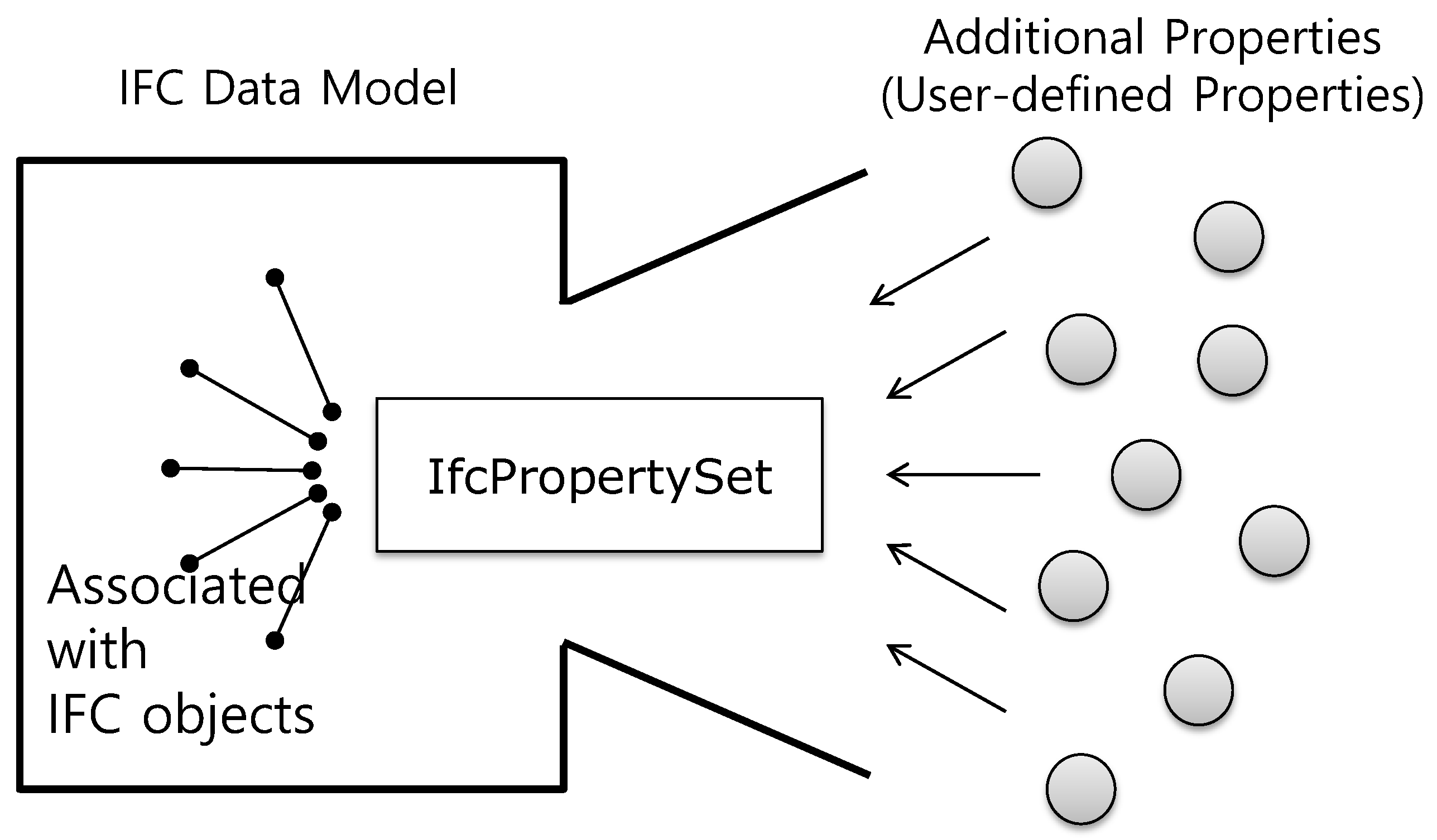
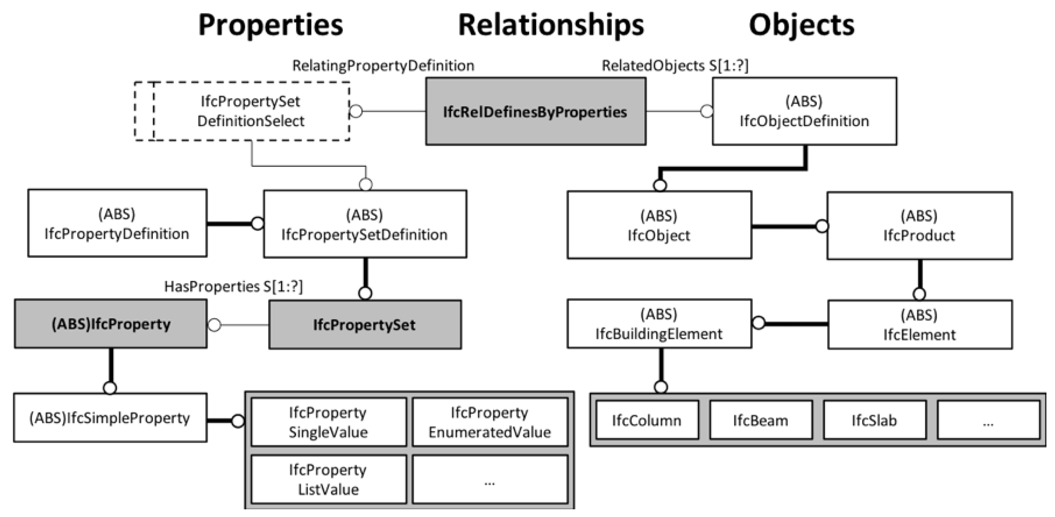
2.3. User-Defined Property Sets at a Glance

IFC contains various entities and PSETs for the exchange of information about a building during its lifecycle. However, it cannot satisfy all the requirements necessitated by structures such as buildings or bridges [41]. While this can be resolved, as mentioned above, by establishing a new data schema through the extension of entities, IFC also internally supports extension through PSETs [42]. IFC PSETs are generated as references to external data, unlike the addition of entities, and hence do not modify the IFC schema (see Figure 1). As such, the extended data schema can be directly utilized in all BIM authoring software packages that support IFC.
The most critical reason for the inability to properly utilize IFC as a bridge data schema is the difficulty in representing the functional meaning of the constituent elements of a bridge [20]. Therefore, in this study, we define the necessary additional elements for the management of the functional semantic information of bridge components using “IFC user-defined PSETs”.
The user-defined PSETs of IFC can be represented using a container class, IfcPropertySet. To effectively represent the user-defined PSETs during this process, at the data schema level, IfcPropertySet only defines the types of dynamic metadata. Figure 2 shows the relationships between objects focused on IfcPropertySet, which can be used in applications through the following criteria.
  • IfcObject is used as it is for the objects that represent the components themselves. During this process, IfcPropertySet and IfcObject can be linked by IfcRelDefinesByProperties, a subtype of IfcRelationship.
  • The properties that form IfcPropertySet are represented using IfcProperty, an entity that implements “HasProperties”, an explicit attribute of IfcPropertySet.
  • The semantic meaning of a property is defined through the explicit “Name” attribute of IfcProperty.
  • A user-defined property is represented using IfcPropertyBoundedValue, IfcPropertyEnumeratedValue, IfcPropertyListValue, IfcPropertyReferenceValue, IfcPropertySingleValue, and IfcPropertyTableValue, all of which are subtypes of IfcProperty.
In summary, the information, set by users in advance, is identified through IfcProperty, and appears as instances through the subtype of IfcProperty. Although this is an auxiliary method for creating a bridge model using the IFC4 shown in Table 1, there is an advantage in that it can be utilized to create and manage the functionalities of the elements used in the construction of the bridge.

3. IFC Extension Using User-Defined Property Sets for Steel Box Girder Bridges

3.1. Required Information for a Steel Bridge Data Schema

The classification of the structural elements of a steel box girder bridge is needed for the semantic and functional identification of each element. This is closely related to information generated during the bridge design phase. In particular, information modeling is the process of completing the model by adding relevant nongeometric information to the 3D geometry, and geometric representation can be said to be important for this process. Therefore, in this study, bridge components used for the design phase were analyzed, and the results were utilized as the basic elements for the development of the data model. Since the information generated during the design phase encompasses most of the information required during the bridge lifecycle, the element analysis in this study was restricted to the design phase. During the analysis, the design drafting standard for construction established by Ministry of Land, Transport and Maritime Affairs of Korea [43] was consulted for a list of the tasks completed during the design phase.
The primary task accomplished during the fundamental planning phase is selecting and specifying the optimal route. Therefore, the steel box girder bridge information model for the support of the fundamental planning phase is a conceptual representation of the route. During the fundamental design phase, the location and type of the bridge are determined. Consequently, to support the fundamental design phase, the modeling must be conducted to the extent of being able to identify the length of the model elements, and the bridge width, location, and direction.
The objective of the detailed design phase is to compile the drawings and specifications necessary for the actual construction, by concretizing the fundamental design. Therefore, all of the components from the fundamental design are included, and, in addition, each element must be represented in greater detail. “Guidelines for the Detailed Design of Steel Road Bridges” [44] and “Bridge Planning and Design” [45] were consulted for the classification of the specific components for each level of representation of the model, which were defined for each of the three phases of fundamental planning, fundamental design, and detailed design. The corresponding results used in this study are shown in Table 2. The breakdown of the structural items that comprise the steel bridge are listed in Table 2 and the table can be used to identify the function of each item.

3.2. IFC-Based Semantic Meanings for the Components of a Steel Box Girder Bridge

To ensure the compatibility of the elements of the information model between different software packages while including semantic information, measures for the management of semantic meaning at the data schema level must be established. In this study, functional semantic information of the bridge components was generated using IFC user-defined PSETs. Storage of the semantic information of the bridge components in PSETs, and how the PSETs are composed, are important considerations. In this study, the configuration of bridge entities was based on the work of Kim and Lee’s research [46], according to which building and bridge models differ in terms of the spatial arrangement of the model, and the function of the elements that form the model. Therefore, the user-defined PSETs in this study were primarily composed of the following contents.
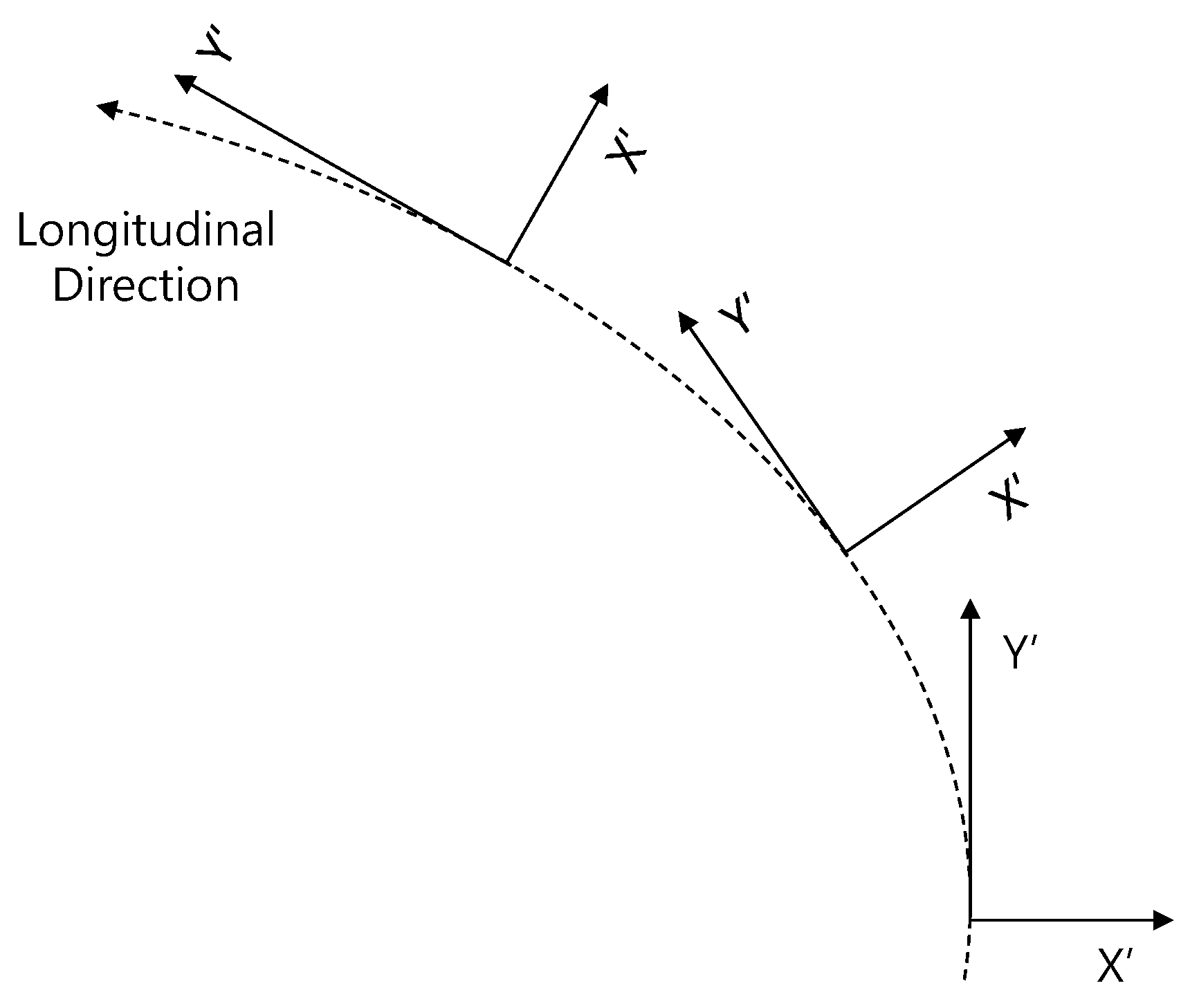
  • Identification of the spatial arrangement of the structure: In building structures, space is extended vertically within the known range of the limited site. In contrast, in bridge structures, in addition to the vertical spatial arrangement of components with different functions, the arrangement of similar (or identical) elements in the spanwise direction is a highly important aspect. This affects not only the bridge structure, but also equally affects the road and tunnel structures that form the road system. Therefore, this study focused on enabling the identification of the spatial arrangement of each bridge component using its properties, rather than the alignment of the entire bridge. The advantage of this method is that the spatial identification method can be used unchanged, even if a new entity for alignment is added at a higher level of IFC.
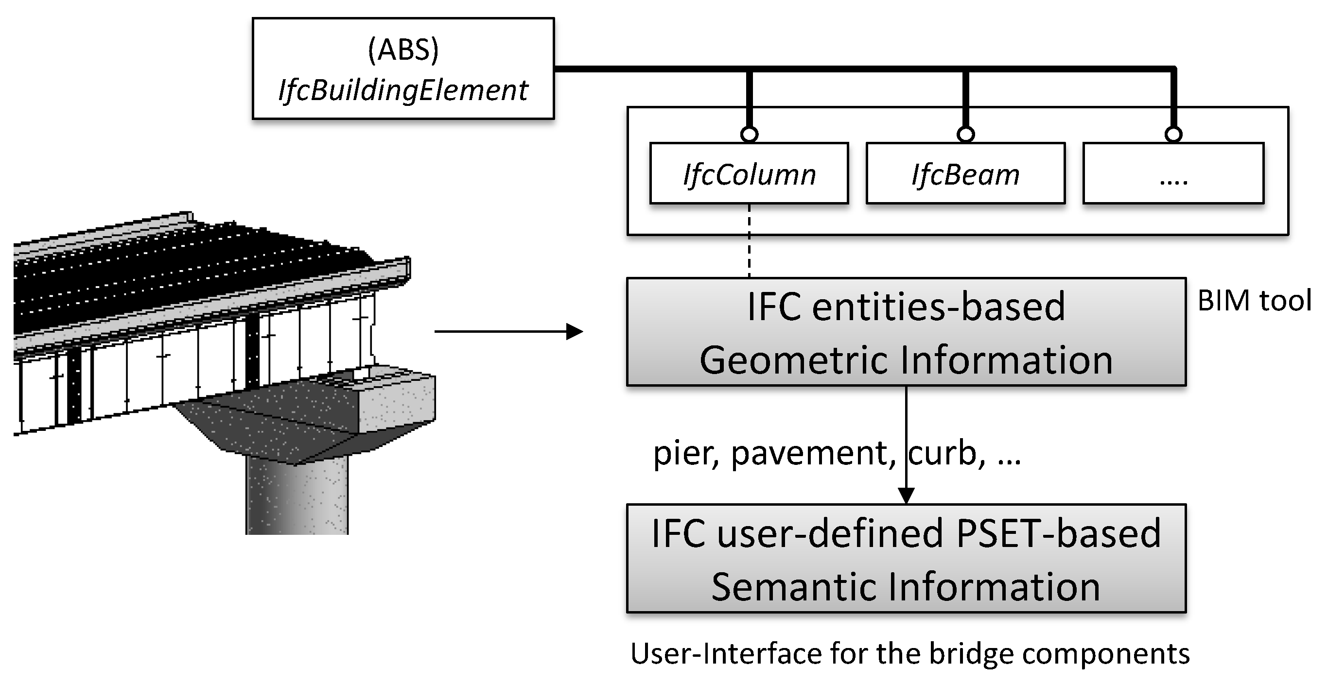
  • Identification of the structural components based on function and usage: Considering the aspect of structure, buildings and bridges can share most of the resources. IFC distinguishes such entities or types in the Resource Layer. The Resource Layer includes elements such as geometry and material, which do not have functional meaning. The physical aspect of the functional meaning of building components is handled by entities that belong to the IfcSharedBldgElements schema that are represented in the IFC physical file (IPF) through subtypes of the IfcBuildingElement entity. Therefore, for bridge information modeling, the function and usage must be represented similarly to those represented by the subtypes of the IfcBuildingElement.
The identification of the spatial arrangement of bridge components in this study relates to the location, region, and topology of the component. For buildings, a single story is considered as the largest unit object, and the space of the repeated stories of a building is managed by IfcBuildingStorey and its subtypes. However, as mentioned earlier, this only considers the direction vertical to the ground (while, indeed, the elements for the interior space of each floor are identified for buildings, these are low-level elements for the spatial identification of a floor, and are thus considered out of the scope of this paper). In contrast, for bridges, a spatial definition for three directions is required, even if the largest functional unit object is set as the reference (see Figure 3).
In the Z-direction, the classification of the super/substructure of the bridge was assigned as the basic property. Although it is not considered in this study, a bridge pier can also be classified in terms of the Z-direction for spatial identification that includes the pier for bridge information modeling. The Y′-direction is the direction tangential to the spanwise direction of the bridge, and indicates the spanwise direction of the bridge. The X′-direction is the direction that is perpendicular to the Y′-direction, in a plane that includes the Y′-direction. As such, in this study, the spaces corresponding to the Z-, Y′-, and X′-directions were identified using the Structural System, Span, and Girder properties, respectively (see Figure 4).
In this study, the physical semantic identification of bridge model elements is the determination of what function the element has, and what the usage of the element in the bridge is. For buildings, this is addressed by the IfcSharedBldgElements schema of IFC. IFC defines each entity with reference to ISO 6707-1 [47]. While some of these elements can be used directly for bridge structures, it is difficult for other elements to convey the function or usage in bridge models. For example, IfcDoor is defined as “a building element that is predominately used to provide controlled access for people and goods” in the IFC data schema. Here, if the higher-level object of “a building element” that contains IfcDoor is excluded, there is no functional difference even when IfcDoor is directly applied to bridge structures (e.g., the door inside a bridge for bridge maintenance). However, there are difficulties in directly applying IfcColumn to bridge piers, although both columns and piers are structural members that transmit the compressive forces applied to them to their bases.
  • In supporting dynamic loads, a pier is largely affected by the dynamic load in the direction vertical to the ground, while a column is affected by the dynamic load in the direction parallel to the ground.
  • In terms of general functional classification, a column is a necessary condition for a pier (i.e., pier ⊂ column).
  • In terms of usage, the column of a bridge substructure is termed separately from a pier.
Therefore, in this study, the physical elements were identified in a way that directly supports the entry of the classification of steel box girder bridge components. This allows classification of steel bridge components into parts and assembly, depending on the level. In this study, the physical components of a steel box girder bridge were also classified into Part, the single part property, and Assembly, the assembled product property, and assembled products were further classified into the combination of single parts (Parts Assembly) and the combination of assemblies (Assembled Assembly) (see Figure 5). Here, single parts refer to the components that are represented when a steel box girder bridge model is described in greatest detail. Moreover, the items for the smallest unit and combination were as shown in Table 2. In the case there are items that have not been included in Table 2, the model creator can create extra identification names, which would be applied in the IFC model as it is.
Table 3 shows the IFC user-defined PSETs proposed in this study for the abovementioned context. This consists of the attributes for the generation of spatial meaning, namely Structural System, Span, and Girder; the attributes for the generation of physical meaning, namely Assembled Assembly, Parts Assembly, and Part; and the attributes for the basic information of the model, namely Project Stage, Model Element Author, and Description.

4. Naming Process for Bridge Components

The most significant advantage of the application of the IFC user-defined PSETs proposed in this study is that it enables direct modeling of the IFC-based bridge information using the current BIM authoring software that supports IFC.
The generation of the semantic information of the components of an actual bridge consists of the following two stages. The first stage is the generation of the information regarding the usage and function of the component in question, among other components. The second stage is the assignment of a unique identifier between multiple instances of the same component. As such, two stages of the IFC-based bridge modeling process are proposed in this study.
The first stage is that in which the user generates the semantic identification information of the component with reference to Table 2 during bridge modeling. The second stage is the process of generating the identifiers for the identified components, in accordance with their relative locations. Pset_SteelBoxBridgeComponentsIdentification (see Section 3) applies the information generated through the above two processes.

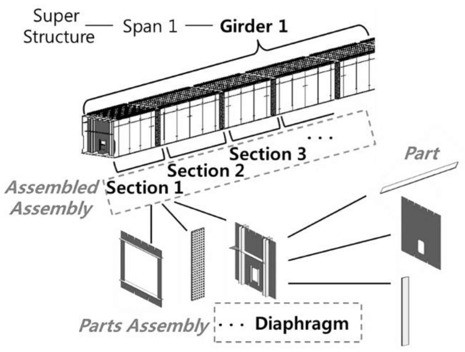
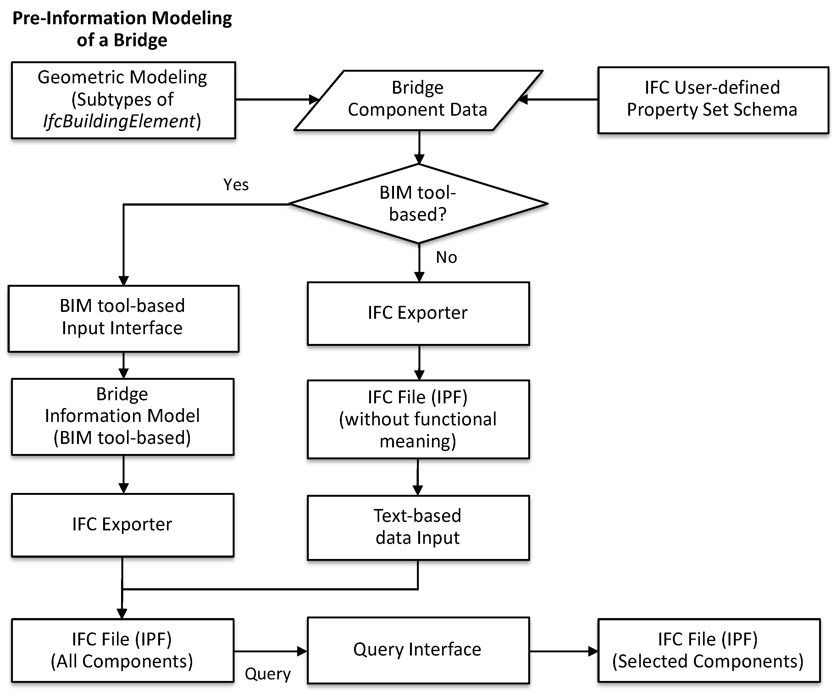
4.1. Basic Bridge Geometric Modeling and Information Reassigning

Figure 6 shows a conceptualization of bridge information modeling through current BIM authoring software. For bridge information modeling, the following processes were performed: (1) geometric modeling of the bridge structure; and (2) reassignment of the semantic information by modeler. The geometric model was built using the BIM authoring software that supports the IFC data schema. That means that the components of bridge structure were modeled through specific IFC entities of building structure—the subtypes of IfcBuildingElement. In this study, the geometric modeling was performed through IfcColumn of IFC entity in the case of the bridge pier model. The functional meanings, user’s intentions for identifying the components of the bridge model are integrated with the subtypes of IfcBuildingElement using user-defined PSETs.
Figure 7 shows the specific process for the IFC-based bridge information modeling using the BIM authoring software. Pre-information model in Figure 7 means a geometric model was built by BIM authoring software. Bridge component data in Figure 7 can refer to the component items in Table 2. The identifiers of the model components of the bridge were generated through the user-defined PSETs defined in accordance with Section 3.2 and Table 3. We propose two methods to reassign the functional meanings of the bridge components to the existing bridge geometric model. The first method utilizes BIM authoring software, which builds a geometric model. In this study, we developed a user interface (UI) for managing the information using Autodesk Revit API (see Figure 8). To control the nullable type, the UI uses a checkbox to determine whether the information for Girder, Assembled Assembly, and Parts Assembly need to be entered. The IFC-based bridge information model intended in this study was built through the integration of geometric model and semantic identifiers. The IPF of the bridge model can be created by the IFC exporter of Revit software.
The second way to reassign the functional meanings of bridge components is to input them directly into the generated IPF. This method, however, suffers from a disadvantage: the end-user cannot check the geometry of the object to reassign information simultaneously. However, it is software-independent, and the speed of information generation is fast. This speed is an important factor for facilities with many objects, such as bridge structures. The globally unique identifier (GUID) of the object, which is automatically generated in the IFC parsing step, and the data for reassignment, are both required. Algorithm 1 shows the process of adding newly defined user-defined PSET data to an object in the IPF generated in this study. The input data for Algorithm 1 are a list of the name and value data of the property to be added to the IPF, the GUID of the IFC entity, and the instance of the “Population” class, which has the same structure of the schema as the generated IPF. In this study, the “Population” of the generated IPF was compiled using ST-Developer from STEP Tools, Inc. To process multiple PSETs, a “DO” loop was applied (Line 2). The relatedObject (Line 3) is the same as “RelatedObjects” in Figure 2 and represents the object to which PSET is connected. The relatedObject can be retrieved through the inputted GUID. Lines 7–12 show the steps for creating entities and attributes of IfcPropertySet and create related information about IfcProperty using Lines 15–23. The generated data are linked with IfcPropertySet via Line 24. The connection between the object and the property shown in Figure 2 is implemented through the createRelationship function, which refers to the creation of a relationship entity (Line 30) and the connection of the object (Lines 32–35) through the assignment of its attributes.
Algorithm 1. Algorithm for creating the user-defined PSETs data in existing the IPF.
Input 1: psetListNode - XML nodes type of Pset_SteelBoxBridgeComponentIdentification property set including name and value data of property.
Input 2: GUID of an object - string type
Input 3: Population of generated IFC file - schemaParser.Population type
Output: Creating the Pset_SteelBoxBridgeComponentIdentification related entities
1 NodeList psetListNode
2 do (Node pset : end of psets)
3   relatedObject in Figure 2: IFC entity correlated to the GUID
4   psetGuid: new GUID of ifcPropertySet
5   psetName: getting property set name from the pset
7   Ifcpropertyset in Figure 2: IfcPropertySet class for inclusion in Population
9   //setting the IfcPropertySet attributes to the Ifcpropertyset class
10   Ifcpropertyset.setGlobalid(psetGuid)
11   Ifcpropertyset.setOwnerhistory(getIfcOwnerHistoryInPopulation(ref Population))
12   Ifcpropertyset.setName(psetName)
13   SetIfcproperty: set of IfcProperty in Figure 2
14   NodeList properties: properties included in the pset
15   do (Node property : end of properties)
16    propertyName: getting a property name from the property
17    propertyValue: getting a property value from property
18    Ifcpropertyvalue that subtypes of IfcSimpleProperty in Figure 2: IfcPropertyValue class for inclusion in Population
19    //setting the IfcPropertyValue attributes to the Ifcpropertyvalue class
20    Ifcpropertyvalue.setName(propertyName)
21    Ifcpropertyvalue.setNominalvalue(propertyValue)
22    SetIfcProperty.add(Ifcpropertyvalue): adding the Ifcpropertyvalue to SetIfcProperty class
23  end do
24  Ifcpropertyset.setHasproperties(SetIfcProperty): setting the HasProperties attribute in Figure 2
25  createRelationship(relatedObject, Ifcpropertyset): creating the relationship entity
26 end do

Function createRelationship(relatedObject, Ifcpropertyset)
27 SetIfcobjectdefinition: set of IfcObjectDefinition in Figure 2
28 SetIfcobjectdefinition.add(relatedObject): adding the relatedObject to SetIfcobjectdefinition class
29 Ifcpropertysetdefinitionselect in Figure 2: IfcPropertySetDefinitionSelect class for inclusion in Population
30 Ifcreldefinesbyproperties in Figure 2: IfcRelDefinesByProperties class for inclusion in Population
31 //setting the IfcRelDefinesByProperties attributes to the Ifcreldefinesbyproperties class
32 Ifcreldefinesbyproperties.setGlobalid(new GUID)
33 Ifcreldefinesbyproperties.setOwnerhistory(gettingIfcOwnerHistoryInPop(ref Population))
34 Ifcreldefinesbyproperties.setRelatedobjects(SetIfcobjectdefinition)
35 Ifcreldefinesbyproperties.setRelatingpropertydefinition(Ifcpropertysetdefinitionselect)

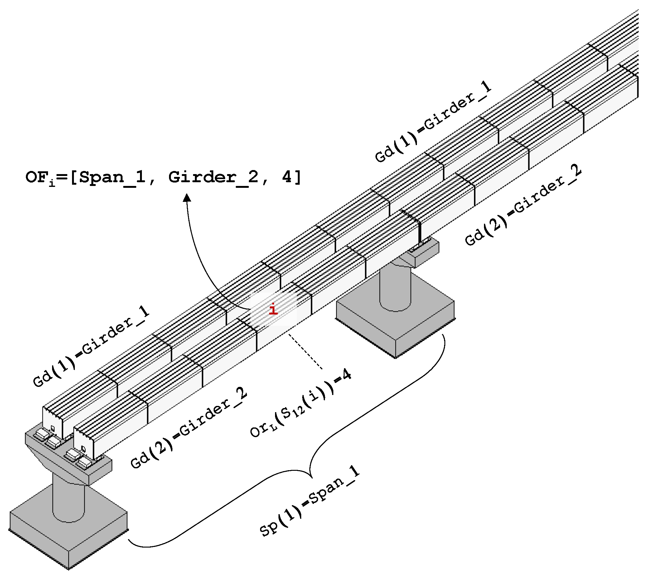
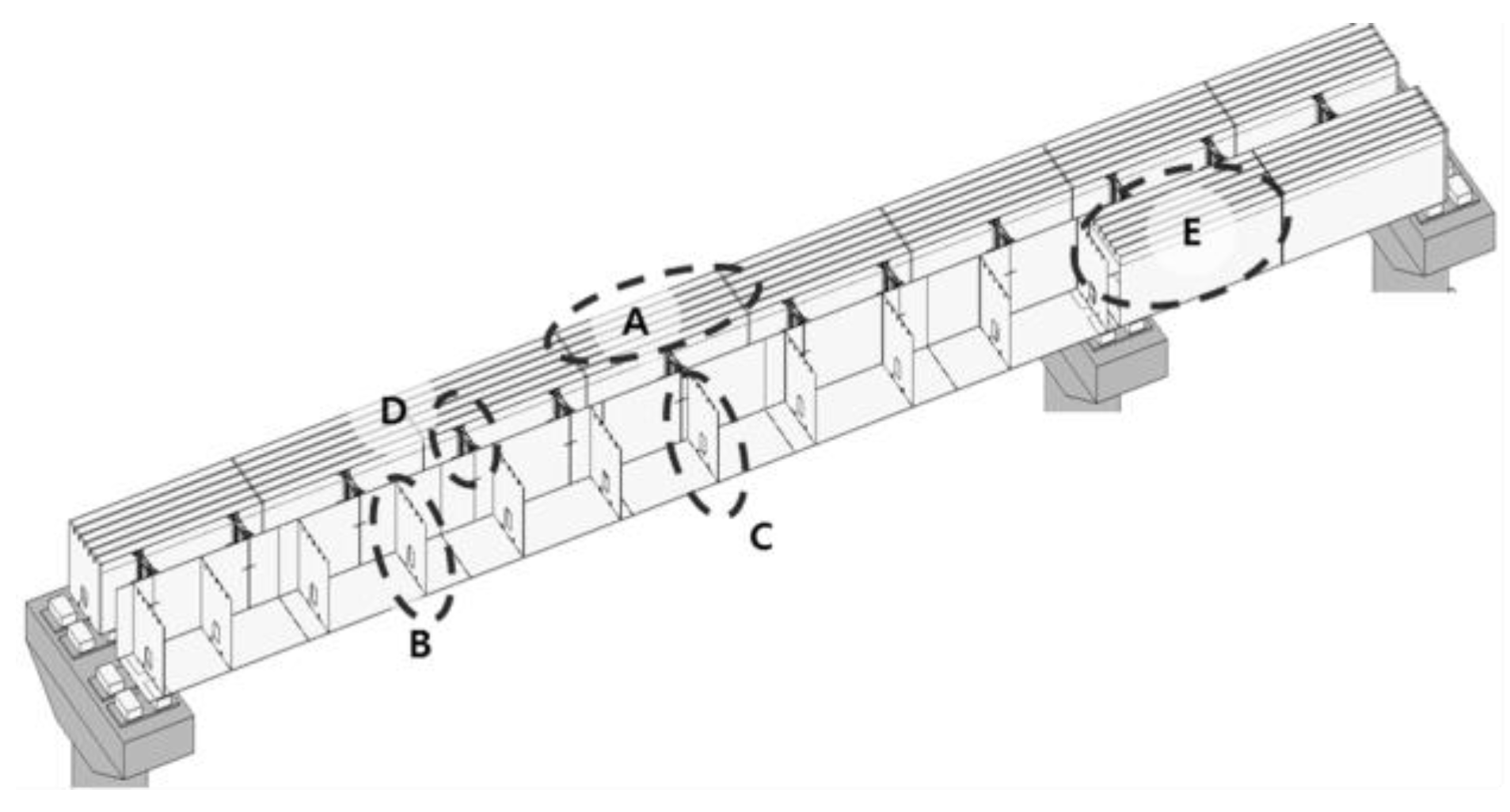
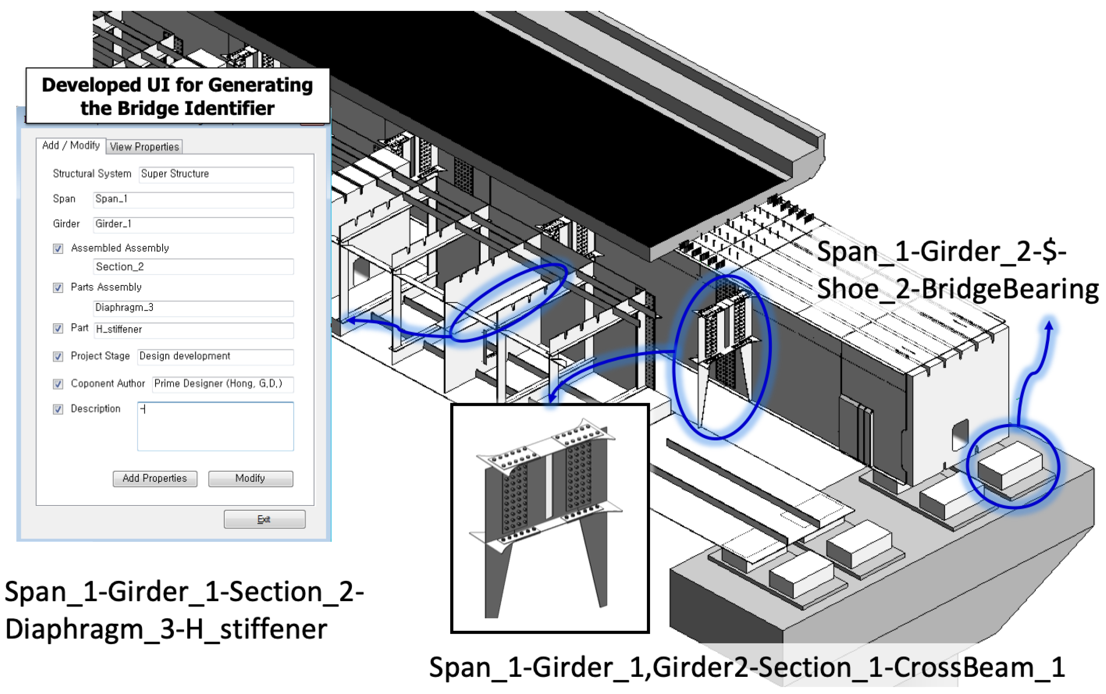
4.2. Automated Naming Algorithm for the Identification of Bridge Components

We investigated the method of automatically generating the identifiers for the bridge components for which the semantic information of function and usage has been generated. In this study, the application of the automated identifier generation method was based on the assumption that the information for Girder and Span properties is already included, with regard to the Assembled Assembly and Parts Assembly in Figure 5. Here, the exclusion of the Structural System, Girder, and Span properties occur because it is likely that the introduction of an automated technique to problems with few elements, such as the classification of a bridge sub/superstructure or abutment/pier, will be inefficient compared with the manual operation. Since the feature-based semantic identification of components in greater detail than Parts Assembly is not within the scope of this study, it was also excluded.
The identification information of the bridge components was generated by forming feature sets, as shown in Equation (1).
O F i = [ S P ( m ) , G d ( n ) ,   O r L ( S m n ( i ) ) ]
where OFi denotes the feature set of object i. Gd(n) refers to the identifier of the nth girder and Sp(m) indicates the identifier of the mth span. OrL(Smn(i)) is the ordinal information of object i arranged along the axis of the bridge in the spanwise direction (Y′-direction). Smn is defined as shown in Equation (2).
S m n ( i ) = { i | S ( S p ( m ) ) S ( G d ( n ) ) }
where S(Sp(m)) and S(Gd(n)) are for the ith object that belongs to Sp(m) and Gd(n). Figure 9 shows an example of OFi.
Objects that are recurrently arranged, such as a section, are identified using the following rule.
Rule: If objects i and j satisfy Equation (3), then it is defined that Smn(i) = Smn(j).
{ | p x ( i ) p x ( j ) ε | } { α j , β i : c ( i ) β = c ( j ) α }
Here, p(i) and p(j) are the centroid (in the local coordinate system) of the objects i and j that are arranged along the axis of the spanwise bridge direction (Y′-direction). ε is the tolerance that processes the exceptional case of modeling, in which an object is divided into two. Its value should be higher than zero, but, when it is smaller, it divides an object more strictly, which may vary depending on the target model. In this study, the authors used ε = 1 mm. c(i)β is the centroid coordinate values of the βth face of object i, and α is the nearer face, while β is the further face, with reference to the axis of the bridge spanwise direction. In other words, the rule is the identification of identical objects from among recurrently arranged objects, in terms of the semantic classification of the bridge.
The applicability of the developed algorithm was verified by the application to the sample bridge model shown in Figure 10. The sample bridge consists of two girder intervals and two span intervals, and the intervals used for the algorithm verification are the section interval (Assembled Assembly) and the diaphragm and crossbeam (Parts Assembly) inside the section.
As mentioned earlier, the Girder and Span properties of each component have already been entered. The elements to be automatically identified were 18 sections, 14 diaphragms, and 12 crossbeams. Algorithms were first applied to the sections, and subsequently to the diaphragms and crossbeams. The results appeared in the form of Span_ID-Girder_ID-AssembledAssembly_ID-PartsAssembly_ID, using the elements of the set proposed in Equation (1). The 44 individual components all contained the identifiers in the correct format, as shown in the following example. During this process, for objects that extend over multiple elements, we adopted the expression of all included elements. This was true in the case of D, where the property Girder_1,Girder_2 was generated as the Girder property.
  • A: Span_1-Girder_1-Section_4
  • B: Span_1-Girder_2-Section_2-Diaphragm_2
  • C: Span_1-Girder_2-Section_4-Diaphragm_1
  • D: Span_1-Girder_1,Girder_2-Section_3-CrossBeam_1
  • E: Span_2-Girder_2-Section_1

5. Discussion

To verify the applicability of the bridge information model containing functional semantic information, we examined whether it can be applied to the basic quantity take-off of an actual bridge and information linkage with the external information, and whether it is possible to regenerate a model through an IPF-based semantic search. In an actual bridge design process, the result of the quantity take-off includes the as-built structure, the temporary facilities, and the components of the discarded part. However, this study aimed to examine whether the retrieval of the functional components can be used for quantity take-off. Therefore, only the as-built bridge model as appearing in the design document was used for the quantity take-off. Since the material quantity in the final product directly relates to the volume of the product, there is no room for problems, as long as the geometric information is correctly processed. However, for a more advanced form of decision-making support, such as the quantity take-off of bridge members with identical functions, or the quantity take-off of a specific member, the model must be able to provide information in various forms. This involves the critical requirement of accurate identification information for the bridge components, which can be said to be redundant geometries that represent the real world. For example, while a crossbeam and the main girder of the bridge can be identically represented as physical objects, these elements clearly have different functions, which require that the quantity take-off is considered separately for these two elements. Therefore, the process of applicability verification of the bridge information model in this study was as follows. (1) The bridge information model was generated using BIM authoring software. (2) The semantic information concerning the necessary bridge components was generated by the user, using Figure 8 or Algorithm 1. (3) Identifiers of the members were generated using the automated naming method. (4) The model applicability based on the bridge components and identifiers was examined. (5) Using the generated IPF, the semantics-based model regeneration of bridge components was examined.

5.1. IFC-Based Model Implementation of a Steel Box Girder Bridge Structure

To examine the applicability, some parts of the real steel box girder bridge were modeled using developed IFC and user-defined PSETs in this study. Figure 11 shows the standard cross section and current endpoint of the steel box interval of the target bridge that was modeled. The actual bridge consists of a total of 34 spans, and has a length of 1441 m. In this study, two span intervals were examined, with each span being 50 m. Figure 12 shows the result of the detailed design-level modeling based on the design drawings. As shown in the figure, each bridge component contains a corresponding identifier. Basically, the process of generating such information entails repetitive manual operations. In this study, we could reduce the information-generating time through multi-selection of objects as well as the use of applied object libraries (in the case of Autodesk-Revit families) that include the basic and shared data. Figure 13 is the IFC-based bridge information model generated through the integration of geometric model and semantic identifiers in accordance with a process of Figure 7. The model objects and properties have been checked via Solibri Model Checker. Additional information on identification could be found on the info tab with the name of the PSET.

5.2. Quantity Take-Off Check Using the Bridge Data Model

The basic quantity take-off was derived using the steel box girder bridge information model, and the result was compared to the design drawings for that bridge. Table 4a shows part of quantities specified in the design drawings, while Table 4b shows the quantities corresponding to the components in Table 4a, calculated using the information model. Functions provided by Revit were used for the quantity take-off based on the information model.
In terms of the quantities of each component, the results were identical. However, the quantity take-off results were provided in a faster and more detailed manner, as compared with the previous method of using the design drawings. The specific name of each component, as well as the corresponding quantity and quantity, can be provided in a specific form. For example, compared to “Horizontal stiffener” in Table 4a, “Horizontal stiffener” in Table 4b is separated into two elements. Nevertheless, while comparing the results, it was noted that the representation of components differed between the users, requiring additional manual tasks for adequately identifying the components.

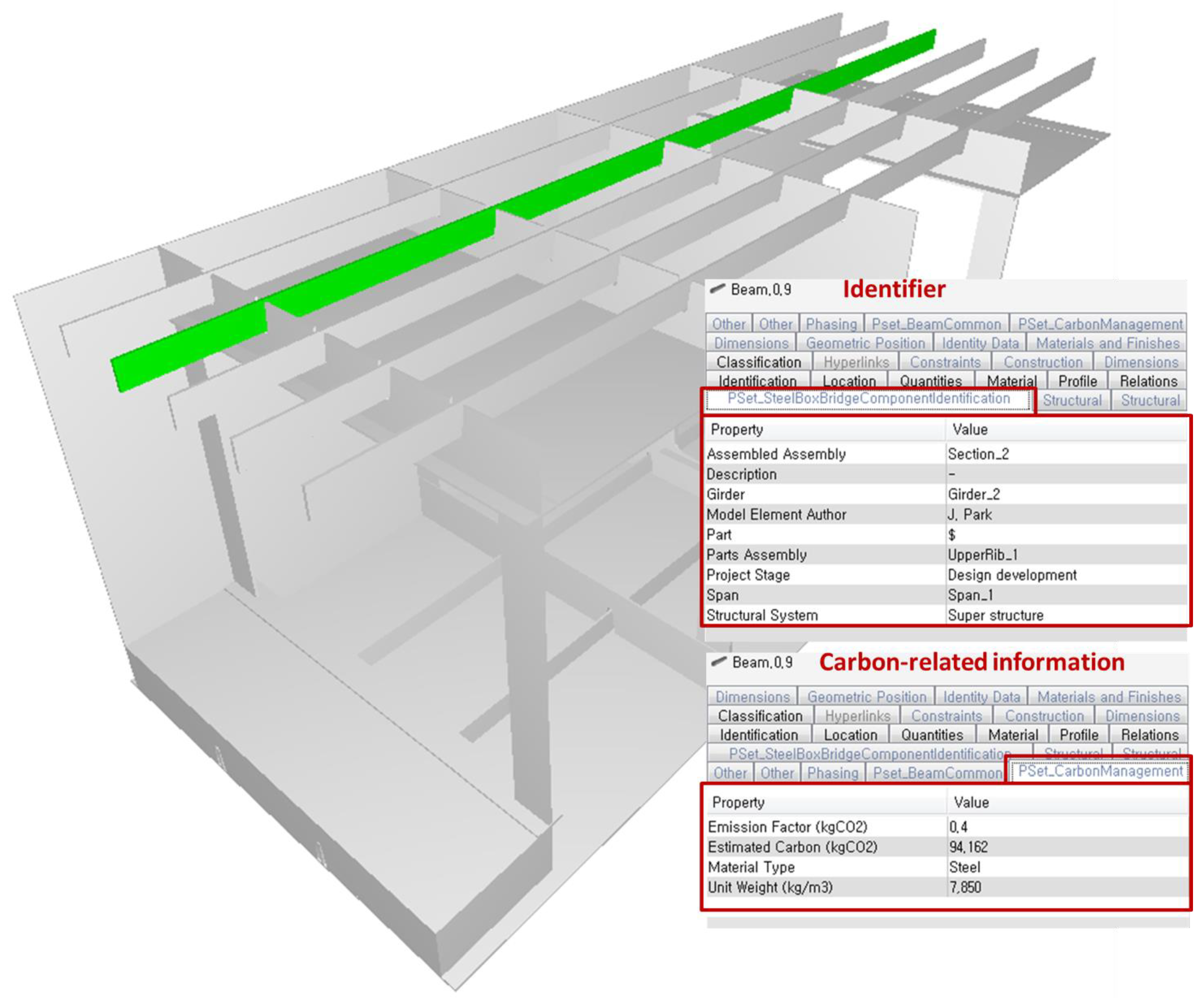
5.3. Estimation of Carbon Emission Using IFC-Based Bridge Information Model

The United Nations Framework Convention on Climate Change (UNFCCC) has suggested that all nations should attempt to reduce greenhouse gas emissions. A large amount of carbon is emitted from civil engineering structures. However, the amount of carbon emitted has not been calculated perfectly because structural stability has received more emphasis and detailed assessment processes for such calculations do not exist at this time. Carbon emissions are calculated by employing a method that estimates an emissions source unit based on the embodied energy generated during the production of the material that is used over the whole life cycle of the facility. However, the proposed guidelines are based on material or equipment units according to the work process rather than the component unit of a facility. Therefore, from the viewpoint of the product, directly examining the effect of carbon emissions via components is disadvantageous. This study did not aim to accurately calculate the carbon emissions generated from bridge structures; rather, it attempted to verify whether the carbon emissions calculated for the structure and stored in the BIM data can be meaningfully reused. This study considered the following elements for carbon emissions calculations:
  • Quantity: Utilization of the volume from the viewpoint of the product, based on the design phase.
  • Identification: Utilization of the IFC and the IFC user-defined PSET proposed in previous sections.
Carbon emissions were estimated using a calculation method, in which each component in the structure is multiplied by a carbon emissions factor, as shown in Equation (4), by referring to “the carbon emissions calculation according to material input”, as proposed by Ministry of Land, Infrastructure and Transport of Korea [48].
E S T i = O I i × E F c o 2
where i is an object identifier of object information OI equivalent to the total number of objects in the structure. In other words, the carbon emissions estimation was conducted for each individual component of the structure. A method of summing the emissions of individual components was used to calculate the total carbon emissions. EFCO2 is the carbon emissions factor. In this case, a carbon emissions factor of 430.87 kgCO 2 / m 3 (ready-mixed concrete No. 25-240-15) was used for concrete material. A unit weight of 7850 kg / m 3 and a carbon emissions factor of 0.4 kgCO 2 / kg were used for steel materials. The unit weight of asphalt concrete was 2340 kg / m 3 and its carbon emissions factor was 0.01 kgCO 2 / kg .
The emissions factor and estimated carbon quantity of the component were saved so that the calculated result can be reused for other applications. This study additionally defined an IFC user-defined PSET to save the obtained information, as listed in Table 5. Table 3 is used to present the semantic information of components.
The results were checked by applying the carbon emissions calculation process to the bridge information model. Table 6 shows a part of the carbon emissions for one span in a superstructure of the bridge model, and Figure 14 shows the IFC-based information model including carbon emissions-related information using PSET.
The estimated carbon emissions were calculated as 1068.65 tCO2 for the bridge information model. It is difficult to say that the results have engineering implications. However, the results can be quickly reviewed for each of the detailed components. BIM model is advantageous for the management of new knowledge, such as carbon emissions, which is induced by digital models and external factors. In other words, BIM is effective at utilizing an external DB depending on the situation. In this study, however, the additional information was stored in the independent building information model to confirm that it is possible to extract or search for the needed result according to the specific component or detailed condition. Therefore, the estimation process has been simplified. It is worthwhile referring to the study of See et al. [49] when applying BIM’s Information Delivery Manual (IDM) process, or the study of Choi et al. [50], which reflects LoD, to estimate the detailed quantity take-off or carbon emissions using BIM.

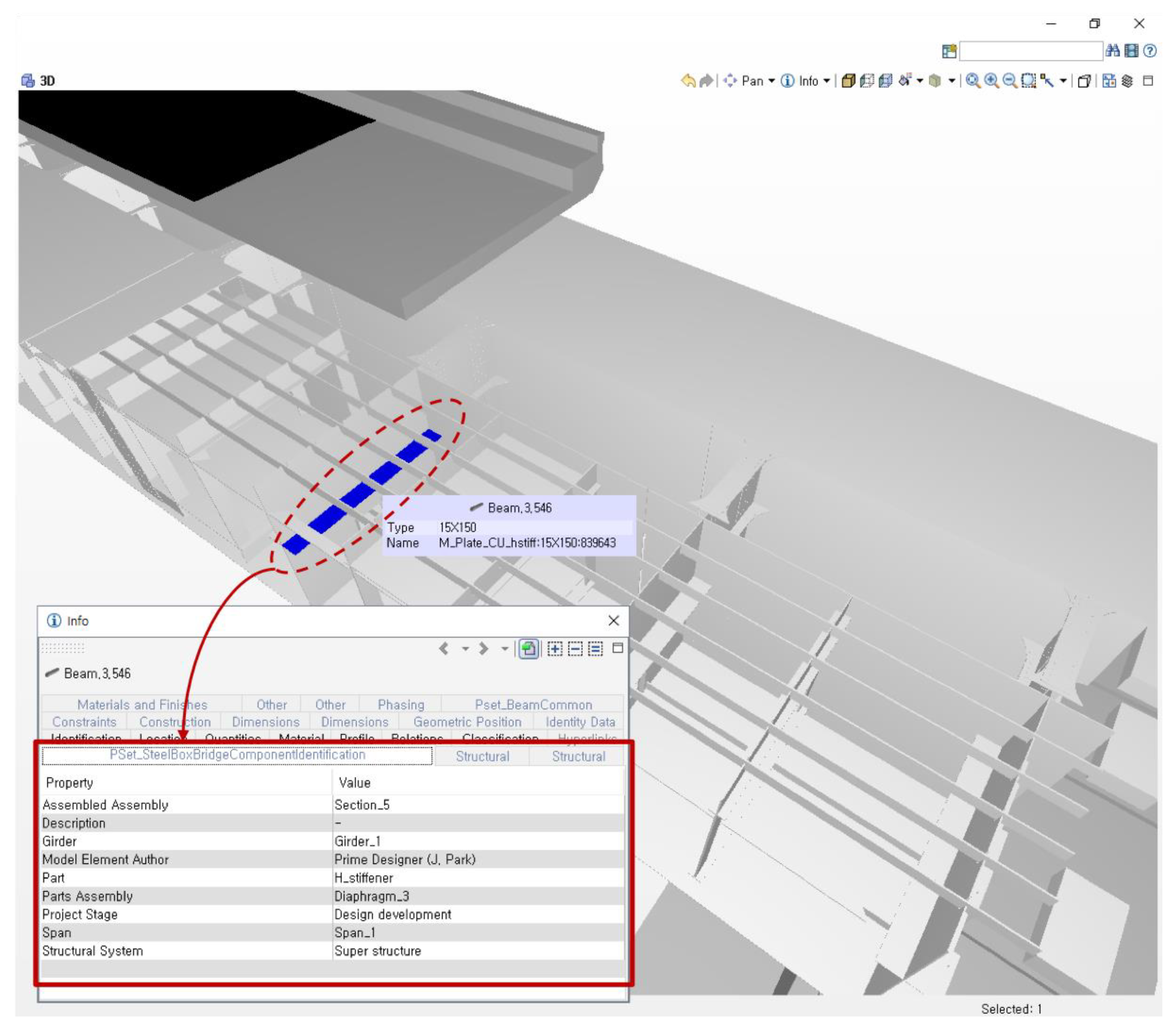
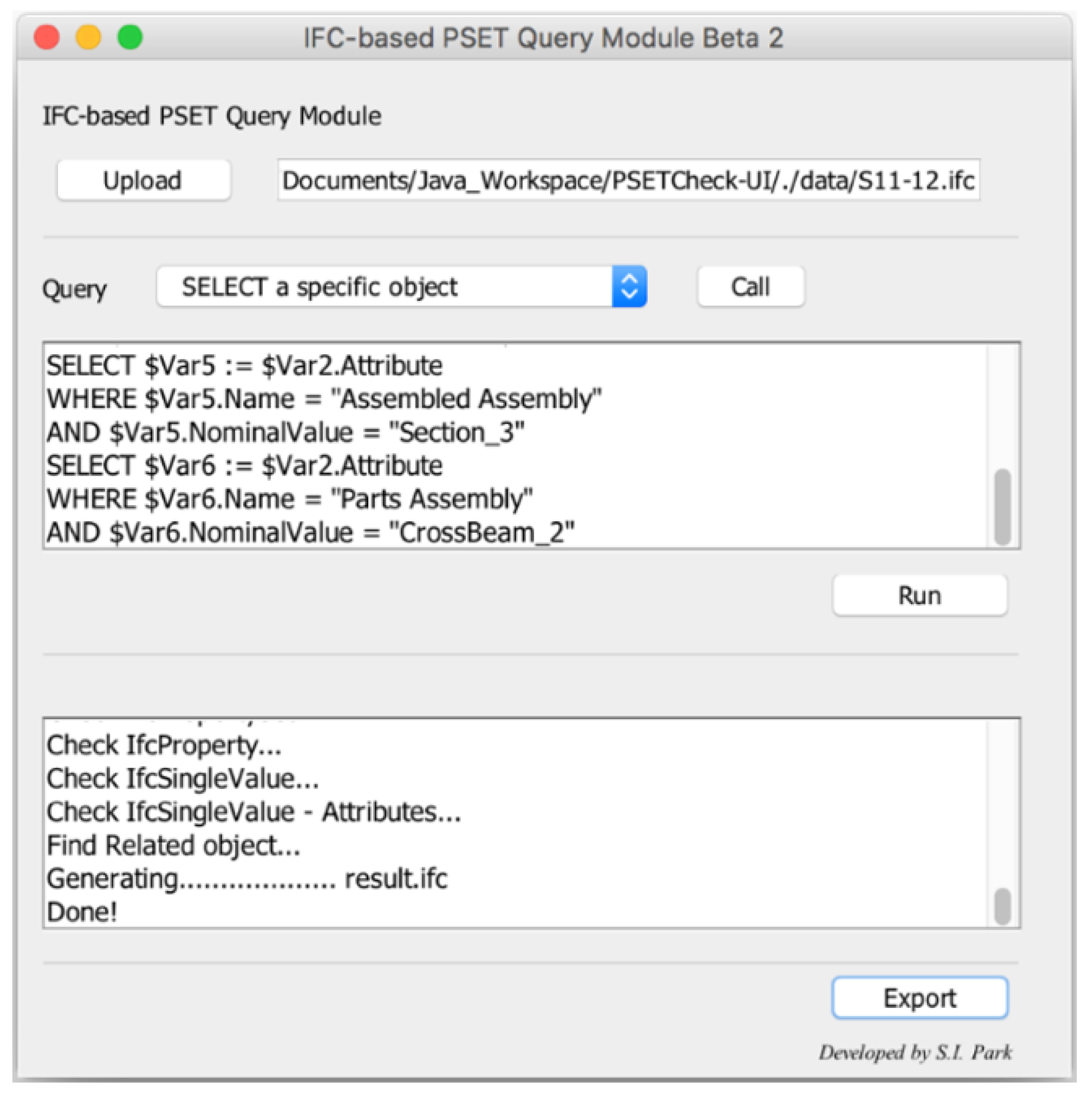
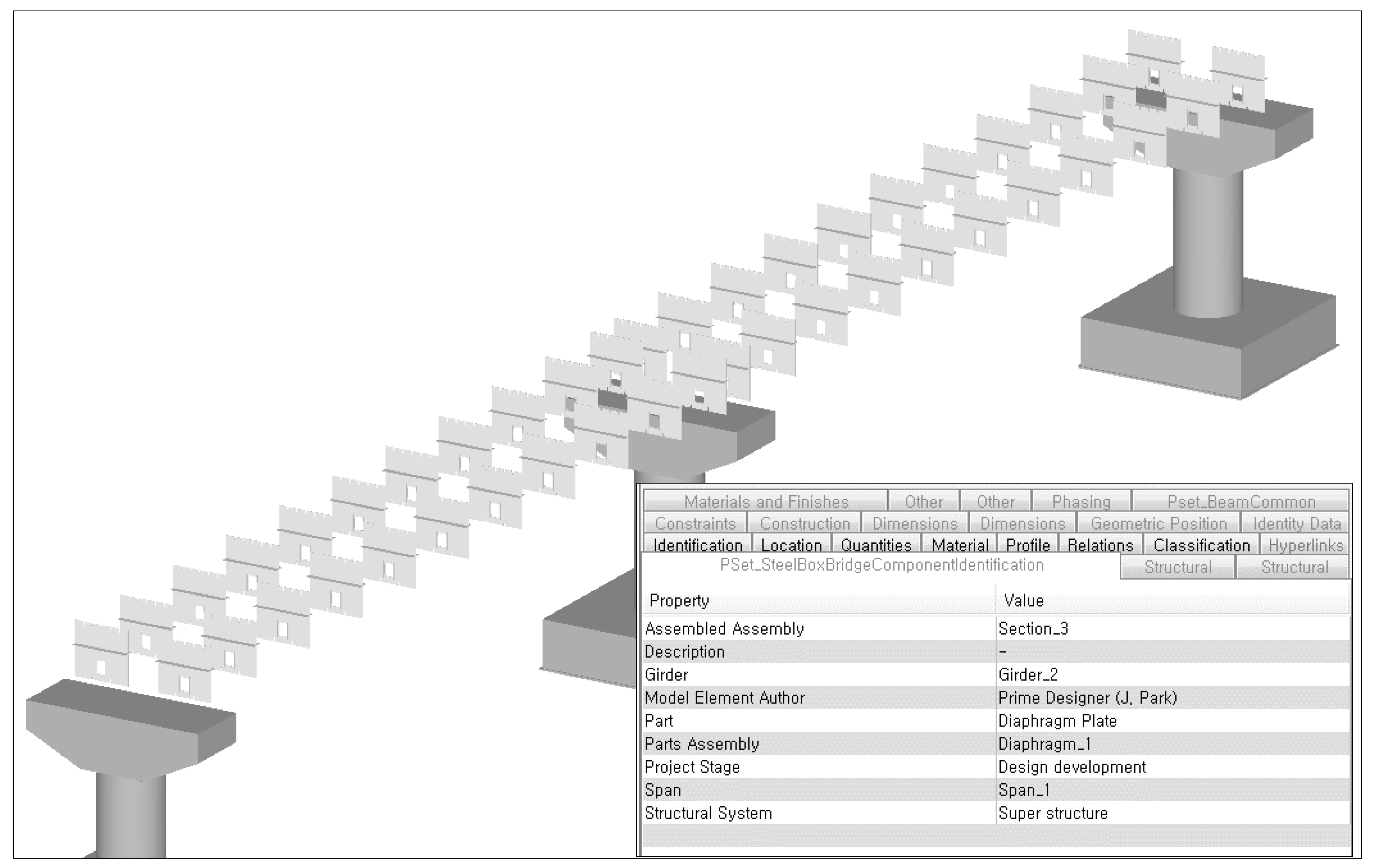
5.4. Extraction Test Based on Semantic Meaning of Steel Bridge Components

The IFC-based bridge information model proposed in this study has computer-understandable identification information within the model itself. Consequently, in this study, it was examined whether each object corresponding to the identification information of the components was extracted, using the generated IPF.
Mazairac and Beetz [51] proposed the Building Information Model Query Language (BimQL) to enable the extraction of certain values from a model in an IPFF format. However, this is currently at the research level, and supports the extraction of certain information only, with the combination of query results not being supported. Therefore, in this study, we developed an information extraction module based on the property value query from the IFC PSET, with reference to the grammar of the BimQL. The module developed in this study addresses the property values of the IfcPropertySet only, as the development of generalized BIM query terms was considered beyond the scope of this study. Algorithm 2 shows the underlying code for regenerating queried objects or retrieving the results based on PSET data. Input data are query sentence and the “Population” is the same as that of Algorithm 1. The query sentence was separated into the required words by string support Java library. The entry IFC entity is IfcPropertySet stored in the “Population” (Lines 1–3), and the search scope was reduced by comparison between the name of IfcPropertySet and the name of the input PSET (Lines 4 and 5). The objects to be extracted can be specified by comparing the attributes of the IfcProperty included in the IfcPropertySet and the identifier of the bridge component (Line 6–12). One of the subtypes of the IfcObjectDefinition connected with IfcPropertySet can be derived through a findRelatedObjects function (Line 13). Figure 15 shows the UI module developed according to Algorithm 2.
Algorithm 2. Algorithm for responding results according to the query sentence.
Input 1: qs - Query sentence
Input 2: Population of generated IFC file - schemaParser.Population typeOutput: Responses according to the qeury
1  EntityInstanceSet: set of EntityInstance of IfcPropertySet
2  while (EntityInstanceSet.hasNext())
3  Ifcpropertyset in Figure 2: IfcPropertySet class included in the Population
4  if (Ifcpropertyset.getName() == qs.EntityType)
5    SetIfcproperty: set of IfcProperty in Figure 2
6    checking (HasProperties) in Figure 2
7    while (SetIfcproperty.hasNext())
8      Ifcproperty in Figure 2: IfcProperty class included in the Population
9      queriedName = Ifcproperty.getName()
10      queriedValue = Ifcproperty.getNominalvalue()
11      checking (queriedName == qs.Var.Name)
12      checking (queriedValue == qs.Var.NominalValue)
13    findRelatedObjects(Ifcpropertyset)

Function findRelatedObjects(Ifcpropertyset)
14 EntityInstanceSet relatingPropertyDefinition = Ifcpropertyset.usedin(Ifcreldefinesbyproperties.relatingpropertydefinition_ATT);
15 while (relatingPropertyDefinition.hasNext())
16 Ifcreldefinesbyproperties in Figure 2: IfcRelDefinesByProperties class included in the Population
17 SetIfcobjectdefinition = ifcRelDefinesProperties.getRelatedobjects()
18 while (SetIfcobjectdefinition.hasNext())
19    Domain of relatedObject = Ifcobjectdefinition.getLocalDomain()
20    getting geometric information using relatedObject class
The query format was fundamentally based on the items defined in Table 3, and the instances generated during the bridge information modeling. Query Sentence (1) shows the extraction of all objects(*) that include the identifier, “Diaphragm” from the target bridge model, of which the result is shown in Figure 16. In Query Sentence (1), Var1.ALL represents the calling of all entities that are connected to Var1. Moreover, the pier models in Figure 16 were deliberately added to determine the location of each diaphragm, and are irrelevant to Query Sentence (1). Figure 16 shows 44 diaphragms, which appear to be identical to those shown in Figure 11.
Query Sentence (1):
  • SELECT $Var1.ALL WHERE $Var1.EntityType = IfcPropertySet AND $Var1.Name = “Pset_SteelBoxBridgeComponentIdentification
  • SELECT $Var2 := $Var1.Attribute.HasProperties
  • SELECT $Var3 := $Var2.Attribute WHERE $Var3.Name = “Parts Assembly” AND $Var3.NominalValue = “Diaphragm*
It was examined whether relevant objects can be extracted based on a specified instance only, regardless of the upper- and lower-levels of a specific element. Query Sentence (2) is a request for the extraction of objects containing the identifier, “Section_2” from the instances of Assembled Assembly. This is possible since only “Assembled Assembly” is selected as the object extraction criterion. Figure 17a shows the corresponding result. Four Section objects were extracted, with each object containing sub-level elements of Parts Assembly and Part.
Query Sentence (2):
  • SELECT $Var1.ALL WHERE $Var1.EntityType = IfcPropertySet AND $Var1.Name = “Pset_SteelBoxBridgeComponentIdentification
  • SELECT $Var2 := $Var1.Attribute.HasProperties
  • SELECT $Var3 := $Var2.Attribute WHERE $Var3.Name = “Assembled Assembly” AND $Var3.NominalValue = “Section_2”
Accurate extraction of a single element was possible through the addition of a conditional statement for the extraction of the element. Query Sentence (3) is the request for the extraction of the object with the identifier Span_1-Girder_1,Girder_2-Section_3-CrossBeam_2; the result is shown in Figure 17b.
Query Sentence (3):
  • SELECT $Var1.ALL WHERE $Var1.EntityType = IfcPropertySet AND $Var1.Name = “Pset_SteelBoxBridgeComponentIdentification
  • SELECT $Var2 := $Var1.Attribute.HasProperties
  • 40) SELECT $Var3 := $Var2.Attribute WHERE $Var3.Name = “Span” AND $Var3.NominalValue = “Span_1”
  • SELECT $Var4 := $Var2.Attribute WHERE $Var4.Name = “Girder” AND $Var4.NominalValue = “Girder_1,Girder_2”
  • SELECT $Var5 := $Var2.Attribute WHERE $Var5.Name = “Assembled Assembly” AND $Var5.NominalValue = “Section_3”
  • SELECT $Var6 := $Var2.Attribute WHERE $Var6.Name = “Parts Assembly” AND $Var6.NominalValue = “CrossBeam_2”
Additional information, such as carbon emissions associated with the object, was reviewed. Query Sentence (4) retrieves the carbon emissions stored in the IPF by utilizing an identifier in the bridge component.
Query Sentence (4):
  • SELECT $Var1 WHERE $Var1.EntityType = IfcPropertySet AND $Var1.Name = “Pset_SteelBoxBridgeComponentIdentification
  • SELECT $Var2 := $Var1.Attribute.HasProperties
  • SELECT $Var3 := $Var2.Attribute WHERE $Var3.Name = “Span” AND $Var3.NominalValue = “Span_1
  • SELECT $Var4 := $Var2.Attribute WHERE $Var4.Name = “Girder” AND $Var4.NominalValue = “Girder_1
  • SELECT $Var5 := $Var2.Attribute WHERE $Var5.Name = “Assembled Assembly” AND $Var5.NominalValue = “Section_5
  • SELECT $Var6 := $Var2.Attribute WHERE $Var6.Name = “Parts Assembly” AND $Var6.NominalValue = “Diaphragm_1
  • SELECT $Var7 WHERE $Var7.EntityType = IfcPropertySet AND $Var7.Name = “Pset_CarbonManagement
  • SELECT $Var8 := $Var7.Attribute.HasProperties
  • SELECT $Var9 := $Var8.Attribute WHERE $Var9.Name = “Estimated Carbon
  • SELECT $Var10 WHERE $Var9.NominalValue;
The difference between Query Sentence (4) and Query Sentences (1)–(3) is that the former only retrieve information on the corresponding object because the “ALL” keyword is not used. Accordingly, the query response is 410.56, which is a result that verifies that the information of the corresponding object can be utilized according to the user’s needs. Table 7 shows the results derived using such a method.
These results imply that it is possible to semantically extract the model data or regenerate the information model depending on the user’s need using the bridge information model, which contains identification information in a clear manner.

6. Conclusions

Currently, IFC has been firmly established as the standard data schema for BIM. Most BIM authoring software packages support the input and output of IFC format, and, as a result, BIM models generated in IFC format can be utilized with various application software. However, the current IFC addresses building structures only, and hence cannot be used for bridge structures, except for its geometrical information.
We propose a method that overcomes the limitation that the information modeling of a steel box girder bridge based on IFC cannot support the generation of semantic information for the components of bridge structures. For this purpose, the components of a steel box girder bridge were classified into those used during the fundamental planning, fundamental design, and detailed design phases, and the items necessary for the generation of semantic information were selected based on this classification. The items necessary for the generation of functional semantic information were largely classified into spatial and physical aspects, to allow the simultaneous consideration of both the meaning from the location of the component, and the functional meaning from the properties of the component. To include the semantic information in the IFC-based steel bridge information model, we propose a method of identifying the constituent elements of the information model. Using the method described, it could be reflected in the IFC model through the user-defined PSETs of the framework of IFC. In addition, to verify the architectural validity of the IFC with the generated semantic identification information of the bridge components, an actual IPF was generated, and its internal data were examined. In this process, it was troublesome to generate the unique identifier through repetitive manual operation in the case of a component (e.g., a cross beam) including small elements and a plurality of elements. However, we could improve the speed using the object library with the unique identifier and applying the automated naming algorithm for the identification of bridge components. The generated bridge information model was used to confirm the functional semantic meanings of individual components, and it was checked whether additional external information such as carbon emissions could be linked for specific bridge components. It was observed that a semantic search for each bridge component is possible by generating a bridge information model in an IPF format. Through this process, we reviewed and discussed the applicability of bridge information model. The usefulness of the generated identification information of the bridge components was high. It was effective to obtain the information on the detailed components in cases of quantity take-off and carbon emissions estimation as well as object extraction and information retrieval by applying query language to the IPF.
While BIM based on an IFC data model is central to the interoperability of information, it is still insufficient for implementing true BIM models owing to the absence of support of IFC for bridge structures. Ultimately, a data model that supports bridge structures, or even all civil structures, must be developed, and relevant works are in progress. However, an appreciable amount of time is required for end-users to utilize the data models, since they must be continuously updated. Thus, specialized software that supports the updated model must be subsequently developed for its application. The information modeling of the steel bridge using IFC and user-defined PSETs proposed herein enables additional external data to be applied in the information model while maintaining the current IFC frame. It helps to reduce the constraints on the creation of an accompanied functional meaning when IFC-based information modeling is carried out on facilities such as civil infrastructures other than buildings in the current BIM environment. Moreover, the method for automated identification of components can be applied regardless of the data model type, which is thought to be a highly useful feature, considering that this can be applied to civil structures other than steel box girder bridges in the future.

Author Contributions

S.I.P. conceived, designed, and programmed the algorithm, as well as analyzed the results. J.P. contributed to generating the information models and the experiment the new algorithms and verified the data quality. B.-G.K. programmed the algorithm and verified the data quality. S.-H.L. supervised the entire research.

Funding

This research was supported by a grant (18RTRP-B104237-04) from Railroad Technology Research Program funded by Ministry of Land, Infrastructure and Transport (MOLIT) of Korean government.

Conflicts of Interest

The authors declare no conflict of interest.

References

  1. Eadie, R.; Browne, M.; Odeyinka, H.; McKeown, C.; McNiff, S. BIM implementation throughout the UK construction project lifecycle: An analysis. Autom. Constr. 2013, 36, 145–151. [Google Scholar] [CrossRef]
  2. Borrmann, A.; Kolbe, T.H.; Donaubauer, A.; Steuer, H.; Jubierre, J.R.; Flurl, M. Multi-scale geometric-semantic modeling of shield tunnels for GIS and BIM applications. Comput.-Aided Civ. Infrastruct. Eng. 2015, 30, 263–281. [Google Scholar] [CrossRef]
  3. Yau, N.J.; Tsai, M.K.; Yulita, E.N. Improving efficiency for post-disaster transitional housing in Indonesia: An exploratory case study. Disaster Prev. Manag. 2014, 23, 157–174. [Google Scholar] [CrossRef]
  4. Irizarry, J.; Karan, E.P. Optimizing location of tower cranes on construction sites through GIS and BIM integration. ITcon 2012, 17, 351–366. [Google Scholar]
  5. Liu, X.; Wang, X.; Wright, G.; Cheng, J.; Li, X.; Liu, R. A State-of-the-art review on the integration of Building Information Modeling (BIM) and Geographic Information System (GIS). ISPRS Int. J. Geo-Inf. 2017, 6, 53. [Google Scholar] [CrossRef]
  6. Kim, K.R.; Kim, H.; Kim, W.; Kim, C.; Kim, J.; Yu, J. Integration of ifc objects and facility management work information using Semantic Web. Autom. Constr. 2018, 87, 173–187. [Google Scholar] [CrossRef]
  7. Pishdad-Bozorgi, P.; Gao, X.; Eastman, C.; Self, A.P. Planning and developing facility management-enabled building information model (FM-enabled BIM). Autom. Constr. 2018, 87, 22–38. [Google Scholar] [CrossRef]
  8. Mangal, M.; Cheng, J.C.P. Automated optimization of steel reinforcement in RC building frames using building information modeling and hybrid genetic algorithm. Autom. Constr. 2018, 90, 39–57. [Google Scholar] [CrossRef]
  9. Ramaji, I.J.; Memari, A.M. Interpretation of structural analytical models from the coordination view in building information models. Autom. Constr. 2018, 90, 117–133. [Google Scholar] [CrossRef]
  10. Ninić, J.; Koch, C.; Stascheit, J. An integrated platform for design and numerical analysis of shield tunnelling processes on different levels of detail. Adv. Eng. Softw. 2017, 112, 165–179. [Google Scholar] [CrossRef] [Green Version]
  11. ISO-TC184/SC4. ISO 16739:2013 Industry Foundation Classes (IFC) for Data Sharing in the Construction and Facility Management Industries. ISO, 2013. [Google Scholar]
  12. Hira, S. Bay Bridge Construction. Available online: http://beyonddesign.typepad.com/posts/2013/09/bay-bridge-construction.html (accessed on 1 November 2018).
  13. Choi, N.-J.; Kim, M.-C.; Kim, J.-G.; Kook, C.-G. Barriers and priorities analysis in case of introducing civil BIM into public organizations. Mag. Korean Soc. Civ. Eng. 2015, 63, 52–60. [Google Scholar]
  14. Moore, G.A. Crossing the Chasm, 1st ed.; Harper Business Essentials: New York, NY, USA, 1991. [Google Scholar]
  15. Rogers, E.M. Diffusion of Innovations, 1st ed.; Free Press: New York, NY, USA, 1962. [Google Scholar]
  16. Gartner Hype Cycle. Available online: http://www.gartner.com/technology/research/methodologies/hype-cycle.jsp (accessed on 1 November 2018).
  17. Naney, D.; Goser, C.; Azambuja, M. Accelerating the adoption of lean thinking in the construction industry. In Proceedings of the 20th Annual Conference of the International Group for Lean Construction, San Diego, CA, USA, 18–20 July 2012. [Google Scholar]
  18. Björk, B.-C.; Penttila, H. A scenario for the development and implementation of a building product model standard. Adv. Eng. Softw. Workstn. 1989, 11, 176–187. [Google Scholar] [CrossRef]
  19. Cerovsek, T. A review and outlook for a “Building Information Model” (BIM): A multi-standpoint framework for technological development. Adv. Eng. Inform. 2011, 25, 224–244. [Google Scholar] [CrossRef]
  20. Lee, S.-H.; Kim, B.-G. IFC extension for road structures and digital modeling. Procedia Eng. 2011, 14, 1037–1042. [Google Scholar] [CrossRef]
  21. ISO-TC184/SC4. ISO 10303-11: 2004 Industrial Automation Systems and Integration—Product Data Representation and Exchange—Part 11: Description Methods: The EXPRESS Language Reference Manual. ISO, 2004. [Google Scholar]
  22. W3C Extensible Markup Language (XML). Available online: http://www.w3.org/XML/ (accessed on 1 November 2018).
  23. Gielingh, W. General AEC Reference Model (GARM): An aid for the integration of application specific product definition models. In Proceedings of the CIB Seminar Conceptual Modeling of Buildings, Lund, Sweden, 25–27 October 1988; pp. 165–178. [Google Scholar]
  24. Aoyama, N. Development and application of STEP for bridges maintenance. In Proceedings of the 23rd symposium on Civil Engineering Information Processing System, Tokyo, Japan, 27–28 October 1998; pp. 149–152. [Google Scholar]
  25. Mikami, I.; Tanaka, S.; Kubota, S.; Ishii, Y. Construction of database for highway bridges’ product data models using internet technology. J. Struct. Eng. JSCE 1999, 45, 511–522. [Google Scholar]
  26. Halfawy, M.R.; Hadipriono, F.C.; Duane, J.; Larew, R. Development of model-based systems for integrated design of highway bridges. In Proceedings of the International Conference on Civil, Structural and Environmental Engineering Computing, Rome, Italy, 30 August–2 September 2005. Paper 30. [Google Scholar] [CrossRef]
  27. Crowley, A.J.; Watson, A.S. CIMsteel Integration Standards Release 2: Overview; Steel Construction Institute: Berkshire, UK, 2000. [Google Scholar]
  28. Lee, S.-H.; Jeong, Y.-S. A system integration framework through development of ISO 10303-based product model for steel bridges. Autom. Constr. 2006, 15, 212–228. [Google Scholar] [CrossRef]
  29. Eastman, C.M.; Teicholz, P.; Sacks, R.; Liston, K. BIM Handbook: A Guide to Building Information Modeling for Owners, Managers, Designers, Engineers, and Contractors; John Wiley and Sons: Hoboken, NJ, USA, 2008. [Google Scholar]
  30. Arthaud, G.; Lebegue, E. IFC-Bridge V2 Data Model Edition R7; IAI French Chapter. 2007.
  31. Yabuki, N.; Lebegue, E.; Gual, J.; Shitani, T. International collaboration for developing the bridge product model “IFC-BRIDGE”. In Proceedings of the Joint International Conference on Computing and Decision Making in Civil and Building Engineering, Montreal, QC, Canada, 14–16 June 2006; pp. 1927–1936. [Google Scholar]
  32. Lee, S.-H.; Park, S.I.; Park, J. BIM and Its Application to Civil Engineering: How to Overcome the Limitations of Current BIM Technologies. In Proceedings of the 6th Civil Engineering Conference in Asia Region (CECAR6), Jakarta, Indonesia, 20–22 August 2013. [Google Scholar]
  33. Liebich, T. IFC for INFRAstructure. In Proceedings of the INFRA-BIM Workshop, Helsinki, Finland, 19 November 2013. [Google Scholar]
  34. buildingSMART International IFC Alignment. Available online: http://www.buildingsmart-tech.org/infrastructure/projects/alignment (accessed on 2 August 2018).
  35. P6 Project Team IFC Alignment Project–IFC Extension Development Version 1.0. buildingSMART MSG, 2015; 20p.
  36. KICT. IfcRoad Ch.9 Infra IFC Specifications with IfcRoad V0.6. Available online: https://www.buildingsmart.org/standards/standards-tools-services/ (accessed on 1 November 2018).
  37. China Railway BIM Alliance (CRBIM). Railway BIM Data Standard Version 1.0. China Railway BIM Alliance, 2015; 218p. [Google Scholar]
  38. Kolbe, T.H. Representing and exchanging 3D city models with CityGML. In 3D Geo-Information Sciences; Springer: Berlin/Heidelberg, Germany, 2009; pp. 15–31. [Google Scholar]
  39. Gröger, G.; Kolbe, T.H.; Nagel, C.; Häfele, K.-H. OGC City Geography Markup Language (CityGML) Encoding Standard V2.0. Open Geospatial Consortium, 2012. [Google Scholar]
  40. Cambridge Systematics Inc.; Bentley Systems Inc.; Info Tech Inc.; Michael Baker Jr. Inc; Campbell, C.E. XML Schemas for Exchange of Transportation Data–Final Report; Transportation Research Board of the National Academies: Washington, DC, USA, 2006. [Google Scholar]
  41. Ma, Z.; Wei, Z.; Song, W.; Lou, Z. Application and extension of the IFC standard in construction cost estimating for tendering in China. Autom. Constr. 2011, 20, 196–204. [Google Scholar] [CrossRef]
  42. Wix, J. User Defined Property Sets; The Offices of the Engineer Research and Development Center, Construction Engineering Research Laboratory: Champaign, IL, USA, 2009. [Google Scholar]
  43. Ministry of Land, Transport and Maritime Affairs of Korea. Construction Information Classification System of Korea, 2012 ed.; MLTMA: Seoul, Korea, 2012; 59p. (In Korean)
  44. KSSC. Detailed Design Guide for Steel Bridge; Ministry of Construction and Transportation: Seoul, Korea, 2006. (In Korean)
  45. Oh, J.T. Plan and Design of Bridge; Bansuk Tech: Seoul, Korea, 2003. (In Korean) [Google Scholar]
  46. Kim, B.-G.; Lee, S.-H. Enhancement of spatial and physical elements for IFC-based bridge data model. In Proceedings of the 28th International Symposium on Automation and Robotics in Construction (ISARC 2011), Seoul, Korea, 29 June–2 July 2011; pp. 375–376. [Google Scholar] [CrossRef]
  47. ISO-TC59/SC2. ISO 6707-1:2014 Buildings and Civil Engineering Works—Vocabulary—Part 1: General Terms, ISO: Geneva, Switzerland, 2014.
  48. Ministry of Land, Infrastructure and Transport of Korea. IPCC Guideline of Korea; MLIT: Sejong, Korea, 2011. (In Korean)
  49. See, R.; Liebich, T.; Hietanen, J. Design to QTO/Cost Estimating. 2009. Available online: http://www.blis-project.org/IAI-MVD/reporting/listMVDs_4.php?SRT=Name&MVD=GSA-004&DV=2 (accessed on 1 November 2018).
  50. Choi, J.; Choi, J.; Kim, H.; Kim, I. Open BIM-based quantity take-off system for schematic estimation of building frame in early design stage. J. Comput. Des. Eng. 2015, 2, 16–25. [Google Scholar] [CrossRef]
  51. Mazairac, W.; Beetz, J. BIMQL—An open query language for building information models. Adv. Eng. Inform. 2013, 27, 444–456. [Google Scholar] [CrossRef]
Figure 1. Industry foundation classes (IFC) and sets of properties.
Applsci 08 02531 g001
Figure 2. Object, property, and relationship in IFC architecture focused on IfcPropertySet.
Applsci 08 02531 g002
Figure 3. Definition of a coordinate system used in this study.
Applsci 08 02531 g003
Figure 4. Spatial representation of bridge components.
Applsci 08 02531 g004
Figure 5. Physical representation of bridge components.
Applsci 08 02531 g005
Figure 6. Information reassigning concept for the bridge information modeling.
Applsci 08 02531 g006
Figure 7. Basic framework for IFC-based bridge information modeling process.
Applsci 08 02531 g007
Figure 8. Developed user-interface for generating and managing the semantic information of a bridge component.
Applsci 08 02531 g008
Figure 9. Examples of object feature set for a bridge model.
Applsci 08 02531 g009
Figure 10. Sample bridge model for examining the automatic naming algorithm.
Applsci 08 02531 g010
Figure 11. Drawings of a sample steel box girder bridge.
Applsci 08 02531 g011aApplsci 08 02531 g011b
Figure 12. The result of the detailed design-level bridge information model.
Applsci 08 02531 g012
Figure 13. Steel box girder bridge information model based on the IFC with Pset_SteelBoxBridgeComponentsIdentification.
Applsci 08 02531 g013
Figure 14. IFC-based information model including carbon-related information.
Applsci 08 02531 g014
Figure 15. User-interface for semantic information management of bridge data model.
Applsci 08 02531 g015
Figure 16. Query result for extracting all the diaphragms from the bridge model (the pier objects were deliberately added for check the locations of the diaphragms).
Applsci 08 02531 g016
Figure 17. Query result for extracting specific objects from the bridge model (the pier objects were deliberately added for check the locations of the responded results): (a) All Section_2 objects; and (b) CrossBeam_2 object.
Applsci 08 02531 g017
Table 1. Bridge data model comparisons mentioned in this study. IFC: Industry foundation classes; PSETs: property sets; BIM: building information modeling.
Bridge Data ModelFeatureLimitations
AP 203-based ModelsInitial bridge data model based on open data schema
-
Logically impossible to identify the spatial structure
-
Non-consideration of the classification system of the bridge structure
IFC-BridgeAdding new entities for the bridge structure based on current IFC resources
-
Insufficient elements for the detailed bridge components
-
Impossible to use the model in BIM authoring software
CityGMLOne of the facilities of the city information model
-
Logically impossible to identify the spatial structure
-
Insufficient elements for the detailed bridge components
-
Few commercial authoring software packages
TransXMLIncluded as a highway bridge structure in the data model for the transportation data exchange
-
Specialized only in the highway bridges
-
Insufficiently detailed elements from a functional aspect
IFC4 (without user-defined PSETs)The standard data schema of BIM
Various BIM authoring software packages
-
Non-consideration of the bridge structures
IFC4 with user-defined PSETs (in this study)
-
An indirect method to represent the bridge structures
IFC5Currently in early planning phase including the infrastructure domains
Table 2. The breakdown of steel box girder bridge in planning and design phases.
Project Phase
Basic Components
(Planning Phase)
Main Components
(Preliminary Design)
Detailed Components
Accurate Geometric Shape
(Detailed Design)
Super structureFloor slab partSlabPavement, Curb, Slab, Expansion joint, Median stripPavement
CurbOutward, Reinforcement
SlabOutward, Reinforcement, Spacer, Chair block, Stud, Shear connector
Expansion jointOutward, Reinforcement, Pin bearing, Anchor bolt, Steel plate, Rubber component
Median barrierOutward, Reinforcement, Steel pole, Rivet, Steel plate
Main member-Main girderMain girderFlange, Web, Stiffener (vertical, horizontal, support, jack-up), Splice plate, Rivet
RibVertical rib, Horizontal rib, Rib plate
Sub member-Diaphragm,Cross beamDiaphragmDiaphragm plate, Vertical stiffener, Horizontal stiffener, Opening stiffener
BracingSection steel, Flange, Web, Rib, Bracing stiffener
Cross beamPlate, Flange, Bracket, Stiffener, Joint bar, Steel plate, Slab anchor, Stringer
Bearing-Shoe, Sole plateBearing concreteOutward, Reinforcement
ShoeSupport, Steel plate
Sole plateSteel plate, Rivet
Sub structureAbutment partAbutmentAbutment body, Abutment wing, Abutment parapetAbutment bodyOutward, Reinforcement
Abutment wingOutward, Reinforcement
Abutment parapetOutward, Reinforcement
Pier partPierColumn part, Coping partColumn partOutward, Reinforcement
Coping partOutward, Reinforcement
Foundation--Outward, Reinforcement
Pile--Outward, Reinforcement, Steel plate, Steel pipe
Facility--Hand railOutward, Reinforcement, Steel pole, Anchor bolt, Rivet, Steel plate
Soundproof wallSoundproof panel, Pillar, Steel plate, Rib, Rivet
Drainage facilitySteel plate, Shape steel, Spacer
Emergency shelterOutward, Reinforcement, Spacer, Rhomb fence, Gate, Shape steel, Steel plate, Stiffener, Anchor, Sleeve, Rivet
Inspection facilityPillar, Handrail pole, Pipe, Foothold, Steel plate, Elbow, Sleeve, Anchor, Rivet
Lighting facilityStreet lighting, Fog lamp, Fixture
Road signSteel plate, Rivet, Steel pole
Bridge nameplate, Sidewalk, Decoration
Other components--Internal doorSteel plate, Shape steel, Rivet, Round hole, Steel pipe
VentilationSteel plate, Stainless net, Rivet
Scaffold, Catch basin, Staging, Staging ring
Table 3. User-defined PSET for generating the semantic information of steel box girder bridge components.
PropertySet NamePset_SteelBoxBridgeComponentIdentification
Applicable EntitiesIfcObject
DefinitionA property set to generate the semantic information of steel box girder bridge components
NameProperty TypeData TypeDefinitionExample
Structural SystemIfcPropertySingleValueIfcLabelClassification of super-sub structure of bridgeSuper structure
GirderIfcPropertySingleValueIfcLabelHorizontal direction of bridge componentGirder_1
SpanIfcPropertySingleValueIfcLabelLongitudinal direction of bridge componentSpan_1
Assembled AssemblyIfcPropertySingleValueIfcLabelAn assembly of assembliesSection_5
Parts AssemblyIfcPropertySingleValueIfcLabelAn assembly of partsDiaphragm_3
PartIfcPropertySingleValueIfcLabelA basic product componentH_stiffener
Project StageIfcPropertySingleValueIfcLabelInformation of construction phaseDesign development
Model Element AuthorIfcPropertySingleValueIfcLabelAuthor information of modeled productPrime Designer
(J. Park)
DescriptionIfcPropertySingleValueIfcLabelInformative text to explain the property-
Table 4. Quantity take-off test for examining the applicability of the proposed method.
(a) Quantity take-off using design documents for a diaphragm and a cross beam
Component NameQty (EA)Volume (m3)
DiaphragmDiaphragm plate10.1392
Horizontal stiffener20.0210
Opening stiffener (left)20.0010
Opening stiffener (right)20.0014
Cross BeamMain Plate10.0110
Upper Flange10.0032
Lower Flange10.0032
Bracket20.0096
Upper Bracket Flange20.0029
Lower Bracket Flange20.0038
Bracket Stiffener20.0083
Vertical Stiffener20.0044
Upper Joint Bar20.0029
Joint Bar120.0072
Shear Joint Bar40.0165
(b) Quantity take-off using IFC-based bridge information model for a diaphragm and a cross beam
SpanGirderAAPAPartCount (EA)Volume (m3)
Span_1Girder_1Section_1Diaphragm_1Diaphragm_Plate_110.13920.1392
Horizontal_Stiffener_110.01050.0210
Horizontal_Stiffener_210.0105
Opening_Stiffener_110.00050.0024
Opening_Stiffener_210.0005
Opening_Stiffener_310.0007
Opening_Stiffener_410.0007
Bracket_110.00480.0096
Bracket_210.0048
Bracket_Stiffener_110.00410.0083
Bracket_Stiffener_210.0041
Lower_Bracket_Flange_110.00190.0038
Lower_Bracket_Flange_210.0019
Lower_Flange_110.00320.0032
Lower_Joint_Bar_110.00060.0072
Lower_Joint_Bar_210.0006
Lower_Joint_Bar_1210.0006
Main_Plate_110.01100.0110
Upper_Bracket_Flange_110.00150.0029
Upper_Bracket_Flange_210.0015
Upper_Flange_110.00320.0032
Upper_Joint_Bar_110.00150.0029
Upper_Joint_Bar_210.0015
Shear_Joint_Bar_110.00410.0165
Shear_Joint_Bar_410.0041
Vertical_Stiffner_110.00220.0044
Vertical_Stiffner_210.0022
Table 5. User-defined PSET for managing the carbon related information.
PropertySet NamePset_CarbonManagement
Applicable EntitiesIfcObject
DefinitionA property set to manage the carbon-related information of facilities
NameData TypeDefinition
Unit Weight ( kg / m 3 ) IfcRealUnit weight of material
Material TypeIfcLabelA type of material
Emission Factor ( kgCO 2 ) IfcRealCarbon emission factor
Estimated Caron ( kgCO 2 ) IfcRealEstimated carbon emission
Table 6. The estimated results of the carbon emission of a steel box girder bridge (part).
IdentifierMat.Vol.
( m 3 )
UW
( k g / m 3 )
E.Factor
( k g C O 2 / u n i t )
Carbon
( k g C O 2 )
Span_1,Span2-Girder1,Girder2-$-Pier_1-$Conc.156.39-430.8767,383.40
Span_1,Span2-Girder1,Girder2-$-Foundation_1-$Conc.202.50-430.8787,251.18
Span_1-Girder_1,Girder_2-Section_7-CrossBeam_1-JointBar_8Steel0.00060378500.41.89342
Span_1-Girder_1-Section_1-UpperRib_4-$Steel0.0299978500.494.162
Span_1-Girder_1-Section_1-Diaphragm_2-VerticalStiffener_1Steel0.01392078500.443.7088
Span_1-Girder_1-Section_7-Web_1-$Steel0.19592578500.4615.2045
Total 1382.22 1,068,649.97
Table 7. Query responses of the estimated carbon emission based on the generated IPF.
Identifier Carbon   ( k g C O 2 )
Span_1-Girder_1-Section_176,911.84
Span_1-Girder_1-Section_211,996.88
Span_1-Girder_1,Girder_2-Section_1411.98
Span_1-Girder_1-Section_2-Diaphram_23672.31
Span_1-Girder_1-Section_2-Diaphram_2-V_Stiffener*164.90

