A Hip Active Assisted Exoskeleton That Assists the Semi-Squat Lifting

1
College of Optoelectronics Science and Engineering, Soochow University, Suzhou 215000, China
2
Micro-Nano Automation Institute, Jiangsu Industrial Technology Research Institute, Suzhou 215131, China
*
Author to whom correspondence should be addressed.
Appl. Sci. 2020, 10(7), 2424; https://doi.org/10.3390/app10072424
Submission received: 22 February 2020
/
Revised: 24 March 2020
/
Accepted: 27 March 2020
/
Published: 2 April 2020
(This article belongs to the Special Issue Bio-Inspired Robotics II)
Abstract
:(1) Background: In the case of quick picking and heavy lifting, the carrying action results in a much more active myoelectric signal in the lower back than in an upright stationary one, and there is a high risk of back muscle injury without proper handling skills and equipment. (2) Methods: To reduce the risk of LBP during manual handing tasks, a hip active exoskeleton is designed to assist human manual lifting. A power control method is introduced into the control loop in the process of assisting human transportation. The power curve imitates the semi-squat movement of the human body as the output power of the hip joint. (3) Results: According to the test, the torque can be output according to the wearer’s movement. During the semi-squat lifting process, the EMG (electromyogram) signal of the vertical spine at L5/S1 was reduced by 30–48% and the metabolic cost of energy was reduced by 18% compared the situation of without EXO. (4) Conclusion: The exoskeleton joint output torque can change in an adaptive manner according to the angular velocity of the wearer’s joint. The exoskeleton can assist the waist muscles and the hip joint in the case of the reciprocating semi-squat lifting movement.
1. Introduction
Nowadays, LBP (Low back Pain) is one of the most common public health problems in Western society [1], which is very often seen in the case of quick picking and heavy lifting [1,2]. Relevant data has shown that lumbar muscle injury is a common occupational disease among people who work under heavy load and stand for a long time, and 17% of blue-collar workers in the survey have high grade back pain [3]. Epidemiological studies emphasize the burden of pain in western countries with an estimated 50% of community-dwelling older adults reporting chronic pain [4,5], with pain affecting particularly the lower back [6]. In addition, this proportion increases further with the aging of the population and the increase of hemiplegia patients. Sick leave and disability due to waist injuries place a heavy burden on patients and society.
1.1. Research on Manual Handling Posture
Inappropriate manual handling posture is one of the causes of lower back muscle injury. In the case of lifting the same weight, different lifting techniques can lead to changes in the frequency of muscle fatigue in the lower back [7]. Under the condition of symmetrical lifting of heavy objects by human body, the lifting techniques often adopted by transporters include: stoop, squat and semi-squat.
Stoop refers to the bending degree of the knee joint at the starting position is more than 135° and the bending degree of the trunk is about 90° when lifting the object horizontally from the ground; Squat start position is the knee bent about 45° and the trunk nearly upright (with the trunk bent less than 30°); semi-squat uses an intermediate position between squat and stoop, in which the knees are bent about 90 degrees and the trunk about 45 degrees when starting lifting [8]. During the lifting process, Chen jing et al. measured the average amplitude of the EMG signals of the erector spine with the EMG equipment and found that the average amplitude of the EMG signals of the erector is to be the lowest when the carrier uses the semi-squat lifting technique to lift the same object [9]. Zhenglun Wang applied JASA (Jointed EMG Amplitude and Spectrum Analysis) on the measured EMG signals and showed that compared with the semi-squat lifting technique, when squat and stoop were used, the back muscle was more prone to fatigue [7]. From the perspective of energy analysis of human transport, movement also shows that the energy consumption in semi-squat lifting is between stoop and squat. The study by Straker et al. shows that the compression force of the lumbar spine was almost 10% higher in semi-squat than in squat and stoop [10], and this allows the semi-squat technique to lift heavier objects than other lifting skills. In other aspects, Straker also found that young men scored lower in the semi-squat than in the squat, thinking that the semi-squat had less force than the squat and might even have less force than the stoop. Therefore, semi-squat lifting technique is a better lifting technique [9].
1.2. Back-Support Exoskeleton
With the development of bionic devices, more and more wearable devices have emerged to help people carry loads. one of these devices is wearable exoskeleton [11,12,13,14,15,16,17,18,19,20,21,22,23]. Exoskeleton is a wearable device supporting the human to generate the physical power required for manual tasks [11]. The exoskeleton was designed to help soldiers carry heavier equipment. With the improvement of the overall technology level of exoskeleton, more and more industrial fields (e.g., Assist medical workers carry patients or medical equipment, stooped work and construction work) require wearable exoskeletons especially back-support exoskeletons to help the transporter make efforts in the process of handling and reducing the risk of low back injury.
Back-support exoskeletons can be classified as “active” and “passive” [12]. The passive exoskeleton consists mainly of springs or dampers that store energy generated by human motion and release it when needed, without an external power source [11]. The active exoskeleton is composed of one or more actuation units, whose main function is to drive the mechanical structure through the actuators during the movement, and output torque with the human body joint [13]. On the one hand, notable research prototypes in passive exoskeleton include the PLAD [14], the BNDR [15] and SPEXOR [16,17]. There are also some passive exoskeleton products (e.g., BackX [18] and Leavo [11]) in the industrial field because the drive structure is easy to realize. Tim et al. measured the effects of Leavo on muscle activity with manual lifting. The test results showed that Leavo could reduce the activity of the lumbar muscles during the process of lifting by 35–38%, and increase the carrying endurance time from 3.2 min to 9.7 min [11]. However, the elastic forces in passive devices are generated by passive elements only, these forces cannot be adjusted during operation and have an upper limit, which may limit the versatility of this class of exoskeletons.
The active exoskeleton, on the other hand, is difficult to provide a comfortable experience due to its heavy drive structure. Since the increased metabolic energy carried by the extra mass of the limb cannot be offset by the metabolic energy saved by the exoskeleton, this is why it has been studied in a laboratory setting for a long time. With the development and progress of actuators, more and more high-power density actuators have been applied to active exoskeletons. Kim et al. designed an active exosuit to assist the human body in walking and running, using the different paths of the center of mass in the vertical direction of running and walking to distinguish the two gaits [19], but will not provide any help during manual handling tasks. ATOUN designed a waist active exoskeleton named Model A, which is an active, upper body exoskeleton for the waist and lower back intended to aid users during lifting and carrying objects. By driving the thighs and upper body back during bending motions to relieve the waist and lower back, this can help lift to 10 Kg [20]. Since the back-support active exoskeleton usually adopts the drive structure in the hip joint, the back-support exoskeleton is a kind of hip active exoskeleton. In most active back-support exoskeletons (e.g., the Model A [20], the Muscle Suit [21], the HAL Lumbar Support [22] and the WSAD [23]), the body is assisted by pushing the thighs and upper body.
The work presented in this paper provides a research prototype that can further advance the state of hip active exoskeleton and controllers. By cooperating with the human hip joint to output torque, the hip active exoskeleton is designed to assist the carrier in reducing the muscle activity of the lower back during the rise phase of the transport and reduce the energy consumption in the reciprocating transport. The goal is to design a wearable exoskeleton platform that can effectively assist in manual material handling. The power controller was introduced in the assist control, which provided new method for the control strategy of the hip active exoskeleton in standing up.
The remainder of this paper is organized as follows:
- In Section 2, by establishing the inverse dynamic model of adult male semi-squatting and combining the average height and weight distribution of an adult male body [24], the output torque and power of the hip joint were analyzed. Meanwhile, we designed the mechanical structure of the hip-assisted exoskeleton, we also designed a control strategy based on the joint power of a semi-squat.
- In Section 3, we measured the metabolism cost of the subjects with and without the active exoskeleton under the condition of using semi-squat for continuous lifting of certain weights. In addition, the surface EMG activities of muscle groups in L5/S1 location were also recorded with and without the active exoskeleton.
- Lastly, we analyzed the experimental data and concluded the paper.
2. Materials and Methods
2.1. Semi-Squat Lifting Model
Before the design of the exoskeleton mechanical structure and controller, a model that can analyze the bending motion of the human body is necessary. Through the model, we can get the hip joint output torque and output power during the manual material handling, which facilitates the selection of the actuator and the design of power curves in power controllers.
The methods used to model human motion vary from study to study; Chaffin and Anderson proposed a back-force model [25]. Similarly, Hemami.H considered the human body standing up and sitting down as a three-link motion model and obtained the output torque of each joint [26]. Given the complexity of the human body, the strain on the muscles of the lower back can also be affected by factors such as handling posture, environment, and working hours. In this paper, the human body is represented as several rigid bodies connected by ideal revolute joints [27]. The amount of pressure on the body’s muscles and spine is indirectly reflected by the torque at the hip joint [13].
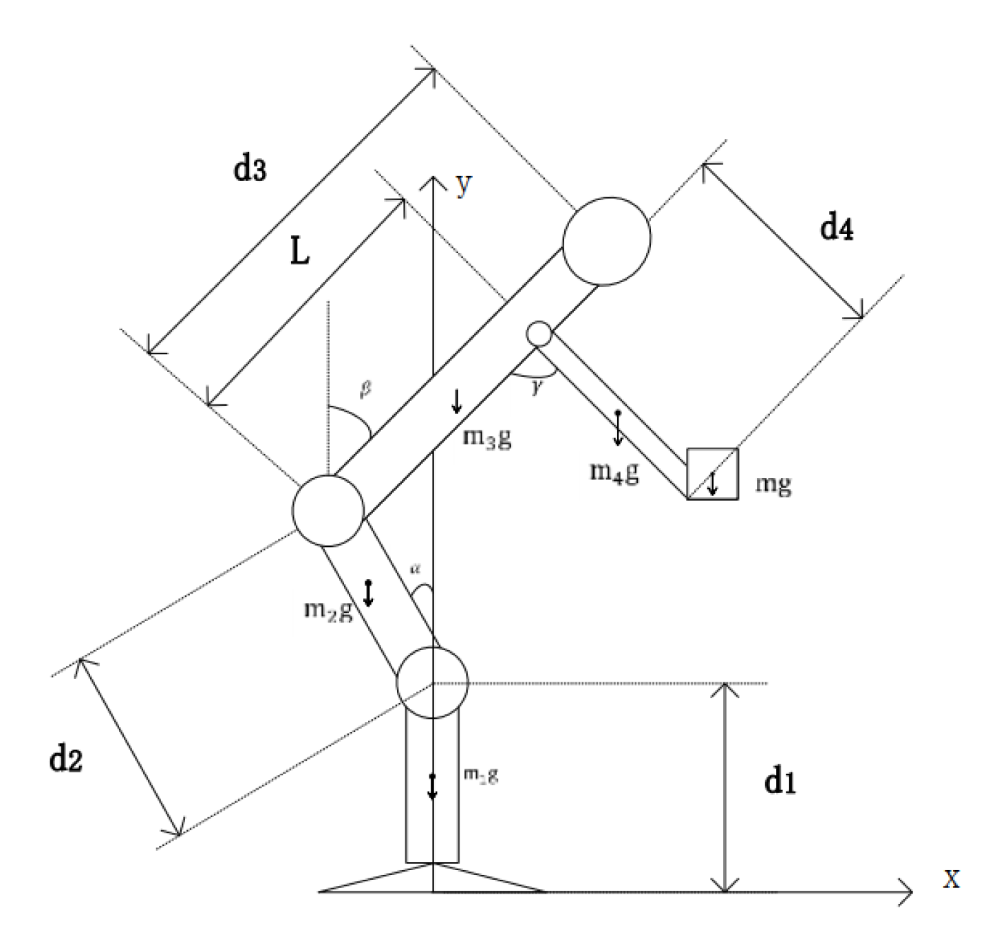
In the semi-squat movement, the upper arm and forearm are usually in a straight line, which can simplify the arm into a rigid body with even mass distribution. As shown in Figure 1, the length of the arm is . Since the weight is at the end of the arm, we assumed that the center of mass of the weight is on the same straight line with the center of mass of the arm, and merged the weight with the arm. The coordinates of the center of mass of the merged rod are as follows:
Compared with stoop and squat, semi-squat can help the body produce more torque when standing up, and it can also keep the center of gravity between the feet on the horizontal plane when lifting heavy objects, keeping the posture stable and reducing the risk of injury during lifting.
By defining the Lagrangian function and the Lagrangian formula, the inverse dynamics model of the hip joint in the process of semi-squat is established as follows:
where is the acceleration vector; is the angular velocity vector; and , where is the effective inertia of joint , is the coupling inertia between joint and , refers to the centripetal force generated by joint on joint with velocity , refers to the coeldrin force generated by joint acting on joint with velocity , and is the torque of the gravity term. According to the calculation formula of rigid body power , it can be obtained that the formula of the output power of the hip joint during the movement of human body is:
In the moment equation of hip joint, the moment formula of the gravity term is as follows:
where represents the distance between the shoulder turning point and the hip joint during manual handling, and the negative sign represents the direction of torque opposite to the specified direction. From the equation, we can find that the larger the bending angle, the greater the output torque of the hip joint when holding still. When the body is upright (), the hip joint ideally does not produce torque. However, the angular acceleration and angular velocity fluctuating up and down 0 can still be detected, which is not exactly equal to 0. Therefore, the back muscles and the hip joint still need to output torque to maintain the balance of the body.
During the hip active exoskeleton assisting human manual material handling, the exoskeleton and the human body together generate the required torque for the semi-squat; the actuation unit drives a mechanical structure that pushes the body’s thighs and upper body to assist the body stand up; at this point, the inverse dynamic equation of the hip joint becomes:
In Formula (7), is the actual torque required for the system to stand up, the output torque of the hip joint () and the output torque of the exoskeleton system () constitute the required torque during the semi-squat lifting. In the case of lifting the same weight and doing the same action, the mass of the exoskeleton is added to the human body, resulting in an increase in the required torque on each joint. Therefore, during the actuation unit selection, the actuation unit should be able to output a large enough torque to offset the additional torque caused by the mass of the exoskeleton.
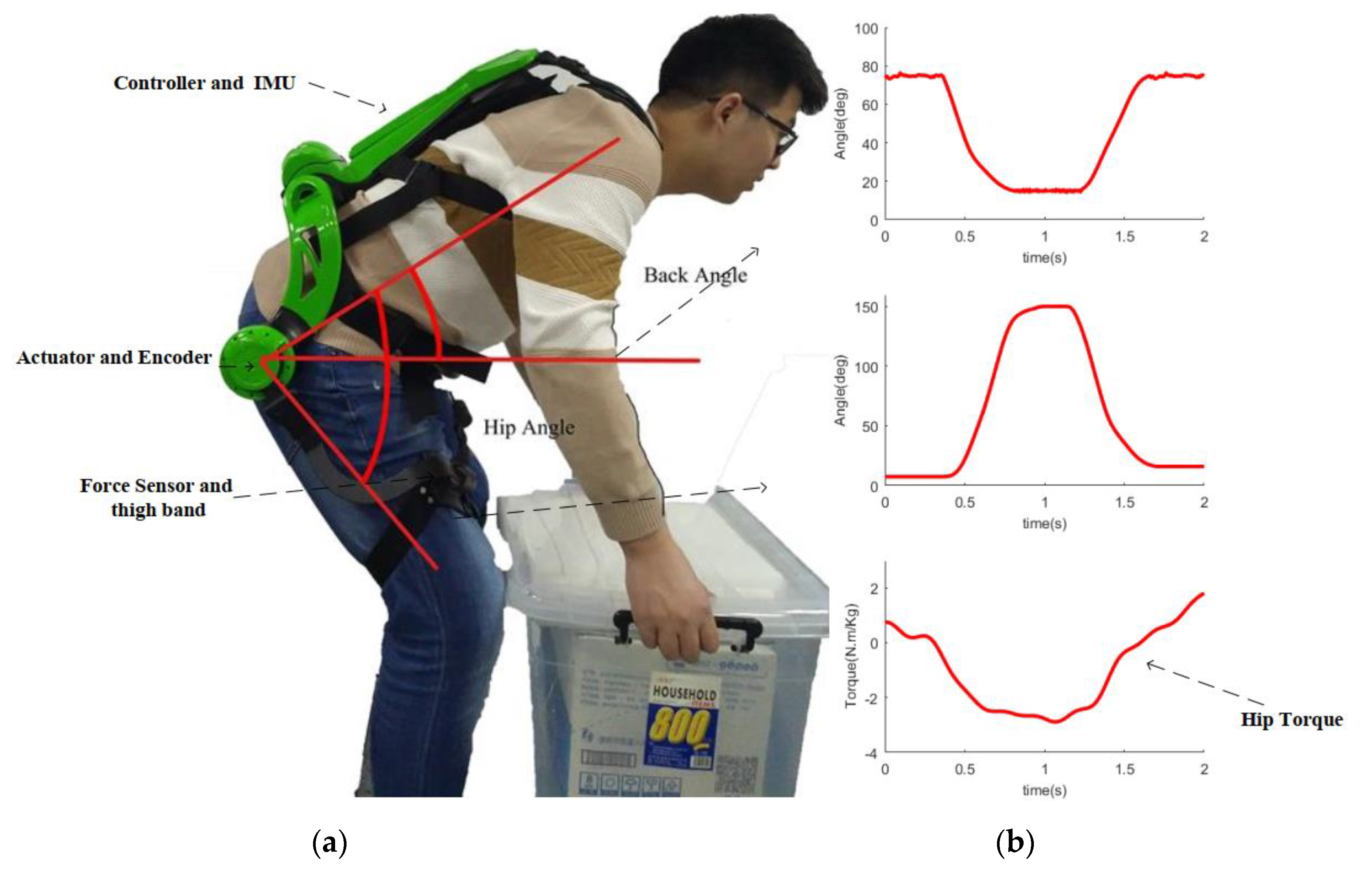
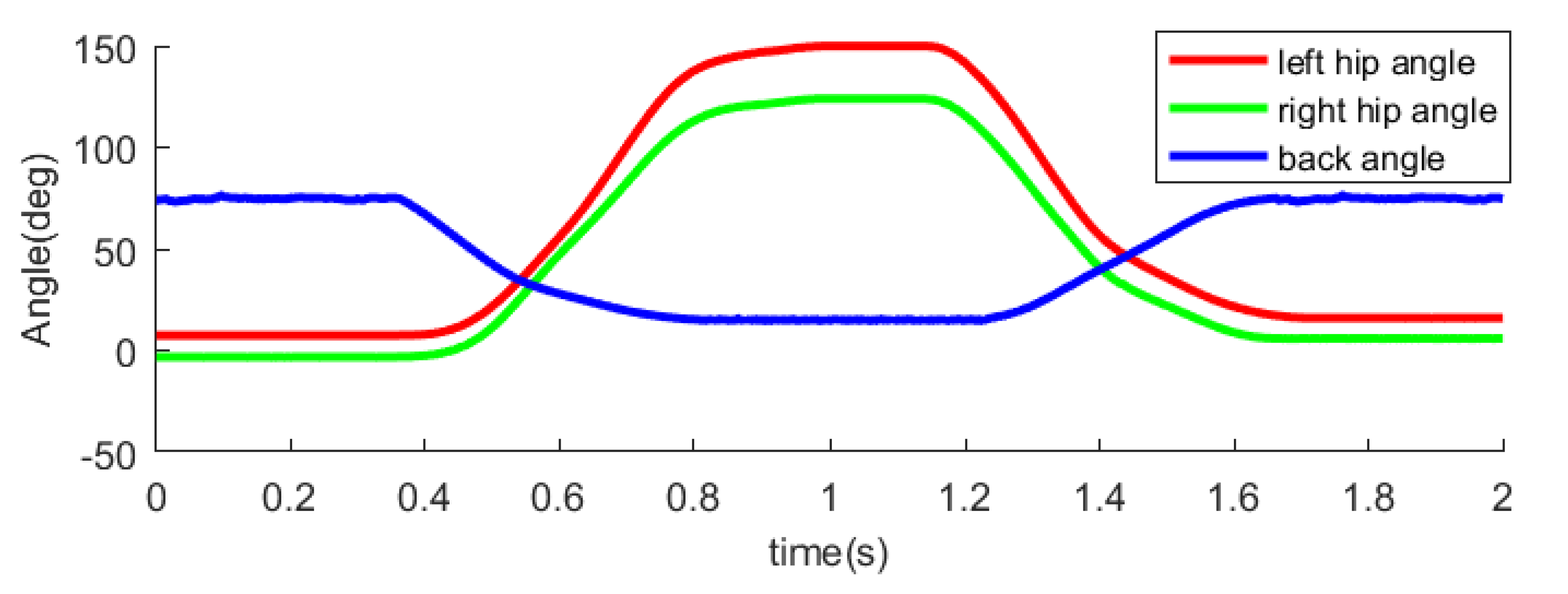
Due to the limitation of the sensor placement, the angle of the back and the angle of the hip measured is shown in Figure 2. The angle of the hip joint was defined as zero when standing upright, and the joint angle will increase when the subject bends. It can be found that at the peak of the hip joint angle, for an adult man, the hip joint output torque can reach minus 200 N.m. We can convert the data measured by the above sensors to the corresponding angle in Figure 1, and the conversion formula is as follows:
Combined with the actual measured hip angle of motion (Figure 2) and the average height and weight distribution of the adult male body, we can obtain the output torque and power of the lower hip by semi-squatting (Figure 3), which will be used in structure design and controller design. It can be found that when bending, the hip joint output negative work, and when standing up, the hip joint output positive work, help the human body to lift heavy objects.
2.2. Structure Design
2.2.1. Mechanical Structure Design
In this study, a hip active exoskeleton (Figure 4a) was designed and tested. The overall mass of the exoskeleton system is 6.2 kg. Compared to the other active assisted exoskeleton [19,20], which has a lighter mass (Model A weighs 6.7 kg, Kim’s exosuit weighs 7.5 kg) and most of the mass of the system is close to the center of mass of the wearer, the effect of the mass of the system on the wearer’s gait is minimized.
As can be seen from the torque output of the hip joint in Figure 2, the torque required by the hip joint in the semi-squat lift is close to 200 N.m, which is consistent with Luo, Z [23], Hemami, H [26] and Toxiri, S [28] et al. mentioned in their research. The combination of the harmonic reducer with a deceleration ratio of 101:1 and the external rotor dc brushless motor is adopted as the main part of the actuation unit, each single-side actuation unit can provide a torque of up to 80 N.m, leaving the rest to the human hip and back muscles. The actuation units are installed in parallel, the wearer can align the execution unit with the rotational center of the wearer’s hip joint by adjusting the binding structure of the shoulder and chest (Figure 4d). This makes the mechanical structure driven by the exoskeleton joint rotate in the same way as the human thigh, eliminating transmission efficiency loss caused by misalignment of the rotation center.
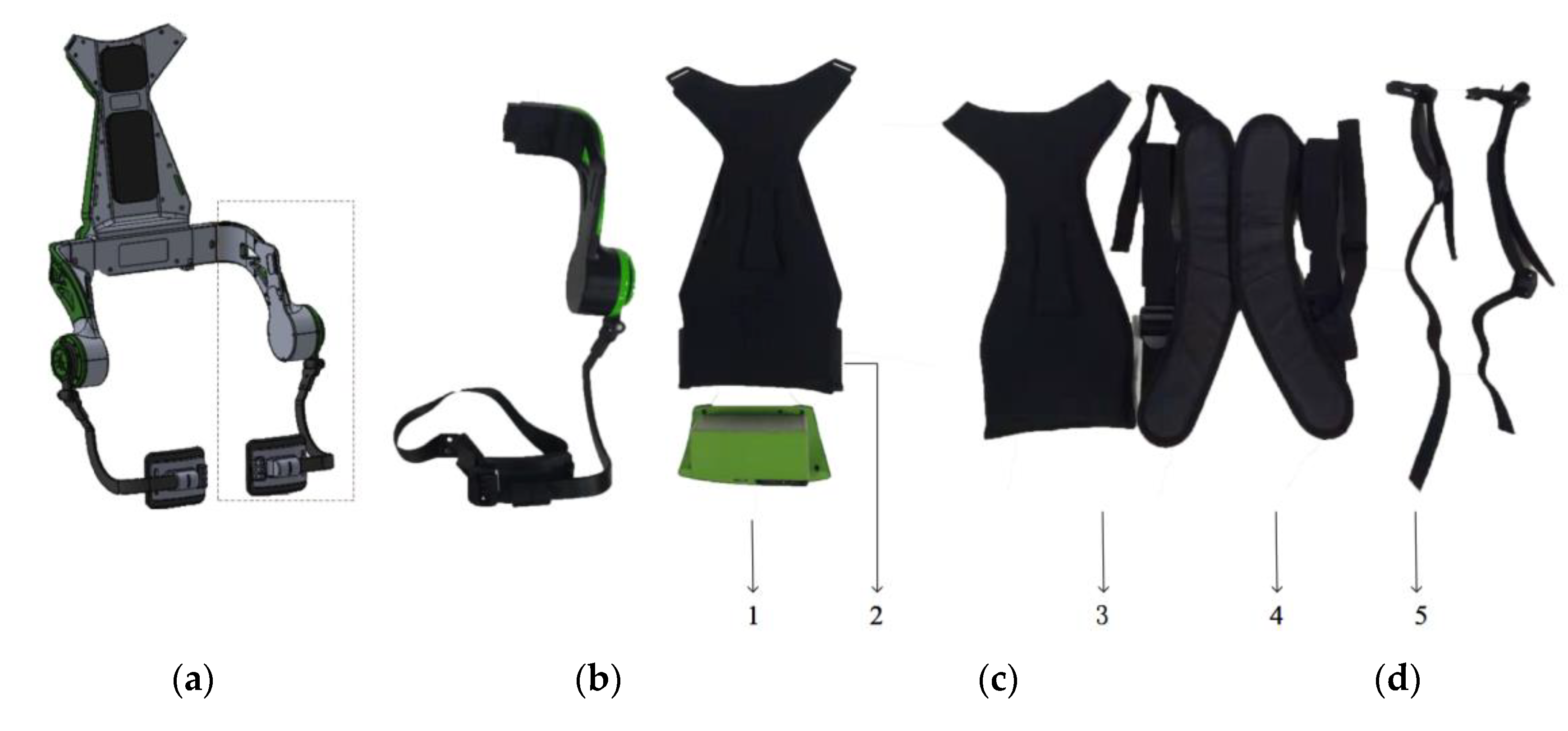
Briefly, the prototype is made of aluminum alloy and carbon fiber, extending from the human shoulder to the upper part of the knee. The mechanical structure is mainly composed of thigh rods (Figure 4b), a supporting mechanism at the waist (Figure 4c), and a binding structure (Figure 4d). The thigh rods on both sides each contain an actuation unit, which includes a brushless DC motor, harmonic drive gear and other flange accessories. A two-dimensional force sensor is added at the connection between the rotating rod of the actuator and the leg rod to detect the interactive force in the process of human motion. At the connection between the supporting mechanism of the thigh and the waist, a self-locking structure with an adjustable waist width of the system was designed to accommodate different users. Waist support mechanism mainly includes back-support plat, circuit board and battery (Figure 4c). The binding structure and thigh rods are connected to the waist support mechanism. In the binding structure, in order to fit the exoskeleton to the human body and align the actuation unit with the joint rotation center of the human body, the thigh, the waist, the shoulder, and the chest are added with adjustable binding bands (Figure 4-4,5). At the same time, in order to reduce the discomfort caused by the relative movement of the back, the removable cushion for leaning on was added to the back to improve the wearing comfort (Figure 4-3).
2.2.2. Electrical Structure Design
In order to accomplish the exoskeleton control scheme, sensors are not only placed on the back-support plate of the exoskeleton, but also on the actuation unit of the exoskeleton joint. Each exoskeleton joint is equipped with both kinematic (angular position, velocity and acceleration) and kinetic (interaction force between limb and exoskeleton) sensors. The hip exoskeleton operates with the following physical sensors:
- Absolute position magnetic encoders (AS5600) measure the joint angle at each joint output shaft.
- One IMU (Inertia Measurement Unit) (MPU6050) placed in the back-support plate to estimate the pitch angle of the upper body of the wearer.
- A force sensor at each powered joint is used to measure the interaction force between the body and the exoskeleton joint.
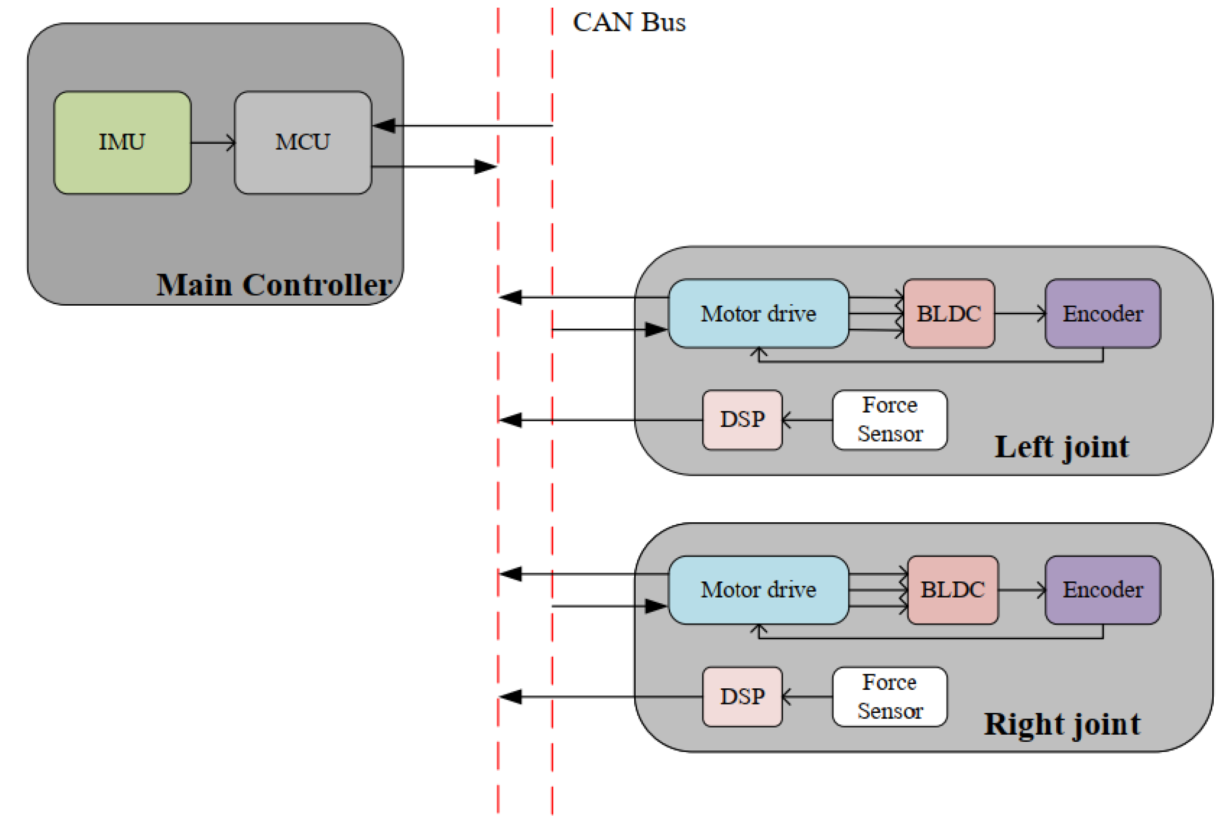
The electrical structure is the bridge connecting the control and mechanical structure in the system design, which mainly consists of three parts: the drive board at the left and right thighs and the main control board at the back. In addition to driving the motor and reading the encoder to obtain the current position, the driver board also puts DSP (Digital Signal Processing) to obtain the interactive force information output by the interactive force sensor during the movement. The instructions sent by the master, the actuator information and the interaction force information of the left and right leg joints are transmitted through CAN (Controller Area Network) communication (Figure 5), and the baud rate of its communication is 1000 K. During the movement, except for the sampling frequency of interaction force and the sampling resistance being 1K Hz, the rest of the sensor’s data update frequency is 200 Hz.
In the current state, the power is supplied by 24-V DC lithium batteries at the lower end of the back-support plat, with a maximum discharge current of up to 15 A. It can meet the maximum current required by the exoskeleton system to assist adult men (170 ± 10 cm, BMI (Body Mass Index) < 25) from squatting to standing.
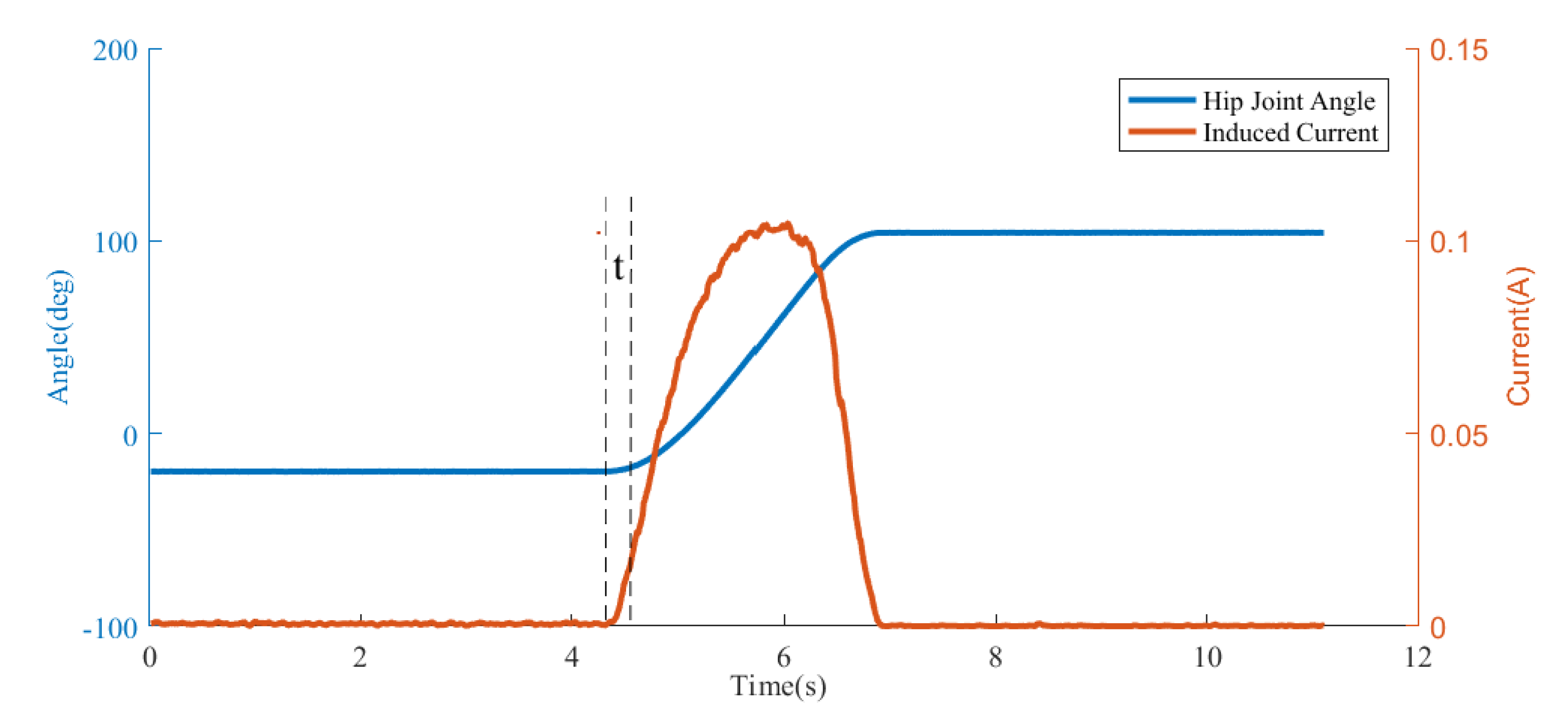
In particular, in addition to placing a sampling resistor on the lower bridge circuit of the three-phase inverter circuit of the motor driver, a sampling resistor is also placed on the bus of the driver for the collection and analysis of the induced current. The purpose of this is to make a quick judgment of the standing state, as can be seen from the Figure 6; when the subject wears the exoskeleton and moves in the EXO-OFF state, the induced current generated by the motor’s rotation of the human body changes faster than the angle obtained by the magnetic encoder, which can be used to solve the problem of rapidly capturing the motion intention of human body in the process of the human–computer interactive motion, so as to improve the subject’s sense of experience in the process of motion.
2.3. Controller Design
The exoskeleton described in this paper is a torque-controlled, back-supported exoskeleton driven by motors based on a power control strategy. The exoskeleton controller needs to perform two tasks, one is to keep the interactive force between the exoskeleton and the human body as little as possible in certain situations, such as walking and sitting. The other is to recognize the human semi-squat movement and assist the body to stand. Accordingly, the control strategy is divided into two parts. One is the real-time tracking of the Interactive moment signal, and the closed-loop feedback control of the output torque of the motor is adopted to keep the interaction force zero. In another control strategy, the required output torque is mainly determined based on the actual system joint rotational angular velocity and the output power of the hip joint in the semi-squat lifting.
2.3.1. Finite-State Machine
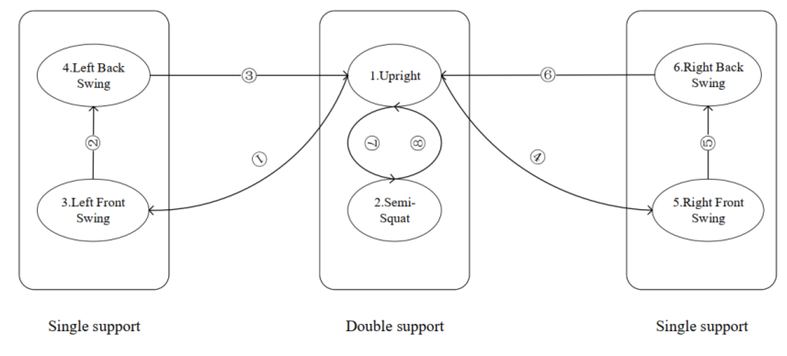
Six states are defined to describe the working state of the system: 1. upright state; 2. semi-squat state; 3. left leg forward swing, single foot support; 4. left leg backward swing, single foot support; 5. right leg forward swing, single foot support; and 6. right leg backward swing, single foot support. Each state corresponds to the motion characteristics of human joints. The main controller extracts the motion characteristics of human bodies and classifies to obtain the above human motion states.
The finite-state machine is shown in Figure 7. In the controller, the IMU on the back, the encoder, and the sampling resistor output data at the motor joint are used as the switching conditions of different state machines. The switching conditions between states are shown in Table 1. Since the magnetic encoder is installed on the shaft of the motor’s reduction gear, if only the angle sensor is used to detect the intention and posture of human motion, it will require the human body to drive the exoskeleton to detect the intention of motion, which will reduce the user’s wearing experience during the movement. When the method of detecting the current of the driver bus introduced in the electrical structure is used, the movement intention of the wearer can be quickly determined and the judgment time can be advanced (), which is shown in Figure 6.
2.3.2. Follow Control Strategy
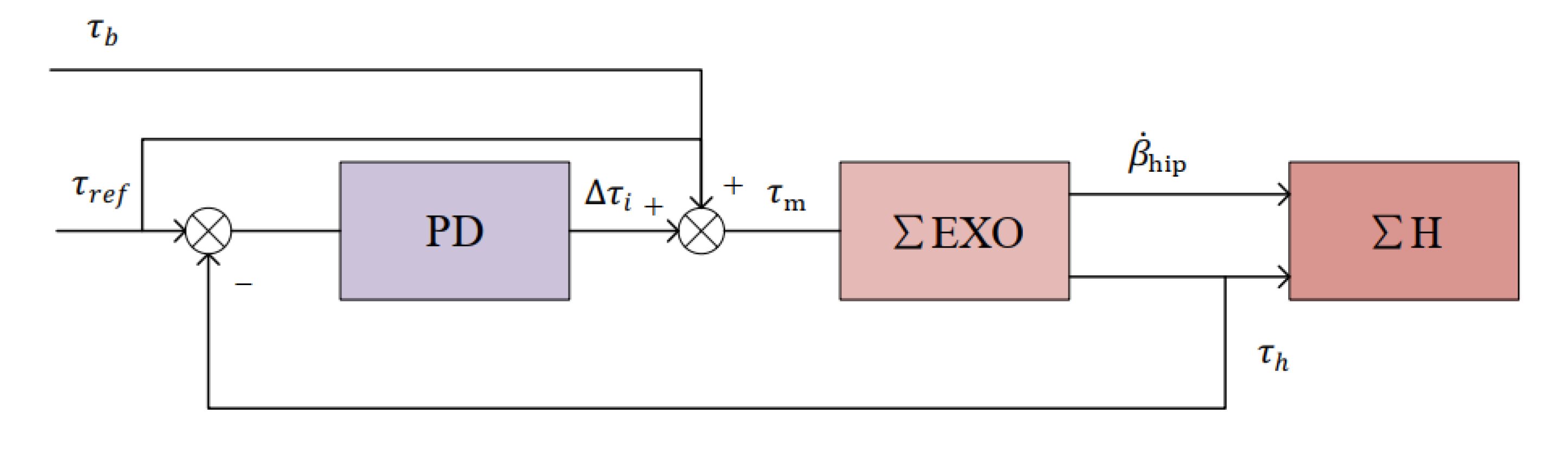
In the follow control strategy, the controller mainly controls the exoskeleton system to follow the movement of the human body. This requires the controller to continuously adjust the output torque of the actuator according to the man–machine interaction force data, so that the human–machine interaction force data received by the force sensor of the leg is kept near the target. In the follow control block diagram (Figure 8) and Formula (10), is the reference interaction moment and is set as 0 in the follow control strategy.
When the control system detects that the human body is not standing up, the power controller is closed. At this time, the torque of the system is obtained by the feedback control loop at the bottom. By introducing the interactive force into the negative feedback control loop, the reference moment of the dynamic solution during the control motion is constantly corrected and allows the wearer to perform his or her own movements without hindrance.
Without considering the motion of the human body, the formula for calculating the output torque of the follow-controlled exoskeleton joint is as follows:
The dynamic equation at the exoskeleton joint is as follows:
where is the internal rotational inertia of the motor, is the rotational inertia of the harmonic drive gear, is the deceleration ratio of the harmonic drive gear, and is the rotational inertia of the external member; refers the friction force generated when the body and the exoskeleton move side to side, and is the effective distance of the friction force from the revolute joint. represents the output torque due to the gravity of the thigh member, is the output torque of the motor operating in the torque mode, and is the interaction torque between the human and the exoskeleton. By measuring the real-time interaction force between the waist active exoskeleton and the wearer and introducing it into the closed-loop feedback control system, the system can be more stable and accurate.
2.3.3. Assist Control Strategy
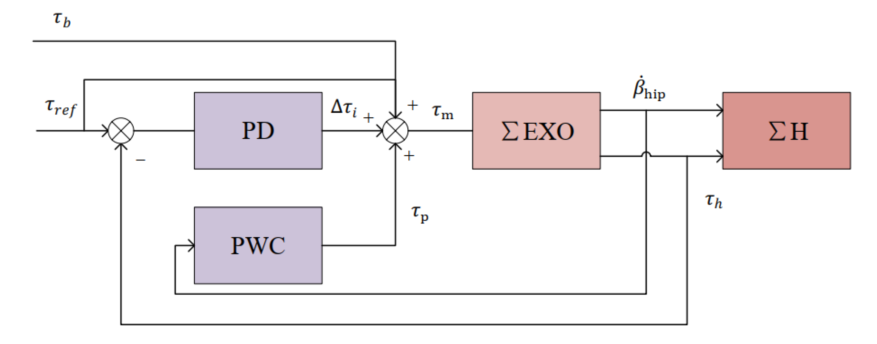
Based on complete and effective follow control, we have added a power controller to the follow control strategy. This means the control strategy can assist in manual material handling. The specific implementation is as follows: When the control system detects that the human body is standing up, the torque controlled by the power controller is introduced into the control loop (Figure 9).
The following control law is proposed, which includes a proportional-derivative torque feedback; a feed-forward action torque from inverse dynamics; and the power controller, where is the power function of the hip joint of the semi-squat lift of human body, and the expression is:
During the semi-squat lifting movement, the expression (14) combines the joint rotational speed and torque together, which is consistent with the actual man–machine coupling movement. When the human body joint rotation speed is faster than the hip exoskeleton, the human body in the active force and the exoskeleton system mainly follow the body movement. When the joint rotation of the human body is slow, the exoskeleton system will actively output the torque and help the human body achieve the semi-squat state to upright state. Therefore, the system can adapt the output torque according to the rotation speed of the human hip joint. is the hip power curve of the adult man at the moment of standing up calculated by the model in Section 2.1, the actuator at the exoskeleton joint cannot deliver such a high power, so the power curve solved by the original model is usually multiplied by a ratio in the control loop; the power function is multiplied by to make the torque output of the system conform to the torque variation trend of the semi-squat movement. In order to adapt to different ranges of motion, the motion angle data are normalized.
3. Evaluation Methods
In this study, seven healthy adult men (age 25 ± 3, weight 70 ± 5 kg, height 170 ± 3.0 cm) carried out experiments comparing carrying objects with and without an exoskeleton; the subjects signed an informed agreement and claimed to have had no lower back pain in the past 3 months. The experiment mainly measured the energy metabolism cost changes and the changes in the muscle electrical signals of the lower back during the continuous lifting process, to verify the effectiveness of the hip active assistance to the exoskeleton in assisting manual material handling.
In order to maintain the consistency of bending frequency and bending angle in the semi-squat reciprocating transportation, when subjects wore exoskeletons for comparison experiment, we added the function of indicating that the wearer had reached the given position in the system. The given position is as follows: The left and right bending angle of the hip is between 130 ° and 140° (), and the angle of the back from vertical is between 45° and 55° . Once the angle of the hip and back of the wearer reaches the desired position, the built-in buzzer indicates that the wearer has reached the desired position. After receiving the cue, the subject is required to lift the object autonomously with the assistance of the exoskeleton.
In the case of without-EXO, one IMU was placed on the upper body of the subjects and on the lateral sides of the left and right thighs of the subjects; there were also IMUs to detect the angle of pitch. By calculating the angle of pitch through Formulas (15)–(17), we could also detect the posture of the human body and give the subject prompts.
Before conducting the evaluation experiments, we first measured the data of sensors after the human body wore an exoskeleton to verify that the system could work normally. During the exoskeleton assisting manual material handling, both the follow control strategy and the assist control strategy are involved, therefore, we measured the sensor data of the subject during a complete handling movement to evaluate the performance of the exoskeleton system. The angle sensor data during the manual material handling, the motor output torque at different rising speeds, the interactive force under the follow control strategy, and the assist control strategy were recorded in this experiment. These data can help us better understand the working process of the exoskeleton.
3.1. Measure Metabolism Cost of Energy
To assess the reduced metabolic energy cost of the exoskeleton during assisted transport, a comparative experiment was conducted on three adults of different heights and weights (age 24 ± 3, weight 70 ± 5 kg, height 170 ± 5.0 cm). The specific experimental measurement methods and steps are as follows: First, participants were asked to wear portable gas analyzers (K4b2, Cosmed, Roma, Italy) and measure the base energy consumption while siting; due to the fact that K4b2 has the advantages of small size and light weight, it will not affect the range of motion of the human body after wearing and will not significantly increase the metabolism cost of human movement.
After being upright for 2 min, participants were asked to carry an 8 Kg weight from the ground back and forward to a platform at a height of 0.5 m, either with or without an exoskeleton. The whole process lasts 5 min. The carrying posture and frequency of the wearer during the carrying process are strictly controlled to reduce the influence of movement differences between participants on the experimental data. The whole process was repeated six times, three times without the exoskeleton, three times with the exoskeleton. The experiment was conducted 2 h after a meal to eliminate the effect of digestion on the metabolism cost of energy. To eliminate individual differences, data for each participant were normalized according to their own weight.
In this experiment, the K4b2 samples and analyzes the exhaled air of the human body, and the supporting software receives the energy consumption data and visualization through wireless transmission. After the experiment, the test data for each subject was processed by a MATLAB (The MathWorks Inc., Natrick, MA, USA) script to calculate the final metabolic cost of energy.
3.2. Measure Back Muscle Electromyography Signal
The purpose of the EMG measurement Experiment was to evaluate the reduced activity of the exoskeleton on the muscles of the lower back and analyze the effectiveness of the exoskeleton from another perspective. The areas where the electrical signals of the muscles of the lower back change significantly during semi-squat are mainly located in the erector spines and multifidus muscle on the left and right sides of the spine [29]. The erector spines are far away from the spine and produce a greater torque when the lumbar spine is stretched. The multifid muscle, which is usually attached to the lumbar spine, accounts for a quarter of the energy contribution of the trunk extensor during maximum trunk stretching [30]. As the handling quality becomes heavier, the amplitudes of EMG signals of the erector spines and multifidus muscle increase [31,32].
The specific experimental methods are as follows: Before the experiment began, Ag/AgCl surface electrodes were installed at the left thorax lumbar erector spinae, the right thorax lumbar erector spinae, the left thorax thoracic erector spinae, and the right thorax thoracic erector spinae after rubbing with alcohol at the test point of the subject’s back. The test point is based on Hermens et al. [11]; EMG signals were first measured at the test point in the standing position. The subjects were required to relax their back muscles before the experiment began. After it was detected that the back muscles EMG signals remained stable and the amplitude was near 0 for 10 s, a complete carrying movement experiment started. The EMG signal was not recorded during the bending of the subject. While the subject bent down to reach the established semi-squat posture, the left and right bending angle of the hip was between 130° and 140° (), and the angle of the back from vertical was between 45° and 55° . The posture capture system would indicate the wearer. After receiving the cue, the wearer began to lift the object, and another participant used the NORAXON EMG software to record the EMG signal data of the wearer.
In this experiment, seven subjects were asked to stand in a designated position and carry an 8 kg weight to a 0.5 m platform at a fixed frequency. In another set of experiments, subjects were asked to lift the same weight with the help of hip exoskeleton; the starting position and frequency of the semi-squat were the same as those without the exoskeleton. The only difference between the experiments is whether the subjects wore an exoskeleton or not.
4. Results
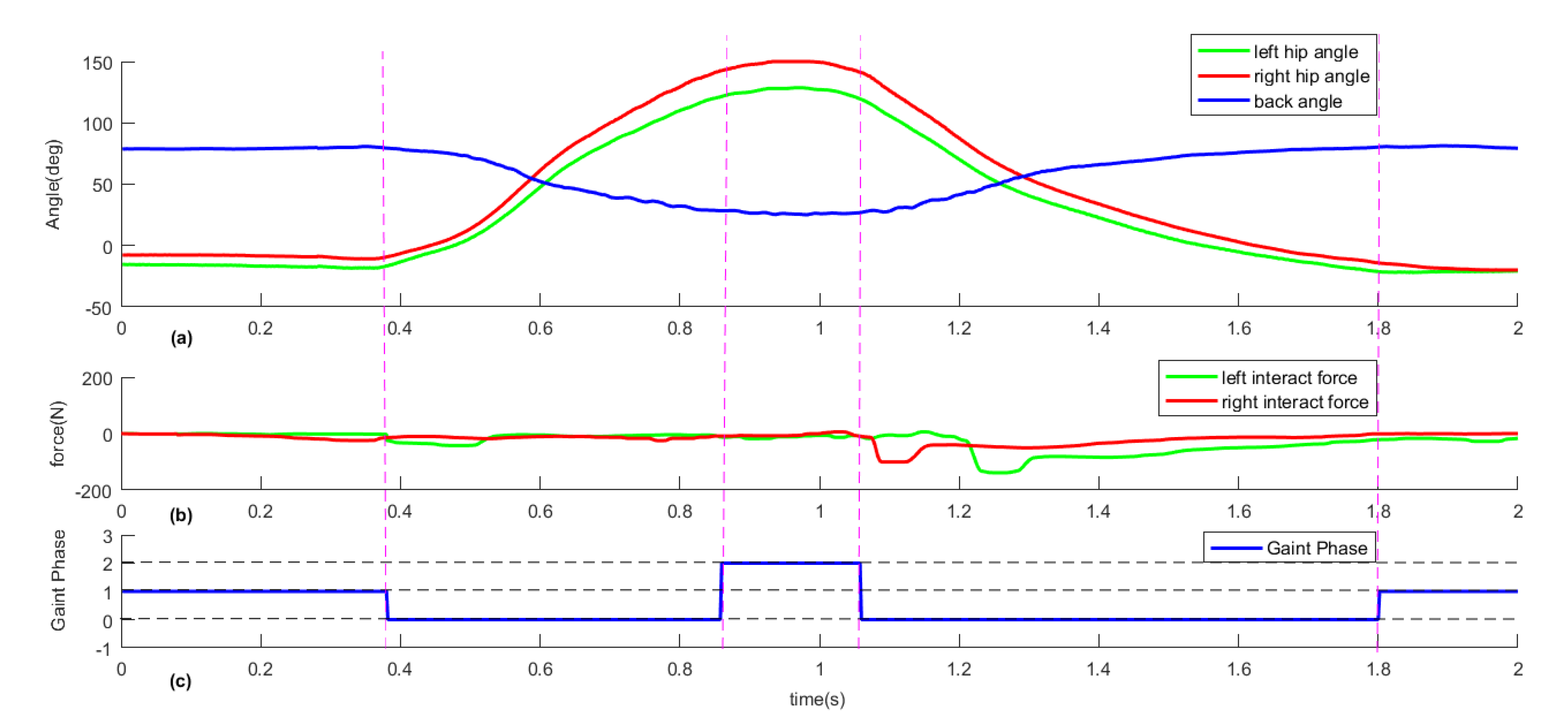
The sensor data images when the system is running are shown in Figure 10, Figure 11 and Figure 12. Comparing the movement angle curves of the joints when carrying heavy objects, we can find that the movement angle curves of the joints (the Figure 10 and the Figure 11a) have not changed significantly with or without the assistance of the exoskeleton during the process of lifting heavy objects, which means that no mechanical and control interference affect the carrier’s manual material handling.
In the gait phase of Figure 11c, the system distinguishes between semi-squat and upright. The definition of gait phase is consistent with the definition of finite state machine. Since the transition of the human body in semi-squat and upright is not realized immediately, we define the transition process state of the two states as 0. The controller can further distinguish between bending and standing up according to the slope of the angle sensor data and assist the human body to get up.
As can be seen in Figure 12, turns out that under different joint angular velocities, the output torque of the exoskeleton hip joint changes with the angular velocity of the human body when the subject is standing up. The controller system calculates the torque of the exoskeleton hip joint based on the angular velocity. It can be found that when the movement is fast, the output torque of the joint is small; compared with when the movement speed is slow, the average output torque of the joint is smaller and the peak torque lasts shorter.
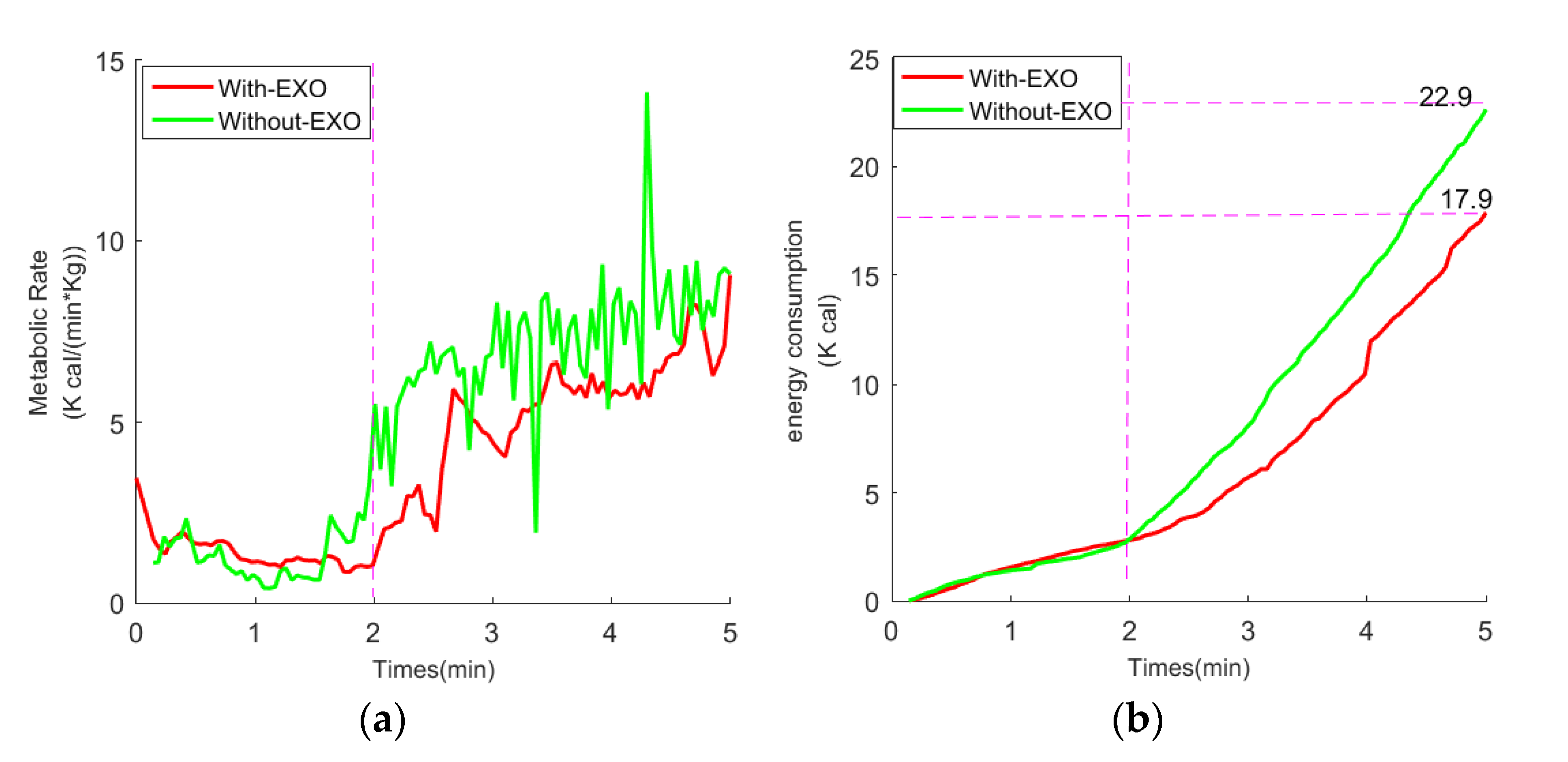
In the experiment of detecting the metabolism cost of energy in the state of continuous transportation, the energy consumption of the subject’s continuous transportation with or without an exoskeleton was recorded and subtracted from the basic metabolism cost of energy. Figure 13 shows the change of energy consumption with time under the state of continuous transportation; the results showed that wearing the exoskeleton upright did not significantly increase the overall energy consumption, while during the reciprocating process, the total energy consumption of the carrier decreased by 18% (n = 3, two-sided paired t tests, p = 0.091 < 0.01).
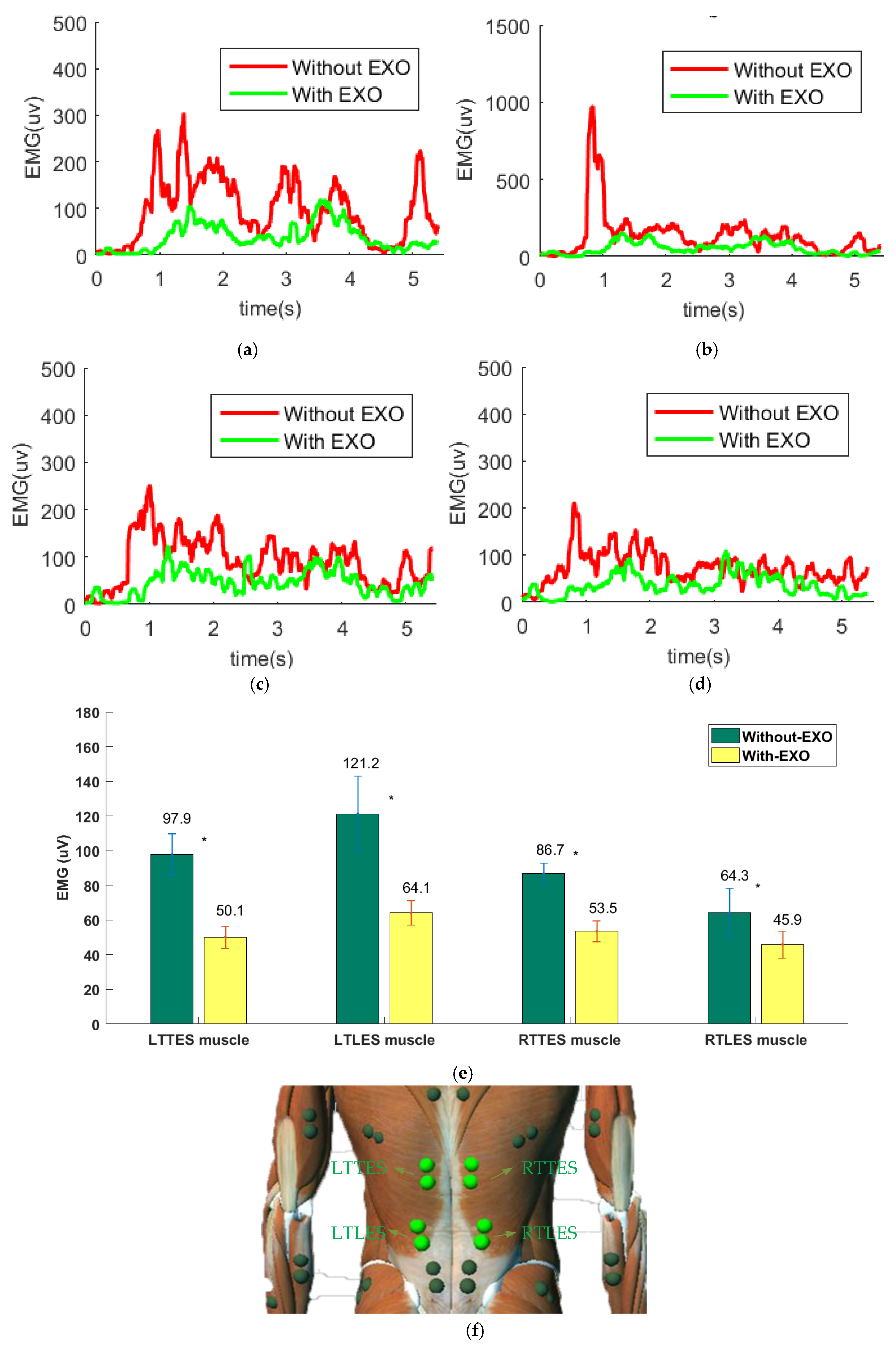
After rectifying the original EMG signal and low-pass (10–400 Hz) filtering, the root mean square (RMS) value was calculated for the EMG signal every 5 ms, and the EMG signal amplitude of the muscle group is shown in Figure 14a–d, respectively; the mean EMG amplitude in four muscle groups is shown in Figure 14e. Comparing the EMG signals of the erector spinae with or without exoskeleton assistance during transport, we found that the activity of EMG signals without exoskeletons was significantly higher than with exoskeleton assistance. Specifically, there was a 48% (without 97.9 ± 11.9 and with 50.1 ± 6.4 , n = 7, two-sided paired t tests, p = 0 < 0.05) reduction of muscle activity for the LTTES (Left Thorax Thoracic Erector Spinae), a 47% (without 121.2 ± 21.8 and with 64.1 ± 7.04 , n = 7, two-sided paired t tests, p = 0 < 0.05) reduction for the LTLES (Left Thorax Lumbar Erector Spinae), a 37% (without 86.7 ± 6.0 and with 53.5 ± 6.01 , n = 7, two-sided paired t tests, p = 0 < 0.05) reduction for the RTTES (Right Thorax Thoracic Erector Spinae), and a 30% (without 64.3 ± 14.1 and with 45.9 ± 7.8 , n = 7, two-sided paired t tests, p = 0.001 < 0.05) reduction for the RTLES (Right Thorax Lumbar Erector Spinae) with the exoskeleton (compared to without-EXO).
5. Discussion
Compared to a passive exoskeleton, active exoskeleton can provide variable torque, which enables the system to work in more complex environments. In this paper, the proposed hip active exoskeleton is designed to assist the human body with optimal handling techniques. The system will automatically adjust the joint output torque according to the joint rotation angular velocity of the carrier during the transportation process. At the same time, it can be found from the angle sensor data and the interaction force sensor data that the exoskeleton in the paper prolongs the rise time of the human body. Comparative experiments show that in the situation without exoskeletons, the subjects lifting and bending movements will cause the waist back EMG signal to rise and fall sharply, and the average amplitude of the signal will be greater. With the help of an exoskeleton, the average amplitude of the EMG signal of the wearer’s back muscle group decreases and changes gently. This means that the absence of exoskeleton assistance during the subjects’ manual material handing will cause the center frequency of myoelectric signals to increase. Subjects stated that during the assist process, the subject’s thighs and shoulders were pushed by the system, so the back muscles and hip joints did not need to output the corresponding torque when bending without an exoskeleton. According to the characteristics of average amplitude increase of EMG signal during muscle fatigue [33], it can be inferred that this exoskeleton can effectively reduce the activity of the muscles in the lower back and extend the endurance of the human body for reciprocating transport.
Analysis of the interaction force sensor data shows that when the human body is not standing up, the interaction force between the human and the machine is generally controlled near 0; however, when the system detects that the human body is up, the power controller will control the system output torque based on the human body’s motion data. The interaction force reaches peaks and then decreases negatively exponentially. The figure shows that the interaction force between the human and the machine does not increase immediately after the controller recognizes the human body’s standing up movement. There is also a delay in the time between the left and right legs of the human body beginning to receive exoskeleton assistance (approximately 100 ms). This is due to the angle difference between the exoskeleton and the human body, which is mainly caused by the inconsistency of the tightness of the left and right legs and the types of sensors used in the exoskeleton. Therefore, the interaction force sensor does not increase immediately as the system first compensates the human–machine angle difference when assisting the human body to stand up. A close-fitting binding structure can help to reduce the time delay of the angle difference in the movement and improve the physical feeling when wearing the exoskeleton.
Exoskeleton, as a type of bionic robot, often has a time delay with the human body during the human–machine coupling movement, which is not only related to machinery and binding structure, but also related to system cognition speed. The type of sensor used in the exoskeleton will greatly affect the speed of the system’s cognition. The current system uses sensors to detect the posture of the exoskeleton, which has the advantages of small number, convenient installation and stable work. However, since the human body is required to drive the exoskeleton at the beginning of the movement, there is inevitably a time delay with the human body during the human–machine coupling movement. Moreover, motor performance deficits in older adults may be due to motor impairments, not cognitive impairments. STAC (Scaffolding Theory of Aging and Cognition) suggests that pervasive increased frontal activation with age is a marker of an adaptive brain, which engages in cognitive compensation in response to the challenges posed by declining neural structures and function [34]. One evidence from an orthoptera–robot interaction shows that cognitive decline does not occur in locusts with age [35], whereas motor impairments occur more frequently with age. This means that if the exoskeleton movement is controlled by collecting EEG signals, which has the advantages of not being easily affected by the physical condition of the wearer and reducing the time delay in man–machine coupling movement, this will be more in line with the needs of the elderly or disabled. On the other hand, the scope of the applicable population by placing sensors on the exoskeleton can also be increased if the prediction of aperiodic motion sensor data can be realized, which is also a kind of cognitive compensation for human movement.
However, our hip active exoskeleton is committed to assisting in carrying and following human movement with small hindrance, which still has limitations. One is that there is an asymmetric handling condition in the handling process, which makes the transporter need to rotate the upper body in the handling process, and the output torque of the left and right hip joints is not consistent, which is not achieved in the mechanical structure and control of our existing exoskeleton prototype. Second, in the process of auxiliary transportation, the prototype can only give assistance to the wearer when standing up, while the rest of the time it follows the movement of the human body. We found that the EMG signals of the lower back were also active when bending. Therefore, in the subsequent design, we considered adding the function of assisting in bending to the exoskeleton prototype rather than just assisting in lifting heavy objects.
6. Conclusions
We analyzed the output torque and power of the hip joint of the semi-squat lift on the basis that the semi-squat lift is a better handling technique for the human body. A hip active exoskeleton system was designed based on the power output curve of the hip joint during human semi-squat lifting. Since the torque of the system is determined by the angular velocity of the human body’s motion and the power of the hip joint, the exoskeleton can be adaptive to the output torque when assisting human transport.
With the assistance of the hip active exoskeleton, the amplitude of the back muscles of the erector spinae decreases, and the magnitude of the torque of the hip joint is reflected by the magnitude of the EMG signal amplitude of the waist. Therefore, we hypothesized that the active hip exoskeleton assisted manual lifting mainly by reducing the activity of the myoelectric signals in the lower back to reduce the risk of lower back injury. From the experimental data, there is no doubt that the active exoskeleton can assist the human body in semi-squat lifting, and by reducing the activity of the muscles in the lower back, the exoskeleton may also reduce the risk of lower back injury.
Author Contributions
W.W. conceived of the presented idea. S.Z. and W.W. developed the theoretical formalism. S.Z. collected and analyzed the data. Y.X. developed the mechanical structure and electrical structure. S.Z. designed the control system. S.Z. and X.L. discussed the result and wrote the paper. W.W. and J.G. supervised the entire work. All authors have read and agreed to the published version of the manuscript.
Funding
This research is partly supported by Natural Science Research General Program of Higher Education of Jiangsu Province (16KJB510040).
Acknowledgments
We would like to thank Wei Wang and Zhicheng Qu for the help with software and controller design.
Conflicts of Interest
The authors declare that there is no conflict of interests regarding the publication of this paper.
References
- Hoy, D.; Brooks, P.; Blyth, F.; Buchbinder, R. The Epidemiology of low back pain. Best Pract. Res. Clin. Rheumatol. 2010, 24, 769–781. [Google Scholar] [CrossRef]
- Griffith, L.E.; Shannon, H.S.; Wells, R.P.; Walter, S.D.; Cole, D.C.; Côté, P.; Frank, J.; Hogg-Johnson, S.; Langlois, L.E. Individual Participant Data Meta-Analysis of Mechanical Workplace Risk Factors and Low Back Pain. Am. J. Public Health 2012, 102, 309–318. [Google Scholar] [CrossRef]
- Munch Nielsen, C.; Gupta, N.; Knudsen, L.E.; Holtermann, A. Association of objectively measured occupational walking and standing still with low back pain: A cross-sectional study. Ergonomics 2016, 60, 118–126. [Google Scholar] [CrossRef]
- Breivik, H.; Collett, B.; Ventafridda, V.; Cohen, R.; Gallacher, D. Survey of chronic pain in Europe: Prevalence, impact on daily life, and treatment. Eur. J. Pain 2006, 10, 287. [Google Scholar] [CrossRef]
- Langley, P.C. The prevalence, correlates and treatment of pain in the European Union. Curr. Med Res. Opin. 2011, 27, 463–480. [Google Scholar] [CrossRef]
- Dagenais, S.; Caro, J.; Haldeman, S. A systematic review of low back pain cost of illness studies in the United States and internationally. Spine J. 2008, 8, 8–20. [Google Scholar] [CrossRef]
- Wang, Z. Experimental Study on Manual Lifting Techniques and Fatigue Recovery. Ph.D. Thesis, Huazhong University of Science and Technology, Wuhan, China, 2009. [Google Scholar]
- Burgess-Limerick, R.; Abernethy, B. Toward a Quantitative Definition of Manual Lifting Postures. Hum. Factors J. Hum. Factors Ergon. Soc. 1997, 39, 141–148. [Google Scholar] [CrossRef]
- Jing, C.; Lei, Y.; Jiasun, D.; Zhenglun, W. The Application of Surface Electromyography in Assessing Ergonomic Risk Factors Associated with Manual Lifting Tasks. J. Huazhong Univ. Sci. Technol. Med Sci. 2004, 24, 552–555. [Google Scholar] [CrossRef]
- Straker, L.; Duncan, P. Psychophysical and psychological comparison of squat and stoop lifting by young females. Aust. J. Physiother. 2000, 46, 27–32. [Google Scholar] [CrossRef]
- Bosch, T.; van Eck, J.; Knitel, K.; de Looze, M. The effects of a passive exoskeleton on muscle activity, discomfort and endurance time in forward bending work. Appl. Ergon. 2016, 54, 212–217. [Google Scholar] [CrossRef]
- Ito, T.; Ayusawa, K.; Yoshida, E.; Kobayashi, H. Stationary torque replacement for evaluation of active assistive devices using humanoid. In Proceedings of the 2016 IEEE-RAS 16th International Conference on Humanoid Robots (Humanoids) (IEEE), Cancun, Mexico, 15–17 November 2016. [Google Scholar] [CrossRef]
- Wei, W.; Wang, W.; Qu, Z.; Gu, J.; Lin, X.; Yue, C. The effects of a passive exoskeleton on muscle activity and metabolic cost of energy. Adv. Robot. 2020, 34, 1–9. [Google Scholar] [CrossRef]
- Abdoli-E, M.; Agnew, M.J.; Stevenson, J.M. An on-body personal lift augmentation device (plad) reduces emg amplitude of erector spinae during lifting tasks. Clin. Biomech. 2006, 21, 456–465. [Google Scholar] [CrossRef]
- Wehner, M.; Rempel, D.; Kazerooni, H. Lower Extremity Exoskeleton Reduces Back Forces in Lifting. In Asme Dynamic Systems & Control Conference; ASME: New York, NY, USA, 2009. [Google Scholar] [CrossRef]
- Ulrey, B.L.; Fathallah, F.A. Subject-specific, whole-body models of the stooped posture with a personal weight transfer device. J. Electromyogr. Kinesiol. 2003, 23, 206–215. [Google Scholar] [CrossRef]
- De Rijcke, L.; Näf, M.; Rodriguez-Guerrero, C.; Graimann, B.; Houdijk, H.; van Dieën, J.; Mombaur, K.; Russold, M.; Sarabon, N.; Babič, J.; et al. Spexor: Towards a passive spinal exoskeleton. In Wearable Robotics: Challenges and Trends; Springer: Cham, Switzerland, 2007. [Google Scholar] [CrossRef]
- Naf, M.B.; Rijcke, L.D.; Rodriguez-Guerrero, C.; Millard, M.; Lefeber, D. Towards low back support with a passive biomimetic exo-spine. In Proceedings of the IEEE International Conference on Rehabilitation Robotics, London, UK, 17–20 July 2007. [Google Scholar] [CrossRef]
- Nasiri, R.; Ahmadi, A.; Ahmadabadi, M.N. Reducing the Energy Cost of Human Running Using an Unpowered Exoskeleton. IEEE Trans. Neural Syst. Rehabil. Eng. 2018, 10, 2026–2032. [Google Scholar] [CrossRef]
- Wesslén, J. Exoskeleton Exploration: Research, Development, and Applicability of Industrial Exoskeletons in the Automotive Industry. Master’s Thesis, School of Engineering in Jönköping, Jönköping, Sweden, 2018. [Google Scholar]
- Aida, T.; Nozaki, H.; Kobayashi, H. Development of muscle suit and application to factory laborers. In Proceedings of the IEEE International Conference on Mechatronics and Automation (ICMA), Changchun, China, 9–12 August 2009; pp. 1027–1032. [Google Scholar]
- Hara, H.; Sankai, Y. Development of HAL for lumbar support. In Proceedings of the SCIS and ISIS 2010-Joint 5th International Conference on Soft Computing and Intelligent Systems and 11th International Symposium on Advanced Intelligent Systems, Okayama, Japan, 8–12 December 2010; pp. 416–421. [Google Scholar] [CrossRef]
- Luo, Z.; Yu, Y. Wearable stooping-assist device in reducing risk of low back disorders during stooped work. In Proceedings of the 2013 IEEE International Conference on Mechatronics and Automation, IEEE ICMA, Takamatsu, Japan, 4–7 August 2013; pp. 230–236. [Google Scholar] [CrossRef]
- Zhao, Y. Ergonomics basic data investigation and research. Ergonomics 2013, 19, 76–79. [Google Scholar]
- Chehrehrazi, M.; Sanjari, M.A.; Mokhtarinia, H.R.; Jamshidi, A.A.; Maroufi, N.; Parnianpour, M. Goal equivalent manifold analysis of task performance in non-specific LBP and healthy subjects during repetitive trunk movement: Effect of load, velocity, symmetry. Hum. Mov. Sci. 2017, 51, 72–81. [Google Scholar] [CrossRef]
- Hemami, H.; Jaswa, V.C. On a Three-Link Model of the Dynamics of Standing up and Sitting down. IEEE Trans. Syst. Man Cybern. 1978, 8, 115–120. [Google Scholar] [CrossRef]
- Hanavan, E.P., Jr. A Mathematical Model of the Human Body; Air Force Aerospace Medical Research Lab Wright-Patterson AFB: Wright, OH, USA, 1964. [Google Scholar]
- Toxiri, S.; Calanca, A.; Ortiz, J.; Fiorini, P.; Caldwell, D.G. A Parallel-Elastic Actuator for a Torque-Controlled Back-Support Exoskeleton. IEEE Robot. Autom. Lett. 2017, 1, 492–499. [Google Scholar] [CrossRef]
- Wehner, M.; Rempel, D.; Kazerooni, H. Lower Extremity Exoskeleton Reduces Back Forces in Lifting. In Proceedings of the Asme Dynamic Systems & Control Conference, Hollywood, CA, USA, 12–14 October 2009. [Google Scholar] [CrossRef]
- Bogduk, N.; Macintosh, J.E.; Pearcy, M.J. A Universal Model of the Lumbar Back Muscles in the Upright Position. Spine 1992, 17, 897–913. [Google Scholar] [CrossRef]
- Ferguson, S.A.; Marras, W.S.; Burr, D. Workplace design guidelines for asymptomatic vs. low-back-injured workers. Appl. Ergon. 2005, 36, 85–95. [Google Scholar] [CrossRef]
- Granata, K.P.; Marras, W.S. Cost–Benefit of Muscle Cocontraction in Protecting against Spinal Instability. Spine 2000, 25, 1398–1404. [Google Scholar] [CrossRef] [PubMed]
- Potvin, J.R.; Bent, L.R. A validation of techniques using surface EMG signals from dynamic contractions to quantify muscle fatigue during repetitive tasks. J. Electromyogr. Kinesiol. 1997, 7, 131–139. [Google Scholar] [CrossRef]
- Park, D.C.; Reuter-Lorenz, P. The adaptive brain: Aging and neurocognitive scaffolding. Annu. Rev. Psychol. 2009, 60, 173–196. [Google Scholar] [CrossRef] [PubMed] [Green Version]
- Romano, D.; Bloemberg, J.; Tannous, M.; Stefanini, C. Impact of Aging and Cognitive Mechanisms on High-Speed Motor Activation Patterns: Evidence from an Orthoptera-Robot Interaction. IEEE Trans. Med. Robot. Bionics 2020. [Google Scholar] [CrossRef]
Figure 1.
Simplified model of rigid body in semi-squat.

Figure 2.
(a) The current version of the prototype exoskeleton. (b) The angle and hip output torque measured by the subject during the semi-squat.
Figure 2.
(a) The current version of the prototype exoskeleton. (b) The angle and hip output torque measured by the subject during the semi-squat.

Figure 3.
Curve of hip joint power output during semi-squat.

Figure 4.
The hip active exoskeleton ‘MeBot-EXO’. (a) Prototype in SolidWorks. (b) Thigh member. (c) Supporting mechanism of the waist. (d) Binding structure. 1. Battery. 2. Back-support plate. 3. Removable cushion. 4. Shoulder straps. 5. Waist straps.
Figure 4.
The hip active exoskeleton ‘MeBot-EXO’. (a) Prototype in SolidWorks. (b) Thigh member. (c) Supporting mechanism of the waist. (d) Binding structure. 1. Battery. 2. Back-support plate. 3. Removable cushion. 4. Shoulder straps. 5. Waist straps.

Figure 5.
Electrical hardware structure.

Figure 6.
Curve of induced current and angle in EXO-OFF state.

Figure 7.
Finite-state machine.

Figure 8.
Follow control block diagram.

Figure 9.
Assist control block diagram.

Figure 10.
Manual material handling without exoskeleton sensor data.

Figure 11.
The result of the control system recognizing the posture of the human body. (a) Manual material handling assisted by exoskeleton angle sensor data. (b) Interact force during manual material handling. (c) Gait phase in manual material handling.
Figure 11.
The result of the control system recognizing the posture of the human body. (a) Manual material handling assisted by exoskeleton angle sensor data. (b) Interact force during manual material handling. (c) Gait phase in manual material handling.

Figure 12.
Actuator output torque at different speeds when standing up.

Figure 13.
Metabolic cost of energy during the continuous manual material handling with and without exoskeleton. (a) Metabolic Rate in 5 min. (b) Metabolic cost of energy in 5 min.
Figure 13.
Metabolic cost of energy during the continuous manual material handling with and without exoskeleton. (a) Metabolic Rate in 5 min. (b) Metabolic cost of energy in 5 min.

Figure 14.
EMG amplitude of four muscle groups at L5/S1 location: (a) LTTES muscle amplitude in 5 s. (b) LTLES muscle amplitude in 5 s. (c) RTTES muscle amplitude in 5 s. (d) RTLES muscle amplitude in 5 s. (e) The median EMG activities of four muscle groups (Error bars indicate standard deviation. Significant results (p < 0.05) are marked with an *). (f) Four muscle group locations.


Table 1.
Finite-state machine transition conditions.
| # | Transition Conditions | Next State Machine | |
|---|---|---|---|
| ① | 3.Left Front Swing | ||
| ② | 4.Left Back Swing | ||
| ③ | 1.Upright | ||
| ④ | 5.Right Front Swing | ||
| ⑤ | 6.Right Back Swing | ||
| ⑥ | 1.Upright | ||
| ⑦ | 2.Semi-Squat | ||
| ⑧ | 1.Upright | ||
where refer to the slope thresholds of the angular data detected over a period of time; refer to the slopes of the angle sensors at the left and right thighs; refer to the slope thresholds of back angle detected by IMU over a period of time; refer to the slope of back angle detected by IMU over a period of time; refer to slope thresholds of the sampling current over a period of time; and refer to the slopes of the sampling current at the left and right thighs. Unwritten transition conditions are considered to have no effect on state switching.
© 2020 by the authors. Licensee MDPI, Basel, Switzerland. This article is an open access article distributed under the terms and conditions of the Creative Commons Attribution (CC BY) license (http://creativecommons.org/licenses/by/4.0/).
Share and Cite
MDPI and ACS Style
Wei, W.; Zha, S.; Xia, Y.; Gu, J.; Lin, X. A Hip Active Assisted Exoskeleton That Assists the Semi-Squat Lifting. Appl. Sci. 2020, 10, 2424. https://doi.org/10.3390/app10072424
AMA Style
Wei W, Zha S, Xia Y, Gu J, Lin X. A Hip Active Assisted Exoskeleton That Assists the Semi-Squat Lifting. Applied Sciences. 2020; 10(7):2424. https://doi.org/10.3390/app10072424
Chicago/Turabian StyleWei, Wei, Shijia Zha, Yuxuan Xia, Jihua Gu, and Xichuan Lin. 2020. "A Hip Active Assisted Exoskeleton That Assists the Semi-Squat Lifting" Applied Sciences 10, no. 7: 2424. https://doi.org/10.3390/app10072424
Note that from the first issue of 2016, this journal uses article numbers instead of page numbers. See further details here.