Article

GIS and BIM as Integrated Digital Environments for Modeling and Monitoring of Historic Buildings

by
Elisavet Tsilimantou
1,*,
Ekaterini T. Delegou
1,*,
Ioannis A. Nikitakos
1,
Charalabos Ioannidis
2 and
Antonia Moropoulou
1,*
1
Laboratory of Materials Science & Engineering, School of Chemical Engineering, National Technical University of Athens, 9 Iroon Polytechniou str., 15773 Athens, Greece
2
Laboratory of Photogrammetry, School of Rural and Surveying Engineering, National Technical University of Athens 9, Iroon Polytechniou str., 15773 Athens, Greece
*
Authors to whom correspondence should be addressed.
Appl. Sci. 2020, 10(3), 1078; https://doi.org/10.3390/app10031078
Submission received: 31 December 2019 / Revised: 19 January 2020 / Accepted: 23 January 2020 / Published: 6 February 2020
(This article belongs to the Special Issue Soft Computing Techniques in Structural Engineering and Materials)

Abstract

:
Multidisciplinary data integration within an information system is considered a key point for rehabilitation projects. Information regarding the state of preservation and/or decision making, for sustainable restoration is prerequisite. In addition, achieving structural integrity of a historic building, especially one that has undergone many construction phases and restoration interventions, is a very elaborate task and should, therefore, involve the study of multidisciplinary information regarding historical, architectural, building material and geometric data. In this paper the elaboration of such data within 2D and 3D information systems is described. Through the process described herein, a methodology, including the acquisition, classification and management of various multisensory data, is displayed and applied within a geographic information system (GIS). Moreover, the multidisciplinary documentation process, aggregated with the surveying products, generates 3D heritage building information modeling (HBIM), including information regarding construction phases, pathology and current state of preservation of a building. The assessment of the applied methodology is performed concluding in a qualitative and a quantitative manner, in both 2D and 3D environments, providing information to facilitate the structural assessment of a historic building. Thus, in this work, the described methodology is presented, combining the multidisciplinary data with the development of GIS thematic maps and an HBIM. Representative results of the suggested methodology applied on the historic building of Villa Klonaridi, Athens, Greece are displayed.

1. Introduction

In the field of monument protection, a growing need has emerged for the documentation and visualization of built cultural heritage assets and particularly in relation to their pathology. Various ICT platforms can serve as a tool for this purpose and several efforts have been made in this direction, by the research community, over the last years [1,2]. Specifically, over the last decade, the integration of multidisciplinary investigation data in combination with the realization of 3D models of historic structures and complex monuments, are included in the standard processes for the assessment of their preservation state. Moreover, regarding the structural documentation of a historic building and its elements’ analysis, various steps have been made towards integration of various multidisciplinary data within a finite element model (FEM) for the optimum assessment [3,4,5,6,7,8,9].
Considering the geometric documentation as one of the most important steps towards the documentation of a historic building, many tools are available to obtain such information; however, lately the use of photogrammetric techniques is becoming common practice for the acquisition of a 3D model. Furthermore, extensive efforts have been made in order to combine digital photogrammetry with laser scanning (LS) [10,11]. In particular, the combination of laser scanning products with high resolution images of materials textures [12,13] and consequently information regarding material degradation, can lead to the creation of a 3D textured model [14,15,16,17]. Additionally, it is possible to compose a structure from high resolution images through the structure from motion methodology and acquire a digitally reconstructed 3D geometric textured model as well. Overall, the technological advances of 3D scanning and photogrammetry have made the acquisition and representation of spatial data a less time-consuming process. Their products (point clouds and 3d models) can act as blueprints for FEM and, moreover, can assist in the decision making process, for immediate rehabilitation interventions [6,8,9].
Another crucial step towards multidisciplinary documentation is the incorporation of historical and architectural archives that can contribute to the structure assessment. Past restoration works documents, or even, knowledge of past restoration interventions are very important issues in the case of a historic building, where its preservation state is linked with the structures’ pathology and form. In this framework, the characterization of building materials and the diagnosis of decay patterns can be obtained through the combined use of various nondestructive techniques (NDTs) onsite, and of in-lab analytical techniques after sampling. In particular, through the elaboration of NDTs, information concerning the structure of a building such as type of construction, morphology, masonry thickness, structural alterations through time, as well as areas of past incompatible interventions, cracks and building material loss, can be obtained [18,19]. Moreover, incorporation of building materials data into FEM is crucial, in order to select compatible restoration materials for intervention actions.
Utilizing the products of 3D geometric documentation process, deriving from photogrammetric techniques, is a well-established process for the creation of geographic information system (GIS) thematic maps [20,21]. In general, the use of GIS platforms addresses to a vast amount of disciplines and scientific fields, nevertheless, in the field of cultural heritage, it still constitutes a research area that has many aspects to unfold [22,23,24,25,26]. Within this information system, a multilateral database can be created, incorporating diverse data such as historical, architectural, geometrical, and building materials that can be projected through thematic maps. The incorporation of the abovementioned data, within a GIS system, aids towards the life cycle monitoring of the structure under investigation in terms of sustainability [20,22].
The Building Information Modeling (BIM) platform was initially developed for the representation and management of new structures and not for an existing one [27,28]. Therefore, in the cases of documenting an existing structure through BIM, architectural and/or geometric data are required. Furthermore, semantic information, is developed through parametric object libraries in the case of new structures [27,28,29,30,31] while for existing buildings, modifications are expected [32,33]. In this framework, that is for existing buildings, the elaboration of a 3D model deriving from LS and image-based techniques into BIM is a task that is both time-consuming and complex; since this process includes high amount of data of high resolution and often involves 3D products that represent elements of high complexity. In the field of BIM research there is a number of efforts, attempting to solve these issues in an automatic manner, since automation may greatly diminish cost and decisively minimize time consuming surveys [34,35,36]. In addition, these efforts can contribute in the fields of interoperability and multi-disciplinarily in both structural assessment and refurbishment projects.
However, the issue concerning cultural heritage assets is of higher complexity in all the above and other relevant fields [32,34,36]. In heritage building information modeling (HBIM), besides historical data, building materials data are also required to fully comprehend the historical structure, especially since they may differ significantly from asset to asset. Therefore, the parametric objects of an HBIM can be modified and updated including building materials information to depict the current state of preservation of a monument. Regarding the preservation state assessment of a monument in HBIM, some attempts have been made by the scientific community; however, this issue is still challenging [37,38,39,40,41,42]. The most important issue is related to the fact that an expert not only needs to obtain all the relevant information, but most importantly has to elaborate this information within an ICT (information and communication technology) platform; resulting in an HBIM which is strongly dependent on the experts’ experience and data accessibility [10,18,27,32].
In this work, an approach regarding the representation of a monument’s state of preservation, through GIS and BIM platform is presented, incorporating historical, architectural, surveying and building materials data. This is accomplished through the integration of data within 2D GIS thematic maps, as well as the development of a 3D HBIM. Therefore, all the above-mentioned multidisciplinary data are merged within both information systems, and valuable information regarding the assessment of the preservation state of a historic building is exported.
The aim of this work is the creation of a BIM using both geometric and architectural documentation data. Furthermore, in the process of developing an HBIM, besides historical information, data of building materials characterization and decay diagnosis are added through the elaboration of the corresponding thematic maps in 2D GIS, enhancing, therefore, the interoperability of the presented model. In addition, emphasis is given to the structural degradation of the building, through the representation and the elaboration analysis of the cracks, which are formed as elements within the HBIM; thus, valuable information is exported regarding structural assessment and monitoring, as well as for other interoperable purposes.
Consequently, preventive actions and conservation interventions can be planned to minimize the progress of degradation and subsequently the cost for future restoration; overall, the goal is to extend the monuments’ lifetime, preserving built cultural heritage assets for future generations [17,19]. In order to illustrate the proposed methodology in terms of multi-disciplinarily, interoperability, and sustainability, a historic building of the 19th century, named Villa Klonaridi, in Athens, Greece, is selected as a case study. The implementation of the proposed approach incorporates information deriving from the buildings’ various construction phases (three) and the degradation mechanisms that intensively affect the structure [43,44,45].

2. Materials and Methods

Various documentation processes need to be performed in an effective and efficient manner, for the acquisition of information, regarding the state of preservation of the historic building, so that all the necessary information is acquired. For this purpose, in cultural heritage, the documentation processes are based on developed guidelines and protocols, to obtain the optimum results according to the type of cultural heritage asset under study and the purpose of each investigation, including inspection, diagnosis, intervention studies and intervention works monitoring and assessment [46,47,48]. For the specific documentation process, the historic building under study requires the contribution of heterogeneous information and datasets. This includes georeferenced 3D point clouds, image-based products, architectural and historical archives and drawings, documented construction phases and past intervention works.

2.1. Historical and Architectural Archive

Villa Klonaridi, located in Patisia district, Athens, Greece, was initially used as a suburban villa. After it was purchased from the Klonaridi brothers, the mansion became the main residence for the two families (Figure 1). Originally constructed in the late 19th early century, several modifications were deemed necessary and carried out, to cover owners residential need, through two different additional expansions of the building, both implemented during the first decades of the 20th century, thus leading to the form of the Villa today [44]. Due to its original use as a suburban mansion, both the interior and the exterior, where simplified, in consistency with typical characteristics of this type of building during the era of construction, as also noticed in buildings constructed by E. Ziller in the same era (late 19th—early 20th century). These additional expansions of the building did not follow the same construction process nor the same building materials, consequently leading to alterations through time due to different susceptibility of the structure to degradation.
In an attempt to achieve the optimum documentation process, drawings and floor plans from the historic building, as well as historical archives were collected. In particular, past architectural documentation products were acquired in the form of drawings as well as photographs (Figure 2) [44].

2.2. 3D Metric Survey

In order to create geometric products and embed them within a GIS as well as an HBIM environment, the objective of the survey needs to be the realization of a high accuracy 3D point cloud of the building under study, while also obtaining high resolution texture.
For this purpose, a survey operation was carried out by using terrestrial laser scanner (TLS) and image-based approach techniques. Terrestrial and UAV (unmanned aerial vehicle) images of the exterior of the building and of the rooms with significant artistic details were obtained. A control network was established by using GNSS (global navigation satellite systems) and total station survey, while the control points necessary for the image orientation and the laser scanner clouds registration were measured using total station [43]. The geometry of the building interior was complex, since there were many objects scattered in the rooms, causing occlusions. The exterior upper part of the facades and the roof were acquired by the DJI Phantom 3 Professional UAV, which captured oblique and nadir images. Additionally, close range image acquisition of the roof was obtained. The close-range images were recorded using a Canon Eos 1Ds Mark III camera with lenses of 24 mm and 50 mm focal length. The data were processed using Metashape Agisoft® software(Metashape Agisoft software, Agisoft LLC, Petersburg, Russia), which combined all the datasets using a common reference system in accordance to the topographic survey measurements. The accuracy of various control points both in the interior and exterior of the building succeeded the prerequisite accuracy of 1/50 scale. Furthermore, in the developed model, the exterior walls and the roof incorporated texture, material differentiation and alterations. All the exterior facades of the building, as well as most of the rooms in the interior, were recorded using the Leica Scan Station 2 terrestrial time-of-flight laser scanner. Registration was performed using target-to-target, as well as cloud-to-cloud procedures, with an average spatial resolution of ± 7–9 mm. The field survey measurements were accomplished with the Topcon 3003LN geodetic total station and the geo-referencing with the GNSS NR2 Altus GPS.

2.3. Building Materials’ Characterization

Building materials’ characterization and classification is the next step which should be implemented towards the creation of the integrated information system. Aiming to assess/reveal the preservation state of the building, the documentation and visualization of the building materials, and the decay patterns on the architectural surfaces, are of high and equal importance. The classification of the building materials, in addition to the investigated decay patterns, reveals the building pathology, ultimately aiming to control the progress of its deterioration [19]. Building materials’ characterization and decay diagnosis was accomplished by the in situ application of NDTs, while analytical techniques were employed on samples that were collected from the historical building [43]. Infrared thermography (IRT, B200, FLIR), digital microscopy (DM, i-scope, Moritex, at several magnifications), ground penetrating radar (GPR, MALÅ ProEX with 1.6 GHz and 2.3 GHz antennas), and ultrasonics (US, PUNDIT 6 ultrasonic tester with 54 kHz transducers), were the utilized NDTs. The analytical techniques used in the lab after sampling were: X-ray diffraction (XRD), optical microscopy (OM), simultaneous differential thermal and thermogravimetric analysis (DTA/TG), mercury intrusion porosimetry (MIP), and determination of the total soluble salts content, according to Normal 13/83. Analytical techniques results are not presented herein, as they are beyond the scope of this work, which deals mainly with data related to cracks, detachments and deformations, deriving from NDT results.

2.4. GIS Platform

The results from the 3D surveying and the multidisciplinary documentation were further processed in order to be compatible with spatial information system, so that mapping of the building materials as well as deterioration of the building (e.g., cracks, deformations, voids) can be possible. Within a GIS platform, 2D and 3D GIS operations were utilized, to model, document and analyze the building materials and the decay extent regarding the structural integrity of the building. Through geo-processing analysis, within the GIS software, thematic maps of building materials, decay patterns and extent, deformations et al., were depicted and presented. The extent of decay in terms of cracks, was analyzed taking into consideration the relevant information regarding physical-chemical analyses and visual inspection of the structure. The multidisciplinary data were mapped within a Computer Aided Design (CAD) environment, and more specifically in AutoCAD Map 3D (AutoCAD Map 3D, Autodesk, San Rafael, CA, USA, 2013), imported in ArcMap (ArcMap 10.5.1, ESRI, Redlands, CA, USA, 2017) as feature classes and through a process of topology building and thorough geo-processing analysis, thematic maps of the types of cracks and detachment of building materials were produced. The topology building was processed within ArcMap, where spatial relationships among features of the same layer were created, and facilitated for the development of thematic maps [20,21]. In addition, further analysis and classification was performed providing information regarding the extent of the damage of the structure according to the construction phase depicted.

2.5. HBIM Creation

An HBIM from the architectural and the geometric documentation was created. The model of the building was created in Revit software (Revit, Autodesk, San Rafael, CA, USA, 2018) using architectural documentation drawings in 2D and incorporated geometric documentation products (3D point cloud) as an under layer. The model was generated by elevating each segment of the 2D plan to 3D. The properties of some materials were incorporated (such as wooden floor, etc.), from the existing library of parametric objects. Nevertheless, the ontology of most of the heritage buildings’ elements were created by incorporating information regarding the multidisciplinary documentation analysis, including historical data, structural assessment information and building materials documentation. In addition, BIM can incorporate semantic information related to physical and morphological characteristics such as building materials, stratigraphic information, etc. thus semantically enriching the structure’s elements.

3. Results

3.1. Geometric Documentation

The first step was the creation of a 3D model of the historic building, using the data provided from the geometric documentation, in order to acquire the volumetric information of the building. The computational tools used for the 3D modeling were the Cyclone 3D Point Cloud Processing software (Cyclone 9.0, Leica, Hexagon Geosystems AB, Heerbrugg, Canton St. Gallen, Switzerland, 2014), the Metashape Agisoft, the Geomagic Studio (Geomagic Studio, 3D Systems, Morrisville, NC, USA, 2013) and the AutoCAD Map 3D 2013 software. The processed point clouds describe the surface of the historic building in detail and, thus, the elements that comprise it. However, apart from the geometry that they represent, the point clouds do not contain additional information about the building structure such as masonry type, decay patterns and other default areas. The creation of a mesh was accomplished, by forming triangulated surfaces and turning them into a 3D model (Figure 3). A high-resolution three dimensional model of Villa Klonaridi was produced, including information related to deformations, discontinuities and cracks and additionally, artistic details that were encountered in the historic building. A high-quality textured model and additional products were obtained in order to assess the current state of preservation of the building.

3.2. Diagnostic Study Results

Regarding the results from the diagnostic study, the various types of building materials were documented, including their decay patterns. In situ investigation, by means of nondestructive testing, was performed for the diagnosis of the current state of preservation of the building.
IRT images indicated morphological alterations due to different decay patterns. Thermal mapping of the facades indicated the variation of the construction phases, as well as the different type of the masonries structure (Figure 4 and Figure 5). Temperature variations are observed among the different construction phase’s walls, as well as in the lower part of the building, where the detachment of plaster revealed the inner structure. Different thermal conductivity behavior is also observed indicating the variation of the building materials and their susceptibility to decay.
Classification of the building materials under investigation was accomplished using digital microscopy data. Documentation of stones, bricks and mortars was conducted, based on the observed textural and morphological characteristics, while information regarding decay and thus related to the materials’ preservation state was obtained.
The main building stone used in all three construction phases is a compact grey limestone, which on account of its compact microstructure is in relatively good preservation state (Figure 6a,d,g). However, it should be noted that the use of other compact and/or porous limestones is evident in various parts of each construction phase. On the contrary, the type of bricks differentiates amongst the three construction phases. In particular, different coloring is observed for each brick type, reflecting the different content of iron compounds in the raw materials used for its production (Figure 6b,e,h). In addition, the light-yellow colored bricks of the third construction phase display micro-fissuring, demonstrating their poor preservation state. Each construction phase presents a different type of lime-clay mortar; with the ones of the second and the third construction phase containing coarser aggregates in comparison to the mortars of the first construction phase (Figure 6c,f,i). The lime-clay mortars of the 3rd phase are evidently in poorer preservation state than the rest, since micro-fissuring and poor cohesion are observed.
GPR results provided information regarding the width of the construction walls, as well as information related to the manner of construction and the masonry’s stratigraphy [45]. Additionally, GPR results indicated flaws and diffractions located in the internal of the masonry (Figure 7). Pathology documentation was obtained utilizing architectural documentation studies. Moreover, in Villa Klonaridi, a vast variation of materials was encountered. The materials identified were lime-stones, clay bricks, mortars and plasters [49]. The results regarding the structure of the historic building, presented variations among the construction phases. The first construction phase consists of a thick three-layered rubble-stone masonry (70 cm) with brick walls below the openings and brick relieving arches above them. The second construction phase consists also of a three-layered rubble-stone masonry (60 cm), while in the third construction phase the thickness of the walls are larger than the second (65 cm), and the structure is consisted of a combination of brick walls with rubble-stone masonry.

3.3. Multidisciplinary Documentation Data

The results deriving from the NDT prospection, include data such as diagrams and images, which along with the 3D point cloud may be combined within an information system for 2D and 3D visualization of the preservation state of the building (Figure 7). The assessment of the structure of the masonry is performed, while at the same time, the level of degradation can be computed. Moreover, the multidisciplinary documentation process was performed based on the significances of the historic building. Finally, all the multidisciplinary documentation data were collected, interrelated and manipulated in order to be integrated within a GIS information system as well as to aid the development and semantically enrich the 3D HBIM.

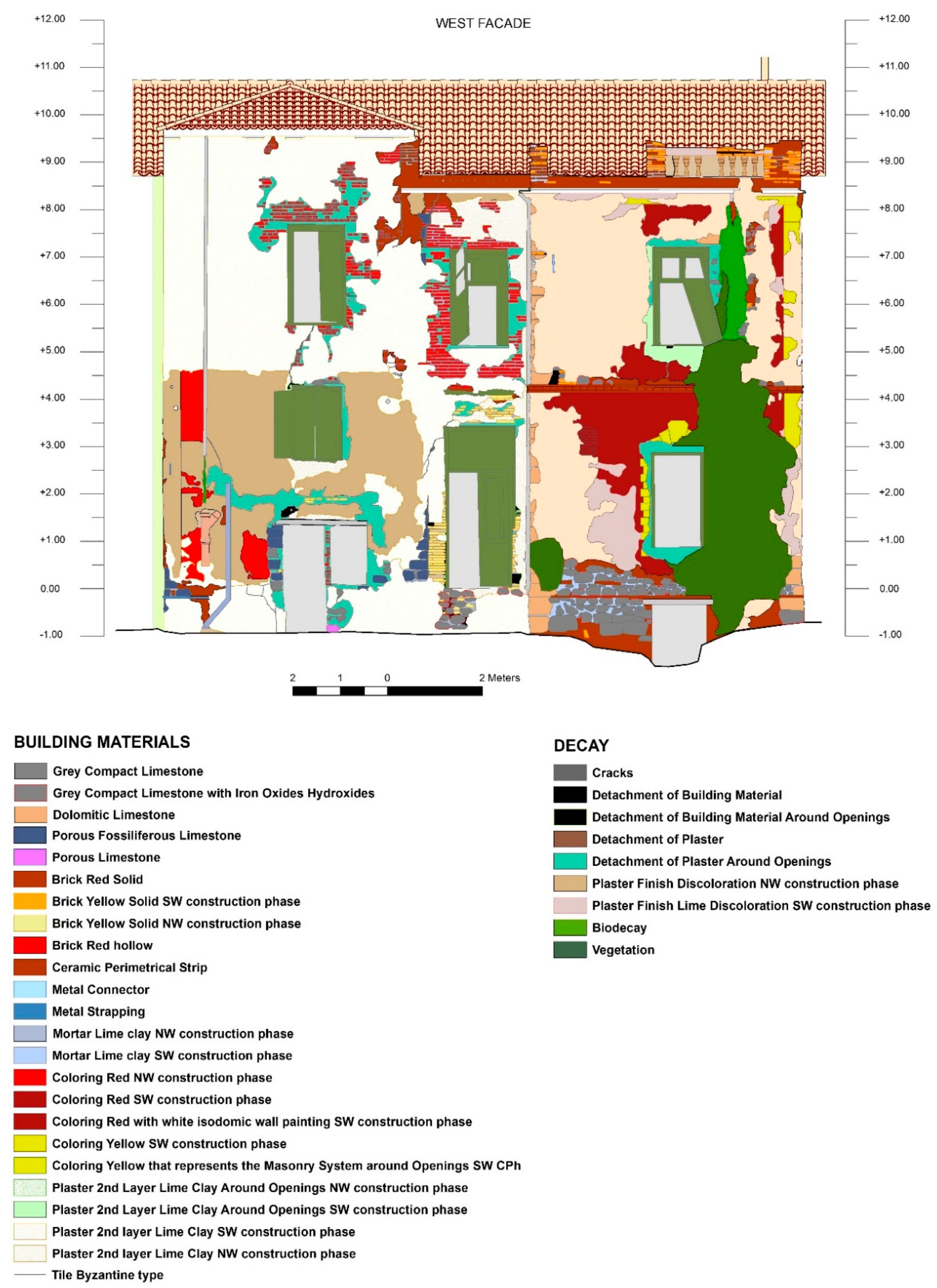
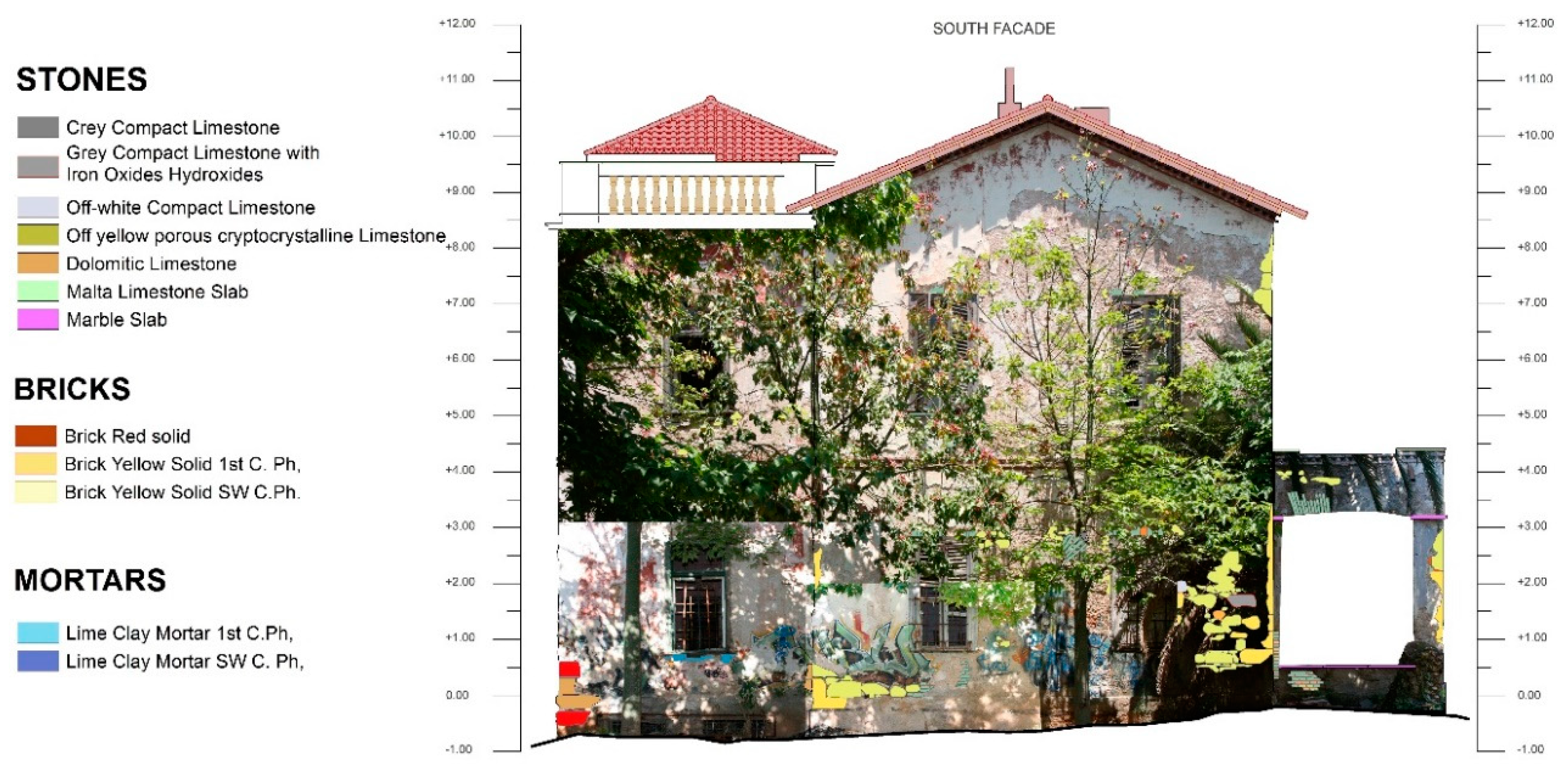
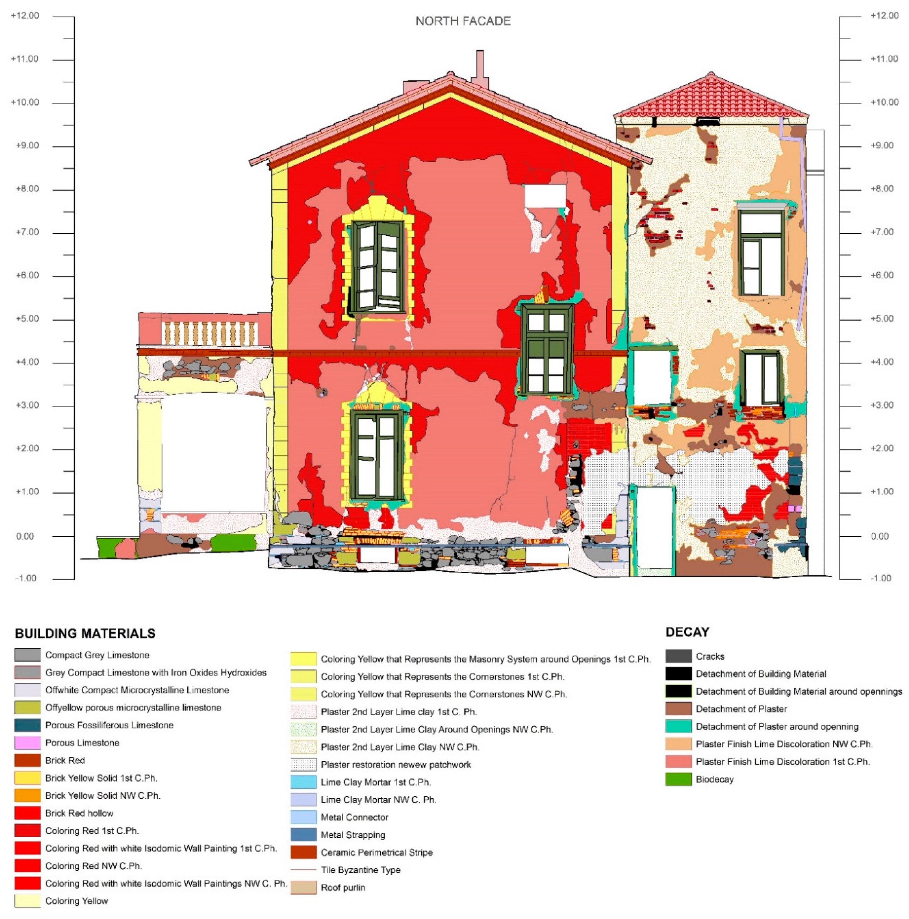
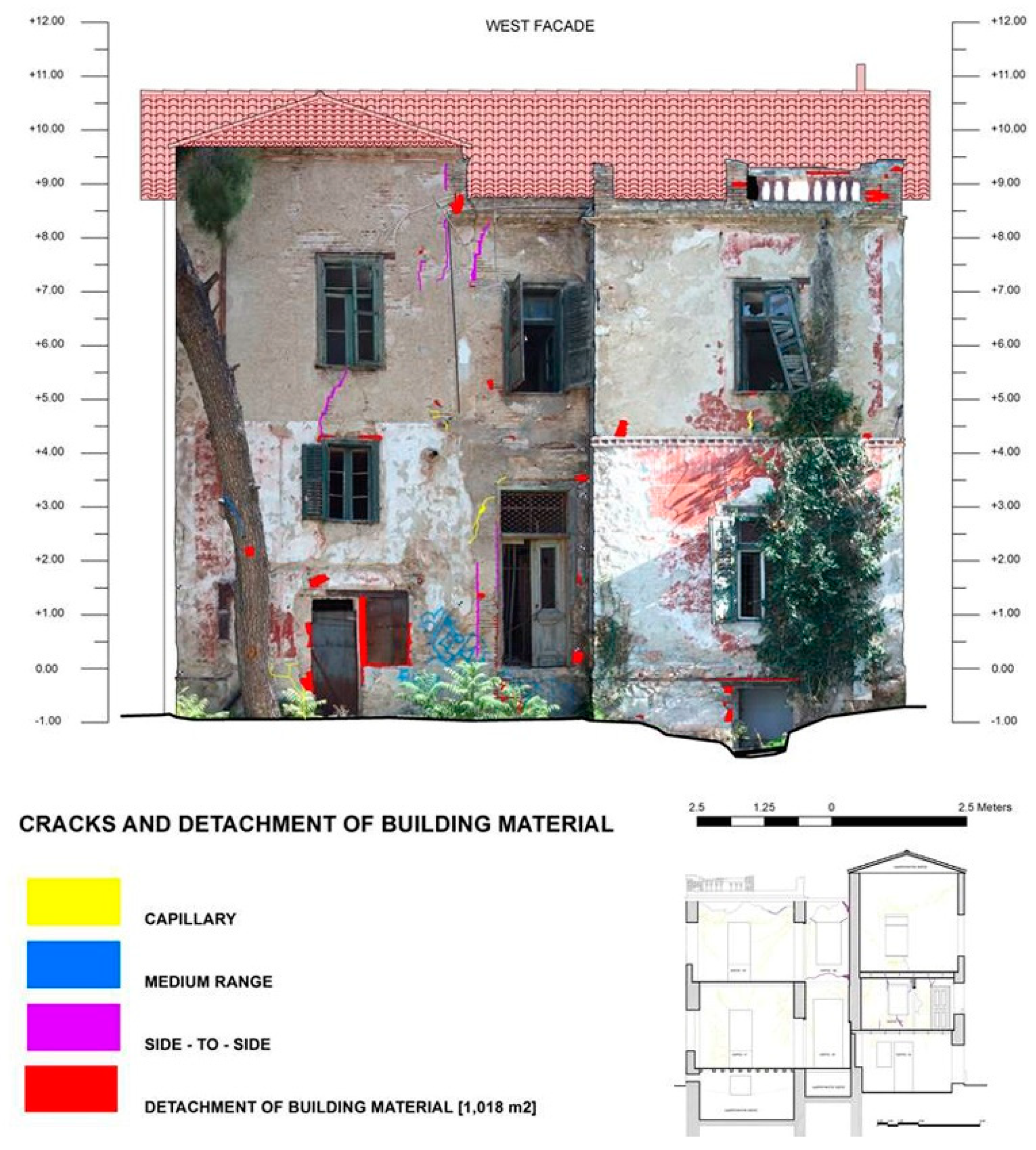
3.4. GIS Thematic Mapping
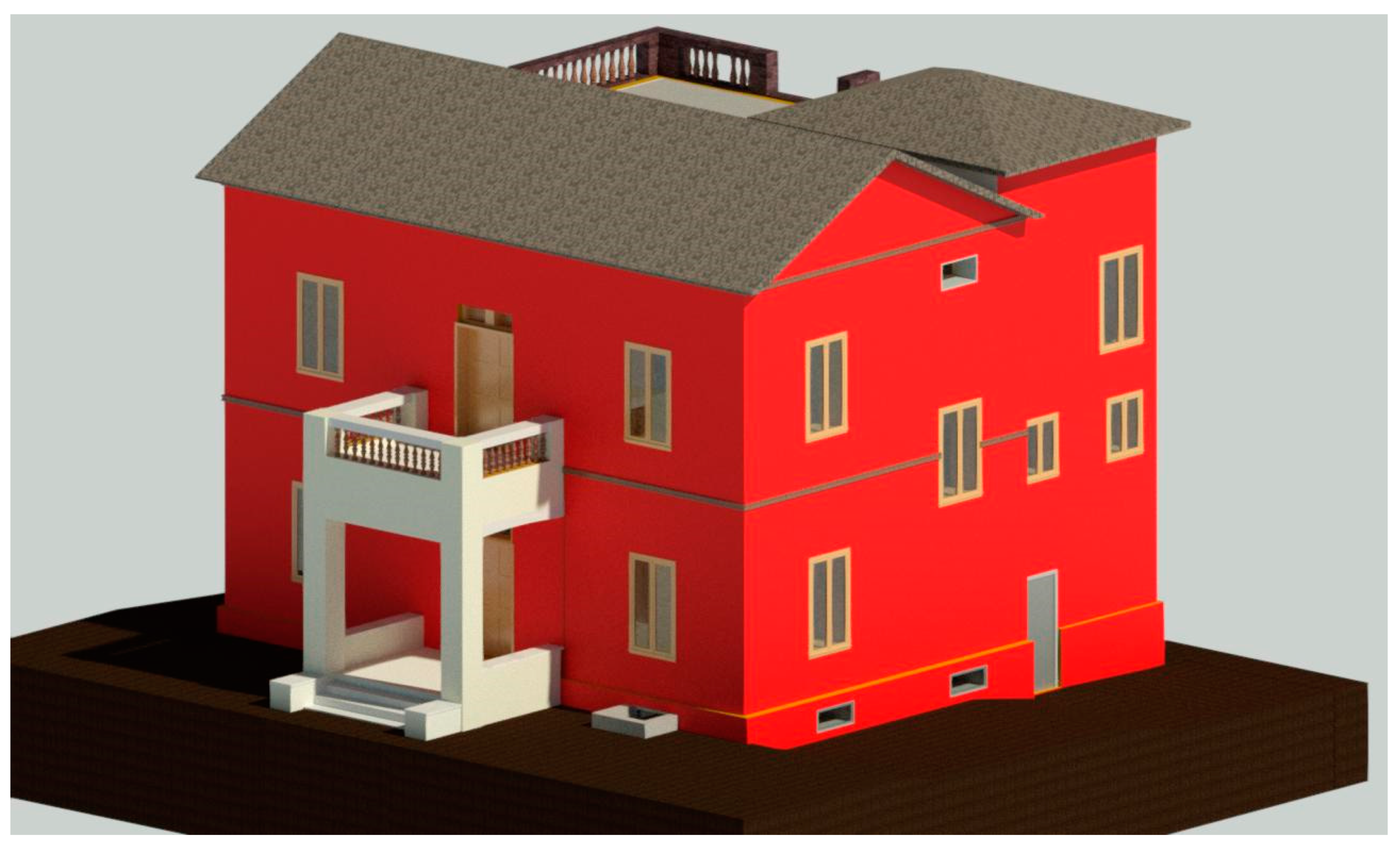
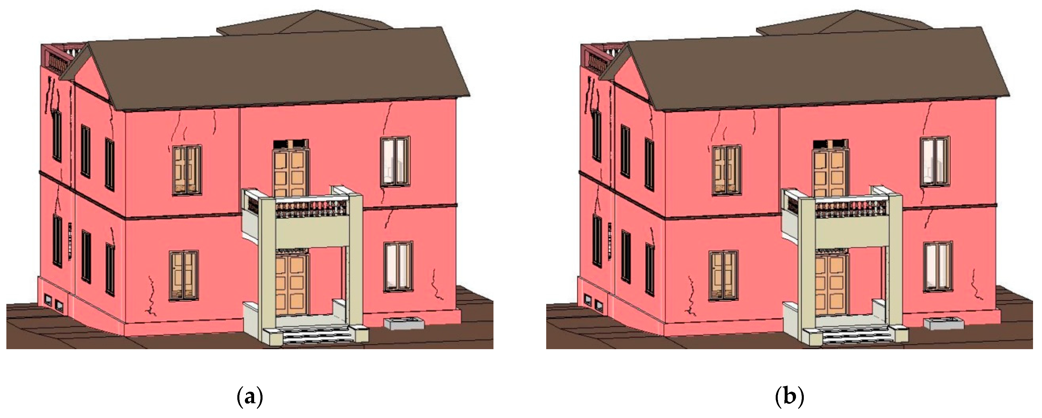
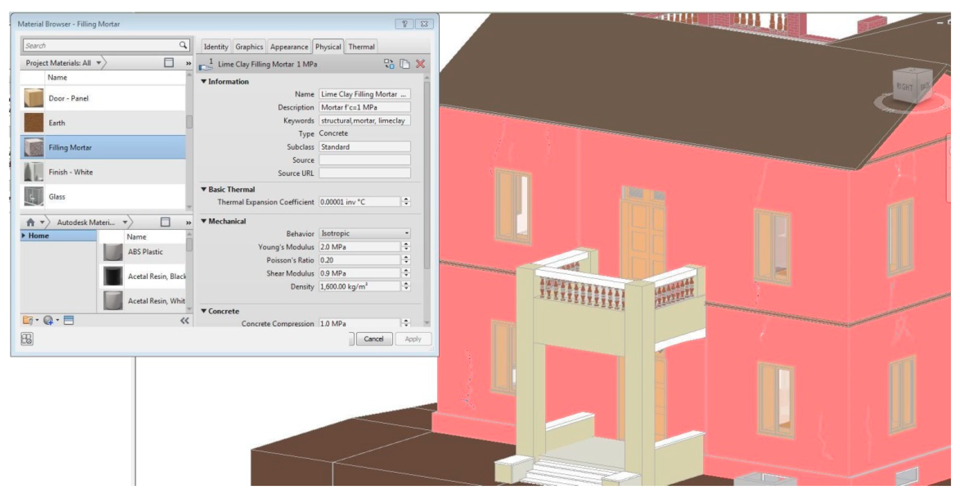
The integration of the collected multidisciplinary data was performed within a GIS environment. Spatial interrelation was acquired and geospatial attributes were developed thus accomplishing a connection between qualitative and quantitative data. The logical data structure of the GIS platform was developed in such a manner that all the level of information were included, incorporating information from general data down to specific data: building as a whole, façade, parts of the historic building, type of documentation data and spatial features, depicting the recording type of information. The classification of the multidisciplinary data (including building materials, decay, etc.) within the information system was performed via a CAD environment, through a detailed digitization, using orthophotos of each facade as blueprints, while all the qualitative and numeric information were imported in an attribute database. GIS operations are utilized for the documentation of the building materials, as well as for the modelling and analysis of the decay extent and patterns. Relational and Boolean operations were used as well as geoprocessing analysis for the development of thematic maps of the historic building. The thematic maps of the facades of the historic building demonstrate the variation of the building materials and the structural system which alters according to the construction phases, thus providing valuable information related to the masonries and their interconnection on a structural level (Figure 8, Figure 9, Figure 10 and Figure 11).
The thematic maps of the exterior facades, depicting the decay extent related to structural integrity were developed. In addition, the classification of the cracks feature was made, corresponding to three classes, based on the hazard range, capillary, medium range and side to side, while areas where detachment of building material was noticed, are also depicted (Figure 12, Figure 13, Figure 14 and Figure 15).
In Figure 12, the thematic map of the west façade demonstrates the severe deterioration of the walls, presenting cracks that reach the interior of the building and goes side-to-side, while capillary cracks are nearly absent. The area with the highest amount of cracking, is in fact one of the additions on the historic building and more specifically the third one, indicating a deterioration mechanism that affects the structure of the building as a whole. Given the fact that the cracks are located in the upper part of the façade, structural deformations, as well as possible moisture issues, emerge as possible decay factors which could interpret such degradation phenomena. Regarding the location of the cracks in the northwest upper part, information from the architectural drawings of the building, demonstrate that modifications were made and the restroom facilities were located in this area. Since the building was uninhabited for a very long time, plumbing system malfunctions could actively contribute to moisture accumulation and consequently to areas of remaining dampness. The cracks located near the interface of the 2nd and 3rd construction phase, can be attributed to incompatibility between the two structures and their building materials. Therefore, the extensive localization of the cracks, can be interpreted by such degradation parameters. In addition, the architectural section (Figure 12), demonstrates the extent of the side-to-side cracks that prevail in the third construction phase (northwest), further indicating its susceptibility to degradation phenomena.
In the north façade of the building (Figure 13), excessive amount of building material detachment is concentrated in the area where the third construction phase is located (northwest), while a side to side crack, located above the first floor window of the first construction phase, can be also noticed in the architectural drawing. In addition, detachment of building material located in the lower part of the façade, indicates phenomena of rising damp, nevertheless, severe cracking in the structure of the first construction phase is not noticed.
Regarding the thematic map of the east facade (Figure 14), which belongs to the first construction phase structure, various capillary cracks are present, the detachment of the exterior plaster (reaching the 1/3 of the total area of the façade) indicates humidity issues, however deformations and side-to side cracks, are nearly absent, apart from a crack located in the southeast first floor window, as indicated on the architectural section.
In the south façade, a side to side crack, corresponding to the interface of two of the structural phases (1st and 2nd) prevails, providing information regarding the incompatibility of the constructed elements in terms of building material and structural behavior, resulting in degradation phenomena and loads. In addition, various side to side cracks are present in the southwest part of the façade (2nd construction phase) (Figure 15).

3.5. HBIM Creation

A methodological framework that incorporates data deriving from the multidisciplinary documentation and providing information regarding the current state of preservation and the structural assessment of the masonry of the historic building may serve as a valuable tool which can assist in the creation of an HBIM. Through this process, the 3D data acquisition information is combined with the results from the building materials analysis in a 2D environment initially allowing the qualitative and quantitative information to be projected on a BIM that has derived from both architectural documentation data and the 3D point cloud from geometric documentation. Moreover, during the HBIM development, various types of information incorporating data regarding the state of preservation were utilized. Within the HBIM, each element obtained characteristics on both morphological and typological terms. Every element was enriched by the information that derived from the multidisciplinary documentation process such as its morphological features, the type of building materials, its geometric irregularities in conjunction with the standardized structural elements, its variation terms of susceptibility regarding the decay mechanisms that affect the structure, depending on the construction phase etc. In Figure 16, the stratigraphic information regarding the structural walls is presented.
The stratigraphic information of this structural element of a wall of the 1st construction phase, presented herein, includes information regarding its composition, type of building material, width of the construction wall and masonry’s layers. This information regarding the width and the masonry, derives from the in situ NDT results of the GPR prospection, while the building material selection from the in lab analytical testing. This process was applied for every element that was developed within the HBIM environment, resulting to a semantically enriched 3D HBIM of the historic building (Figure 17).

3.6. Integration of HBIM with GIS Results

The semantic enrichment of the HBIM of the historic building, addresses various use cases of heritage buildings in the Mediterranean region, incorporating information in relation to the categories of “wall components”, “stairs”, “windows”, “roofs” and “doors”. In the case of Villa Klonaridi, information deriving from the state of preservation study—including all the information regarding the building materials used, the types of construction walls, the historical documentation study and the structural analysis, are linked, semantically enriching the model. Moreover, the analysis of building materials’ information, as well as their distribution in GIS thematic maps, are enclosed within the HBIM in terms of semantic enrichment, creating an innovative approach towards building material and decay information analysis utilizing the tools provided by Revit. In Figure 18a,b, the integration of decay mapping in terms of cracks, and their classification type, as it has been developed through the GIS operation tools, within an HBIM environment, is demonstrated. In the updated HBIM, the cracks have been created, according to their classification type (capillary, medium size, side to side), including thus not only the qualitative enrichment but also the quantification of data regarding cracks, which affect the structural stability and response of the structure. Through this insight information, interventions regarding restoration works may be monitored, not only in a qualitative manner but also in terms of quantification of the restoration works and their durability and effectiveness, leading to the optimum results towards sustainable preservation and intervention works.
The elements of the cracks as a result of decay mechanisms were incorporated in the HBIM as voids. Information regarding geographical data as well as which wall element is cut, can be obtained. However, this type of information, embedded within a BIM system, can be altered and quantitative information can derive from such elements, only if the void is transformed in a solid element. Once the crack obtains a solid element character, building material type can be imported. Within this framework, restoration plans, described only in studies and reports and implemented only on-site, can be incorporated within the HBIM system, including information regarding the compatible restoration material, selected per structural construction phase, as well as the prevailing degradation mechanisms. In Figure 19, a lime clay filling mortar of 1MPa compressive strength is created (as a material type in HBIM), including all the morphological and physical-chemical characteristics, as the study indicates [49]; thus providing qualitative and quantitative information for the restoration process, ensuring compatible and performing restoration actions, as well as adequate documentation of restoration works.

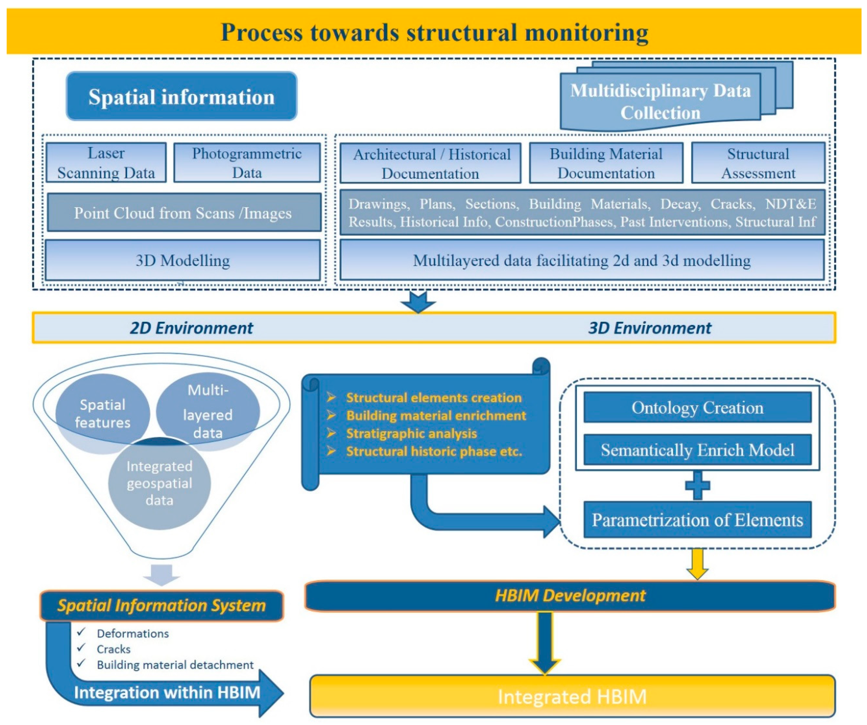
3.7. Process towards Integrated HBIM

A workflow towards the HBIM creation including the multidisciplinary geometrical and non-geometrical data is herewith presented in Figure 20. The process incorporates data deriving from multidisciplinary documentation and provides information related to the current state of preservation and structural assessment of the masonry of a historic building and could be considered as a useful tool for the creation of an integrated HBIM. Through this process, the 3D data acquisition information are combined with the results from the building material analysis, the structural information and construction phases along with the resulting geospatial features deriving from a GIS environment, resulting in an integrated HBIM, where qualitative and quantitative information are classified and projected, in terms of semantic enrichment.

4. Discussion

Through the 2D and 3D documentation of the decay patters concerning structural flaws and damages, within a GIS and BIM environment, qualitative and quantitative results were depicted and presented. Diagrams including information regarding the extent and the range of the cracks and detachment of building materials in relation with their location on the building were developed, additionally including information of the environmental parameters and the construction phases.
More specifically, the decay factors that prevail in the structure of the building in terms of cracks and loss of building material are presented through a diagram (Figure 21) deriving from the 2D GIS analysis. A high percentage in the length of the cracks was observed, mainly in the west and south façade with 62% and 72% side to side cracks respectively, thus assisting in the conclusion that the additional expansions of the historic building were of lower quality structure compared to the first construction phase. In addition, the capillary cracks prevail in the east façade, causing only superficial decay, indicating the cohesive structure of the first construction phase.
When assessing cracks, the width of the crack is often more important than the length of the crack. In Figure 22, a slight alteration is observed in terms of quantifying the area that each crack holds, indicating that the width of the side to side cracks are larger than their length, thus providing additional qualitative information regarding the structure’s state of preservation. Although the higher percent of decay in terms of cracks’ length is observed in the south façade, the percentage grows even higher when the area of the cracks is computed. In addition, the cracks are concentrated on the structure of the southwest construction phase, with the eminent side to side crack to divide the different masonries of the south, in the two construction phases. This implies that although the masonry of the 2nd construction phase has similarities with the initial structure, there is no interlocking between the masonries.
In the west façade, where the latter construction phases of the building are encountered, there is a large percentage of side to side cracking, concentrated in the masonry of the 3rd construction phase. This can be justified by the masonry-type, which is a limestone, mortar structure in the southwest of the wall (2nd C. Ph.), while brick-walls prevail in the upper part of the northwest (3rd C. Ph.). This decay pattern is also supported by the building material analysis, where the bricks of the 3rd construction phase presented micro-fractures and cracks and the building materials as a whole where of lower quality, compared to the building materials of 1st and 2nd construction phase.
Moreover, quantitative information regarding the extent of the cracks, in a 3D environment, including volumetric information, can be acquired. Quantification of the cracks within the HBIM environment was accomplished by converting the 2D data features in 3D volumetric elements. Processing of these data, results in valuable information regarding the preservation state of the structure, since the computation of the percentage of cracking in each wall can be acquired, thus providing information for refurbishment works. In Figure 23, the volumetric representation of the cracks indicates the need for immediate actions in order to achieve an adequate level of structural integrity, especially in the south and west sides of the historic building. In addition, conservation interventions can be quantified, in terms of required restoration filling material and is demonstrated through a volumetric diagram (Figure 24), facilitating the necessary restoration actions and also cost estimation.
Overall, in this study, a representative diagram illustrates the fields of information required to facilitate monitoring of a structure (Figure 25). Integration between information platforms of GIS and BIM in the case of cultural heritage assets preservation is therefore presented. Aspects and results, deriving from a 2D representation of the current state of preservation can be validated. Through the thematic mapping in a 2DGIS environment, information regarding spatial distribution of decay, such as rising damp detachments of building materials, as well as cracks and deformations, are depicted, mapped, analyzed and future restoration interventions can be planned more effectively. Moreover, the side-to-side cracks, mostly located in the interface of the different construction phases, are projected in the HBIM and are compiled as elements, enriching the model. This process provides valuable information regarding refurbishment actions incorporating within the HBIM the types of restoration filling materials that should be applied. Since, interoperability is a main advantage in a HBIM environment, designers, engineers and architects can continuously contribute data during rehabilitation works, aiming to better organize possible required readjustments and apply on time corrective actions.

5. Conclusions

Within this study, ICT environments, and more specifically GIS and BIM, were utilized as integrated digital environments aiming towards the structural assessment of a historic building. Qualitative and quantitative information derived from the elaboration of multidisciplinary results, provided information regarding the current state of preservation, thus assisting the decision making towards the selection of the necessary restoration materials and intervention works.
Furthermore, data deriving from a spatial information system were incorporated within an HBIM. This integration provided crucial information regarding the structural assessment of the building, through the 2D to 3D process, thus introducing the interoperability of these two information systems. Nevertheless, the adaptation of the 2D vector layers (GIS environment) within a BIM is not illustrated herein, since major compatibility issues regarding ontologies still exist. Further research in this scientific field may provide the integration of these two information systems.
In addition, the integration between laser scanning and photogrammetric products leads to a 3D model of a historic building and/or 3D textured point cloud that can, then, be converted into a BIM environment. The presented process provides valuable information regarding the creation of a HBIM including elaborated nondestructive testing results in the element creation process. Although in the past few years there has been an immerse interest towards HBIM creation, there is still a lot of research to be conducted by incorporating building material information, not just as an input when forming an element, but as a feature enclosing all the relative information. Furthermore, implementation and integration within a FEM of the HBIM, could facilitate towards a comprehensive and concise model where multidisciplinary study results can be embedded and correlated with the structural assessment of the building, thus leading to the optimum restoration works and assuring its health monitoring through time.
Moreover, BIM software presents the capability of integrating metadata via a database or spreadsheets in BIM environment, thus achieving the inclusion of other multidisciplinary information. The main step towards ensuring sustainability of a cultural heritage asset is the inclusion of other parameters as well, encapsulating not only degradation patterns and building materials, but also, the impact of environmental loads, such as variations in temperature and humidity.
The proposed methodology applied on the case study of Villa Klonaridi demonstrates that within an information system, decay phenomena can be mapped, classified and assessed, employing information regarding the structure’s history. It is demonstrated that the incorporation of multidisciplinary data of a cultural heritage asset, within GIS and HBIM systems, support diagnosis of actual and real causes of degradation, by employing information from their database systems, which contain all the qualitative and quantitative information in a 2D and 3D environment respectively. The representation of the geometry and the different construction phases of a historic building, offers a holistic approach, advancing from a fragmented knowledge based system into an established multilateral and multidisciplinary information system, where monitoring of a historic building can be accomplished and future restoration works can be applied, minimizing the threats and risks of the past.
Further research is necessary, especially regarding the connection and link between HBIM systems, databases and further integration of non-destructive techniques results, which can offer updated information regarding the preservation state of a building as well as its structural integrity. The usability of these systems for obtaining a historic buildings’ pathology is considered a necessity and at the same time can assist towards the development of a methodological framework enclosing all the aspects of interest in the field of monument protection. Through automated processes, pattern recognition may alter the documentation process, within a semantic approach, by modelling the structural elements and decay patterns using image-based 3D models and meshes, enhancing the HBIM development. Finally, depending on the level of detail of an HBIM and taking into account the demands and purpose it serves, additional tools should be tested and used, in order to optimize cost and time efficiency.

Author Contributions

E.T., E.T.D. and A.M. conceived the research; A.M. supervised the overall writing of the paper; I.A.N. performed the GIS information system development for his master thesis entitled “The contribution of Geometric Documentation and management methods in the integrated diagnostic study of the historic building of Villa Klonaridi” under the supervision of A.M. and C.I.; C.I. and E.T. analyzed the surveying data, designed the image-based experimental data gathering, performed the data gathering, management, elaboration and integration; E.T., E.T.D. and I.A.N. performed the analysis of the thematic map development; E.T. performed the BIM system development and the analysis of the BIM decay mapping development; E.T., E.T.D. and A.M. conceived and designed the methodology of the study; E.T. and E.T.D. wrote the paper; C.I. did the final editing. Credits for the figures that are not adopted by other reference follow the present manuscript. All authors have read and agreed to the published version of the manuscript.

Funding

This research was funded by the research program INCEPTION (Inclusive Cultural Heritage in Europe through 3D semantic Modelling), funded by the European Union’s Horizon 2020 research and innovation program under grant agreement No. 665220.

Conflicts of Interest

The authors declare no conflicts of interest.

References

  1. Diara, F.; Rinaudo, F. Open Source HBIM for Cultural Heritage: A Project Proposal. ISPRS Int. Arch. Photogramm. Remote Sens. Spat. Inf. Sci. 2018, XLII–2, 303–309. [Google Scholar] [CrossRef] [Green Version]
  2. Banfi, F.; Previtali, M.; Stanga, C.; Brumana, R. A Layered-Web Interface based on HBIM and 360deg; Panoramas for Historical, Material and Geometric Analysis. ISPRS Int. Arch. Photogramm. Remote Sens. Spat. Inf. Sci. 2019, XLII-2/W9, 73–80. [Google Scholar] [CrossRef] [Green Version]
  3. Asteris, P.G.; Moropoulou, A.; Skentou, A.D.; Apostolopoulou, M.; Mohebkhah, A.; Cavaleri, L.; Rodrigues, H.; Varum, H. Stochastic vulnerability assessment of masonry structures: Concepts, modeling and restoration Aspects. Appl. Sci. 2019, 9, 243. [Google Scholar] [CrossRef] [Green Version]
  4. Barbieri, G.; Biolzi, L.; Bocciarelli, M.; Fregonese, L.; Frigeri, A. Assessing the Seismic Vulnerability of a Historical Building. Eng. Struct. 2013, 57, 523–535. [Google Scholar] [CrossRef]
  5. Bitelli, G.; Balletti, C.; Brumana, R.; Barazzetti, L.; Previtali, M.; D’Urso, G.; Rinaudo, F.; Tucci, G. Metric Documentation of Cultural Heritage: Research directions from the Italian GAMHER Project. ISPRS Int. Arch. Photogramm. Remote Sens. Spat. Inf. Sci. 2017, XLII-2/W5, 83–90. [Google Scholar] [CrossRef] [Green Version]
  6. Asteris, P.G.; Plevris, V. Handbook of Research on Seismic Assessment and Rehabilitation of Historic Structures; IGI Global: Hershey, PA, USA, 2015; pp. 1–867. [Google Scholar]
  7. Chiabrando, F.; Di Lolli, A.; Patrucco, G.; Spanò, A.; Sammartano, G.; Teppati Losè, L. Multitemporal 3D Modelling for Cultural Heritage emergency during Seismic events: Damage assessment of S. Agostino church in Amatrice (RI). ISPRS Int. Arch. Photogramm. Remote Sens. Spat. Inf. Sci. 2017, XLII–5/W1, 69–76. [Google Scholar] [CrossRef] [Green Version]
  8. Asteris, P.G.; Douvika, M.G.; Apostolopoulou, M.; Moropoulou, A. Seismic and Restoration Assessment of Monumental Masonry Structures. Materials 2017, 10, 895. [Google Scholar] [CrossRef] [Green Version]
  9. Fregonese, L.; Barbieri, G.; Biolzi, L.; Bocciarelli, M.; Frigeri, A.; Taffurelli, L. Surveying and Monitoring for Vulnerability Assessment of an Ancient Building. Sensors 2013, 13, 9747–9773. [Google Scholar] [CrossRef]
  10. Georgopoulos, A. Data Acquisition for the Geometric Documentation of Cultural Heritage. In Mixed Reality and Gamification for Cultural Heritage; Ioannides, M., Magnenat-Thalmann, N., Papagiannakis, G., Eds.; Springer International Publishing: Cham, Switzerland, 2017; Volume 2, pp. 29–73. [Google Scholar] [CrossRef]
  11. Ioannidis, C.; Georgopoulos, A. Innovative Techniques for the Acquisition and Processing of Multisource Data for the Geometric Documentation of Monuments. Int. J. Arch. Comp. 2007, 5, 179–198. [Google Scholar] [CrossRef]
  12. Letellier, R.; Schmid, W.; LeBlanc, F. Guiding Principles Recording, Documentation, and Information Management for the Conservation of Heritage Places; J. Paul Getty Trust, Getty Conservation Institute: Los Angeles, USA, 2007; pp. 36–38. [Google Scholar]
  13. Salonia, P.; Negri, A. Historical buildings and their decay: Data recording, analyzing and transferring in an ITC environment.). ISPRS Int. Arch. Photogramm. Remote Sens. Spat. Inf. Sci. 2003, XXXIV–5/W12, 302–306. [Google Scholar]
  14. Meroño, J.E.; Perea, A.J.; Aguilera, M.J.; Laguna, A.M. Recognition of materials and damage on historical buildings using digital image classification. S. Afr. J. Sci. 2015, 111, 1–9. [Google Scholar] [CrossRef] [Green Version]
  15. Guidi, G.; Remondino, F. 3D modeling from real data. In Modeling and Simulation in Engineering; Alexandru, C., Ed.; InTech Publisher: Rijeka, Croatia, 2012; pp. 69–102. ISBN 978-953-51-0012-6. [Google Scholar] [CrossRef] [Green Version]
  16. Kersten, T.P.; Lindstaedt, M. Image-based low-cost systems for automatic 3D recording and modelling of archaeological finds and objects. In EuroMed 2012: Progress in Cultural Heritage Preservation; Ioannides, M., Fritsch, D., Leissner, J., Davies, R., Remondino, F., Caffo, R., Eds.; LNCS; Springer: Berlin/Heidelberg, Germany, 2012; Volume 7616, pp. 1–10. [Google Scholar] [CrossRef]
  17. Remondino, F. Photogrammetry—Basic Theory. In 3D Recording and Modelling in Archaeology and Cultural Heritage—Theory and Best Practices; Remondino, F., Campana, S., Eds.; Archaeopress BAR Publication Series 2598; Gordon House: Oxford, UK, 2014; pp. 63–72. ISBN 9781407312309. [Google Scholar]
  18. Moropoulou, A.; Delegou, E.T.; Avdelidis, N.P.; Athanasiadou, A. Integrated diagnostics using advanced in situ measuring technology. In Proceedings of the 10th International Conference on Durability of Building Materials and Components, Lyon, France, 17–20 April 2005; pp. 1116–1123. [Google Scholar]
  19. Moropoulou, A.; Labropoulos, K.C.; Delegou, E.T.; Karoglou, M.; Bakolas, A. Non-Destructive Techniques as a tool for the protection of Built Cultural Heritage. Constr. Build. Mater. 2013, 48, 1222–1239. [Google Scholar] [CrossRef]
  20. Adamopoulos, E.; Tsilimantou, E.; Keramidas, V.; Apostolopoulou, M.; Karoglou, M.; Tapinaki, S.; Ioannidis, C.; Georgopoulos, A.; Moropoulou, A. Multi-Sensor Documentation of metric and qualitative information of Historic Stone structures. ISPRS Int. Arch. Photogramm. Remote Sens. Spat. Inf. Sci. 2017, IV-2/W2, 1–8. [Google Scholar] [CrossRef] [Green Version]
  21. Delegou, E.T.; Tsilimantou, E.; Oikonomopoulou, E.; Sayas, J.; Ioannidis, C.; Moropoulou, A. Mapping of building materials and consevation interventions using GIS: The case of Sarantapicho Acropolis and Erimokastro Acropolis in Rhodes. Int. J. Herit. Digit. Era 2013, 2, 631–653. [Google Scholar] [CrossRef]
  22. Günay, S. Geographical Information Systems as a tool for 3D visualization of lost Architectural Heritage. ISPRS Int. Arch. Photogramm. Remote Sens. Spat. Inf. Sci. 2019, IV-2/W6, 69–75. [Google Scholar] [CrossRef] [Green Version]
  23. Del Curto, D.; Garzulino, A.; Allegretti, F.; Mazza, S. GIS or BIM? A comparison applied to the conservation management plan of a 20th century architectural Heritage. ISPRS Int. Arch. Photogramm. Remote Sens. Spat. Inf. Sci. 2019, XLII-2/W15, 365–372. [Google Scholar] [CrossRef] [Green Version]
  24. Saygi, G.; Agugiaro, G.; Hamamcıoğlu-Turan, M.; Remondino, F. Evaluation of GIS and BIM roles for the Information Management of Historical Buildings. ISPRS Int. Arch. Photogramm. Remote Sens. Spat. Inf. Sci. 2013, II-5/W1, 283–288. [Google Scholar] [CrossRef] [Green Version]
  25. Baik, A.; Yaagoubi, R.; Boehm, J. Integration of Jeddah Historical BIM and 3D GIS for Documentation and Restoration of Historical Monument. ISPRS Int. Arch. Photogramm. Remote Sens. Spat. Inf. Sci. 2015, XL-5/W7, 29–34. [Google Scholar] [CrossRef] [Green Version]
  26. Dore, C.; Murphy, M. Integration of Historic Building Information Modeling (HBIM) and 3D GIS for Recording and Managing Cultural Heritage Sites. In Proceedings of the 2012 18th International Conference on Virtual Systems and Multimedia, Milan, Italy, 2–5 September 2012; pp. 369–376. [Google Scholar] [CrossRef] [Green Version]
  27. Logothetis, S.; Delinasiou, A.; Stylianidis, E. Building Information Modelling for cultural heritage: A review. ISPRS Int. Arch. Photogramm. Remote Sens. Spat. Inf. Sci. 2015, II-5/W3, 177–183. [Google Scholar] [CrossRef] [Green Version]
  28. Volk, R.; Stengel, J.; Schultmann, F. Building Information Modelling (BIM) for existing buildings—Literature review and future needs. J. Autom. Constr. 2014, 38, 109–127. [Google Scholar] [CrossRef] [Green Version]
  29. De Luca, L.; Véron, P.; Florenzano, M. A generic formalism for the semantic modeling and representation of architectural elements. Vis. Comput. 2007, 23, 181–205. [Google Scholar] [CrossRef] [Green Version]
  30. Maxwell, I. Integrating Digital Technologies in support of historic Building Information Modelling: Bim4conservation (HBIM); A COTAC BIM4Conservation (HBIM) Report; The Building Crafts College: London, UK, 2014; pp. 1–50. [Google Scholar]
  31. Quattrini, R.; Malinverni, E.S.; Clini, P.; Nespeca, R.; Orlietti, E. From TLS to HBIM. High quality semantically—Aware 3D modeling of complex architecture. ISPRS Int. Arch. Photogramm. Remote Sens. Spat. Inf. Sci. 2015, XL-5/W4, 367–374. [Google Scholar] [CrossRef] [Green Version]
  32. Bianchini, C.; Nicastro, S. The definition of the Level of Reliability: A contribution to the transparency of Historical-BIM processes. Dienne 2018, 2, 46–60. [Google Scholar]
  33. Attenni, M.; Bianchini, C.; Ippolito, A. HBIM: An information model for historical building. In Reflections: The art of drawing/ the drawing of art. In Proceedings of the 41° Convegno UID, Perugia, Italy, 19–21 September 2019; pp. 285–296. [Google Scholar]
  34. Albano, R. Investigation on Roof Segmentation for 3D Building Reconstruction from Aerial LIDAR Point Clouds. Appl. Sci. 2019, 9, 4674. [Google Scholar] [CrossRef] [Green Version]
  35. Macher, H.; Landes, T.; Grussenmeyer, P. From Point Clouds to Building Information Models: 3D Semi-Automatic Reconstruction of Indoors of Existing Buildings. Appl. Sci. 2017, 7, 1030. [Google Scholar] [CrossRef] [Green Version]
  36. Garagnani, S.; Manferdini, A.M. Parametric accuracy: Building information modeling process applied to the cultural heritage preservation. ISPRS Int. Arch. Photogramm. Remote Sens. Spat. Inf. Sci 2013, XL-5/W1, 87–92. [Google Scholar] [CrossRef] [Green Version]
  37. Brumana, R.; Oreni, D.; Raimondi, A.; Georgopoulos, A.; Bregianni, A. From survey to HBIM for documentation, dissemination and management of built heritage: The case study of St. In Maria in Scaria d’Intelvi. In Proceedings of the Digital Heritage 2013—Federating the 19th Int’l VSMM, 10th Eurographics GCH, and 2nd UNESCO Memory of the World Conferences, Plus Special Sessions from CAA, Marseille, France, 28 October–1 November 2013; pp. 497–504. [Google Scholar]
  38. Utica, G.; Pinti, V.; Guzzoni, L.; Bonelli, S.; Brizzolari, A. Integrating Laser Scanner and BIM for conservation and reuse: ‘the Lyric Theatre of Milan’. ISPRS Int. Arch. Photogramm. Remote Sens. Spat. Inf. Sci. 2017, IV-5/W1, 77–82. [Google Scholar] [CrossRef] [Green Version]
  39. Chiabrando, F.; Turco, M.L.; Rinaudo, F. Modeling the decay in an HBIM starting from 3D point clouds. A followed approach for Cultural Heritage Knowledge. ISPRS Int. Arch. Photogramm. Remote Sens. Spat. Inf. Sci. 2017, XLII-2/W5, 605–612. [Google Scholar] [CrossRef] [Green Version]
  40. Oreni, D.; Brumana, R.; Della Torre, S.; Banfi, F.; Previtali, M. Survey turned into HBIM: The restoration and the work involved concerning the Basilica di Collemaggio after the earthquake (L’Aquila). ISPRS Int. Arch. Photogramm. Remote Sens. Spat. Inf. Sci. 2014, II-5, 267–273. [Google Scholar] [CrossRef] [Green Version]
  41. Osello, A.; Rinaudo, F. Cultural heritage management tools: The role of GIS and BIM. In 3D Recording, Documentation and Management in Cultural Heritage; Stylianidis, E., Remondino, F., Eds.; Whittles Publishing: Dunbeath, UK, 2016; pp. 105–124. [Google Scholar]
  42. Bruno, N.; Roncella, R. HBIM for Conservation: A New Proposal for Information Modeling. Remote Sens. 2019, 11, 1751. [Google Scholar] [CrossRef] [Green Version]
  43. Tsilimantou, E.; Delegou, T.E.; Ioannidis, C.; Moropoulou, A. Geoinformation techniques for the 3D visualisation of historic buildings and representation of a building’s pathology. In Proceedings of the SPIE 9688, Fourth International Conference on Remote Sensing and Geoinformation of the Environment (RSCy2016), Paphos, Cyprus, 12 August 2016; p. 968810. [Google Scholar] [CrossRef]
  44. Danihl, M. The Restoration of the Klonaridis Villa; Library of Technical Chamber of Greece, Archives: Athens, Greece, 2012; Available online: http://library.tee.gr/digital/m2616/m2616_daniil.pdf (accessed on 11 April 2019).
  45. Tsilimantou, E.; Delegou, E.T.; Labropoulos, K.; Karoglou, M.; Bourbos, E.; Moropoulou, A. Multisensor Fusion of NDTs with Geometric Documentation for the Assessment of Historic Buildings Preservation State. In Proceedings of the International Symposium on Structural Health Monitoring and Nondestructive Testing, Saarbrücken, Germany, 4–5 October 2018; p. 8. [Google Scholar]
  46. Žarnić, R.; Rajčić, V.; Skordaki, N. A Contribution to the Built Heritage Environmental Impact Assessment. ISPRS Int. Arch. Photogramm. Remote Sens. Spat. Inf. Sci. 2015, II-5/W3, 389–394. [Google Scholar] [CrossRef] [Green Version]
  47. Kioussi, A.; Karoglou, M.; Labropoulos, K.; Bakolas, A.; Moropoulou, A. Integrated Documentation Protocols Enabling Decision Making in Cultural Heritage Protection. J. Cult. Her. 2013, 14, 141–146. [Google Scholar] [CrossRef]
  48. Di Giulio, R.; Maietti, F.; Piaia, E.; Medici, M.; Ferrari, F.; Turillazzi, B. Integrated Data Capturing requirements for 3D Semantic Modelling of Cultural Heritage: The INCEPTION protocol. ISPRS Int. Arch. Photogramm. Remote Sens. Spat. Inf. Sci. 2017, XLII-2/W3, 251–257. [Google Scholar] [CrossRef] [Green Version]
  49. Tsilimantou, E.; Nikitakos, I.A.; Delegou, E.T.; Soile, S.; Tapinaki, S.; Ioannidis, C.; Moropoulou, A. GIS modelling for integrated documentation of the historic building of Villa Klonaridi in Athens. In Proceedings of the 6th International Congress on Science and Technology for the Safeguard of Cultural Heritage in the Mediterranean Basin, Athens, Greece, 22–25 October 2013; Volume I, pp. 217–223. [Google Scholar]
Figure 1. Villa Klonaridi historic building.
Applsci 10 01078 g001
Figure 2. (a) Plan of the construction phases of the historic building; (b) east façade of Villa Klonaridi indicating the pathology of the walls.
Applsci 10 01078 g002
Figure 3. 3D model of Villa Klonaridi: (a) 3d mesh; (b) 3d textured model (northeast orientation).
Applsci 10 01078 g003
Figure 4. Infrared thermography (IRT) images of the north façade: (a) areas consisted of brick (below the window opening and the relieving arch above the basement window), present higher temperatures in comparison to plastered and un-plastered parts of the ruble-stone masonry; (b) the masonry area below the metal strapping, (applied for structural stability), presents lower temperatures in comparison to the masonry area above the metal strapping, indicating issues of rising damp at the lower parts of the north façade.
Applsci 10 01078 g004
Figure 5. IRT images of the north façade: (a) moisture issues are observed in the lower part of the 3rd construction phase structure; (b) temperature variations and different thermal conductivity behavior is observed between the building materials of the first and the third construction phase.
Applsci 10 01078 g005
Figure 6. Digital microscopy images of stones, bricks and mortars from the three construction phases: first construction phase: (a) compact grey limestone with a ferrous vein evident; (b) red brick; (c) clay mortar with lumps of lime; second construction phase: (d) compact grey limestone with iron oxides and hydroxides; (e) yellow Brick; (f) lime-clay mortar; third construction phase: (g) compact grey limestone; (h) light-yellow brick with micro-fissuring; (i) lime-clay mortar with micro-fissuring and low cohesion.
Applsci 10 01078 g006
Figure 7. Ground penetrating radar (GPR) measurement results indicating the masonry’s stratigraphy along with the 3D point cloud of the masonry under examination.
Applsci 10 01078 g007
Figure 8. Thematic map of building materials and decay of the east façade.
Applsci 10 01078 g008
Figure 9. Thematic map of building materials and decay of the west façade.
Applsci 10 01078 g009
Figure 10. Thematic map of building materials of the south façade.
Applsci 10 01078 g010
Figure 11. Thematic map of building materials and decay of the north façade.
Applsci 10 01078 g011
Figure 12. Thematic map of cracks and detachment of building materials depicted on the west façade of the building.
Applsci 10 01078 g012
Figure 13. Thematic map of cracks and detachment of building materials depicted on the north façade of the building.
Applsci 10 01078 g013
Figure 14. Thematic map of cracks and detachment of building materials depicted on the east façade of the building.
Applsci 10 01078 g014
Figure 15. Thematic map of cracks and detachment of building materials depicted on the south façade of the building.
Applsci 10 01078 g015
Figure 16. Wall structural element of the 1st construction phase incorporating stratigraphic information.
Applsci 10 01078 g016
Figure 17. HBIM of the historic building of Villa Klonaridi.
Applsci 10 01078 g017
Figure 18. Elements of cracks (all types) embedded within the HBIM of the building: (a) southeast of the historic building; (b) southwest of the historic building.
Applsci 10 01078 g018
Figure 19. Selection of lime-clay filling mortar in the structural element.
Applsci 10 01078 g019
Figure 20. Workflow indicating the proposed process towards HBIM creation and integration.
Applsci 10 01078 g020
Figure 21. Diagram illustrating the percentage of the length of each type of crack (m) for all facades of the building.
Applsci 10 01078 g021
Figure 22. Diagram illustrating the percentage of the area (m2) each type of crack possesses for all facades of the building.
Applsci 10 01078 g022
Figure 23. Comparative diagrams indicating the percentage of each façade of the building in regards to each type of crack.
Applsci 10 01078 g023
Figure 24. Volumetric diagram of the restoration filling material quantity in m3 for each crack category.
Applsci 10 01078 g024
Figure 25. Diagram demonstrating the monitoring of a structure by incorporating multidisciplinary data in an ICT environment, as well as the multidisciplinary results that can derive from the implementation of the proposed methodology.
Applsci 10 01078 g025

