Potential Reduction of Peripheral Local SAR for a Birdcage Body Coil at 3 Tesla Using a Magnetic Shield
 C.C. van Leeuwen1*
  B.R. Steensma1
  S.B. Glybovski2 M.F.J. Lunenburg3 C. Simovski4 D.W.J. Klomp1 C.A.T. van den Berg1 A.J.E. Raaijmakers1,5
- 1Department of Radiology, University Medical Center Utrecht, Utrecht, Netherlands
- 2Faculty of Physics and Engineering, ITMO University, St. Petersburg, Russia
- 3Tesla Dynamic Coils, Zaltbommel, Netherlands
- 4Department of Electronics and Nanoengineering, Aalto University, Espoo, Finland
- 5Biomedical Engineering Department, Eindhoven University of Technology, Eindhoven, Netherlands
The birdcage body coil, the standard transmit coil in clinical MRI systems, is typically a shielded coil. The shield avoids interaction with other system components, but Eddy Currents induced in the shield have an opposite direction with respect to the currents in the birdcage coil. Therefore, the fields are partly counteracted by the Eddy currents, and large coil currents are required to reach the desired B1+ level in the subject. These large currents can create SAR hotspots in body regions close to the coil. Complex periodic structures known as metamaterials enable the realization of a magnetic shield with magnetic rather than electric conductivity. A magnetic shield will have Eddy currents in the same direction as the coil currents. It will allow generating the same B1+ with lower current amplitude, which is expected to reduce SAR hotspots and improve homogeneity. This work explores the feasibility of a birdcage body coil at 3 T with a magnetic shield. Initially, we investigate the feasibility by designing a scale model of a birdcage coil with an anisotropic implementation of a magnetic shield at 7 T using flattened split ring resonators. It is shown that the magnetic shield destroys the desired resonance mode because of increased coil loading. To enforce the right mode, a design is investigated where each birdcage rung is driven individually. This design is implemented in a custom built birdcage at 7 T, successfully demonstrating the feasibility of the proposed concept. Finally, we investigate the potential improvements of a 3 T birdcage body coil through simulations using an idealized magnetic shield consisting of a perfect magnetic conductor (PMC). The PMC shield is shown to eliminate the peripheral regions of high local SAR, increasing the B1+ per unit maximum local SAR by 27% in a scenario where tissue is present close to the coil. However, the magnetic shield increases the longitudinal field of view, which reduces the transmit efficiency by 25%.
Introduction
The birdcage body coil [1] has been the standard transmit coil in almost all MRI systems for well over 30 years. With two ports, it allows for quadrature excitation and reception and provides excellent homogeneity. Birdcage body coils are surrounded by a shield, which screens external radio frequency (RF) signals and prevents unwanted interactions with other parts of the scanner. Typically, such an RF shield consists of copper foil, in which some precaution has been made to reduce low frequency eddy currents (e.g., [2, 3]) due to switching of the gradients. A downside of such a shield is that the currents in the birdcage coil induce eddy currents in the shield, which are described by out-of-phase mirror currents. The B1 field produced by these eddy currents in the shield interferes destructively with the field produced by the coil. This reduces the B1 field strength per unit current. For this reason, larger currents are required to reach a desired B1 level. These strong currents are associated with large amounts of reactive energy [4], which can dramatically increase Specific Absorption Rate (SAR) levels in close proximity to the coil.
To prevent tissue damage due to high SAR, the International Electrotechnical Commission (IEC) provides guidelines that limit the amount of power that may be deposited in patients. For whole body coils, the limit is set to 4 W/kg of global SAR at the first level controlled operation mode, averaged over 6 min [5]. No limits are set for local SAR when a whole body birdcage coil is used for transmission. However, recent studies [6–12] indicate that SAR hotspots can cause local temperatures to exceed 40°C without exceeding the global SAR limit. Although the extensive history of safe use of current clinical MRI scanners provides strong confidence in its safety, it is still with some unease that these local temperature levels are regarded. In this work, we explore the potential reduction of local SAR by adapting the RF shield of the birdcage body coil using a magnetically conducting shield.
A conventional copper shield imposes a boundary condition (Etan = 0) at the metal surface due to its high conductivity. To satisfy this boundary condition, the currents in the shield (described by mirror currents) must have opposite phase with respect to the source currents (Figures 1A,B). The destructive interference can be alleviated by placing the shield at further distance. In the extreme case, the shield could be placed at a distance of one-quarter wavelength at which the mirror currents constructively interfere due to phase retardation over the distance. However, such an approach requires very large bore diameters, which is not feasible. In practice, every inch of bore diameter is precious and the body coil should be realized as thin as possible. Some hybrid approach is to have the birdcage’s rungs bend slightly inward. This increases the distance between the shield and the rungs, reducing destructive interference [13]. As an alternative, Foo et al. [14] have explored analytically the possibility of filling the space between the coil and the shield with dielectric material but only considered the idealized case where the coil, shield, and phantom have infinite length. Liu et al. [15] have investigated various ways of adapting the birdcage and shield to provide different return paths for the current. They found small improvements in terms of homogeneity and Signal-to-Noise Ratio (SNR) but did not evaluate SAR. However, recent advances in electromagnetics of complex periodic structures known as metamaterials have opened up new routes for improving the RF shield. In this work, we propose the use of a magnetic shield for a birdcage body coil.
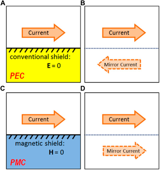
FIGURE 1. Illustration of how the method of mirror currents can be used to describe shielded currents. (A) A conventional shield with high electric conductivity (modeled as a perfect electric conductor) does not allow electric fields to penetrate. As a result, the tangential component of the electric field is zero at the boundary. (B) An out-of-phase mirror current at the opposite side of the shield (dotted line) satisfies the same boundary condition on the shield and realizes the same field distributions. (C) A magnetic shield (modeled as a perfect magnetic conductor) does not allow magnetic fields to penetrate. As a result, the tangential component of the magnetic field is zero at the boundary. (D) An in-phase mirror current at the opposite side of the shield (dotted line) satisfies the same boundary condition on the shield and realizes the same field distributions.
A magnetic shield [16, 17] is a shield that exhibits magnetic conductivity (instead of “normal” electric conductivity), which implies that the tangential component of the magnetic field is zero at the boundary. Eddy currents in a magnetic shield are described by in-phase mirror currents (see Figures 1C,D), which interfere constructively with the field produced by the coil. This increases the amount of field generated per unit current.
While true magnetic conductors do not exist in nature, they can easily be simulated with the Finite Difference Time Domain (FDTD) method [18]. Moreover, current RF technology is able to physically realize magnetic conductivity using metasurfaces. These two-dimensional structures with engineered electromagnetic boundary conditions consist of many periodically arranged passive circuits. Macroscopically, this results in extraordinary interactions with incident electromagnetic fields. A range of metasurfaces exist, known as artificial magnetic conductors (AMCs) or high-impedance surfaces (HISs), which exhibit high effective magnetic conductivity and surface impedance over a particular bandwidth [19–21]. These surfaces are often applied in the GHz range but can be adapted to operate at lower frequencies. Saleh et al. [22] have successfully applied such a structure to improve the B1+ efficiency of a stripline antenna at 7 T. Chen Zhichao et al. have used a HIS to improve the SAR efficiency of a loop antenna at 7 T [23]. They also report an increased SAR efficiency and homogeneity for a single dipole antenna backed by a HIS [24], compared to a copper shield. These improvements match closely the expected improvements when the HIS shield is replaced with a Perfect Magnetic Conductor (PMC) shield in a FDTD simulation. For an 8-channel dipole array at 7 T, the HIS results in only modest improvements on a homogeneous phantom, and on a heterogeneous head model, no improved SAR efficiency is reported [25]. Additionally, Chen Haiwei et al. [26] reported an increased SAR efficiency at 9.4 T when comparing a loop coil shielded by a magnetically conducting metasurface to the one with a plain copper shield.
Lezhennikova et al. [27] have investigated potential improvement of a birdcage head coil at 7 T using a slot resonator, which makes a section of the shield magnetically conductive. Using a 400 mm diameter birdcage, they found significant improvement in transmit efficiency using their slot resonator. However, a smaller conventional birdcage with 300 mm diameter still performed better, and the authors were unable to apply their slot resonator to this smaller coil. In other work, Lezhennikova et al. [28] described potential improvement of birdcage coils with RF shields of arbitrary impedance, and they designed an artificial magnetic shield for use in a small animal coil (Ø 70 mm) for 7 T. However, their resonant structure has a significant thickness, increasing the diameter of the total coil + shield to 140 mm, thus resulting in a solution that would not be practical to implement at 3 T, where bore space is precious.
This work explores the feasibility and potential improvements of a birdcage body coil at 3 T with a magnetic shield. For practical reasons, the final result at 3 T contains simulated results only, and various measurements at 7 T are performed to demonstrate the feasibility of our proposed solutions at 3 T. This work consists of three sections: The first section outlines the development of a magnetic shield at 7 T using flattened split ring resonators. Bench measurements and simulations are used to assess whether this shield is working as intended. The second section uses 3 T simulations to show that the birdcage needs to be adapted for use with a magnetic shield. This adaptation is implemented in a custom built birdcage at 7 T with 300 mm diameter. This birdcage is a scaled down version (by a factor of 7/3rd) of a birdcage body coil at 3 T and is used to demonstrate the feasibility of the required adaptation. Finally the third section compares simulated results of a birdcage body coil with magnetic shield to a conventionally shielded birdcage body coil at 3 T.
Theory
Figure 1 illustrates how the Eddy currents in a shield can be described using mirror currents for both Perfect Electric Conductor (PEC) and Perfect Magnetic Conductor (PMC) boundary conditions. The fields generated in the scanning subject (or phantom) are a superposition of the fields generated by the source current and the mirror current. Of course, in a practical situation, the amplitude of the mirror current will be lower than that of the source due to losses. Additionally, phase retardation due to the distance between the antenna and the shield must be taken into account. However, in general, the fields generated by an antenna with a PEC shield are caused by the difference (superposition with 180 phase difference) of two currents. Therefore, they will decay more rapidly with an increasing distance from the antenna, compared to those generated by unshielded or PMC-shielded antennas. Figure 2 shows the effect this has on the field of a birdcage coil: to reach a target B1 level in the center of the coil with a PEC shield, a strong current is required which results in strong electric fields in close proximity to the birdcage rungs. Note that a PEC shield reduces the amount of field generated per unit current, but not necessarily per unit power. Since the PEC shield reduces both B-fields and E-fields per unit current, the loading to the current decreases. As a result, generating 1 A of shielded current requires less power than 1 A of unshielded current.
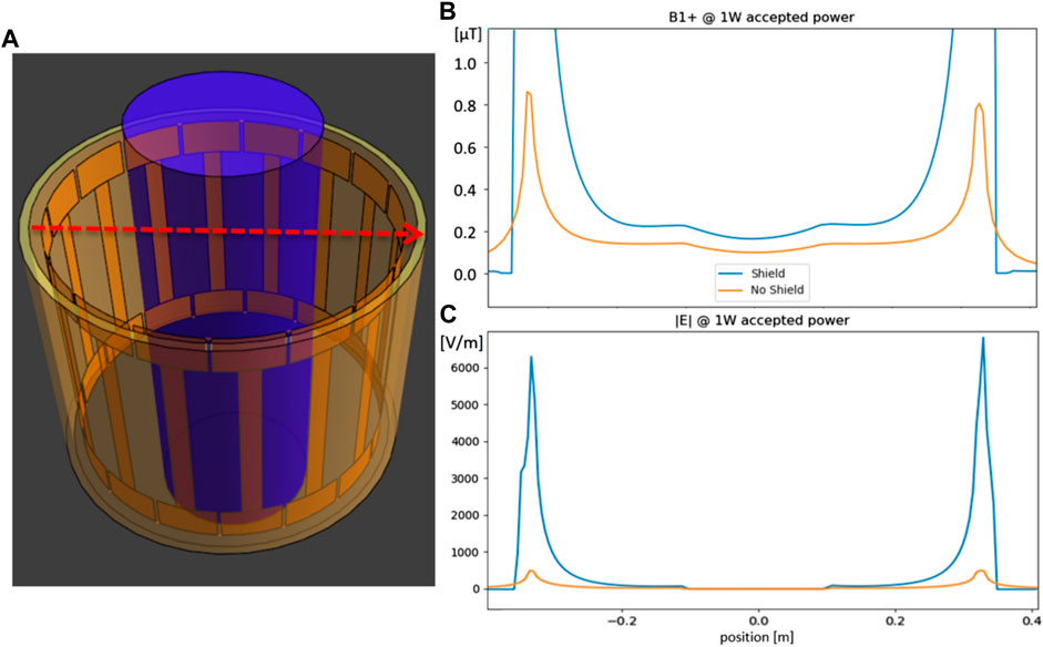
FIGURE 2. (A) example geometry of birdcage using FDTD simulation. Dotted red line indicates position of the profiles of (B) and (C). The loading phantom (blue cylinder) was given tissue-like properties. Birdcage dimensions are radius: 352 mm, rung length: 420 mm, endring width: 80 mm, rung width: 40 mm, and shield radius: 372 mm. (B) B1+ field strength profile with and without PEC shield. Since the fields are normalized to 1 W accepted power, the shield actually increases B1 because without a shield, more power is radiated away. (C) Electric field strength profile with and without shield.
To define what magnetic conductivity is, let us first review how electric conductivity is described using Ampère’s circuital law (in differential form and SI units),
Here, µ0 and ε0 refer to the vacuum permeability and permittivity, respectively. B and E refer to the magnetic and electric fields, and J is the electrical current density, describing the movement of electric charges. Analogously, we could write Faraday’s law of induction as
where we have introduced a “magnetic current” Jm that is normally absent in typical formulations of Faraday’s law. This magnetic current is entirely fictional: It describes the movement of magnetic monopoles, which do not exist, and therefore it is always zero. However, the second term
Methods
The Split Ring Shield
This section outlines the development and validation of the split ring shield, a magnetic shield suitable for MRI purposes at 7 T. Since the final application is a birdcage coil shield, uni-directional magnetic conductivity is considered sufficient where the magnetic conductivity will be oriented along the azimuthal direction following the circumference of the birdcage coil.
Designing the Split Ring Shield
Figure 3 illustrates the design process of our magnetic shield, designed to operate at 300 MHz. Split ring resonators were flattened and arranged in a periodic array and combined with a copper backplate to produce the Split Ring Shield (SRS). The dimensions of the rings (length: 360 mm, height: 4 mm) were determined via exploratory FDTD simulations: a plain dipole (length: 300 mm, width: 12 mm) is placed in front of a SRS design (oriented parallel to the resonator elements; see Figure 4), and the B1 field distribution is compared to a simulated dipole setup with an ideal magnetic shield (PMC). It was expected that beneficial reflective properties would occur in a bandwidth below the self-resonance frequency of the rings, which is around 380–400 MHz with these dimensions. Ideally, a somewhat longer length of around 420 mm would be preferred, bringing the resonance closer to (but still safely above) 300 MHz. However, the split ring resonator elements carry current, which causes the transmitted field to extend further in the z-direction than that of the dipole alone. Typical UHF MRI arrays are designed to generate fields over lengths up to 300 mm for body imaging (head imaging: ∼200 mm), and generating fields outside of a target region is inefficient. The length of 360 mm was chosen as a tradeoff between 300 and 420 mm.
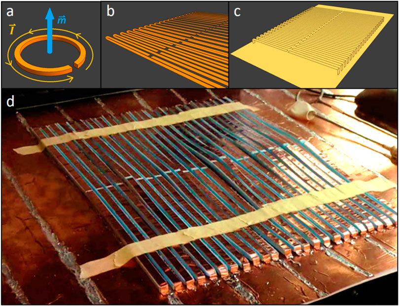
FIGURE 3. (A) A split ring resonator, which carries current and thus is able to capture a time-varying magnetic field. (B) Split ring resonators are flattened and arranged into a period array. (C) The split ring resonators are merged with a backplate and dubbed the “Split Ring Shield” (SRS). (D) Photograph of the SRS under construction. The rings are made by applying copper tape to foam spacers and soldered to a copper backplate. The dimensions are as follows: ring length: 360 mm, width: 6 mm, height: 4 mm, gap size: 2 mm, and ring spacing period: 10 mm.
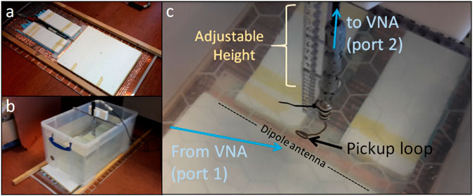
FIGURE 4. (A) Photograph of split ring shield with foam spacers and dipole antenna (length = 300 mm). (B) Measurement setup with SRS, dipole antenna, foam spacers, salt water tank (σ = 0.5 S/m), and pickup loop inside the water. (C) Close-up of the pickup loop positioned inside the water. The dipole is oriented in the z-direction, the loop position varies in the x-direction, and the loop is oriented in the xz-plane.
Measuring the Field of a Dipole Antenna With Magnetic Shield
Figure 4 shows photographs of the measurement setup. Reflective properties were measured by positioning a dipole antenna (length: 300 mm, width: 12 mm) close to the SRS (10 mm distance from the backplate) and parallel to the rings. A tank of salt water was positioned at 20 mm distance from the antenna. The dipole antenna was connected to the first port of a vector network analyzer (VNA). A pickup loop was positioned in the water and connected to the second port of the VNA, and transmission was measured at varying distance from the antenna by measuring S12 from 250 to 450 MHz. The distance between the antenna and the pickup loop was varied from 20 to 140 mm. The same measurements were performed with a conventional copper shield (at 10 mm distance from the antenna) and without a shield. Each measurement was performed multiple times. (without shield: 3 times, conventional shield: 5 times, SRS: 7 times)
To characterize how quickly the field decays with increasing distance from the antenna, we fit the following function to the data:
where x is the distance between the pickup loop and the antenna, and the exponential factor encompasses the reduction in field strength due to conductivity of the salt water, with β being the imaginary part of the wave propagation vector, computed using σ = 0.5 S/m and εr = 78 [29]. A and q are the free parameters, A representing the amplitude and q representing how rapidly the field falls off with distance, with higher q signifying a more rapid decay. For each measurement, this fit is performed at each frequency, and the q values of different measurements are averaged.
The measurement setup was also simulated using FDTD (Sim4Life, Zurich Medtech, Switzerland), where 6.6 MCells were used to model the dipole antenna, water tank (σ = 0.5 S/m, εr = 78), and shield. Each simulation was performed on the same grid. In addition to the SRS, conventional shield, and unshielded simulation, a simulation with a PMC shield was also performed. Again, in-depth B1 profiles were fitted to Eq. 3to arrive at a decay constant q as a function of frequency. Additionally, the source current magnitude was computed from the simulated fields and the B1 amplitude was taken at a point located 100 mm deep in the phantom on the central axis above the antenna to compute the current-efficiency in terms of B1 per unit current.
The Loading Problem and Multi Transmit Birdcages
This section outlines how the resonant mode of a birdcage coil gets disrupted if the conventional shield is replaced by a magnetic shield and presents a solution. To demonstrate the feasibility of this solution, it is implemented in an eight-channel (8Tx) birdcage shielded with the SRS at 7 T and used for in vivo imaging.
Simulations of Unloaded Birdcage Coils at 3 T
Initially, we will compare FDTD simulations of two unloaded high-pass birdcages at 3 T (128 MHz) with a conventional shield (modeled as a perfect electrical conductor, PEC) or a PMC shield. Both shields have a length of 600 mm and a radius of 372 mm. Initial tests showed that the setup with the PMC shield radiated energy (∼50% of input power in loaded condition) in the axial (±z) direction. To reduce these radiation losses, both shields were extended with 400 mm PEC sections on both sides, reducing radiation losses to <5% of input power for both setups in loaded condition. In the unloaded condition, there are no other losses (all copper is simulated as PEC and the shield as PEC or PMC) than radiation, which prevents the simulations from converging properly. To remedy this, the background medium (i.e., the “air”) of the simulation environment was given a small conductivity of 10–6 S/m. For both setups, the birdcage geometric properties are 16 rungs, radius: 352 mm, rung length: 420 mm, endring width: 80 mm, rung width: 40 mm, and shield radius: 372 mm. Both birdcage setups are tuned to 128 MHz and are simulated on the same grid (nvoxels = 153 * 153 * 69 = 1.615 MCells). Both simulations are run until a convergence level of −40 dB is reached. We will evaluate the B1+ and |E| field, with the two ports driven in quadrature (without any matching circuits) and normalized to accepted power (forward power−reflected power). Additionally, we will calculate the birdcage’s current efficiency in terms of B1+ in the isocenter per unit current in the rungs.
Simulations of Loaded Birdcage Coils at 3 T
To evaluate the performance of the birdcages in a more realistic situation, we load the birdcages with a cylindrical phantom (σ = 0.5 S/m, εr = 46, length: 1 m, and radius: 200 mm). As shown by the results, this severely dampens the required resonant mode of the birdcage with PMC shield due to increased resistance. Our solution to enforce the correct mode is to place a port in each of the birdcage’s rungs, yielding a 16Tx bandpass birdcage with PMC shield. This allows us to enforce the desired current pattern in the rungs regardless of the load. Subsequently, the capacitors in the endrings need to be optimized to make sure that the currents in the endrings are in the correct phase to contribute maximally to the B1+ field, when the rungs are driven in quadrature.
Construction of the 8Tx Birdcage at 7 T
We aim to investigate the potential improvements at 3 T via a downscaled model of a birdcage at 7 T. With the frequency increased by 7/3rd and all length scales reduced by the same factor, the two birdcages are described by the same physics. The reason behind this detour is merely practical: Adapting the shield of a 3 T birdcage body coil would require dismantling the MR system, severely hindering clinical operation and possibly voiding warranty. At the 7 T scanner, the smaller birdcage coil can be inserted, connected, and tested while leaving the scanner itself intact.
The SRS presented in Introduction (built on a flexible backplate) is curved into a cylindrical shape (diameter: 320 mm, total length: 500 mm). A birdcage coil with eight rungs (diameter: 300 mm, length: 250 mm, rung and endring width: 12 mm) is constructed on a Plexiglass former. Plastic spacers are attached to the shield to hold the birdcage in place. A port is inserted in every rung of the birdcage using SMB connectors, the female part of which was soldered onto a small PCB in the rung containing matching elements. Small holes were drilled in the shield through which the male part of the SMB connector was connected, allowing us to feed each rung individually using coaxial lines. Extra insulation was applied to prevent the connectors and matching elements from touching the SRS.
Tuning the 8Tx Birdcage
To find the optimal value of capacitors in the endrings of the birdcage, a series of FDTD simulations with a realistic human model (“Duke”, ITIS Foundation [30]) is performed with capacitance values ranging from 3 to 10 pF. The legs are chosen as an imaging target, mostly because the shoulders do not fit to enable head imaging. Also, the chosen setup has tissue in close proximity to the antenna, which poses a risk of creating SAR hotspots if a conventional birdcage were used, whereas a PMC shield birdcage would not have this problem. The rungs are driven in quadrature (45° phase increments between neighboring channels). Average B1, B1 homogeneity (σ/μ), and SAR efficiency (average B1/√peak SAR) are computed over the voxels containing tissue over a 180 mm FoV. The capacitance value that maximizes these metrics in simulations is considered optimal and will be used in the constructed 8Tx birdcage. For reference, the same setup is simulated using a conventional 2Tx birdcage (with the same dimensions) with PEC shield.
In-Vivo Measurements
The legs of a healthy volunteer are scanned by a 7 T scanner (Philips Achieva). Eight channels, corresponding to the eight birdcage rungs, are used for both transmission and reception. Transmit phases are determined by phase shimming on a dumbbell-shaped target region containing both legs. Anatomical scans are performed with the following parameters: Gradient echo, TE/TR = 4.935/11 ms; FA:10°, and voxelsize: 1 × 2 × 1 mm3. DREAM B1 amplitude maps are recorded with the following parameters: TE/TR = 1.97/14 ms, FA: 10o, steam FA: 60o, and voxelsize: 4.7x4.7x30 mm3. Local SAR was assessed based on simulated fields. The validity of simulated fields was assessed by comparing measured and simulated B1 maps.
The Simulated 16Tx Birdcage With PMC Shield at 3 Tesla
This section compares the performance of a sixteen-channel (16Tx) birdcage body coil with PMC shield to a conventional 2Tx birdcage with copper shield at 3 T (128 MHz) using FDTD simulations with a realistic human model.
For the 16Tx birdcage, the lumped elements in the endring do not necessarily have to be capacitive but may also need to be inductive for optimal performance. It is therefore referred to as endring reactance ΧER. To determine the optimal value of the endring reactance, a series of simulations is performed. In each simulation, a value of ΧER ranging from –j 12,433 Ω (0.1 pF) to + j 80 Ω (100 nH), as well as shorted and open connections, was assigned to all endring lumped elements. The rung currents are forced to produce a CP-mode by driving them with corresponding fixed phases using current sources, mimicking perfect matching. The birdcage is loaded with the cylindrical phantom mentioned in the section titled Simulations of loaded Birdcage coils at 3 T. Transmit efficiency (B1+/√Pacc) is evaluated by averaging over voxels contained in a spherical volume with 300 mm diameter around the origin. The value of ΧER, which yields the highest transmit efficiency, is considered optimal. By this procedure, we are effectively “tuning” the 16Tx birdcage with PMC shield.
In order to make a fair comparison of the transmit efficiency of the 16Tx birdcage with magnetic (PMC) shield versus a conventional 2Tx birdcage with conventional (PEC) shield, we will consider only fixed quadrature drive settings, i.e., 2Tx-PEC: [0, 90°], 16Tx-PMC: [0, 22.5, 45, … , 315, 337.5°]. This allows us to isolate the benefits of a magnetic shield from the inherent gains (and added complexity) that are associated with an increased number of transmit channels. Additionally, the fixed quadrature drive setting represents a more realistic use case of a 16Tx-PMC birdcage than using 16 channels in parallel transmit. If we allow the 16Tx coil to be driven with any phase setting, coupling will cause a significant portion of the forward power to be reflected, drastically increasing the amount of forward power required to reach the desired B1 level. With carefully designed matching circuits, it is possible to cancel all reflections for one particular drive setting, e.g., quadrature. In our simulations, we mimicked these perfect matching conditions by using current sources and normalizing to accepted power.
We compare the birdcages with PMC and PEC shields using FDTD simulations loaded with a realistic human model. The model is positioned for abdominal imaging with the isocenter of the coil coinciding with lumbar vertebra L4. The birdcage and shield dimensions and simulation parameters are the same as mentioned in the section titled Simulations of unloaded Birdcage coils at 3 T, except for the grid that is made finer (nvoxels = 285 * 383 * 334 = 36.46 MCells) to allow for accurate assessment of local SAR. Additionally, we will perform the same comparison in a “tissue-near-coil scenario” where Duke’s wrist is positioned close (∼8 mm) to the coil.
The various simulation setups that were outlined in the preceding paragraphs will be evaluated by a couple of metrics. First, the B1 field per unit current is extracted. This figure is expected to increase for PMC shielded coils. For the same B1 field, currents will be lower, and therefore, lower peak SAR levels are expected close to the coil structures. Transmit efficiency is defined as the B1+ field per unit power (|B1+|/√Pacc). This ultimately determines how much B1 is achieved for a given amount of deposited power. This metric also determines the global SAR; for larger transmit efficiency, the global SAR levels will be lower. Transmit homogeneity is defined as the average B1+ divided by the standard deviation. The final metric is the SAR efficiency, which is defined as the average B1+ divided by the square root of peak local SAR (average |B1+|/√ peak SAR10g). Average and standard deviation of B1+ are evaluated over all tissue within a 300 mm diameter sphere centered at the isocenter.
Results
Split Ring Shield
Figure 5A shows two examples of measured depth profiles, one obtained with a conventional shield (red) and one without a shield (blue). Fitted parameters A and q are also shown, and we see that with the conventional shield the value of q is higher, signifying a more rapid decay. Figure 5B shows the average values of q over the entire bandwidth, where we see that at each frequency, the conventional shield results in a more rapid decay than without a shield. The SRS is seen to exhibit resonant behavior around 380–400 MHz. Above the resonance frequencies, it functions poorly, showing rapid decay. Below the resonance frequencies, a large bandwidth exists where the q values measured with the SRS are lowest. Figure 5C shows q values resulting from fitting simulated data, which are in agreement with the measured values. A simulation with PMC shield is also included, which shows that decay profiles with PMC are very similar to the unshielded situation. All this shows that the SRS is working properly as a magnetic shield. The current-efficiency, computed from the simulated fields, was 0.39 μT/A with the PEC shield. With the SRS, the PMC shield, and no shield, the current efficiencies were 0.77, 1.35, and 1.05 μT/A, respectively. This shows that the SRS successfully increases the current-efficiency of the dipole antenna.
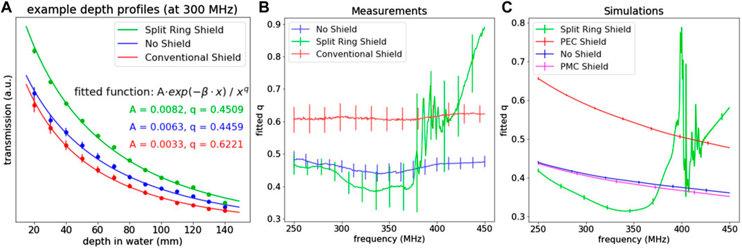
FIGURE 5. (A) Three example depth profiles of measured transmission at 300 Mhz with SRS (green), without shield (blue) and with conventional copper shield (red). Parameters A and q resulting from fitting Eq. 3 to these depth profiles are also shown. The numerical value of β is around 10.5 m−1 at 300 MHz. (B) Averages of fitted q from measured data as a function of frequency. (C) Fitted q from simulated data. Vertical bars signify 1σ error margins.
The Loading Problem and Multi-Transmit Birdcages
Simulations of Unloaded Birdcage Coils at 3 Tesla
Figure 6 shows simulated fields for two unloaded birdcages: one with a conventional shield and one with a magnetic shield. Both are high-pass birdcages, tuned to 128 MHz (3 T) and driven in quadrature by two ports located in the endrings. The lumped elements required to obtain the correct mode were 29.9 pF and 18.4 nH for the PEC and PMC birdcages, respectively. The simulation geometry is shown in Figure 6A, along with arrows indicating the positions of the transverse slices. The depicted transverse slices showing the B1+ distributions (Figures 6C,E) are located in the mid plane, but the electric field slices (Figures 6I,K) are located just above the bottom endring where the largest E-field components are located. In all slices, we see that the conventional birdcage generates stronger fields (normalized to accepted power) than the birdcage with magnetic shield, but from the table (Figure 6G), we see that the conventional birdcage requires disproportionally more current. This makes the birdcage with magnetic shield more efficient in terms of B1+ per unit current. Note that the choice to stabilize the unloaded simulations using slightly elevated air conductivity may cause an unknown bias in the italic values presented in the table (Figure 6G). However, the resulting current-efficiency does not depend on the type of losses that are included. The reasons for presenting these results are to show that the PMC-birdcage can be made to resonate in the correct mode and to compare the shape of the resulting field distributions. Another notable difference between the PEC and PMC cases lies in the homogeneity. From Figures 6C,H as well as the profiles shown in Figures 6F,L, we see that the field generated by the PEC-birdcage is homogeneous in the center but increases substantially in close proximity to the rungs. The fields of the PMC-birdcage are more uniform toward the edges. From Figure 6D, we see that the volume where the PMC-birdcage generates a homogeneous B1+ field extends further in the z-direction than with the PEC-birdcage.
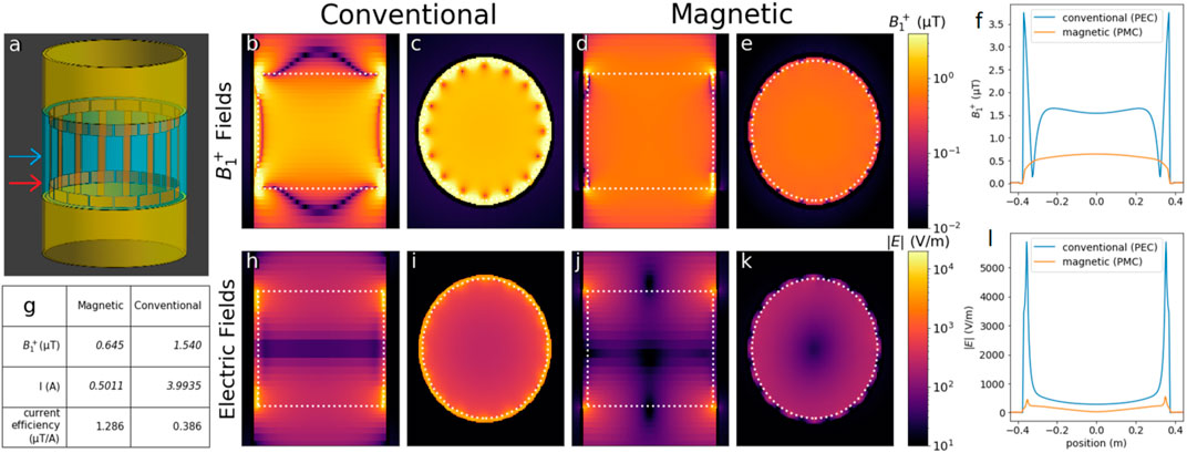
FIGURE 6. Unloaded birdcage coil field distributions with the conventional (PEC) or magnetic (PMC) shield at 128 MHz. (A) Simulation geometry. The part of the shield simulated as either the conventional or magnetic shield is depicted in blue. The yellow part was PEC for both scenarios. The red arrow indicates the position (z = 200 mm) of the transverse slices (I,K) and profile (L) of the electric fields. The blue arrow indicates the position (z = 0) of the transverse slices (C,E) and profile (F) of the B1 fields. (B–E) Mid-sagittal and transverse slices of the B1+ fields of the birdcages with conventional (B,C) and magnetic shield (D,E). (H–K) Mid-sagittal and transverse slices of the electric fields of the birdcages with conventional (H,I) and magnetic shield (J,K). The white dashed line denotes the birdcage outline. (F,L) Transverse profiles of B1 and electric fields, respectively, at height indicated by the arrow in (A). (G) Table summarizing the B1+ field strength in the center and required current, as well as their ratio. Currents are computed by numerically integrating the Ampère–Maxwell equation. The value listed here is the maximum of the magnitude of the currents in the rungs. All results are normalized to 1 W of accepted power.
Simulations of Loaded Birdcage Coils at 3 Tesla
Figure 7 shows simulated B1+ and electric fields similar to Figure 6, but now the birdcages are loaded with a phantom. The conventional birdcage (Figures 7A,B,F,G) still has a homogeneous field, but the birdcage with magnetic shield (Figures 7C,D,H,I) does not. In Figures 7C,H, we see a strong field in the bottom right corner, close to where the port is located. In Figures 7D,I, we see that only the rungs next to the ports produce a significant B1+ field. The profiles of Figures 7E,J also show asymmetric field distributions for the birdcage with magnetic shield. This is caused by increased resistance due to the larger current efficiency, as illustrated by Figure 8. Figures 8A,B show current distributions over the 16 rungs of the birdcage with magnetic shield in loaded and unloaded conditions. In Figure 8A, only one port is active, and in Figure 8B, two ports are active and driven with a 90° phase difference. The characteristic sinusoidal pattern, used to construct the CP-mode, can still be seen but the amplitude is much lower. In fact, the current only has high amplitudes in the rungs adjacent to the feeding port(s). Figure 8C shows the reflection coefficients S11 and S12 at one of the ports of the birdcage with magnetic shield in loaded and unloaded situations. In the unloaded situation, a resonant mode is observed at 128 MHz. In the loaded situation, the mode is shifted to 133 MHz, but the increased resistance lowers the Q-factor such that it can hardly be observed.
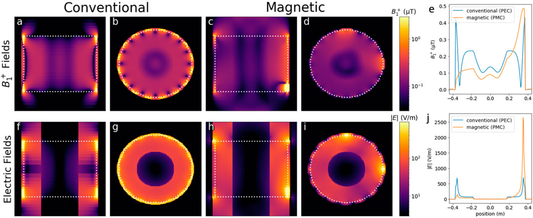
FIGURE 7. Loaded birdcage coil field distributions with the conventional [PEC, (A,B,F,G)] or magnetic [PMC, (C,D,H,I)] shield. (A–D) B1+ field distributions. (F–I) electric field distributions. (A,C,F,H) Sagittal slices. (B,D,G,I) transverse slices. For the B1+ distributions, both the sagittal and transverse slices are positioned at the origin (x = 0 or y = 0). The transverse slices of the electric fields are positioned at z = 200 mm (see Figure 6A). The white dashed line denotes the birdcage outline. (E,J) transverse profiles of B1 and electric fields, respectively, at the same height as the transverse slices. All results are normalized to 1 W of accepted power.
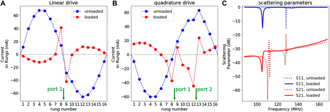
FIGURE 8. (A) Current distributions in the rungs of the birdcage with magnetic (PMC) shield in loaded (frequency = 133 MHz) and unloaded (frequency = 128 MHz) conditions, with one port active. (B) Idem with two ports active, driven in quadrature. The currents were calculated from the electric and magnetic fields by numerically integrating the Ampère–Maxwell equation over a rectangular path (in the central transverse plane) enclosing the rung. Here shown is the real part of the phasor. All results are normalized to 1 W of accepted power. (C) Scattering parameters of the birdcage with magnetic shield in loaded and unloaded situations.
The 8Tx Birdcage at 7 Tesla
The bottom row of Figure 9 shows results of the tuning process, plotting various metrics versus endring capacitance value. We see that all metrics have their maximum value around a capacitance of 7 pF, so this is the value that was used in the constructed birdcage. The left part of Figure 10 compares the performance of the 8Tx birdcage with SRS to a conventional 2Tx birdcage with the same dimensions. Overall, the two coils showed similar performance. We see that the conventional birdcage produces a slightly higher average B1 but much higher peak SAR values, resulting in a marginally better SAR efficiency for the birdcage with SRS. These metrics are summarized in the table (Figure 10G), which also shows the maximum current amplitudes found in both the rungs and endrings of the birdcage. The right part of Figure 10 shows in vivo results, demonstrating the feasibility of the concept of a multi-transmit birdcage. The scattering matrix of the 8Tx birdcage with SRS can be found in the supplementary material as Supplementary Figure S1.
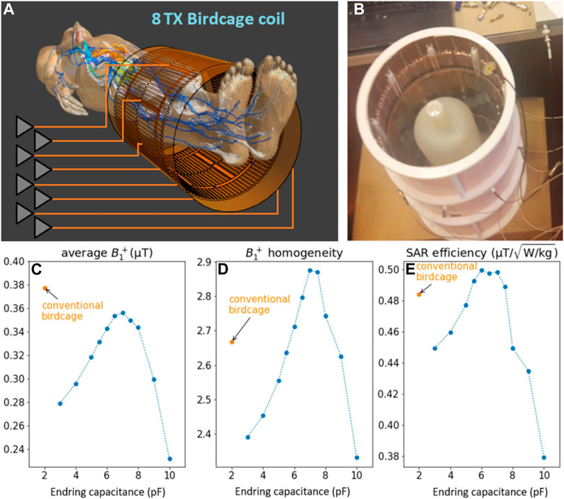
FIGURE 9. (A) 8Tx birdcage coil with SRS in FDTD simulation environment (Sim4Life) with a feeding port located in each rung. (B) photograph of the 8Tx birdcage coil with SRS and a loading phantom. The ports are connected through small holes in the shield. (C–E) “Tuning” the 8Tx birdcage. Simulated (at 300 MHz) values of average B1+ (C), homogeneity (D) and SAR efficiency (E) are shown as a function of endring capacitance value. Values obtained with a conventional birdcage (with the same dimensions as the 8Tx birdcage) are also shown for reference. All results are normalized to 1 W accepted power.
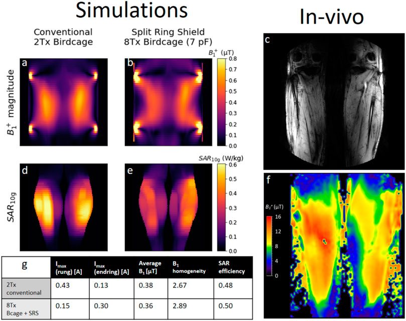
FIGURE 10. Overview of results obtained using 8Tx birdcage with SRS. Left: simulated B1 distributions (A,B) and 10-g averaged SAR distributions (D,E) comparing the 8Tx birdcage with SRS to a conventional 2Tx birdcage with PEC shield. (G) Table summarizing metrics computed from simulated fields. All simulated fields are normalized to 1 W accepted power. Right: In-vivo results obtained using 8Tx birdcage with SRS. (C) Anatomical image. (F) DREAM-B1 map obtained with 1,257 W of accepted power.
The 16Tx Birdcage With PMC Shield at 3 Tesla
Figure 11A depicts the model of the 16Tx birdcage at 3 T with a phantom load used for tuning and the locations of the ports indicated by red dots. Figure 11B shows the result of the tuning process, similar to Figure 9. The average B1+ magnitude is plotted for various values of endring reactance. The optimal values are those where the absolute magnitude of the reactance is high: small capacitance, high inductance, or open connections. For symmetry and stability reasons, we decided to use a lumped capacitance of 1 pF in the endring gaps.
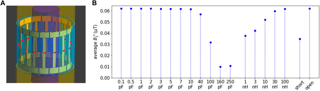
FIGURE 11. 16Tx PMC-birdcage. (A) Simulation geometry. The locations of the ports are denoted by red dots in the rungs. The magnetically conducting part of the shield is shown in blue, and the yellow part is modeled as PEC. The cylindrical phantom (εr = 46, σ = 0.5 S/m) is shown in purple. (B) Average B1+ as a function of endring reactance. The ports were simulated as harmonic current sources, driven in quadrature. The field was evaluated in a spherical volume of 300 mm diameter about the isocenter and normalized to 1 W of accepted power.
Figure 12 shows field distributions for the conventional 2-port birdcage with conventional shield (left) and 16-port birdcage with magnetic shield (right). Both birdcages are driven in quadrature. The top row shows B1+ distributions in transverse and coronal slices. The bottom row shows maximum intensity projections of the 10-g-averaged SAR distributions in coronal and transverse planes. The table (Figure 12I) summarizes the relevant metrics. The birdcage with magnetic shield has 27% lower B1+ magnitude and 33% lower peak local SAR resulting in a SAR efficiency (average B1+/√peak SAR) that is 11% lower. However, the magnetic shield does increase homogeneity by 13%.
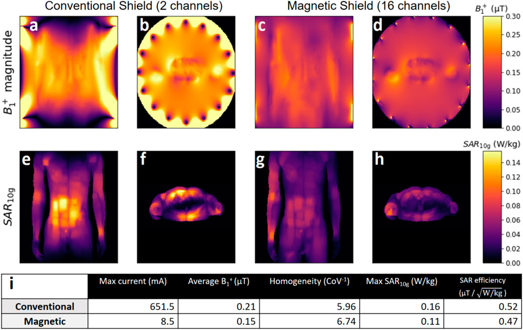
FIGURE 12. Field distribution in the birdcage coils with conventional [PEC, (A,B,E,F)] and magnetic [PMC, (C,D,G,H)] shield. The top row shows coronal (A,C) and transverse (B,D) slices of the B1+ distribution. The bottom row shows maximum intensity projections of the 10-g averaged local SAR distributions projected to the coronal (E,G) and transverse (F,H) plane. The table (I) summarizes important metrics calculated from the fields. Maximum current values are found in the endrings of the PEC-birdcage but in the rungs of the PMC-birdcage. All fields are normalized to 1 W of accepted power.
Figure 13 shows field distributions similar to Figure 12, but this time, the model’s arm has been repositioned such that it is close (8 mm) to one of the endrings. The bottom row shows that this causes a local SAR hotspot to appear in the lower arm when a conventional shield is used but not with a magnetic shield. The birdcage with magnetic shield again yields lower (25% less) B1+ per unit power, but the peak local SAR is almost three times higher with the conventional shield. This results in the birdcage with magnetic shield having a 27% higher SAR efficiency, as can be seen in table (Figure 13I). Additionally, the magnetic shield again results in a slightly more homogeneous (6%) transmit field.

FIGURE 13. Same as Figure 12, except for the fact that the model now has his hand close (∼8 mm) to one of the endrings. Field distribution in the birdcage coils with conventional [PEC, (A,B,E,F)] and magnetic [PMC, (C,D,G,H)] shield. The top row shows coronal (A,C) and transverse (B,D) slices of the B1+ distribution. The bottom row shows maximum intensity projections of the 10-g averaged local SAR distributions projected to the coronal (E,G) and transverse (F,H) plane. The table (I) summarizes important metrics calculated from the fields. Maximum current values are found in the endrings of the PEC-birdcage but in the rungs of the PMC-birdcage. All fields are normalized to 1 W of accepted power.
Discussion
The Split Ring Shield
The resonator length of 360 mm was chosen as a tradeoff between 300 and 420 mm. Of course, various strategies can be employed to reduce the resonance frequency of the resonators without increasing their total length, and there exist MRI applications where a 420 mm FOV is desired, but these are outside the scope of this proof-of-concept study. However, note that scaling these dimensions by 7/3rd results in 840 mm long resonators (and fields extending equally far in z-direction) at 3 T, so if applied at 3 T, the current implementation would have to be adapted to reduce resonator length.
In both bench measurements and simulations, the SRS significantly reduces the rate at which the field of a dipole antenna decays. However, its behavior somewhat differs from that of a PMC. The field of the dipole with PMC closely resembles that of the unshielded dipole antenna. This is expected, as the field produced by two closely located in-phase current sources is essentially the same as the field produced by a single current source. More surprising is that the SRS outperforms the unshielded situation over a large bandwidth. This may be caused by the fact that the SRS is longer than the dipole, and the resonators of the SRS carry current over their total length. Thus, the spatial extent of the current that generates the field is larger, resulting in less rapid decay.
Overall, the SRS behaves like a magnetic shield at 300 MHz in the sense that it reduces the decay rate of the field produced by a dipole antenna, when compared to a conventional copper shield. Additionally, the SRS reduces the current of the dipole antenna, increasing the amount of field generated per unit current. However, by design, the magnetic conductivity of the SRS is anisotropic: if the source current is not oriented parallel to the resonators of the shield, no magnetic conductivity is seen.
The Loading Problem and Multi-Transmit Birdcages
A drawback of the magnetic shield is that the resistance due to loading is increased. In a birdcage coil with conventional shield, the energy delivered by the port is allowed to propagate around the birdcage in the azimuthal direction with little loss due to loading. The propagating waves form a distinct resonance mode setting up the desired sinusoidal current pattern. With a magnetic shield but without loading, this is still the case, as shown in Figures 6, 8. However, when the birdcage with magnetic shield is loaded, the resistance increases dramatically. This follows from the definition of resistance as
In situations with weaker loading than described in this work (e.g., children in a 3 T scanner whole body birdcage, a head in a 400 mm birdcage at 7 T or small animal scanners [28]), this loading problem will be less severe. The energy can propagate in the azimuthal direction without too much losses, which results in a sinusoidal current pattern over the rungs. An example is provided by Lezhennikova et al. [27] where a 400 mm diameter birdcage coil with magnetic shield loaded by a human head at 7 T did not severely disrupt the sinusoidal current pattern.
As a solution, we propose a multi-transmit birdcage with one port in each rung, which allows us to enforce the CP-mode, regardless of loading. An eight-channel birdcage with 300 mm diameter, shielded with the SRS, has been constructed and successfully used for imaging at 7 T. Simulations show this 8Tx birdcage with SRS has similar performance as a conventional birdcage of the same dimensions. It achieves slightly lower average B1 with a lower peak SAR value, resulting in a slightly higher SAR efficiency, but the differences are small. Both in simulations and in vivo, the 8Tx birdcage with SRS achieved B1 amplitudes ranging from 0.23 to 0.45 μT (normalized to 1 W accepted power), providing confidence in the validity of the simulated fields. Due to the anisotropic magnetic conductivity of the SRS, it exhibits a different surface impedance for the z-oriented currents in the rungs than for the azimuthally oriented currents in the endrings. For this reason, the table (Figure 10G) vshows the maximum values of rung and endring currents separately. Compared to the conventional birdcage, the current in the rungs is much lower, but the current in the endrings is actually higher with the SRS. This strongly mitigates the benefit of the magnetic shield in this specific case: in Figure 10E, we see the peak SAR value occurs in the leg close to the endring. This implementation of a birdcage with magnetic shield is therefore suboptimal for reducing SAR hotspots. However, it does successfully demonstrate the feasibility of a birdcage with magnetic shield using a multi-transmit drive configuration to enforce the CP mode with a sinusoidal current pattern over the rungs.
The 16Tx Birdcage With PMC Shield at 3 Tesla
This work explored the use of a magnetic shield to improve the performance of a birdcage body coil at 3 T. The main advantage provided by a magnetic shield is an increased efficiency in terms of B1+ per unit current. A conventional birdcage can create SAR hotspots close to the endrings due to strong currents. With a magnetic shield, the currents are lower, which eliminates these SAR hotspots near the rungs and endrings. The magnetic shield reduces B1+ efficiency but substantially reduces peak local SAR if tissue is present in close proximity to the coil, increasing the SAR efficiency by 27%. This tissue-near-coil scenario is a potentially realistic situation since patients are, in principle, free to place their arms in a position that is comfortable (as long as they do not create current loops), possibly on the bore lining and close to the birdcage coil.
The current IEC guidelines [5] only limit global SAR when a volume coil, such as a birdcage body coil, is used. However, our results confirm the findings from other studies [6–12] that local SAR can reach considerably high levels although global SAR levels are kept within the limits. Results show that, in particular, a posture with the hand of the patient close to the birdcage ring may result in excessively high SAR levels. The same may hold for obese patients where parts of the body will inherently be close to the rings. Results have shown that a 16Tx birdcage body coil with magnetic shield requires much lower currents to reach the same B1 level, which translates into much more lenient SAR levels in body parts close to the coil conductors. However, the reduced transmit efficiency of ∼25% indicates that in order to reach the same B1+ level with a magnetic shield, the whole-body SAR will be ∼1.8 times higher.
To investigate the potential benefit of a magnetic shield for a 3 T birdcage body coil, we chose to perform the comparison in an idealized situation with a PMC shield. No copper losses were included in any of the simulations. Of course, a physical implementation of an artificial magnetic conductor is associated with losses, but the exact loss performance depends very much on the specific implementation. However, the lower currents in the birdcage (as a result of field-per-current efficiency) with a magnetic shield indicate that ohmic losses in the birdcage coil will be lower if a magnetic shield is used. Furthermore, a PMC reflects incoming electromagnetic waves from all incident angles and polarizations with perfect 0° phase, whereas AMCs have a reflection coefficient of which the magnitude and phase depend on the incident angle and polarization. Often times, a tradeoff exists between losses, angle independence, and thickness of the structure. Based on AMC implementations at higher field strengths [23–26], we suggest a patch-based approach with vias, but more research is needed to determine which AMC structure would be most suitable for MRI. For example, the implementation by Chen Zhichao [23–25] uses a thicker structure, but the implementation by Chen Haiwei [26] might be more lossy due to the presence of lumped capacitors.
The practical realization of a 16Tx birdcage body coil with magnetic shield is first of all impeded by the clinical workflow, which does not allow the adaptation of any of our scanners. Without this obstacle, it would still pose a considerable engineering challenge. The 16Tx drive could be achieved using a Butler matrix to distribute the power over the rungs. Note that while the coupling between ports is relatively low due to the increased load with magnetic shield, still coupling levels of up to −6 dB are present (see Supplementary Figure S2). Therefore, the matching circuits in each rung need to be designed such that they negate all reflections caused by coupling for one particular drive setting (CP-mode). By employing current sources driven with fixed phases, this simulation study essentially mimics perfect matching conditions and considers only the effect of the magnetic shield itself.
By using a PMC as a magnetic shield and assuming perfect matching conditions for the 16Tx setup, we have assumed two “best case” scenarios for our birdcage with magnetic shield. Still the final result is ambiguous: Though the 16Tx PMC-birdcage successfully reduces SAR hotspots in the periphery, the reduced transmit efficiency makes the coil inferior for most applications. Note that imperfections in realistic magnetic shield implementations may further deteriorate the efficiency as reported here.
The birdcage coil dimensions used in this work were derived from an actual 3 T system. Dimensions with the conventional and magnetic shield were kept the same to study the effect of the magnetic shield only. However, the 16Tx birdcage coil with magnetic shield yields a remarkably large field-of view in the z-direction of almost 1 m. This explains the lower B1+ efficiency for the birdcage coil with magnetic shield. Subsequent efforts will focus on adaptations of the system such that more field focusing is achieved with a magnetic shield. However, preliminary findings (shown in the supplementary material under “Additional Setups”) indicate that this is not trivial. Reduction of the birdcage dimension and/or the shield length do not suffice (see Supplementary Figure S3). There are situations where this longer B1 field is advantageous, such as whole-body imaging. At higher field strengths, the “long” transmit field of a magnetically shielded coil becomes comparable to the FOV of the scanner, and similar transmit efficiencies can be achieved with a magnetic or conventional shield, as shown in The loading problem and multi-transmit birdcages (Figure 10). However, for a typical 3 T birdcage, the FOV is maximally 500 mm, and a B1 field that extends for almost 1 m in z-direction is not efficient.
One might argue that the investigated 16Tx birdcage is similar to a phased array of dipoles and that similar performance gains (improved SAR efficiency and homogeneity) can be achieved in a simpler way using dipoles and a magnetic shield. However, in our 16Tx birdcage, the endrings do carry some current (albeit much less than with a conventional 2Tx birdcage), which adds to the produced B1 field. Simulations show that plain dipoles with a magnetic shield perform worse than our 16Tx birdcage with a magnetic shield, which can be seen in Supplementary Table S1. This indicates that some capacitive coupling between the rungs through the endrings still adds to the B1+ efficiency.
Since a conventional birdcage is shown to exhibit SAR hotspots close to the endrings, one might argue that removing the ports from the endrings and placing a port in each rung is already enough to remove these hotspots, without the need for a magnetic shield. We have performed additional simulations to show that this is not the case. As can be seen in Supplementary Table S1, a 16Tx birdcage with conventional shield and a port in each rung performs worse than a regular 2Tx birdcage.
Maximum current values are found in the endrings of the PEC-birdcage but in the rungs of the PMC-birdcage. We realize that the model’s hand is positioned close (<1 cm) to one of the endrings and not necessarily close to the rungs (∼4.5 cm), possibly resulting in a bias towards the PMC-birdcage where the rungs carry most current. To test this, we have performed the same simulations again but with Duke rotated such that his hand is now close to the rung as well. The results (shown in Supplementary Figure S4) were slightly different but did not change the significance of our results.
The purpose of this study was to investigate whether the application of a magnetically conducting shield could improve the performance of a birdcage coil. Other studies [22–26] have demonstrated improved performance for local transmit antennas by using a magnetically conducting shield, but for the birdcage coil at 3 T, this has not been investigated. Lezhennikova et al. [27, 28] have investigated potential improvements of birdcage coils with a magnetic shield under weaker loading conditions, where no adaptation to the driving scheme is required. However, they have not investigated potential SAR hotspots in any scenario where tissue is present close to one of the conductors, which was the focus of this work. Our results indicate that the magnetic shield substantially reduces the current required to produce B1+ field, which reduces the strong electric fields near the coil. However, birdcage coils traditionally use a resonant mode to set up the desired current pattern efficiently. The improved current efficiency of the magnetically shielded birdcage associated with increased load resistance severely dampens the resonant mode. Therefore an alternative driving scheme is employed to restore the CP mode. The magnetic shield reduces peak local SAR by a factor of three in a tissue-near-coil scenario. However, in both the standard scenario and the tissue-near-coil scenario, the magnetic shield reduces the B1+ efficiency from 0.20 to 0.21 to 0.15 µT/√W. Thus, using a magnetic shield reduces the SAR efficiency (B1+/√ peak local SAR) from 0.52 to 0.47 µT/√(W/kg) in the standard scenario, but it increases the SAR efficiency from 0.38 to 0.48 µT/√(W/kg) in the tissue-near-coil scenario. Nevertheless, for general applications where a large field of view is not required, the magnetically shielded birdcage body coil is still inferior to a conventional birdcage body coil because of the reduced B1+ efficiency and concomitant increased global SAR levels.
Conclusion
The birdcage body coil with a conventional (electric) shield requires large currents to reach sufficient B1+ inside the patient. These large currents may cause severe SAR hotspots in parts of the patient that are close to the birdcage endrings. This study explores the possibility of improving a birdcage body coil using a magnetic shield. A magnetic shield using split ring resonators, suitable for MRI at 7 T, is developed and tested. Magnetic shields make antennas much more current-efficient, which reduces the required current amplitudes. However, this larger efficiency also results in severely increased loading of the coil. In the case of a birdcage coil, this dampens the required operation mode. This can be addressed by driving the birdcage coil at each rung separately, resulting in a multi-transmit birdcage coil. The feasibility of this concept is demonstrated by constructing an 8Tx birdcage with magnetic shield at 7 T. Its feasibility is demonstrated by in vivo leg imaging while FDTD simulations show that the magnetic shield birdcage has similar B1+ efficiency and larger SAR efficiency than a conventional birdcage counterpart. At 3 T, a simulation study comparing a 16Tx birdcage coil with magnetic shield to a conventional 2Tx birdcage coil has been conducted for a standard imaging posture and a posture where the hand of the patient model is positioned close to the endring (tissue-near-coil scenario). Results show that local SAR hotspots in extremities close to the endrings can be avoided using a birdcage with magnetic shield. However, the increased longitudinal field of view results in reduced transmit efficiency, which effectively renders the magnetically shielded birdcage coil as presented in this study still inferior to the current state-of-the-art for general application.
Data Availability Statement
The raw data supporting the conclusions of this article will be made available by the authors, without undue reservation.
Ethics Statement
Ethical review and approval was not required for the study on human participants in accordance with the local legislation and institutional requirements. The patients/participants provided their written informed consent to participate in this study.
Author Contributions
CvL performed the simulations, with help of BS. CvL wrote the article, with help of BS and AR. CvL and ML performed the bench measurements with the shielded antennas. CvL, BS, and AR performed the in vivo measurements. SG and KS contributed to the conception of the idea and helped interpret the results. CvdB and DK aided in data acquisition and interpretation. All authors contributed to revising the article.
Funding
This project has received funding from the European Union’s Horizon 2020 research and innovation program under grant agreement No 736937.
Conflict of Interest
ML was employed by the company Tesla Dynamic Coils.
The remaining authors declare that the research was conducted in the absence of any commercial or financial relationships that could be construed as a potential conflict of interest.
Publisher’s Note
All claims expressed in this article are solely those of the authors and do not necessarily represent those of their affiliated organizations, or those of the publisher, the editors and the reviewers. Any product that may be evaluated in this article, or claim that may be made by its manufacturer, is not guaranteed or endorsed by the publisher.
Supplementary Material
The supplementary material for this article can be found online at: https://www.frontiersin.org/articles/10.3389/fphy.2021.716521/full#supplementary-material
References
1. Hayes CE, Edelstein WA, Schenck JF, Mueller OM, Eash M. An Efficient, Highly Homogeneous Radiofrequency Coil for Whole-Body NMR Imaging at 1.5 T. J Magn Reson (1969) (1985) 63:622–8. doi:10.1016/0022-2364(85)90257-4
2. Hayes CE, Eash MG. Shield for Decoupling RF and Gradient Coils in an NMR Apparatus. US Patent (1987) 4:642.
3. Roemer PB, Edelstein WA. Double‐sided RF Shield for RF Coil Contained within Gradient Coils of NMR Device. US Patent (1989) 4:879.
4. Jin J. Electromagnetic Analysis and Design in Magnetic Resonance Imaging. Boca Raton, Florida: CRC Press (1998):164–90.
5.IEC 60601-2-33:2010+AMD1:2013+AMD2:2015. Medical Electrical Equipment - Part 2-33: Particular Requirements for the Basic Safety and Essential Performance of Magnetic Resonance Equipment for Medical Diagnosis. Geneva, Switzerland: International Electrotechnical Commission (IEC) (2015).
6. Shrivastava D, Utecht L, Tian J, Hughes J, Vaughan JT. In Vivo radiofrequency Heating in Swine in a 3T (123.2-MHz) Birdcage Whole Body Coil. Magn Reson Med (2013) 72(4):1141–50. doi:10.1002/mrm.24999
7. Nadobny J, Klopfleisch R, Brinker G, Stoltenburg-Didinger G. Experimental Investigation and Histopathological Identification of Acute thermal Damage in Skeletal Porcine Muscle in Relation to Whole-Body SAR, Maximum Temperature, and CEM43 °C Due to RF Irradiation in an MR Body Coil of Birdcage Type at 123 MHz. Int J Hyperthermia (2015) 31(4):409–20. doi:10.3109/02656736.2015.1007537
8. Murbach M, Neufeld E, Cabot E, Zastrow E, Córcoles J, Kainz W, et al. Virtual Population‐based Assessment of the Impact of 3 Tesla Radiofrequency Shimming and Thermoregulation on Safety and B1+ Uniformity. Magn Reson Med (2015) 76:986–97. doi:10.1002/mrm.25986
9. Murbach M, Zastrow E, Neufeld E, Cabot E, Kainz W, Kuster N. Heating and Safety Concerns of the Radio-Frequency Field in MRI. Curr Radiol Rep (2015) 3:45. doi:10.1007/s40134-015-0128-6
10. Fiedler TM, Ladd ME, Bitz AK. SAR Simulations & Safety Neuroimage. Neuroimage (2018) 168:33–58. doi:10.1016/j.neuroimage.2017.03.035
11. Murbach M, Cabot E, Neufeld E, Gosselin M-C, Christ A, Pruessmann KP, et al. Local SAR Enhancements in Anatomically Correct Children and Adult Models as a Function of Position within 1.5 T MR Body Coil. Prog Biophys Mol Biol (2011) 107(3):428–33. doi:10.1016/j.pbiomolbio.2011.09.017
12. Seifert F, Wübbeler G, Junge S, Ittermann B, Rinneberg H. Patient Safety Concept for Multichannel Transmit Coils. J Magn Reson Imaging 26:1315–21. doi:10.1002/jmri.21149
13. Foo TK, Hayes CE, Kang Y. An Analytical Model for the Design of RF Resonators for MR Body Imaging. Magn Reson Med (1991) 21:165–77. doi:10.1002/mrm.1910210202
14. Foo TK, Hayes CE, Kang Y. Reduction of RF Penetration Effects in High Field Imaging. Magn Reson Med (1992) 23:287–301. doi:10.1002/mrm.1910230209
15. Liu W, Zhang S, Collins CM, Wang J, Smith MB. Comparison of Four Different Shields for Birdcage-type Coils with Experiments and Numerical Calculations. Concepts Magn Reson B Magn Reson Eng (2006) 29B(4):176–84. doi:10.1002/cmr.b.20073
16. Engheta N, Ziolkowski R. Metamaterials Physics and Engineering Explorations. chapters 2.8, 11.3. Hoboken, New Jersey: John Wiley & Sons (2006).
17. Capolino F. Theory and Phenomena of Metamaterials. chapter 4. Milton Park, Oxfordshire: Taylor & Francis Group (2009).
18. Gedney S. Introduction to the Finite-Difference Time-Domain (FDTD) Method for Electromagnetics. an Rafael, CA: Morgan & Claypool Publishers (2011):63.
19. Sievenpiper D, Zhang L, Broas RFJ, Alexopolous NG, Yablonovitch E. High-impedance Electromagnetic Surfaces with a Forbidden Frequency Band. IEEE Trans Microwave Theor Tech (1999) 47(11):2059–74. Nov. doi:10.1109/22.798001
20. Simovski CR, Sochava AA. High-impedance Surfaces Based on Self-Resonant Grids. Analytical Modelling and Numerical Simulations. Prog Electromagnetics Res PIER (2003) 43:239–56. doi:10.2528/pier03042801
21. Goussetis G, Feresidis AP, Vardaxoglou JC. Tailoring the AMC and EBG Characteristics of Periodic Metallic Arrays Printed on Grounded Dielectric Substrate. IEEE Trans Antennas Propagation (2006) 54(1):82–9. doi:10.1109/tap.2005.861575
22. Saleh G, Solbach K, Rennings A. EBG Structure to Improve the B1 Efficiency of Stripline Coil for 7 Tesla MRI. In: 2012 6th European Conference on Antennas and Propagation (EUCAP); 2012 26–30 march; Brussels, Belgium (2012) p. 1399–401. doi:10.1109/EuCAP.2012.6206267
23. Chen Z, Solbach K, Erni D, Rennings A. Improving B1 Efficiency and Signal-To-Noise-Ratio of a Surface Coil by a High-Impedance-Surface RF Shield for 7-T Magnetic Resonance Imaging. IEEE Trans Microwave Theor Tech (2017) 65(3):988–97. doi:10.1109/tmtt.2016.2631169
24. Chen Z, Solbach K, Erni D, Rennings A. Improved B1 Distribution of an MRI RF Coil Element Using a High-Impedance-Surface Shield. In: 2015 German Microwave Conference; 2015 16–18 march; Erlangen, Germany (2015) p. 111–4. doi:10.1109/gemic.2015.7107765
25. Chen Z, Solbach K, Erni D, Rennings A. Electromagnetic Field Analysis of a Dipole Coil Element with Surface Impedance Characterized Shielding Plate for 7-T MRI. IEEE Trans Microwave Theor Tech (2016) 64(3):972–81. doi:10.1109/tmtt.2016.2518168
26. Chen H, Guo L, Li M, Liu C, Shan S, Wang Y, Weber E, Liu F, Crozier S. Metamaterial RF Shield with Reduced Specific Absorption Rate and Improved Transmit Efficiency for 9.4 T MRI. In: Proceedings of ISMRM; 2018 16–21 june; Concord, California (2018).
27. Lezhennikova K, Simovski C, Abdeddaim R, Balafendiev R, Glybovski S. Extending a Birdcage Coil for Magnetic Resonance Imaging of a Human Head with an Artificial Magnetic Shield. Photon Nanostructures - Fundamentals Appl (2021) 43:100890. doi:10.1016/j.photonics.2020.100890
28. Lezhennikova K, Abdeddaim R, Hurshkainen A, Vignaud A, Dubois M, Jomin P, et al. Constructive Near-Field Interference Effect in a Birdcage MRI Coil with an Artificial Magnetic Shield. Phys Rev Appl (2020) 13:064004. doi:10.1103/physrevapplied.13.064004
29. Jackson JD. Classical Electrodynamics. 1st ed Hoboken, New Jersey: John Wiley & Sons (1962):223–4.
Keywords: birdcage (BC) coil, SAR, metamaterial, split ring resonator (SRR), MRI, RF, antenna, magnetic shield
Citation: van Leeuwen CC, Steensma BR, Glybovski SB, Lunenburg MFJ, Simovski C, Klomp DWJ, van den Berg CAT and Raaijmakers AJE (2021) Potential Reduction of Peripheral Local SAR for a Birdcage Body Coil at 3 Tesla Using a Magnetic Shield. Front. Phys. 9:716521. doi: 10.3389/fphy.2021.716521
Received: 28 May 2021; Accepted: 31 August 2021;
Published: 08 October 2021.
Edited by:
Sigrun Roat, Medical University of Vienna, AustriaReviewed by:
Daniel Wenz, École Polytechnique Fédérale de Lausanne, SwitzerlandAngelo Galante, University of L'Aquila, Italy
Copyright © 2021 van Leeuwen, Steensma, Glybovski, Lunenburg, Simovski, Klomp, van den Berg and Raaijmakers. This is an open-access article distributed under the terms of the Creative Commons Attribution License (CC BY). The use, distribution or reproduction in other forums is permitted, provided the original author(s) and the copyright owner(s) are credited and that the original publication in this journal is cited, in accordance with accepted academic practice. No use, distribution or reproduction is permitted which does not comply with these terms.
*Correspondence: C.C. van Leeuwen, C.C.vanleeuwen-11@umcutrecht.nl