Recent Advances in Model Predictive and Sliding Mode Current Control Techniques of Multiphase Induction Machines
 Jorge Rodas
 Ignacio Gonzalez-Prieto
  Yassine Kali
  Maarouf Saad
  Jesus Doval-Gandoy 4
- 1Laboratory of Power and Control Systems (LSPyC), Facultad de Ingeniería, Universidad Nacional de Asunción, Luque, Paraguay
- 2Department of Electrical Engineering, University of Málaga, Málaga, Spain
- 3The Power Electronics and Industrial Control Research Group (GRÉPCI, École de Technologie Supérieure, Montreal, QC, Canada
- 4CINTECX, Applied Power Electronics Technology Research Group (APET), Universidade de Vigo, Vigo, Spain
Multiphase machines have attracted the attention of the research and industrial communities due to their advantages, namely better power distribution and fault-tolerant capabilities without extra hardware. However, the multiphase machine requires high-performance control strategies to take advantage of these features. From this perspective, the field-oriented control with the inner current control loop that uses using an explicit modulation stage has been considered the benchmark solution thanks to the reduced harmonic distortion obtained with this regulation strategy. Nevertheless, nonlinear controllers, thanks to their inherent nature, allow exploiting the extra multiphase capabilities in a simplified manner. Consequently, this paper aims to concentrate and discuss the latest developments on nonlinear current control of two of the most popular multiphase electric drive configurations, five-phase and six-phase. Then, this paper covers mainly finite-control-set model predictive control and their variations. Moreover, sliding-mode control is also explained. Finally, this paper includes experimental assessments of the most recent nonlinear current control techniques considering steady-state and transient conditions, stability and performance analysis.
1 Introduction
The use of electric motor drives with more than three phases, namely multiphase machines, is not new and can be found in early applications in the 1920s (Singh, 2002). In the last few decades, research and industrial applications of multiphase machines re-emerged mainly due to the significant advances in digital signal processors and power electronic converters (Barrero and Duran, 2016). Multiphase machines are increasingly considered mostly for high-power and fault-tolerant applications such as electric ship propulsion, traction, aerospace, and offshore wind energy systems (Levi et al., 2007). In addition, in the last decade, several real applications of multiphase machines have appeared, such as Gamesa G10 × 4.5 MW wind turbine, Hyundai THE EL 1080 ultra-high-speed elevator, the Queen Elizabeth class aircraft carriers of the Royal Navy and Dana TM4 electric powertrain system (Echagüe et al., 2020). Indeed, recently the Amazon Company has incorporated into its transport fleet 100% all-electric Lion 6 trucks from Canadian manufacturer Lion Electric, which use six-phase electric motors. Note that Lion Electric also has the Lion 8, which uses a nine-phase electric motor.
The following benefits have been noted of multiphase machines compared to the classical three-phase topology (Barrero and Duran, 2016; Levi, 2016; Rubino et al., 2020):
• Intrinsic fault-tolerant capabilities, i.e., multiphase motors can operate when one or more phases are open.
• Lower current per phase without increasing the phase-voltage, making possible fast electronic devices in high-power applications.
• Lower torque ripple.
• Significant lower cost of the power electronics devices.
However, their higher number of phases also implies a more complex mathematical model, and new extra freedom degrees need to be regulated to provide suitable performance. Typically, the control of multiphase machines is an extension of classic control three-phase machines where Field-Oriented Control (FOC), Direct Torque Control (DTC), and Finite-Control-Set Model Predictive Control (named MPC hereafter) are the most famous cases. The extension from the three-phase controller to the multiphase scheme is not straightforward since, in the latter case, more currents must be regulated (secondary planes). Therefore, in the FOC technique, the outer speed Proportional-Integral (PI) loop is combined with multiple inner PI current controllers. More sophisticated nonlinear control techniques recently replaced conventional linearized control methods to improve the system’s performance and stability (Ayala et al., 2021a).
Focusing on nonlinear controller, MPC is one of the most popular alternatives to regulate electric drives. The capability of this regulation technique to provide higher flexibility and faster dynamic response than conventional linear controllers has been confirmed during the last decade (Vazquez et al., 2014; Young et al., 2014; Kouro et al., 2015). Additionally, the control designer can include extra control constraints in a simple manner (Gonzalez-Prieto et al., 2019). Nevertheless, an unacceptable harmonic content appears in the phase currents when the classical MPC is implemented due to the absence of a modulation stage in its structure (Young et al., 2014). As a consequence of this limited ability to mitigate the harmonic distortion and the torque ripple, the MPC viability is questionable if acceptable quality indices are required (Lim et al., 2014). The situation is even worse in multiphase electric drives where several orthogonal planes need to be regulated during the entire control cycle with a single switching state (Gonzalez-Prieto et al., 2018). Fortunately, taking advantage of the flexibility mentioned above of MPC, the control designer can create voltage outputs formed by several switching states. Then the harmonic distortion of standard MPC can be reduced (Gonzalez-Prieto et al., 2018; Xue et al., 2018; Luo and Liu, 2019; Gonzalez-Prieto et al., 2020; Aciego et al., 2021; Ayala et al., 2021b; Duran et al., 2021; Gonçalves et al., 2021; Romero et al., 2021). The development of multi-vector strategies for MPC in multiphase electric drives is currently an important topic of research to exploit the inherent advantages of MPC for the regulation of these more competitive systems. In fact, this research line can be considered one of the most valuable future research topics in the field of the regulation techniques for multiphase electric drives.
On the other hand, Sliding Mode Control (SMC) has been a smart control technology due to its simplicity and robustness against uncertainties and disturbances since its inception more than 60 years ago. The key to the SMC is creating the domain of attraction around a pre-defined switching manifold (or called sliding manifold) by imposing a discontinuous control. The desired control performance expectations are built into the switching manifold upon which an ideal sliding mode is established. The discontinuous control is required to alter infinitely to enforce the ideal sliding motion. (Yu et al., 2021). SMC and fuzzy logic control have been introduced in (Fnaiech et al., 2010) to control the inner current loop of a six-phase IM for healthy and faulty conditions. The Discrete-time SMC (DSMC) with rotor currents observer based on Time Delay Estimator (TDE) has also studied (Kali et al., 2019a). However, since SMC has its major drawback, the Chattering, many approaches have been studied for other systems and recently implemented for multiphase machines. Some examples include the DSMC with exponential reaching law (Kali et al., 2019d), Discrete-time Super-Twisting Algorithm (DSTA) (Kali et al., 2020a) and Discrete-time Terminal STA (DTSTA) (Kali et al., 2021b). Other more sophisticated nonlinear controllers have also been studied recently. One example is (Sheng et al., 2017) where a robust adaptive backstepping SMC with recurrent wavelet fuzzy neural network was proposed for the speed regulation of a six-phase permanent magnet synchronous motor demonstrating parameter perturbations and load disturbances. In (Morawiec et al., 2020) the backstepping was studied to regulate speed and current in a sensorless scheme for a five-phase Induction Machine (IM).
This paper presents the recent advances of nonlinear current control techniques as interesting regulation techniques to exploit multiphase electric drives skills. The rest of this survey paper is divided as follows. Section 2 describes in detail the power converter model and the model of the five- and six-phase IMs in state-space representation. Then, Section 3 outlines the chronological contributions in the area of MPC to multiphase IMs and also the theory behind this technique. Other significant contributions of nonlinear control based on SMC are explained in Section 4. An experimental assessment is presented in Section 5 while the conclusions, as well as future trends, are shown in the last section.
2 Fundamental Concepts, Issues, and Problems
2.1 Power Converter Model
Multiphase IMs can be powered by Voltage Source Converter (VSC), matrix converters, multilevel inverters, among others. However, VSC is still the predominant power converter, and consequently, its model will be detailed in this paper. Figure 1 shows the schematic diagram of the closed-loop FOC of a multiphase IM. Then, first, we present the mathematical model of a five-phase VSC shown in Figure 2, which is used for the five-phase drive control, which corresponds to one of the multiphase IM studied in this paper. In this case the phase variables are identified by means of the letters a, b, c, d, and e, respectively. For its operation, the VSC provides 25 = 32 different commutation states. Each commutation state is characterized by a commutation vector defined by
The phase voltages can be referred to the vector space decomposition variables using the Clarke transformation as follows:
where θ = 2π/5. The last row of the matrix
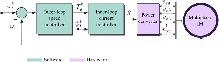
FIGURE 1. Schematic diagram of the closed-loop FOC of a multiphase IM.
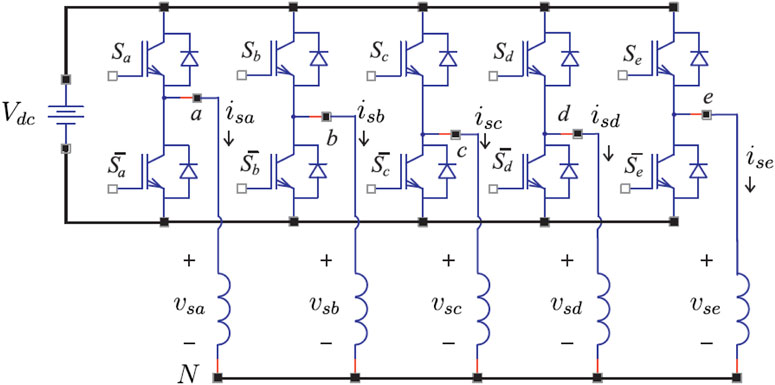
FIGURE 2. Schematic diagram of the five-phase, two-level VSC.
Applying Clarke transformation, 30 active voltage vectors and two null vectors are defined. Figure 3 shows the two-dimensional projections obtained with each of the vectors, identified with the decimal equivalent of their respective switching states
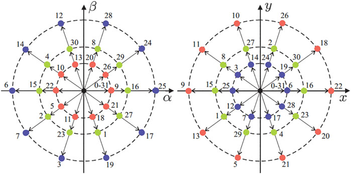
FIGURE 3. Projections of the voltage vectors in the α − β(left) and x − y(right) planes for a symmetric five-phase MI. The number that defines each voltage is the decimal equivalent of the binary number [Sa, Sb, Sc, Sd, Se].
On the other hand, this paper also addresses the asymmetrical six-phase drive with isolated neutrals as shown in the left part of the Figure 4. Other winding arrangements for the six-phase IM include the dual three-phase and the symmetrical six-phase. The main difference among them is the phase displacement between two consecutive winding (Shawier et al., 2021). Note that the asymmetrical six-phase machine is still the most frequently studied multiphase IM (Gonçalves P. et al., 2019). The choice of the asymmetrical topology was supported because this multiphase machine eliminates the sixth harmonic of the torque ripple, caused by the fifth and seventh harmonics of the stator current. Nevertheless, the utilization of a proper modulation strategy, with the adequately high switching frequency, for a six-phase VSC leads to the performance of the asymmetrical and symmetrical six-phase machines that are essentially the same (Levi et al., 2007). Moreover, the six-phase machines can be included in the so-called “multi-three-phase” drives. This topology with a higher number of phase (e.g., 6, 9, 12, 15, and so on) are gaining special consideration from the industry since they can be configured as multiple three-phase units operating in parallel. Consequently, we can use the three-phase technologies, driving to a meaningful decrease in the prices and design time (Rubino et al., 2020).
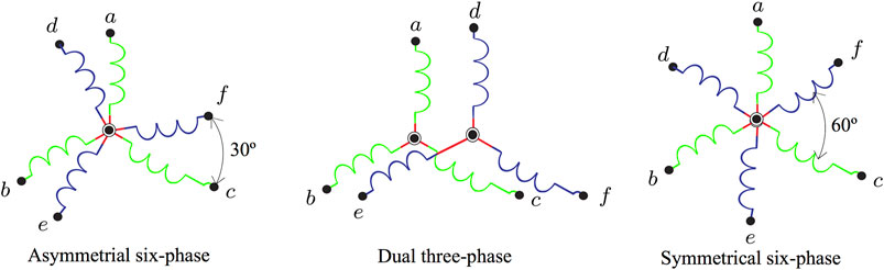
FIGURE 4. Six-phase IM winding arrangements.
Then, the VSC is now particularized to the case of the six-phase ones, as shown in the Figure 5. In the same way as the previous case, the switching function is defined as
Thereby, the voltage of phase a can be modeled as:
Then, Eq. 5 can be represented as a function of the switching state of the VSC switches (Sa, Sb, Sc, Sd, Se, Sf) and, in a similar way, the voltages vbN and vcN can be calculated, obtaining:
The same argumentation for the phases d − e − f gives rise to the following equations:
From Eqs 6–11 the phase voltages applied to the IM are represented from the potentials imposed on the stator terminals. We can model the VSC module mathematically by the matrix represented by Eq. 12, providing the values of the voltages applied to the IM stator in phase variables.
To obtain the voltage values in coordinates α − β, x − y and z1 − z2 for the configuration of a six-phase IM (n = 6) with asymmetric configuration and isolated neutrals, the following equation is used:
being θ = π/n = π/6. The VSC model is characterized by 2n = 26 = 64 possible trigger vectors (60 active and 4 null). These vectors are projected in the α − β and x − y planes as shown in the Figure 6, where all possible states are identified by two octal numbers corresponding to the binary numbers
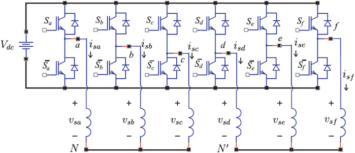
FIGURE 5. Schematic diagram of the six-phase, two-level VSC.
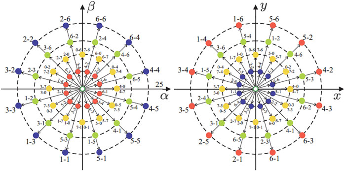
FIGURE 6. Projections of the voltage vectors in the α − β(left) and x − y(right) planes for an asymmetrical six-phase IM with isolated neutrals. The number that defines each voltage is identified by two octal numbers corresponding to the binary numbers
2.2 Five-phase and Six-phase Induction Machine State-Space Model
2.2.1 Continuous Model
We must select first properly the state variables of the IM to perform the mathematical modelling using the representation in the state-space. The stator and rotor currents in the α − β and x − y planes are the most common choices. Then, we carry out the transformations of the equations in the general frame of reference to the planes α − β and x − y. For the case of the five-phase IM fed by the VSC, the phase voltages are defined by Eq. 1 while the voltages in the α − β, x − y and z planes are represented by Eq. 2. Similarly, for the case of the asymmetrical six-phase IM, fed by the VSC, where the phase voltages are represented by Eq. 12 while the voltages in the planes α − β, x − y and z1 − z2 are represented by Eq. 13. Note that the models in state variables for the five- and six-phase IM are equal if only the α − β and x − y planes are considered, discarding the zero sequence components. The next set of equations gives the state and output equations of the linear system in continuous time:
being
The equivalent system in discrete-time is obtained using Euler’s method, being the most used method to discretize continuous systems due to its simplicity. In it, the discretization of the model can be carried out by substituting the derivative for the quotient of increments. Considering
Being the sampling time Ts, we define x[k] = X(k Ts) and taking Δt = Ts the following equation is obtained:
where x[k], that represents the states of the system, can be expressed by:
where
Finally, an estimate of the future state can be obtained as a correction of the state at the current instant from the previous equation, which results in:
Considering the stator currents in the α − β and x − y planes and the rotor currents in the α − β plane as state variables x1 = isα, x2 = isβ, x3 = isx, x4 = isy, x5 = irα and x6 = irβ, the equations that are obtained can be written as follows:
being ci for i = 1, …, 5, defined as.
being Rs the stator resistance, Rr the rotor resistance, Ls the stator inductance, Lr the rotor inductance, M the mutual inductance, Lls the stator leakage inductance, Llr the rotor leakage inductance.
The input vector corresponds to the voltages applied to the stator u1 = vsα, u2 = vsβ, u3 = vsx and u4 = vxy. Then, rewriting (20) and considering the state and output equations of the continuous time system described by Eqs 14, 15, where the input vector is
Matrices
2.2.2 Discrete Model
From the continuous-time model and using the Euler discretization method, it is possible to obtain the drive model in discrete time. The equations obtained can be written as follows:
We can represent the evolution of the state variables through the following equations derived from Eq. 25:
where
The following equations provide the rotor electrical speed (ωr) and generated torque (Te) as a function of the load torque (Tl), the number of pole pairs (P), the inertia coefficient (Jm) and the friction and the inertia coefficient (Bm):
3 Model Predictive Control for Multiphase Electric Drives
As previously introduced, MPC can be defined as an attractive regulation technique when the control designer requires a significant degree of flexibility in the control scheme (Kouro et al., 2015). The classic MPC is based on a predictive machine model, where the available switching states/voltage vectors are directly evaluated in the model system to select the optimal control action in each control cycle (as shown in Figure 7). This popular control strategy presents inherent advantages over the conventional linear current controller, such as important flexibility, including constraints and a suitable dynamic response (Vazquez et al., 2014; Young et al., 2014; Kouro et al., 2015). These interesting MPC skills particularly match with the nature of multiphase electric drives characterized by a higher number of freedom degrees (Duran and Barrero, 2016; Levi, 2016). Despite these desirable features for multiphase electric drives, conventional linear controllers have been assumed as the suitable control choice because high current quality is undoubtedly the primary goal (Lim et al., 2014). With the requirement mentioned earlier in mind, MPC has been considered by the research community of electric drives as a non-high performance regulation strategy (Lim et al., 2014). This assumption is founded on the important harmonic distortion of the phase currents when the classic MPC approach is implemented in pre-fault (Lim et al., 2014; Gonzalez-Prieto et al., 2018) and post-fault situation (Guzman et al., 2014). Nevertheless, MPC has been enhanced to exploit their advantages and solve its more inferior current quality. Some examples are the use of different discretization techniques (Miranda et al., 2009; Riveros et al., 2013; Rojas et al., 2014), the inclusion of observer methods (Rodas et al., 2016, 2017; Martin et al., 2016a) or the definition of new cost functions (Vargas et al., 2007; Duran et al., 2012; Zhou et al., 2016; Gonzalez-Prieto et al., 2019; Arahal et al., 2020; Kroneisl et al., 2020).
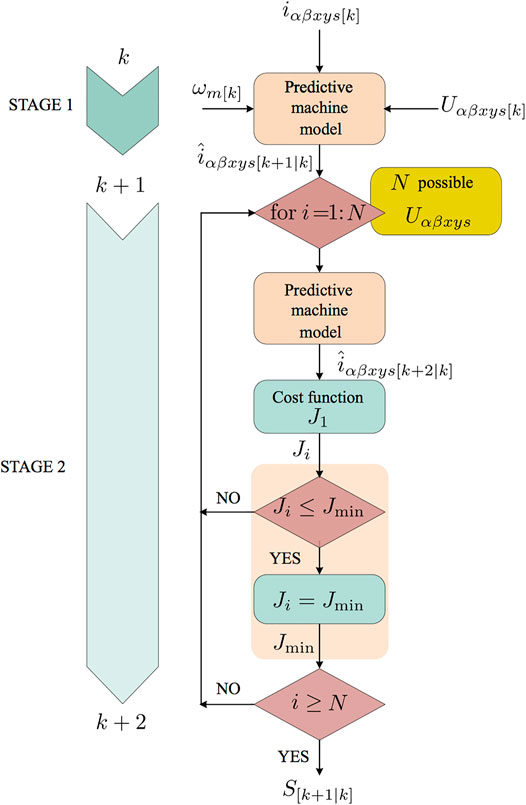
FIGURE 7. MPC flowchart for a multiphase electric drive.
However, despite these improvements incorporated into the MPC structure, the obtained phase currents still presented a higher harmonic content than in the case of control methods with conventional explicit modulation stages (Lim et al., 2014). This unfavourable scenario for classic MPC is particularly critical in multiphase drives, where several orthogonal planes need to be regulated with a single voltage vector per control cycle (Gonzalez-Prieto et al., 2018). Additionally, these secondary planes of multiphase machines are usually characterized by a lower equivalent stator impedance (Abdel-Khalik et al., 2020). Consequently, a high harmonic distortion appears in the phase currents with a low voltage injection (Gonzalez-Prieto et al., 2020; Duran et al., 2021). Fortunately, the implementation of multi-vector solutions (Gonzalez-Prieto et al., 2018; Xue et al., 2018; Luo and Liu, 2019; Ayala et al., 2020; Gonzalez-Prieto et al., 2020; Aciego et al., 2021; Ayala et al., 2021b; Duran et al., 2021; Gonçalves et al., 2021), such as synthesized or virtual voltage vectors (Gonzalez-Prieto et al., 2018; Garcia-Entrambasaguas et al., 2019; Duran et al., 2021), has permitted the minimization of the aforementioned harmonic injection thanks to the use of control actions formed by several switching states per sampling period. To take advantage of MPC features for multiphase electric drives, a significant number of researchers have promoted the development of more competitive multi-vector alternatives (Gonzalez-Prieto et al., 2018; Xue et al., 2018; Garcia-Entrambasaguas et al., 2019; Gonzalez et al., 2019; Luo and Liu, 2019; Gonzalez-Prieto et al., 2020; Aciego et al., 2021; Ayala et al., 2021b; Duran et al., 2021; Gonçalves et al., 2021), providing phase current with low harmonic content. As a consequence of the evolution of the multi-vector approach, MPC has been able to be reformulated in electric drive regulation techniques (Tenconi et al., 2018).
Based on the previous context, this section describes the structure of classic MPC approaches for multiphase electric drives and the novelties related to the improvement of this popular control strategy.
How it is Made: An MPC for Multiphase Induction Machine Drives
MPC presents a further crucial advantage, its operating principle is simple, and thanks to this issue, its structure can be described in a nutshell. So, the most famous structure of MPC is characterized by the use of an outer PI controller to regulate the mechanical speed and a two-stage inner MPC to satisfy the stator current regulation (see Figure 7, Figure 8). The available voltage vectors are employed as inputs in the prediction process to estimate the future currents. Then, these predicted currents are evaluated in a pre-defined cost function. Finally, the fitness values of the tested voltage vectors are analyzed to select the optimal control action in each control cycle (Figure 7, Figure 8).
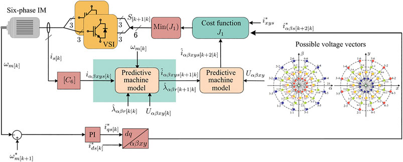
FIGURE 8. Classic MPC scheme for asymmetrical six-phase IM.
As previously exposed, the performance of MPC is highly dependent on the available voltage vectors as these are directly applied in the implicit modulator of this control scheme as control action (Gonzalez-Prieto et al., 2021). Due to this fact, the use of multi-vector solutions has especially permitted a significant improvement in the performance of this control scheme when electric drives show several orthogonal planes. Attending to the considerable role of the control actions in the field of MPC, the predictive machine model and the cost function need to be designed regarding the voltage vector employed as system inputs. Next, the first stage of implementing an MPC is to study the more appropriate procedure from the perspective of the available voltage vectors. For that reason, the following subsection describes the evolution of the control actions in MPC for multiphase electric drives.
Control Actions
Control schemes with an explicit modulation stage, as FOC with a carrier-based pulse width modulation, synthesize the reference voltage output using multiple switching states per sampling period (Bojoi et al., 2003; Che et al., 2014). This procedure favours obtaining an acceptable current quality, but the cost is a higher switching frequency (Lim et al., 2014). In MPC, the situation is the opposite since this one operates as a direct controller (Gonzalez-Prieto et al., 2021) due to the control actions are evaluated in the machine model (Gonzalez-Prieto et al., 2021). Thus, MPC is highly dependent on the available voltage vector in each electric drive (Gonzalez-Prieto et al., 2021). The previous assertion is significant when a classic MPC is implemented and a unique voltage vector is applied per control period. This MPC behaviour has been confirmed in the six-phase IM, where symmetrical and asymmetrical stator configurations possess control actions with a different location in the secondary plane (Duran et al., 2021; Gonzalez-Prieto et al., 2021). Compared to the asymmetrical arrangement, the symmetrical six-phase IMs have some active voltage vectors that do not produce x − y currents. In contrast, in the asymmetrical six-phase IM, all the active voltage vectors cause an inherent x − y injection (Duran et al., 2021). MPC can provide a suitable current quality when a single switching state is applied during the whole sampling time, thanks to the desirable location of control actions in the second plane of symmetrical six-phase IM (Gonzalez-Prieto et al., 2021). Nevertheless, the circumstance is more adverse for the asymmetrical six-phase IM since an unacceptable harmonic distortion can appear due to its inherent x − y production.
Fortunately, MPC presents an important degree of flexibility to design control actions formed by several switching states. Using this MPC feature and considering the decisive role of the secondary planes in multiphase electric drives (Abdel-Khalik et al., 2020), a significant effort of the research community has been placed in the design of multi-vector solutions to mitigate the harmonic distortion caused by these undesirable components (Gonzalez-Prieto et al., 2020). The utilization of several switching states per control cycle in MPC has also been tested for three-phase systems (Yang et al., 2021; Zhou et al., 2018). On the other hand, as previously exposed, the asymmetrical six-phase IM is one of the most studied electric drives for multiphase electric drives from this perspective. Considering the asymmetrical six-phase IM as a case study, the multi-vector approaches can be classified attending to their building procedure: offline virtual voltage vectors (Gonzalez-Prieto et al., 2018; Duran et al., 2021; Gonçalves et al., 2019c,b) and online multiple vector output (Gonzalez-Prieto et al., 2020; Aciego et al., 2021; Ayala et al., 2021b). Regardless of the assumed technique to generate these high-performance control actions, particular attention must be paid to the voltage vector location in the secondary plane due to the crucial effect of this plane in the harmonic distortion of the phase currents (Gonzalez-Prieto et al., 2018; Abdel-Khalik et al., 2020).
Analyzing the offline procedure to create the multi-vector output, (Gonzalez-Prieto et al., 2018) proposed an MPC using Virtual Voltage vectors (VVs) formed by couples of medium-large and large voltage vectors for an asymmetrical six-phase IM. These VVs ensured null x − y voltages on average during the sampling period because medium-large and large vectors with the same direction in the α − β plane have opposite direction in the x − y plane (see Figure 6). To satisfy the null-average x − y generation, the duty cycle (t1 and t2) of each voltage vector is also estimated offline, attending to their location in the secondary plane (Gonzalez-Prieto et al., 2018):
being
Concerning the mitigation of x − y components in multiphase electric drives using offline VV, the acceptable behaviour of large voltage vectors has been highlighted in the last years (Gonzalez-Prieto et al., 2020; Aciego et al., 2021; Duran et al., 2021). This set of switching states achieves the higher α − β voltage production with the lower x − y injection (Aciego et al., 2021). In the asymmetrical six-phase IM, adjacent α − β large voltage vectors are mapped in the x − y plane as small vectors shifted by 150°. Since they are not in phase opposition, the average x − y voltage cannot be fully cancelled, but it can be highly reduced. On the other hand, the transition from one large vector to the next adjacent large vector can be done by changing the state of only one VSC leg (Duran et al., 2021). Using these desirable capabilities, (Duran et al., 2021) proposed creating a set of VVs formed by an adjacent Large Voltage Vector (LVV). As a result of using these control actions, a new improvement of the phase current quality indices was reached (Duran et al., 2021). Analyzing the operating principle of MPC schemes using an offline multi-vector solution, these control strategies commonly carry out the regulation of the secondary plane in open-loop mode with the designed VVs. This ability allows the reduction of the computational burden thanks to the use of a simplified machine model and cost function (Gonzalez-Prieto et al., 2018; Duran et al., 2021). However, these offline designed multi-vector outputs are characterized by a static nature. In addition, the number of available active control actions is lower than in the case of classic MPC and then the voltage response refinement is slightly lower in the α − β plane (Gonzalez-Prieto et al., 2020; Aciego et al., 2021).
On the other hand, the online design of multi-vector voltage outputs provides the MPC with a higher dynamic nature because selecting the switching states employed to generate the voltage response is done during the control cycle (Gonzalez-Prieto et al., 2020; Aciego et al., 2021; Ayala et al., 2021b). These solutions need a higher computational cost to obtain higher flexibility in the design on the voltage output. An MPC based on the use of Dynamic Virtual Voltage vector (DVV) was developed in (Aciego et al., 2021). Three different cost functions are employed to create this multiple-voltage vector response to obtain the best couple of switching states and their respective duty cycle. This improvement in the MPC performance supposed, at the same time, a critical computational effort. Searching for better current quality for MPC, (Ayala et al., 2021b) created a voltage response using two optimal active voltage vectors and a null voltage vector per control cycle. The duty cycle of each applied switching states is estimated using its fitness value and the fitness values of the other selected voltage vectors. A branch and bound algorithm was designed to exploit the desirable performance of a large voltage vector in the asymmetrical six-phase IM. The before mentioned algorithm calculates the intelligent combination of two large voltage vectors and null voltage vectors (Gonzalez-Prieto et al., 2020). Moreover, this solution allowed the mitigation of the components to reduce active voltage injection according to the operating point. Regarding the design of online multi-vector MPC strategies, it is necessary to highlight that the predictive machine model and the quality functions need to be designed to obtain control actions with a suitable performance in all the orthogonal planes. For this reason, the computational cost of these MPC schemes is usually higher (Gonzalez-Prieto et al., 2020).
Predictive Machine Model
The most accepted MPC approach (Duran and Barrero, 2016) is based on using a two-stage predictive process to estimate the future currents using the available control actions. This two-step forward prediction algorithm compensates for the time delay introduced by sampling and computation time (Cortes et al., 2012; Young et al., 2014). The estimation of the currents in the predictive process is carried out in a discretized IM model (Barrero et al., 2009). The measurement/predictive variables and the applied/available control actions are established as the system inputs. Figure 8 shows the relationship between the variable and the discretized IM model in the different stages of the prediction process.
Focusing on IM model building, different discretization methods, such as Euler and Cayley Hamilton (Miranda et al., 2009; Rojas et al., 2014), have been employed to develop a sample-data model of the electric IM equations. Both methods present a satisfactory approximation of the discretization conditions that are not too restrictive. Nevertheless, the Cayley Hamilton approach is recommended in (Rojas et al., 2014) because this one reaches an accurate approximation, particularly compared to the usual Euler method (Miranda et al., 2009; Riveros et al., 2013). As expected, the performance of the discretized IM model also depends on the proper estimation of the electric parameter values. The sensitivity of predictive controllers to parameter variation has recently been analyzed (Martin et al., 2017). Unfortunately, the reasonable estimation of the electric parameters can be defined as a necessary but not sufficient condition as some may change during the drive operating. This undesirable scenario can be mitigated by including exogenous variables in the IM model (Bermudez et al., 2021) or the use of observer methods as in (Xia et al., 2012), where a Luenberger Observer (LO) is implemented.
Additionally, observer methods can be employed to estimate non-measured variables used in the predictive machine model as inputs (see Figure 9). In this regard, the control designer can know the rotor values for which sensors are not available (Martin et al., 2016b). The addition of these observation techniques allows a better approximation of the non-measurable variables involved in the prediction process. Nevertheless, due to the implementation of these exciting tools, the computational cost of MPC increases. We can classify the observer methods into reduced-order and full-order observers (Jansen and Lorenz, 1994; Davari et al., 2012). Using the reducer-order form, the rotor components can be obtained with the measurements of speed and stator currents (Davari et al., 2012). On the other hand, full-order observers provide the stator and rotor variable estimation with speed and stator voltages/currents measurements. The estimation of rotor variables using Kalman Filter (KF) in MPC for a six-phase IM was introduced theoretically in (Rodas et al., 2013a) and compared with LO in (Rodas et al., 2013b). Then, the experimental validation and the impact of the online estimation of rotor variables in MPC have been studied in (Rodas et al., 2016), where MPC with an observer clearly outperforms the classic MPC approach, presenting some benefits such as better current tracking performance, less harmonic content, and lower switching losses. Speaking about the benefits obtained with the inclusion of a method observer in the prediction process, the role of close-loop observers, as such KF or LO, can be highlighted thanks to the improvement provided with these methods in the regulation of the stator currents of multiphase electric drives (Rodas et al., 2017).
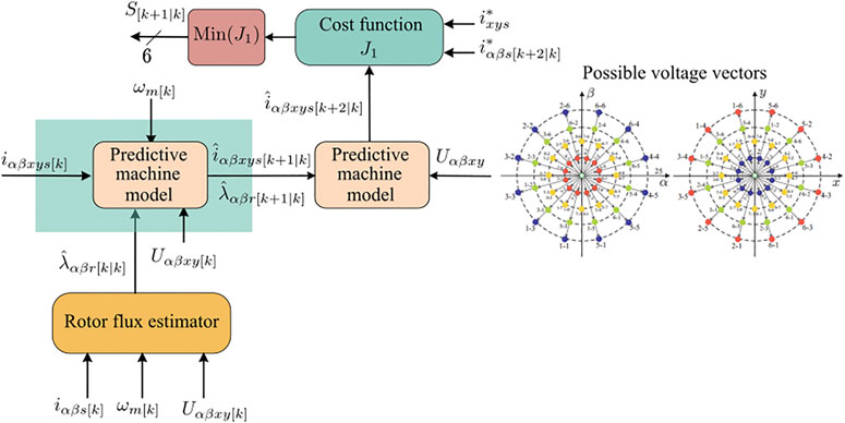
FIGURE 9. Addition of a full-order rotor flux observer in a MPC scheme for asymmetrical six-phase IM fed by two Voltage Source Inverters (VSIs).
Due to the applied/available voltage vectors are evaluated in the predictive machine model, this one should be defined according to the designed control actions. This assumption can be explained using the case of an asymmetrical six-phase IM where all the active control actions also generate an inherent x − y injection. For instance, the discretized predictive machine model needs to include α − β and x − y components if the secondary plane cannot be regulated in open-loop mode with the usage of the available control actions:
where
The matrices
On the other hand, if the secondary components are directly regulated in open-loop mode with the use of the several switching states per control cycle, for example, using offline virtual voltage vectors (Gonzalez-Prieto et al., 2018; Duran et al., 2021), then the discretized IM model can be simplified as follows:
These reduced
Regarding the employed discretized IM model, once the predicted currents are obtained, the goodness of each one is confirmed in the proposed cost function.
Cost Function
As previously exposed, the voltage response with the better fitness value is selected as the applied control action. For that purpose, a predefined cost function needs to be designed to study the capability of each possible voltage output to satisfy the reference requirements. It is common to compare the reference currents
being
The k1 and k2 coefficients are the weighting factors for α − β and x − y planes, respectively. The value of these coefficients can be established according to the operating electric drive requirements. This procedure is typically a trade-off between flux/torque production and a low harmonic current injection. Speed track is the main goal, but the obtaining of satisfactory current quality cannot be obviated. The x − y currents are only a source of copper losses with no impact on the flux/torque production when distributed-winding IMs are employed. Hence, the reference value of these currents is usually set to zero, and the selection of k1 and k2 coefficients is a trade-off between flux/torque regulation (k1) and efficiency/distortion (k2). It must be highlighted, however, that despite the possibility to vary the importance that is paid to α − β and x − y planes, the selection of a single switching state (Figure 6) implies that it is impossible to satisfy the needs of both planes simultaneously in a control cycle (Arahal et al., 2018; Fretes et al., 2021).
Though, the previous cost function can be simplified when the secondary components are regulated in open-loop mode with the designed control actions:
This cost function allows the reduction of the computational cost and the tasks related to the definition of the appropriate values of the weighting factors for each electric drive. However, this strategy could present a more inferior capability to cancel the effect of the non-linearities of the VSC when high switching frequencies are employed (Jones et al., 2009).
The use of the cost function is not only restricted to provide satisfactory current tracking. In fact, the control designer can exploit the flexibility of MPC to include additional coefficients in the cost function to fulfil other requirements (Vargas et al., 2007; Duran et al., 2012; Zhou et al., 2016; Gonzalez-Prieto et al., 2019; Arahal et al., 2020; Kroneisl et al., 2020). For example, several works have employed the quality function to reduce the switching frequency (Vargas et al., 2007; Gonzalez-Prieto et al., 2019). (Vargas et al., 2007) proposed the reduction of this operating parameter in a three-level VSC thanks to the inclusion of specific terms related to this operating parameter in the cost function. Following the same approach, (Gonzalez-Prieto et al., 2019) developed an MPC with a trade-off between current quality and switching frequency for a nine-phase electric drive. The minimization of the common-mode voltage has been explored in (Duran et al., 2012) with the use of a predefined quality function. Regardless of the new variable incorporated in the cost function, this task is carried out in a simple manner due to the high flexibility to include constraints in MPC.
4 Discrete-Time Sliding-Mode-Based Strategies for Multiphase Induction Machine
Multiphase IM drives are coupled nonlinear systems associated with uncertain dynamics and external matched disturbances. The α − β and the x − y stator currents are controlled via a power electronic converter with a discrete-time nature. For these reasons, the control paradigm calls for advanced robust discrete-time nonlinear techniques. Hence, the subsequent parts will present a noteworthy literature review on discrete-time nonlinear control approaches designed for multiphase IM drives. Advanced discrete-time nonlinear methods have been widely studied, designed and implemented in real-time on multiphase IM drives. Some examples include SMC (Echeikh et al., 2018; Kali et al., 2019c; Zaidi et al., 2019; Kali et al., 2020b,c), fuzzy logic (Fnaiech et al., 2010; Liu et al., 2017; Bessaad et al., 2019; Rinkeviciene et al., 2021) backstepping (Kali et al., 2019b; Morawiec et al., 2020; Mossa and Echeikh, 2021) and adaptive control (Guo and Parsa, 2012; Wang W. et al., 2018). Apart from the above-mentioned conventional techniques, enhanced methods based on methods combinations and/or augmented theory will be discussed.
4.1 Conventional Discrete-Time Sliding Mode Control
This section introduces the reader to the basic notions of conventional DSMC. This latter is one of the most interesting nonlinear techniques used in several control system problems. The basics of SMC is born in the former Soviet Union in the early 50s, led by V. I. Utkin and S. V. Emelyanov (Utkin, 1977). Figure 10 gives a graphical explanation of SMC, which uses discontinuous control input signals to force the system’s states to converge in a finite time to the user-designed sliding surface (see Figure 10A). This latter is designed to ensure during the sliding phase (see Figure 10C) an exponential (conventional linear surface) or finite-time (terminal sliding surface) convergence. Moreover, during the sliding phase, the system trajectories evolve in a strict neighbourhood’s chosen surface. SMC has received enormous attention since it guarantees insensitivity against matched disturbances and uncertainties. This insensitivity is reached by selecting large suitable reaching control law gains. However, this leads to high-frequency switching signals that cause the major drawback of SMC, the well-known Chattering Figure 10B (Fridman, 2001; Boiko and Fridman, 2005). This undesirable phenomenon negatively impacts the controlled system since it can damage the actuators, produce a high energy loss, and lead to instability. For these reasons, the real-time implementation of SMC is limited.
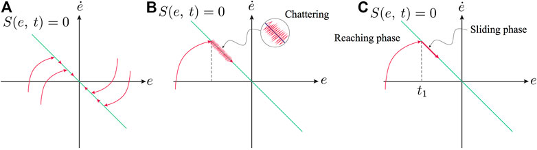
FIGURE 10. Graphic interpretation of the SMC. (A) Reaching phase. (B) Chattering (C) Sliding phase.
In literature, many published papers attempted to solve the problem mentioned above of Chattering. The earlier solution proposed the SMC-based boundary layers (Young et al., 1999) that consists of using linear reaching laws instead of the discontinuous ones. This proposition succeeded to reduce Chattering. However, both the invariance and the finite-time reaching properties of SMC are lost. Hence, the method is no more robust. Another well-known proposition consists of the observer-based SMC (Drakunov and Utkin, 1995; Yan and Edwards, 2007). This method allows smaller choice for the switching gains. However, the tracking might not be accurate if no exact estimation is obtained. Other works combined the conventional SMC with intelligent techniques (Fnaiech et al., 2010). Accurate uncertainties estimation can be obtained via these intelligent techniques. However, the real-time implementation is limited because of the introduced complex computations. In (Levant, 2003; Kali et al., 2017; Kali et al., 2018c), the high-order SMC where the discontinuous control actions are involved in the higher control derivatives, which implies that the control signal that fed into the system becomes continuous, has been proposed. Some published papers present a DSMC (Utkin, 1994; Su et al., 2000; Li et al., 2014) motivated by the fact that the switching frequencies are limited in real life and that the real-time implementation is computer-based.
For the above-mentioned reasons, researchers began to study SMC in discrete-time form. On the one hand, some works proposed reaching laws based on DSMC using the conventional known and new discrete switching reaching laws that use the signum function. On the other hand, other works proposed equivalent DSMC-based on the discrete-time models. In both types of works, the control objective is to ensure a quasi-sliding mode motion. In other words, the objective is to keep the system states in a very small boundary layer. In this part, the design of the conventional DSMC is described briefly. To that end, consider the dynamics of a six-phase IM given by Eqs 28, 29, the design procedure consists of the two following steps:
• Design the conventional discrete-time sliding functions for the α − β and the x − y planes as follows:
where
• For both planes, the computed discrete-time controller should verify the following conditions:
The above conditions can be satisfied by choosing the following reaching law:
where the elements of the
and the sign is defined by:
Then, resolving Eq 48, 49 using the nominal model (i.e., without taking into consideration the rotor currents) gives the DSMC law for the stator currents as follows:
Finally, the control actions represented by Eqs 49, 50 are discrete signals that are sent to a modulator as shown in Figure 11.
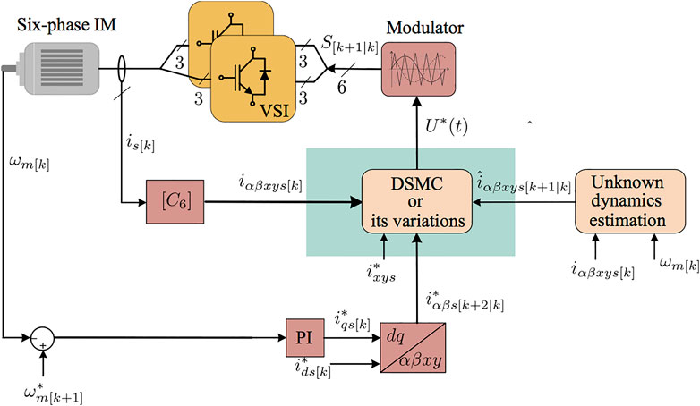
FIGURE 11. Classic SMC scheme for asymmetrical six-phase IM fed by two Voltage Source Inverters (VSI).
4.2 Time-Delay Estimator-Based Discrete-Time Sliding Mode Control
The tracking performance using the above DSMC might not be satisfactory. The reason behind this is that the dynamics related to the unmeasurable rotor currents
In the continuous-time domain, an interesting TDE-based conventional SMC for a class of second-order nonlinear systems subject to unknown dynamics and unexpected disturbances has been proposed (Kali et al., 2015; Kali et al., 2018a). The idea here consists of adding in the DSMC law the estimated uncertainties, which guarantees stability while choosing small switching gains. This latter is assumed to vary slowly during a very little time, approximated using delayed measurable states and delayed control signals. It has been demonstrated through practical works on seven degrees of freedom robot arm that the method is successful and reduces the Chattering and has also been implemented on several other robotic systems (Wang et al., 2016; Lee et al., 2017; Wang et al., 2020).
Inspired by the works mentioned above, a robust TDE-based DSMC for the inner stator currents control loop has been proposed, developed and tested in real-time on an asymmetrical six-phase IM in the presence of uncertainties in (Kali et al., 2019a). Unlike the conventional DSMC, this method maintains the inherent properties of sliding motion. Another novelty in this work is that the time required for the systems states to converge to the designed surfaces is computed. The designed discrete method can be easily extended for all discrete linear and nonlinear systems and all symmetrical and asymmetrical multiphase drives. Figure 11 shows the closed-loop FOC with inner current loop based on SMC.
As said before, the only difference in the design procedure consists of incorporating the approximated uncertain dynamics and unmeasurable rotor currents computed using discrete TDE as follows:
Hence, adding the above approximation to the conventional DSMC gives the proposed TDE-based DSMC for the stator currents in the α − β and the x − y planes as follows:
where
The computed TDE-based DSMC in Eqs 52, 53 ensures the existence of a quasi sliding mode if
In addition, each stator current will reach its corresponding known desired current within at most kreach + 1 steps defined by:
Proposition 1.To enhance the effectiveness of the proposed TDE-based DSMC and to reduce the quasi sliding mode band the Chattering, the Exponential Reaching Law (ERL) can be used in discrete form instead of the conventional discrete reaching law. Hence, a robust nonlinear TDE-based DSMC with ERL (Kali et al., 2019d) can be obtained for the α − β and the x − y stator currents as follows:
where
beingɛ•s ∈ (0, 1) andη•s > 0 for • = {α, β, x, y}.
Remark 1.The ERL is a kind of adaptive control gains since this latter varies in terms of the tracking error values. Indeed, the values of the switching gains increase or decrease in proportion to the absolute value of the designed sliding surface, such as a fast reaching occurs for large values, and a low control effort is guaranteed during the sliding phase. In other words, E•s(S•s[k]) in Eq. 60 converges to ɛ•s when the corresponding stator current tracking error has a significant value. At the same time, it converges to 1 when the corresponding stator current tracking error reaches zero. Moreover, TDE-based DSMC with ERL can ensure faster convergence than TDE-based conventional DSMC while reducing the Chattering since smaller switching gains can achieve stability.
4.3 Discrete-Time Super-twisting Algorithm Control
High-order sliding mode is considered to be one of the most effective methods that solve the problem of Chattering (Levant, 2010). This method has been extensively used since it keeps the insensitivity property of conventional SMC and guarantees a higher tracking precision. The order in this approach depends on the relative degree of the controlled system and the designed sliding function. Actually, the most developed one is the second-order sliding mode (Pisano, 2012; Kali et al., 2017; Shi et al., 2019). It consists of computing the first time derivative of the control input signal in terms of the switching action, which become continuous once integrated. Even if several reaching laws and algorithms have been proposed to enhance the convergence speed and reduce the Chattering, it does not lack problems as all developed nonlinear techniques. The main problem of the second-order SMC lies in the difficulty of its real-time implementation since it requires usually unavailable system’s information. This limitation entails the need to integrate an observer in the loop, which makes the problem more complex.
A successful continuous second-order sliding mode algorithm called super-twisting has received massive attention in the past few years as it solves the problem mentioned above. In addition, it ensures insensitivity to a more significant number of matched uncertainties. The closed-loop stability-based Lyapunov, the problem of robustness against uncertainties and convergence time estimation issues have been widely discussed in the literature (Moreno, 2009; Moreno and Osorio, 2012; Castillo et al., 2018). Otherwise, several works attempted to enhance this algorithm, such as adaptive super-twisting control (Plestan and Chriette, 2012; Borlaug et al., 2020; Obeid et al., 2020), variable gains super-twisting (Dávila et al., 2010; Gonzalez et al., 2012; Vidal et al., 2017) and TDE-based optimal super-twisting (Kali et al., 2018b; Wang Y. et al., 2018). This latter is easy to implement and gives good results on a redundant robot arm. However, for the particular case of a multiphase machine where the power electronic converter has a discrete nature, a controller-based discrete mode is required, while the few existing works use an emulation design. This latter consists of a discretization that is usually based on the explicit Euler method. In super-twisting, this method requires selecting significant gains that might lead to undesirable high control effort. In (Kali et al., 2020a), an implicit TDE-based DSTA has been developed for an asymmetrical six-phase IM. The few developed implicit DSTA has been all used as an observer, which changes the stability analysis. However, the approximated unknown dynamics obtained using the TDE method make it possible to ensure convergence, and this even with small control gains.
In the following, a brief description of the design steps:
• Estimate the unknown dynamics (i.e., unmeasurable rotor currents and unexpected perturbations) using the discrete TDE as in Eq. 51.
• Design the sliding surfaces for the α − β and the x − y stator currents to be the error between the measured currents and the desired ones as in Eqs 42, 43.
• Compute the discrete control law for the α − β and the x − y stator currents by resolving the following DSTA formulas:
where the elements of the diagonal matrices
The gain of the diagonal matrices
Notice that the implicit TDE-based DSTA guarantees the convergence of the stator currents tracking to a ball in the neighbour of the equilibrium point.
Another significant drawback of SM theory lies in choosing the switching surface since the obtained performance depends on it during the sliding phase. Indeed, undesirable performance should be expected if the linear switching surface is not well designed. Thus, since the linear switching surface guarantees an asymptotic convergence and not a finite-time one, its design is a complicated task (Tokat et al., 2002, 2003). Nevertheless, a Terminal SMC (TSMC) has been proposed (Mu and He, 2018; Kali et al., 2021) in the literature. This method is based on the classical SMC technique but uses a nonlinear sliding surface. This latter allows a finite-time convergence and ameliorates the system’s convergence properties during the sliding phase. For this reason, the presented TDE-based DSTA had been enhanced in (Kali et al., 2021b).
Proposition 2An improved TDE-based DSTA has been developed by using a discrete-time terminal sliding surface to enhance convergence speed and ensure robustness against matched uncertainties and non-repeatable parameter variations. This latter usually occurs in electrical motors because of the heat of the components. The proposed TDE-based Discrete Terminal Super-Twisting Algorithm (DTSTA) (Kali et al., 2021b) has been implemented successfully on a real six-phase IM. The control inputs can be obtained using the algorithms in Eqs 63, 64 for the α − β and the x − y stator currents as follows:
where
being
withγ• ∈ (0, 1) for • = {α, β, x, y}.
5 Experimental Assessment
To analyze first some of the most recent developments of MPC, a 2 kW six-phase IM with a nominal mechanical speed of 3 000 rpm test-bench is used. Readers can find more details about the system and the parameters of the IM in (Ayala et al., 2021b). Four model predictive current control structures are compared, namely classic MPC (Rodas et al., 2016), modulated-MPC (M2PC) (Gonzalez et al., 2019), MPC with Virtual Vector (VV-MPC) (Gonzalez-Prieto et al., 2018) and a Novel Modulated MPC (N-M2PC) (Ayala et al., 2021b). Because of its flexibility in controlling objectives and fast dynamic response, MPC is still considered an exciting alternative to linear control structures for multiphase IMs. However, as Figure 12A shows, the regulation of the secondary x − y is poor with a high current ripple due to the use of single control action during the whole sample period. Instead of discarding this controller due to its high harmonic distortion, several solutions based on enhancing its implicit modulators, such as multi-vector solutions as control actions, have been proposed. We can see from Figure 12B–D three solutions that considerably reduce the x − y currents at expense of higher current ripple in α − β currents. It is worth mentioning that the dynamic behaviour remains visually the same for all MPC techniques demonstrated by Figure 12E–H. We can comprehend the latter by Figure 12I,J, extracted from (Rivas-Martinez et al., 2021) performed an exhaustive comparison between classic MPC and M2PC using statistical analysis. Stability analysis of MPC for a six-phase IM was recently analyzed in (Ayala et al., 2021a). Figure 12K,L show the trend charts of the maximum stable rotor speeds, which is defined as the rotor speed where the stator currents controller can no longer be appropriately regulated as more significant oscillations appear, destabilizing the system and average switching frequencies for classic MPC, M2PC and N-M2PC at different sampling frequencies. It is worth knowing the limits of stability regarding rotor speed and sampling frequencies for other modulated MPC to understand these critical operating points and then apply techniques with the lowest possible sampling frequency, reducing the switching losses in power converters.
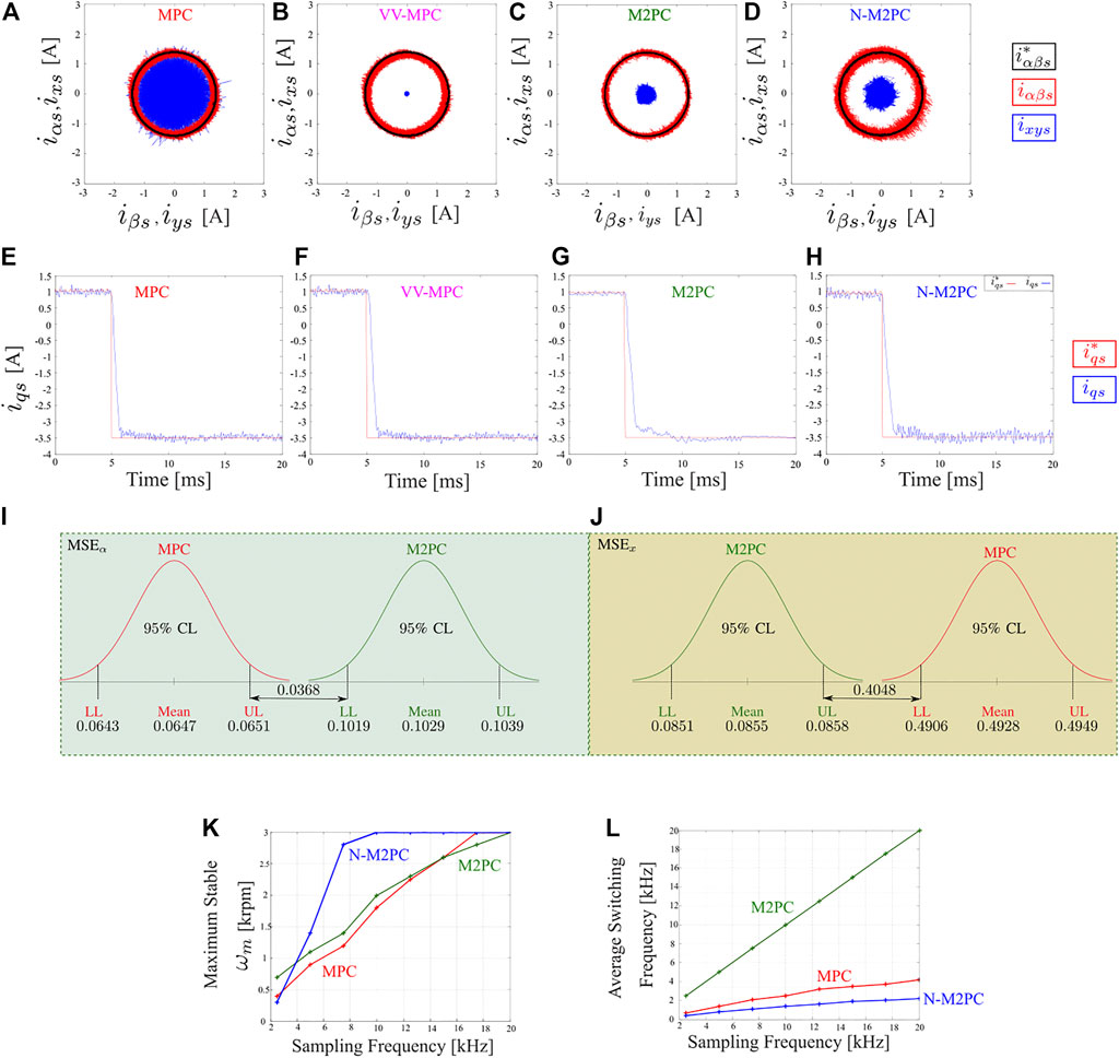
FIGURE 12. Steady-state analysis: stator α − β and x − y currents in an asymmetrical six-phase IM fed by a dual three-phase VSC (A) classic MPC (Rodas et al., 2016), (B) Modulated-MPC (M2PC) (Gonzalez et al., 2019), (C) MPC with virtual vector (VV-MPC) (Gonzalez-Prieto et al., 2018) and (D) a Novel Modulated MPC (N-M2PC) (Ayala et al., 2021b). Transient-analysis: stator q-axis current: (E) classic MPC, (F) M2PC, (G) MPC-VV and (H) N-M2PC. Statistical comparison between MPC and M2PC (I)α-axis and (J)x-axis (Rivas-Martinez et al., 2021). Trend chart of classic MPC, M2PC and N-M2PC regarding different sampling frequencies and: (K) rotor mechanical speed; (L) average switching frequency (Ayala et al., 2021a).
Then, as previously exposed, the usage of multi-vector solutions has permitted the mitigation of the harmonic content of phase currents when MPC strategies are employed to regulate multiphase electric drives. Figure 13 summarizes the evolution of the current quality improvement in an asymmetrical six-phase IM using diverse MPC techniques (Gonzalez-Prieto et al., 2018; Aciego et al., 2021; Duran et al., 2021). For that purpose, the phase currents of four published MPC schemes have been tested using a paired evaluation:
• Comparation 1: classical MPC, Figure 13A vs. MPC using VVs (VV-MPC) Figure 13B (Gonzalez-Prieto et al., 2018).
• Comparation 2: VV-MPC, Figure 13C vs. MPC using LVVs (LVV-MPC) Figure 13D (Duran et al., 2021).
• Comparation 3:VV-MPC, Figure 13E vs. MPC using DVV (DVV-MPC), Figure 13F (Aciego et al., 2021).
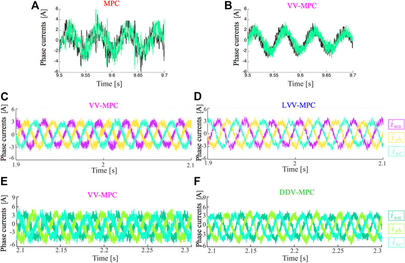
FIGURE 13. Phase currents in an asymmetrical six-phase IM fed by a dual three-phase VSC. From top to bottom: (A) classic MPC vs. (B) VV-MPC(Gonzalez-Prieto et al., 2018), (C) VV-MPC vs. (D) LVV-MPC (Duran et al., 2021) and (E) VV-MPC vs. (F) DVV-MPC (Aciego et al., 2021).
In Figure 13, the phase currents show a significant improvement when several switching state per sampling period are employed as multi-vector control action. In fact, Figure 13A illustrates the limited capability of MPC to reduce harmonic distortion if a single switching states is applied during the entire control cycle. On the other hand, the combination of large voltage vectors to generate multi-vector control actions presents an enhanced harmonic distortion (see Figure 13C,D) due to their reduced contribution in the secondary plane. This result is also obtained when the virtual voltage vectors are generated using an online procedure (Aciego et al., 2021), as shown in Figure 13E,F. Nevertheless, the use of an online method implies a higher computational burden than in the case of LVV-MPC. Therefore the goodness of this control scheme can be highlighted over the skills of the compared MPC techniques.
Finally, we exhibit the experimental performance of SMC using the same experimental test-bench as the one obtained used for the results presented in Figure 4. In this case, we show in Figure 14A–D the steady-state performance of four SM-based current controllers explained in the previous section. As expected, Figure 14A shows the higher Chattering of classic SMC. We can note that DSMC-ERL (Kali et al., 2019d) shows better performance than the rest in this operating point, while DTSTA (Kali et al., 2021b) has also considerably ripple in some parts. Figure 14E compares DSMC with DSTA using the mean square error of the stator current tracking in α − β and x − y planes. We can compute the improvement introduced by DSTA up to 79% (Kali et al., 2020a).
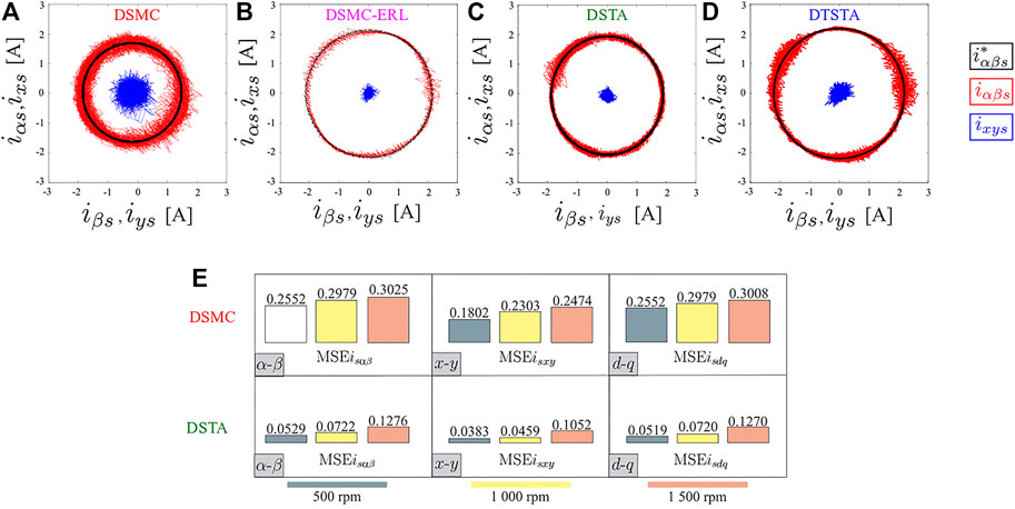
FIGURE 14. Steady-state analysis: stator α − β and x − y currents in an asymmetrical six-phase IM fed by a dual three-phase VSC (A) Discrete-time Sliding Mode Control (DSMC) (Kali et al., 2019a), (B) DSMC with Exponential Reaching Law (DSMC-ERL) (Kali et al., 2019d), (C) Discrete-time Super-Twisting Algorithm (DSTA) (Kali et al., 2020a) and (D) Discrete-time Terminal Super-Twisting Algorithm (DTSTA) (Kali et al., 2021b). (E) Comparative between DSMC and DSTA using Mean Squared Error (MSE) as performance parameter (Kali et al., 2020a).
6 Conclusion
The paper presents a review of the foremost model predictive and sliding mode current control algorithm applied to the most popular multiphase induction machine topologies, i.e., five-phase and six-phase. A comprehensive description of model predictive current control and its variants has been provided. On the other hand, the sliding mode control approach has also been included in this paper. Featured experimental case studies are provided to compare the multiple control schemes.
Focusing on the case of MPC, the implementation of multi-vector solutions has played an essential role in improving the phase current quality when an MPC strategy is employed to regulate a multiphase electric drive. These control actions allow, at the same time, the tracking of the flux/torque requirement and the mitigation of the harmonic content caused by the secondary components, avoiding the limitation of classical MPC where a single switching state is applied during the whole of the sampling period. The new generation of MPC strategies simultaneously provides to the control designer the conventional MPC advantages, such as high flexibility and fast dynamic response, and a reduced current harmonic injection. The future trend of MPC can be related to the use of more competitive control actions. For instance, by increasing the number of switching states employed to create the multi-vector outputs, the development of nonlinear models to improve the accuracy of the machine model when the sampling period is too high, or the use of integral terms to reduce the steady-state errors.
Despite the improvements obtained using SMC, the Chattering issue should be carefully addressed to mitigate the impact of the switching function. This can be done using higher order SMC or a model based SMC approach. In addition, the convergence time of the SMC approach can be fixed. For this purpose, a terminal SMC approach can be used in the future to impose a desired convergence time. Future works may include the real-time implementation of SMC techniques like power SM, terminal SM, higher-order SM, fractional control, synergetic control for multiphase machines.
It is worth mentioning some crucial differences between MPC and SMC. While MPC performance is better as the sampling frequency becomes higher, it is the opposite in SMC. In SMC, the worse performance is due to the sign function at high frequency; the Chattering becomes more aggressive. However, in MPC, the performance is better because the predictions are faster. Moreover, MPC has an intrinsic modulator while SMC-based controllers need a modulation stage like linear PI controllers. MPC is also intuitive, and constraints are easy to include in the cost function. However, SMC has a more complex mathematical model that may not be straightforward.
Author Contributions
JR conceived the idea for this survey paper. JR, IG-P, and YK were responsible for the main writing of the paper, while MS and JD-G were responsible for revising the manuscript. All authors contributed to the article and approved the submitted version.
Conflict of Interest
The authors declare that the research was conducted in the absence of any commercial or financial relationships that could be construed as a potential conflict of interest.
Publisher’s Note
All claims expressed in this article are solely those of the authors and do not necessarily represent those of their affiliated organizations, or those of the publisher, the editors and the reviewers. Any product that may be evaluated in this article, or claim that may be made by its manufacturer, is not guaranteed or endorsed by the publisher.
Acknowledgments
JR acknowledges the support of CONACYT through its PRONII program. This work was supported in part by the Spanish State Research Agency (AEI) under project PID2019-105612RB-I00/AEI/10.13039/501100011033.
References
Abdel-Khalik, A. S., Abdel-Majeed, M. S., and Ahmed, S. (2020). Effect of Winding Configuration on Six-phase Induction Machine Parameters and Performance. IEEE Access 8, 223009–223020. doi:10.1109/ACCESS.2020.3044025
Aciego, J. J., Gonzalez Prieto, I., Duran, M. J., Bermudez, M., and Salas-Biedma, P. (2021). Model Predictive Control Based on Dynamic Voltage Vectors for Six-phase Induction Machines. IEEE J. Emerg. Sel. Top. Power Electron. 9, 2710–2722. doi:10.1109/JESTPE.2020.2977144
Arahal, M. R., Barrero, F., Durán, M. J., Ortega, M. G., and Martín, C. (2018). Trade-offs Analysis in Predictive Current Control of Multi-phase Induction Machines. Control. Eng. Pract. 81, 105–113. doi:10.1016/j.conengprac.2018.09.012
Arahal, M. R., Martín, C., Kowal, A., Castilla, M., and Barrero, F. (2020). Cost Function Optimization for Predictive Control of a Five‐phase IM Drive. Optim Control. Appl. Meth 41, 84–93. doi:10.1002/oca.2499
Ayala, M., Doval-Gandoy, J., Gonzalez, O., Rodas, J., Gregor, R., and Rivera, M. (2021a). Experimental Stability Study of Modulated Model Predictive Current Controllers Applied to Six-phase Induction Motor Drives. IEEE Trans. Power Electron. 36, 13275–13284. doi:10.1109/TPEL.2021.3081347
Ayala, M., Doval-Gandoy, J., Rodas, J., Gonzalez, O., and Gregor, R. (2020). Current Control Designed with Model Based Predictive Control for Six-phase Motor Drives. ISA Trans. 98, 496–504. doi:10.1016/j.isatra.2019.08.052
Ayala, M., Doval-Gandoy, J., Rodas, J., Gonzalez, O., Gregor, R., and Rivera, M. (2021b). A Novel Modulated Model Predictive Control Applied to Six-phase Induction Motor Drives. IEEE Trans. Ind. Electron. 68, 3672–3682. doi:10.1109/TIE.2020.2984425
Barrero, F., Arahal, M. R., Gregor, R., Toral, S., and Duran, M. J. (2009). A Proof of Concept Study of Predictive Current Control for VSI-Driven Asymmetrical Dual Three-phase Ac Machines. IEEE Trans. Ind. Electron. 56, 1937–1954. doi:10.1109/TIE.2008.2011604
Barrero, F., and Duran, M. J. (2016). Recent Advances in the Design, Modeling, and Control of Multiphase Machines-Part I. IEEE Trans. Ind. Electron. 63, 449–458. doi:10.1109/TIE.2015.2447733
Bermudez, M., Arahal, M. R., Duran, M. J., and Gonzalez-Prieto, I. (2021). Model Predictive Control of Six-phase Electric Drives Including Arx Disturbance Estimator. IEEE Trans. Ind. Electron. 68, 81–91. doi:10.1109/tie.2019.2962477
Bessaad, T., Taleb, R., Chabni, F., and Iqbal, A. (2019). Fuzzy Adaptive Control of a Multimachine System with Single Inverter Supply. Int. Trans. Electr. Energ. Syst. 29, e12070. doi:10.1002/2050-7038.12070.E12070ITEES-18-1037.R2
Boiko, I., and Fridman, L. (2005). Analysis of Chattering in Continuous Sliding-Mode Controllers. IEEE Trans. Automat. Contr. 50, 1442–1446. doi:10.1109/tac.2005.854655
Bojoi, R., Lazzari, M., Profumo, F., and Tenconi, A. (2003). Digital Field-Oriented Control for Dual Three-phase Induction Motor Drives. IEEE Trans. Ind. Applicat. 39, 752–760. doi:10.1109/TIA.2003.811790
Borlaug, I.-L. G., Pettersen, K. Y., and Gravdahl, J. T. (2020). “The Generalized Super-twisting Algorithm with Adaptive Gains,” in 2020 European Control Conference (ECC) (IEEE), 1624–1631. doi:10.23919/ECC51009.2020.9143617
Castillo, I., Fridman, L., and Moreno, J. A. (2018). Super-twisting Algorithm in Presence of Time and State Dependent Perturbations. Int. J. Control. 91, 2535–2548. doi:10.1080/00207179.2016.1269952
Che, H. S., Levi, E., Jones, M., Hew, W.-P., and Rahim, N. A. (2014). Current Control Methods for an Asymmetrical Six-phase Induction Motor Drive. IEEE Trans. Power Electron. 29, 407–417. doi:10.1109/TPEL.2013.2248170
Cortes, P., Rodriguez, J., Silva, C., and Flores, A. (2012). Delay Compensation in Model Predictive Current Control of a Three-phase Inverter. IEEE Trans. Ind. Electron. 59, 1323–1325. doi:10.1109/TIE.2011.2157284
Davari, S. A., Khaburi, D. A., Wang, F., and Kennel, R. M. (2012). Using Full Order and Reduced Order Observers for Robust Sensorless Predictive Torque Control of Induction Motors. IEEE Trans. Power Electron. 27, 3424–3433. doi:10.1109/tpel.2011.2179812
Dávila, A., Moreno, J. A., and Fridman, L. (2010). “Variable Gains Super-twisting Algorithm: A Lyapunov Based Design,” in Proceedings of the 2010 American Control Conference (IEEE), 968–973. doi:10.1109/ACC.2010.5530461
Drakunov, S., and Utkin, V. (1995). “Sliding Mode Observers. Tutorial,” in 34th IEEE Conference on Decision and Control (IEEE), 3376–3378. doi:10.1109/CDC.1995.479009
Duran, M. J., and Barrero, F. (2016). Recent Advances in the Design, Modeling, and Control of Multiphase Machines-Part II. IEEE Trans. Ind. Electron. 63, 459–468. doi:10.1109/TIE.2015.2448211
Durán, M. J., Gonzalez-Prieto, I., and Gonzalez-Prieto, A. (2021). Large Virtual Voltage Vectors for Direct Controllers in Six-phase Electric Drives. Int. J. Electr. Power Energ. Syst. 125, 106425. doi:10.1016/j.ijepes.2020.106425
Duran, M. J., Riveros, J. A., Barrero, F., Guzman, H., and Prieto, J. (2012). Reduction of Common-Mode Voltage in Five-phase Induction Motor Drives Using Predictive Control Techniques. IEEE Trans. Ind. Applicat. 48, 2059–2067. doi:10.1109/TIA.2012.2226221
Echeikh, H., Trabelsi, R., Iqbal, A., and Mimouni, M. F. (2018). Real Time Implementation of Indirect Rotor Flux Oriented Control of a Five-phase Induction Motor with Novel Rotor Resistance Adaption Using Sliding Mode Observer. J. Franklin Inst. 355, 2112–2141. doi:10.1016/j.jfranklin.2017.12.022
Eksin, I., Tokat, S., Güzelkaya, M., and Söylemez, M. T. (2003). Design of a Sliding Mode Controller with a Nonlinear Time-Varying Sliding Surface. Trans. Inst. Meas. Control. 25, 145–162. doi:10.1191/0142331203tm079oa
Fretes, H., Rodas, J., Doval-Gandoy, J., Gomez, V., Gomez, N., and Novak, M. (2021). Pareto Optimal Weighting Factor Design of Predictive Current Controller of a Six-Phase Induction Machine based on Particle Swarm Optimization Algorithm. IEEE Journal of Emerging and Selected Topics in Power Electronics. doi:10.1109/JESTPE.2021.3100687
Fnaiech, M. A., Betin, F., Capolino, G.-A., and Fnaiech, F. (2010). Fuzzy Logic and Sliding-Mode Controls Applied to Six-phase Induction Machine with Open Phases. IEEE Trans. Ind. Electron. 57, 354–364. doi:10.1109/TIE.2009.2034285
Fridman, L. M. (2001). An Averaging Approach to Chattering. IEEE Trans. Automat. Contr. 46, 1260–1265. doi:10.1109/9.940930
Garcia-Entrambasaguas, P., Zoric, I., Gonzalez-Prieto, I., Duran, M. J., and Levi, E. (2019). Direct Torque and Predictive Control Strategies in Nine-phase Electric Drives Using Virtual Voltage Vectors. IEEE Trans. Power Electron. 34, 12106–12119. doi:10.1109/TPEL.2019.2907194
Gary, E., Magno, A., and Jorge, R. (2020). Design, Analysis and Validation of a Six-phase Induction Machine from a Commercial Three-phase for Academic Research. IEEE Latin Am. Trans. 18, 1943–1952. doi:10.1109/TLA.2020.9398636
Gonzalez, O., Ayala, M., Doval-Gandoy, J., Rodas, J., Gregor, R., and Rivera, M. (2019). Predictive-fixed Switching Current Control Strategy Applied to Six-phase Induction Machine. Energies 12, 2294. doi:10.3390/en12122294
Gonzalez, T., Moreno, J. A., and Fridman, L. (2012). Variable Gain Super-twisting Sliding Mode Control. IEEE Trans. Automat. Contr. 57, 2100–2105. doi:10.1109/TAC.2011.2179878
Gonzalez-Prieto, A., Gonzalez-Prieto, I., and Duran, M. J. (2021). Smart Voltage Vectors for Model Predictive Control of Six-phase Electric Drives. IEEE Trans. Ind. Electron. 68, 9024–9035. doi:10.1109/TIE.2020.3028812
Gonzalez-Prieto, A., Gonzalez-Prieto, I., Gomez-Yepes, A., Duran, M. J., and Doval-Gandoy, J. (2021). “Symmetrical Six-phase Induction Machines: A Solution for Multiphase Direct Control Strategies,” in 2021 22nd IEEE International Conference on Industrial Technology (ICIT) (IEEE), 1362–1367. doi:10.1109/icit46573.2021.9453649
Gonzalez-Prieto, I., Duran, M. J., Aciego, J. J., Martin, C., and Barrero, F. (2018). Model Predictive Control of Six-phase Induction Motor Drives Using Virtual Voltage Vectors. IEEE Trans. Ind. Electron. 65, 27–37. doi:10.1109/tie.2017.2714126
Gonzalez-Prieto, I., Zoric, I., Duran, M. J., and Levi, E. (2019). Constrained Model Predictive Control in Nine-phase Induction Motor Drives. IEEE Trans. Energ. Convers. 34, 1881–1889. doi:10.1109/TEC.2019.2929622
Gonçalves, P., Cruz, S., and Mendes, A. (2019a). Finite Control Set Model Predictive Control of Six-phase Asymmetrical Machines-An Overview. Energies 12, 4693. doi:10.3390/en12244693
Gonçalves, P. F. C., Cruz, S. M. A., and Mendes, A. M. S. (2019b). “Fixed and Variable Amplitude Virtual Vectors for Model Predictive Control of Six-phase PMSMs with Single Neutral Configuration,” in 2019 IEEE International Conference on Industrial Technology (ICIT) (IEEE), 267–273. doi:10.1109/ICIT.2019.8755217
Gonçalves, P. F. C., Cruz, S. M. A., and Mendes, A. M. S. (2021). Multistage Predictive Current Control Based on Virtual Vectors for the Reduction of Current Harmonics in Six-phase PMSMs. IEEE Trans. Energ. Convers. 36, 1368–1377. doi:10.1109/TEC.2021.3055340
Gonçalves, P. F. C., Cruz, S. M. A., and Mendes, A. M. S. (2019c). “Predictive Current Control of Six-phase Permanent Magnet Synchronous Machines Based on Virtual Vectors with Optimal Amplitude and Phase,” in 2019 International Conference on Smart Energy Systems and Technologies (SEST) (IEEE), 1–6. doi:10.1109/sest.2019.8849124
Guo, L., and Parsa, L. (2012). Model Reference Adaptive Control of Five-phase Ipm Motors Based on Neural Network. IEEE Trans. Ind. Electron. 59, 1500–1508. doi:10.1109/TIE.2011.2163371
Guzman, H., Duran, M. J., Barrero, F., Bogado, B., and Toral, S. (2014). Speed Control of Five-phase Induction Motors with Integrated Open-phase Fault Operation Using Model-Based Predictive Current Control Techniques. IEEE Trans. Ind. Electron. 61, 4474–4484. doi:10.1109/TIE.2013.2289882
Jansen, P. L., and Lorenz, R. D. (1994). A Physically Insightful Approach to the Design and Accuracy Assessment of Flux Observers for Field Oriented Induction Machine Drives. IEEE Trans. Ind. Applicat. 30, 101–110. doi:10.1109/28.273627
Jones, M., Dujic, D., Levi, E., and Vukosavic, S. (2009). “Dead-time Effects in Voltage Source Inverter Fed Multi-phase Ac Motor Drives and Their Compensation,” in 2009 13th European Conference on Power Electronics and Applications (IEEE), 1–10.
Kali, Y., Ayala, M., Rodas, J., Saad, M., Doval-Gandoy, J., Gregor, R., et al. (2019a). Current Control of a Six-phase Induction Machine Drive Based on Discrete-Time Sliding Mode with Time Delay Estimation. Energies 12, 170. doi:10.3390/en12010170
Kali, Y., Ayala, M., Rodas, J., Saad, M., Doval-Gandoy, J., Gregor, R., et al. (2020a). Time Delay Estimation Based Discrete-Time Super-twisting Current Control for a Six-phase Induction Motor. IEEE Trans. Power Electron. 35, 12570–12580. doi:10.1109/TPEL.2020.2995773
Kali, Y., Rodas, J., Gregor, R., Saad, M., and Benjelloun, K. (2018a). “Attitude Tracking of a Tri-rotor Uav Based on Robust Sliding Mode with Time Delay Estimation,” in 2018 International Conference on Unmanned Aircraft Systems (ICUAS) (IEEE), 346–351. doi:10.1109/ICUAS.2018.8453472
Kali, Y., Rodas, J., Saad, M., Doval-Gandoy, J., and Gregor, R. (2019b). “Nonlinear Backstepping with Time Delay Estimation for Six-phase Induction Machine,” in 2019 IEEE International Electric Machines Drives Conference (IEMDC) (IEEE), 1798–1804. doi:10.1109/IEMDC.2019.8785155
Kali, Y., Rodas, J., Saad, M., Gregor, R., Doval-Gandoy, J., and Benjelloun, K. (2019c). “Comparative Study of Time Delay Estimation Based Optimal 1st and 2nd Order Sliding Mode for Current Regulation of Six-phase Induction Machines,” in IECON 2019 - 45th Annual Conference of the IEEE Industrial Electronics Society (IEEE), 6194–6199. doi:10.1109/IECON.2019.8927092
Kali, Y., Saad, M., Benjelloun, K., and Benbrahim, M. (2015). “Sliding Mode with Time Delay Control for MIMO Nonlinear Systems with Unknown Dynamics,” in 2015 International Workshop on Recent Advances in Sliding Modes (RASM (IEEE)), 1–6. doi:10.1109/RASM.2015.7154587
Kali, Y., Saad, M., Benjelloun, K., and Fatemi, A. (2017). Discrete-time Second Order Sliding Mode with Time Delay Control for Uncertain Robot Manipulators. Robotics Autonomous Syst. 94, 53–60. doi:10.1016/j.robot.2017.04.010
Kali, Y., Saad, M., Benjelloun, K., and Khairallah, C. (2018c). Super-twisting Algorithm with Time Delay Estimation for Uncertain Robot Manipulators. Nonlinear Dyn. 93, 557–569. doi:10.1007/s11071-018-4209-y
Kali, Y., Saad, M., and Benjelloun, K. (Forthcoming 2021). Nonsingular Fast Terminal Second-Order Sliding Mode for Robotic Manipulators Based on Feedback Linearization. Int. J. Dynam. Control. doi:10.1007/s40435-021-00810-7
Kali, Y., Saad, M., and Benjelloun, K. (2018b). Optimal Super-twisting Algorithm with Time Delay Estimation for Robot Manipulators Based on Feedback Linearization. Robotics Autonomous Syst. 108, 87–99. doi:10.1016/j.robot.2018.07.004
Kali, Y., Saad, M., Bouchama, A., Dehbozorgi, R., Paquin, J.-N., Gregoire, L.-A., et al. (2020b). “HIL Simulation of On-Line Parameters Estimation and Current Control of a Six-phase Induction Machine Using Opal-Rt Technologies,” in 2020 IEEE Power Energy Society General Meeting (PESGM) (IEEE), 1–5. doi:10.1109/PESGM41954.2020.9281670
Kali, Y., Saad, M., Doval‐Gandoy, J., Rodas, J., and Benjelloun, K. (2019d). Discrete Sliding Mode Control Based on Exponential Reaching Law and Time Delay Estimation for an Asymmetrical Six‐phase Induction Machine Drive. IET Electric Power Appl. 13, 1660–1671. doi:10.1049/iet-epa.2019.0058
Kali, Y., Saad, M., Doval-Gandoy, J., and Rodas, J. (2021b). Discrete Terminal Super-twisting Current Control of a Six-phase Induction Motor. Energies 14, 1. doi:10.3390/en14051339
Kali, Y., Saad, M., Rodas, J., Mougharbel, I., and Benjelloun, K. (2020c). “Robust Control of a 6-phase Induction Generator for Variable Speed Wind Energy Conversion System,” in 2020 5th International Conference on Renewable Energies for Developing Countries (REDEC) (IEEE), 1–6. doi:10.1109/REDEC49234.2020.9163835
Kouro, S., Perez, M. A., Rodriguez, J., Llor, A. M., and Young, H. A. (2015). Model Predictive Control: MPC's Role in the Evolution of Power Electronics. EEE Ind. Electron. Mag. 9, 8–21. doi:10.1109/MIE.2015.2478920
Kroneisl, M., Šmidl, V., Peroutka, Z., and Janda, M. (2020). Predictive Control of IM Drive Acoustic Noise. IEEE Trans. Ind. Electron. 67, 5666–5676. doi:10.1109/TIE.2019.2934087
Lee, J., Chang, P. H., and Jin, M. (2017). Adaptive Integral Sliding Mode Control with Time-Delay Estimation for Robot Manipulators. IEEE Trans. Ind. Electron. 64, 6796–6804. doi:10.1109/TIE.2017.2698416
Levant, A. (2010). Chattering Analysis. IEEE Trans. Automat. Contr. 55, 1380–1389. doi:10.1109/TAC.2010.2041973
Levant, A. (2003). Higher-order Sliding Modes, Differentiation and Output-Feedback Control. Int. J. Control. 76, 924–941. doi:10.1080/0020717031000099029
Levi, E. (2016). Advances in Converter Control and Innovative Exploitation of Additional Degrees of freedom for Multiphase Machines. IEEE Trans. Ind. Electron. 63, 433–448. doi:10.1109/TIE.2015.2434999
Levi, E., Bojoi, R., Profumo, F., Toliyat, H. A., and Williamson, S. (2007). Multiphase Induction Motor Drives - a Technology Status Review. IET Electr. Power Appl. 1, 489–516. doi:10.1049/iet-epa:20060342
Li, S., Du, H., and Yu, X. (2014). Discrete-Time Terminal Sliding Mode Control Systems Based on Euler's Discretization. IEEE Trans. Automat. Contr. 59, 546–552. doi:10.1109/TAC.2013.2273267
Lim, C.-S., Levi, E., Jones, M., Rahim, N. A., and Hew, W.-P. (2014). A Comparative Study of Synchronous Current Control Schemes Based on FCS-MPC and PI-PWM for a Two-Motor Three-phase Drive. IEEE Trans. Ind. Electron. 61, 3867–3878. doi:10.1109/TIE.2013.2286573
Liu, Z., Zheng, Z., and Li, Y. (2017). Enhancing Fault-Tolerant Ability of a Nine-phase Induction Motor Drive System Using Fuzzy Logic Current Controllers. IEEE Trans. Energ. Convers. 32, 759–769. doi:10.1109/TEC.2017.2692528
Luo, Y., and Liu, C. (2019). Multi-vector-based Model Predictive Torque Control for a Six-phase PMSM Motor with Fixed Switching Frequency. IEEE Trans. Energ. Convers. 34, 1369–1379. doi:10.1109/TEC.2019.2917616
Martin, C., Arahal, M. R., Barrero, F., and Duran, M. J. (2016a). Five-phase Induction Motor Rotor Current Observer for Finite Control Set Model Predictive Control of Stator Current. IEEE Trans. Ind. Electron. 63, 4527–4538. doi:10.1109/TIE.2016.2536578
Martín, C., Arahal, M. R., Barrero, F., and Durán, M. J. (2016b). Multiphase Rotor Current Observers for Current Predictive Control: A Five-phase Case Study. Control. Eng. Pract. 49, 101–111. doi:10.1016/j.conengprac.2016.01.011
Martín, C., Bermúdez, M., Barrero, F., Arahal, M. R., Kestelyn, X., and Durán, M. J. (2017). Sensitivity of Predictive Controllers to Parameter Variation in Five-phase Induction Motor Drives. Control. Eng. Pract. 68, 23–31. doi:10.1016/j.conengprac.2017.08.001
Miranda, H., Cortes, P., Yuz, J. I., and Rodriguez, J. (2009). Predictive Torque Control of Induction Machines Based on State-Space Models. IEEE Trans. Ind. Electron. 56, 1916–1924. doi:10.1109/TIE.2009.2014904
Morawiec, M., Strankowski, P., Lewicki, A., Guzinski, J., and Wilczynski, F. (2020). Feedback Control of Multiphase Induction Machines with Backstepping Technique. IEEE Trans. Ind. Electron. 67, 4305–4314. doi:10.1109/tie.2019.2931236
Moreno, J. A. (2009). “A Linear Framework for the Robust Stability Analysis of a Generalized Super-twisting Algorithm,” in 2009 6th International Conference on Electrical Engineering, Computing Science and Automatic Control (CCE) (IEEE), 1–6. doi:10.1109/ICEEE.2009.5393477
Moreno, J. A., and Osorio, M. (2012). Strict Lyapunov Functions for the Super-twisting Algorithm. IEEE Trans. Automat. Contr. 57, 1035–1040. doi:10.1109/tac.2012.2186179
Mossa, M. A., and Echeikh, H. (2021). A Novel Fault Tolerant Control Approach Based on Backstepping Controller for a Five Phase Induction Motor Drive: Experimental Investigation. ISA Trans. 112, 373–385. doi:10.1016/j.isatra.2020.11.031
Mu, C., and He, H. (2018). Dynamic Behavior of Terminal Sliding Mode Control. IEEE Trans. Ind. Electron. 65, 3480–3490. doi:10.1109/TIE.2017.2764842
Obeid, H., Laghrouche, S., Fridman, L., Chitour, Y., and Harmouche, M. (2020). Barrier Function-Based Adaptive Super-twisting Controller. IEEE Trans. Automat. Contr. 65, 4928–4933. doi:10.1109/TAC.2020.2974390
Pisano, A. (2012). On the Multi-Input Second-Order Sliding Mode Control of Nonlinear Uncertain Systems. Int. J. Robust. Nonlinear Control. 22, 1765–1778. doi:10.1002/rnc.1788
Plestan, F., and Chriette, A. (2012). “A Robust Controller Based on Adaptive Super-twisting Algorithm for a 3dof Helicopter,” in 2012 IEEE 51st IEEE Conference on Decision and Control (CDC) (IEEE), 7095–7100. doi:10.1109/CDC.2012.6426337
Rinkeviciene, R., Mitkienė, B., and Udris, D. (2021). “Modelling of Six-phase Electric Drive with Pi and Pd Fuzzy Controllers,” in 2021 IEEE Open Conference of Electrical, Electronic and Information Sciences (eStream) (IEEE), 1–6. doi:10.1109/estream53087.2021.9431453
Rivas-Martinez, G. I., Rodas, J., and Gandoy, J. D. (2021). Statistical Tools to Evaluate the Performance of Current Control Strategies of Power Converters and Drives. IEEE Trans. Instrum. Meas. 70, 1–11. doi:10.1109/tim.2021.3064807
Riveros, J. A., Barrero, F., Levi, E., Duran, M. J., Toral, S., and Jones, M. (2013). Variable-speed Five-phase Induction Motor Drive Based on Predictive Torque Control. IEEE Trans. Ind. Electron. 60, 2957–2968. doi:10.1109/tie.2012.2198034
Rodas, J., Barrero, F., Arahal, M. R., Martin, C., and Gregor, R. (2016). Online Estimation of Rotor Variables in Predictive Current Controllers: A Case Study Using Five-phase Induction Machines. IEEE Trans. Ind. Electron. 63, 5348–5356. doi:10.1109/TIE.2016.2559420
Rodas, J., Gregor, R., Rivera, M., Takase, Y., and Arzamendia, M. (2013a). “Efficiency Analysis of Reduced-Order Observers Applied to the Predictive Current Control of Asymmetrical Dual Three-phase Induction Machines,” in 2013 IEEE International Symposium on Sensorless Control for Electrical Drives and Predictive Control of Electrical Drives and Power Electronics (SLED/PRECEDE) (IEEE), 1–7. doi:10.1109/sled-precede.2013.6684477
Rodas, J., Gregor, R., Takase, Y., Moreira, H., and Riveray, M. (2013b). “A Comparative Study of Reduced Order Estimators Applied to the Speed Control of Six-phase Generator for a WT Applications,” in IECON 2013 - 39th Annual Conference of the IEEE Industrial Electronics Society (IEEE), 5124–5129. doi:10.1109/iecon.2013.6699967
Rodas, J., Martin, C., Arahal, M. R., Barrero, F., and Gregor, R. (2017). Influence of Covariance-Based ALS Methods in the Performance of Predictive Controllers with Rotor Current Estimation. IEEE Trans. Ind. Electron. 64, 2602–2607. doi:10.1109/TIE.2016.2636205
Rojas, C. A., Yuz, J. I., Silva, C. A., and Rodriguez, J. (2014). Comments on "Predictive Torque Control of Induction Machines Based on State-Space Models". IEEE Trans. Ind. Electron. 61, 1635–1638. doi:10.1109/TIE.2013.2259783
Romero, C., Delorme, L., Gonzalez, O., Ayala, M., Rodas, J., and Gregor, R. (2021). Algorithm for Implementation of Optimal Vector Combinations in Model Predictive Current Control of Six-phase Induction Machines. Energies 14, 3857. doi:10.3390/en14133857
Rubino, S., Bojoi, I. R., Mandrile, F., and Armando, E. (2020). Modular Stator Flux and Torque Control of Multi-three-phase Induction Motor Drives. IEEE Trans. Ind. Applicat. 56, 6507–6525. doi:10.1109/TIA.2020.3022338
Shawier, A., Habib, A., Mamdouh, M., Abdel-Khalik, A. S., and Ahmed, K. H. (2021). Assessment of Predictive Current Control of Six-phase Induction Motor with Different Winding Configurations. IEEE Access 9, 81125–81138. doi:10.1109/access.2021.3085083
Sheng, L., Xiaojie, G., and Lanyong, Z. (2017). Robust Adaptive Backstepping Sliding Mode Control for Six-phase Permanent Magnet Synchronous Motor Using Recurrent Wavelet Fuzzy Neural Network. IEEE Access 5, 14502–14515. doi:10.1109/access.2017.2721459
Shi, S., Xu, S., Zhang, B., Ma, Q., and Zhang, Z. (2019). Global Second-Order Sliding Mode Control for Nonlinear Uncertain Systems. Int. J. Robust Nonlinear Control. 29, 224–237. doi:10.1002/rnc.4385
Singh, G. K. (2002). Multi-phase Induction Machine Drive Research-A Survey. Electric Power Syst. Res. 61, 139–147. doi:10.1016/S0378-7796(02)00007-X
Tenconi, A., Rubino, S., and Bojoi, R. (2018). “Model Predictive Control for Multiphase Motor Drives – a Technology Status Review,” in 2018 International Power Electronics Conference (IPEC-Niigata 2018 -ECCE Asia) (IEEE), 732–739. doi:10.23919/IPEC.2018.8507960
Tokat, S., Eksin, I., and Güzelkaya, M. (2002). A New Design Method for Sliding Mode Controllers Using a Linear Time-Varying Sliding Surface. Proc. Inst. Mech. Eng. J. Syst. Control. Eng. 216, 455–466. doi:10.1177/095965180221600602
Utkin, V. I. (1994). Sliding Mode Control in Discrete-Time and Difference Systems. Berlin, Heidelberg: Springer Berlin Heidelberg, 87–107. doi:10.1007/BFb0033680
Utkin, V. (1977). Variable Structure Systems with Sliding Modes. IEEE Trans. Automat. Contr. 22, 212–222. doi:10.1109/TAC.1977.1101446
Vargas, R., Cortes, P., Ammann, U., Rodriguez, J., and Pontt, J. (2007). Predictive Control of a Three-phase neutral-point-clamped Inverter. IEEE Trans. Ind. Electron. 54, 2697–2705. doi:10.1109/TIE.2007.899854
Vazquez, S., Leon, J. I., Franquelo, L. G., Rodriguez, J., Young, H. A., Marquez, A., et al. (2014). Model Predictive Control: A Review of its Applications in Power Electronics. EEE Ind. Electron. Mag. 8, 16–31. doi:10.1109/mie.2013.2290138
Vidal, P. V. N. M., Nunes, E. V. L., and Hsu, L. (2017). Output-feedback Multivariable Global Variable Gain Super-twisting Algorithm. IEEE Trans. Automat. Contr. 62, 2999–3005. doi:10.1109/TAC.2016.2609602
Wang, W., Fan, Y., Chen, S., and Zhang, Q. (2018a). Finite Control Set Model Predictive Current Control of a Five-phase Pmsm with Virtual Voltage Vectors and Adaptive Control Set. Trans. Electr. Mach. Syst. 2, 136–141. doi:10.23919/TEMS.2018.8326460
Wang, Y., Gu, L., Xu, Y., and Cao, X. (2016). Practical Tracking Control of Robot Manipulators with Continuous Fractional-Order Nonsingular Terminal Sliding Mode. IEEE Trans. Ind. Electron. 63, 6194–6204. doi:10.1109/tie.2016.2569454
Wang, Y., Yan, F., Ju, F., Chen, B., and Wu, H. (2018b). Optimal Nonsingular Terminal Sliding Mode Control of cable-driven Manipulators Using Super-twisting Algorithm and Time-Delay Estimation. IEEE Access 6, 61039–61049. doi:10.1109/access.2018.2875685
Wang, Y., Zhu, K., Chen, B., and Jin, M. (2020). Model-free Continuous Nonsingular Fast Terminal Sliding Mode Control for cable-driven Manipulators. ISA Trans. 98, 483–495. doi:10.1016/j.isatra.2019.08.046
Wu-Chung Su, W.-C., Drakunov, S. V., and Ozguner, U. (2000). An O(T/sup 2/) Boundary Layer in Sliding Mode for Sampled-Data Systems. IEEE Trans. Automat. Contr. 45, 482–485. doi:10.1109/9.847728
Xia, C., Wang, M., Song, Z., and Liu, T. (2012). Robust Model Predictive Current Control of Three-phase Voltage Source PWM Rectifier with Online Disturbance Observation. IEEE Trans. Ind. Inf. 8, 459–471. doi:10.1109/tii.2012.2187912
Xue, C., Song, W., Wu, X., and Feng, X. (2018). A Constant Switching Frequency Finite-Control-Set Predictive Current Control Scheme of a Five-phase Inverter with Duty-Ratio Optimization. IEEE Trans. Power Electron. 33, 3583–3594. doi:10.1109/TPEL.2017.2707440
Yan, X.-G., and Edwards, C. (2007). Nonlinear Robust Fault Reconstruction and Estimation Using a Sliding Mode Observer. Automatica 43, 1605–1614. doi:10.1016/j.automatica.2007.02.008
Yang, Y., Wen, H., Chen, R., Fan, M., Zhang, X., Norambuena, M., et al. (2021). An Efficient Model Predictive Control Using Virtual Voltage Vectors for Three-phase Three-Level Converters with Constant Switching Frequency. IEEE Trans. Ind. Electron. 2021, 1. doi:10.1109/TIE.2021.3075890
Young, H. A., Perez, M. A., Rodriguez, J., and Abu-Rub, H. (2014). Assessing Finite-Control-Set Model Predictive Control: A Comparison with a Linear Current Controller in Two-Level Voltage Source Inverters. EEE Ind. Electron. Mag. 8, 44–52. doi:10.1109/MIE.2013.2294870
Young, K. D., Utkin, V. I., and Ozguner, U. (1999). A Control Engineer's Guide to Sliding Mode Control. IEEE Trans. Contr. Syst. Technol. 7, 328–342. doi:10.1109/87.761053
Yu, X., Feng, Y., and Man, Z. (2021). Terminal Sliding Mode Control - an Overview. IEEE Open J. Ind. Electron. Soc. 2, 36–52. doi:10.1109/ojies.2020.3040412
Zaidi, E., Marouani, K., Bouadi, H., Nounou, K., Aissani, M., and Bentouhami, L. (2019). “Control of a Multiphase Machine Fed by Multilevel Inverter Based on Sliding Mode Controller,” in 2019 IEEE International Conference on Environment and Electrical Engineering and 2019 IEEE Industrial and Commercial Power Systems Europe (EEEIC/I CPS Europe) (IEEE), 1–6. doi:10.1109/EEEIC.2019.8783559
Zhou, D., Li, X., and Tang, Y. (2018). Multiple-vector Model-Predictive Power Control of Three-phase Four-Switch Rectifiers with Capacitor Voltage Balancing. IEEE Trans. Power Electron. 33, 5824–5835. doi:10.1109/TPEL.2017.2750766
Keywords: multiphase induction machine, current control and AC drives, nonlinear control algorithm, model predictive control, sliding mode control
Citation: Rodas J, Gonzalez-Prieto I, Kali Y, Saad M and Doval-Gandoy J (2021) Recent Advances in Model Predictive and Sliding Mode Current Control Techniques of Multiphase Induction Machines. Front. Energy Res. 9:729034. doi: 10.3389/fenrg.2021.729034
Received: 22 June 2021; Accepted: 31 July 2021;
Published: 16 August 2021.
Edited by:
Ningyi Dai, University of Macau, ChinaCopyright © 2021 Rodas, Gonzalez-Prieto , Kali , Saad and Doval-Gandoy . This is an open-access article distributed under the terms of the Creative Commons Attribution License (CC BY). The use, distribution or reproduction in other forums is permitted, provided the original author(s) and the copyright owner(s) are credited and that the original publication in this journal is cited, in accordance with accepted academic practice. No use, distribution or reproduction is permitted which does not comply with these terms.
*Correspondence: Jorge Rodas, jrodas@ing.una.py