Decentralized Fast Delayed Signal Cancelation Secondary Control for Low Voltage Ride-Through Application in Grid Supporting Grid Feeding Microgrid
 Elutunji Buraimoh
 Innocent E. Davidson
 Fernando Martinez-Rodrigo
- 1Department of Electrical Power Engineering, Durban University of Technology, Durban, South Africa
- 2Department of Electronics Technology, University of Valladolid, Valladolid, Spain
In this study, a distributed secondary control is proposed alongside the conventional primary control to form a hierarchical control scheme for the Low Voltage Ride-Through (LVRT) control and applications in the inverter-based microgrid. The secondary control utilizes a fast Delayed Signal Cancelation (DSC) algorithm for the secondary control loop to control the reactive and active power reference by controlling the sequences generated. The microgrid consists of four Distributed Energy Resources (DER) sources interfaced to the grid through interfacing inverters coordinated by droop for effective power-sharing according to capacities. The droop also allows for grid supporting application for microgrid’s participation in frequency and voltage regulation in the main grid. The proposed decentralized fast DSC performance is evaluated with centralized secondary and traditional primary control using OPAL-RT Lab computation and MATLAB/SIMULINK graphical user interface for offline simulations and real-time digital simulator verification. This study presents and discusses the results.
Introduction
To date, a significant number of systems for the production of renewables have been developed to augment power shortages and resolve ecological issues. The percentage of grid-connected Distributed Energy Resources (DER) systems is increasing significantly, but the reliability and protection of the grid present challenges, primarily due to the complexity of the increasing penetration of DERs. In particular, the sustained connection and rapid response of high capacity DER systems are considered necessary steps to support the grid’s reliability during grid failure. A number of countries have specified their grid codes to guide DER system activities, including regulations on Low Voltage Ride-Through (LVRT), which describe the necessary response of DER systems to the fall in grid voltage (Lopez et al., 2018; Mortazavian and Mohamed, 2018). The grid faults and their effects on the DER are significant issues that should be taken into account. For example, fault occurrence in the grid causes supply voltage drops to lower levels, resulting in harmful effects on the grid even after fault clearance. In the past, wind farms could be disconnected from the grid; however, the current grid codes do not allow disconnection when a fault occurs due to the high penetration level of wind farms, leading to instability. Therefore, specific steps should be taken to avoid the disconnection of wind farms from the grid. This sustained grid-connection despite the presence of disturbance within the grid is referred to as “fault ride-through (FRT)” or “LVRT.”
Grid code requires the grid-tied system to react to the dynamism of grid voltage and detect under faults. The voltage detection method must detect sags or swell in each phase voltage. The conventional voltage detection technique in the Phase-Locked Loops (PLLs) cannot fulfill the current criteria for grid code. Many other techniques of detection are proposed in the literature, for example, the technique of detection of Root Mean Square (RMS) voltage, the technique of detection of peak voltage, and the technique of Discrete Fourier Transformation (DFT). However, the speed and accuracy of detection are affected by the grid voltage unbalanced frequency mismatch and harmonics. Thus, digital filters are integrated to effectively extract the fundamental value of grid voltage estimate variance using the positive and negative part separation methods, but the time delay experienced is undesirable for grid requirements like LVRT (Ma et al., 2015). Furthermore, for Grid Supporting Grid Feeding converters to comply with the grid-code requirement of fault ride-through and grid supports, an accurate estimation of the grid voltage’s phase angle is essential. Under low-voltage or weak-grid grid conditions, the voltage’s instantaneous value at the Point of Common Coupling (PCC) can be significantly distorted or counterproductive due to the PLL being destabilized, which causes instabilities in the current controller (Taul et al., 2020).
Through the deployment of external devices such as long-term and short-term ESSs, brake chopper, active crowbar system, Flexible Alternating Current Transmission System (FACTS) devices, Dynamic Voltage Restorer (DVR), Fault Current Limiters (FCLs), and Load Tap Changer, the FRT capabilities of microgrids have been improved. A chopper circuit is added in the DC link of the PV inverter (Geng et al., 2019) to solve this problem of the inherent inability of current source grid-connected inverter topology, to realize LVRT during a severe sag in the grid voltage. Similarly, several works concentrate on the modification of the interfacing converters control. Thus, studies have focused on developing modified, state-of-the-art strategies, and FRT is achieved with minimal cost and no extra devices. These are done to improve host grid performance and fault recovery services. For instance, Çelik and Meral (2020) proposed a strategy that supports the voltage by increasing the difference between positive-negative sequence voltages, thereby enhancing the grid-connected inverter system’s stability and reliability. The control proposed in Merabet et al. (2018) prevents active power generation and injects reactive power to support the grid. Nonlinear control for the LVRT enhancement and post-fault recovery double-stage PV system is proposed by (Mojallal and Lotfifard, 2019). A PV inverter control is presented in Easley et al. (2020), which decouples active and reactive power and seamlessly switch between the operating modes based on the state of the grid. In the same way, many novel FRT management methods and schemes were suggested in Hagh and Khalili (2018); Kou and Wei (2018). In Kou and Wei (Kou and Wei, 2018), some observations have been made regarding the specific grid code requirements for interconnection and operation of microgrids, suggesting LVRT functionality for microgrids the provision of additional fault recovery services. A fault current hierarchical limitation that consists of fault current primary, secondary, and tertiary limitations is proposed (Liu et al., 2019) to tackle this challenge fault ride. To solve this problem of ac-side active power sharp decline as a result of a fault, an FRT strategy based on capacitor energy storage inside modular multilevel converter is proposed in Xiao and Peng (2020), which ensures dc fault current clearance and dynamic grid support. A complementary controller for voltage is suggested in Piya et al. (2018) for inverters-based Distributed Generators (DGs) for the FRT control to superimpose conventional schemes with minimum modifications. A hierarchical control has been proposed in the literature (Feng and Zhang, 2020; Wu et al., 2020) to achieve specific operation and control goals (Lu et al., 2018). Das and Chattopadhyay (2018) proposed an LVRT strategy integrated with the anti-islanding operation in a two-stage PV inverter that does not rely on the grid voltage’s instantaneous value but PI controller saturation under fault.
The use of customized devices for FRT enhancement introduces technical complexity into the system and contributes to the overall system cost (Dawn et al., 2019). It is therefore recommended that with minimal extra costs, LVRT should be improved. Similarly, most of these previous studies did not deal with the collective fault ride through control of aggregated DERs, operating in a microgrid context during a sag in voltage occasioned by grid transients. Thus, the DER dynamic voltage support stipulated by the grid code has not been investigated in the context of accurate reactive power sharing among constituents DERs in a microgrid. Furthermore, it is vital to understand how the different apparent power limits/ratings of the interfacing inverters/DERs could reflect the portion of the stipulated overall reactive power for supporting the grid voltage under transient voltage sag. As a result, the urgency and impart of prompt reactive power support and active power limitation, the voltage sags detection to ensure appropriate and suitable action under faults is critical. The detection of voltage sag is crucial to the FRT capability control’s general performance during a grid’s fault to accurately and swiftly switch between operating modes. Furthermore, for FRT implementation at the secondary hierarchical structure level, a centralized control approach possesses low reliability since all the primary controllers depend on a central controller for reference. Similarly, communication-based secondary control is susceptible to failure, and this could significantly affect operational performance.
This work proposes a decentralized secondary level control for multiple voltage-source inverters-interfacing several DERs within an AC microgrid to address the aforelisted shortcomings. This paper presents a quick, and precise voltage detection for the LVRT of grid-connected DERs. The proposed secondary control lacks a communication link between them but is guided by the respective droop control, interfacing the primary control with the secondary control to realize a hierarchical control structure. The secondary control is implemented for every primary control without a communication link using a fast delayed signal cancelation (DSC) to extract the positive and negative sequence for voltage sag detection and fault ride-through control. The DSC’s prompt and accurate fault detection is utilized in effecting a change from a normal operating mode to fault operating mode. The DC-AC inverter switches are thereby protected from the effect of the AC grid overcurrent. In the DC link case, the DC-link capacitor is protected from DC link overvoltage. The fast DSC at the secondary level ensures the generation and injection of a reactive power commensurate to voltage sag depth in supporting grid voltage recovery. Consequently, the hierarchical system ensures sustained grid connection of the renewable energy source to achieve overall system stability. The secondary control switches operating modes (steady-state to transient-state and vice versa) in complying with grid code FRT requirements.
This study makes the following contributions:
1. The present study proposes a decentralized secondary level of control to address the collective FRT of aggregated DERs operating in a microgrid context during a sag in voltage occasioned by grid transients, thereby ensuring that the individual DER participates in grid dynamic voltage support amidst accurate reactive power-sharing.
2. A fast DSC algorithm is presented to detect the fault instantly to ensure reliability and prompt response of the secondary control. The DSC has a faster convergence time with improved separation of the positive and negative sequences.
3. The secondary level introduces active power curtailment strategies in compliance with the grid code reactive power support and within the apparent power limit. This, in turn, limited the fault current’s amplitude and provided accurate power reference for the primary controls.
4. The proposed secondary control forestalls continuous mode switching and incessant grid resynchronization under transient disturbances, thereby preventing instability and acceptable power quality for the local sensitive loads irrespective of the grid condition.
Section “LVRT in a Grid-Interactive DER Based Microgrid” of this paper presents the South African Grid Code stipulations that are deployed in implementing the proposed secondary control. Section “Proposed Fast DSC For LVRT Secondary Control” presents the proposed fast DSC for prompt low voltage detection and instant control for dynamic grid voltage support, reactive power injection, and active power curtailments to fulfill low-voltage ride-through. Section “DER Control and Stability Analysis” presents the Control of the DER and Stability Analysis. The real-time simulation results are presented in Section “Results and Discussions,” while section “Conclusion” concludes this paper.
LVRT in a Grid-Interactive DER Based Microgrid
The DER should withstand grid voltage sag to a specific nominal voltage percentage. Figure 1 shows the South African grid code LVRT capability curve. LVRT curves across the world are comparative with variance in specific requirements. Under regular operation (voltage ∽ 1.0 per unit), the PCC voltage is in continuous operating range, as shown in Figure 1. With fault occurrence at time 0.0 s, DER can have a voltage sag of up to 0 per unit at the PCC. DER in the area between the LVRT curve and the continuous operating range must withstand voltage drop till 0.15 s and without disconnection. Under sags exceeding 2.0 s, DER may disconnect. After fault clearance beyond 2.0 s, the voltage is must be at least 0.85 per unit and expected to be at 0.9 per unit at 120 s after fault inception. The estimated minimum in the LVRT is derived through simulations for stability (Yuan et al., 2019; Basak et al., 2020; He et al., 2020), and the active power (maximum) generated can be loosened by the power grid when a short-circuit transmission system suffers. According to the national electrical system’s general safety requirements, the voltage dip’s time interval stems from the information provided on the required time of distance protection activation. Lastly, the specified time for voltage sag recovery is the product of traditional generation units under-voltage safety, which are enabled if the voltage is less than the nominal value for a period exceeding 120 s.
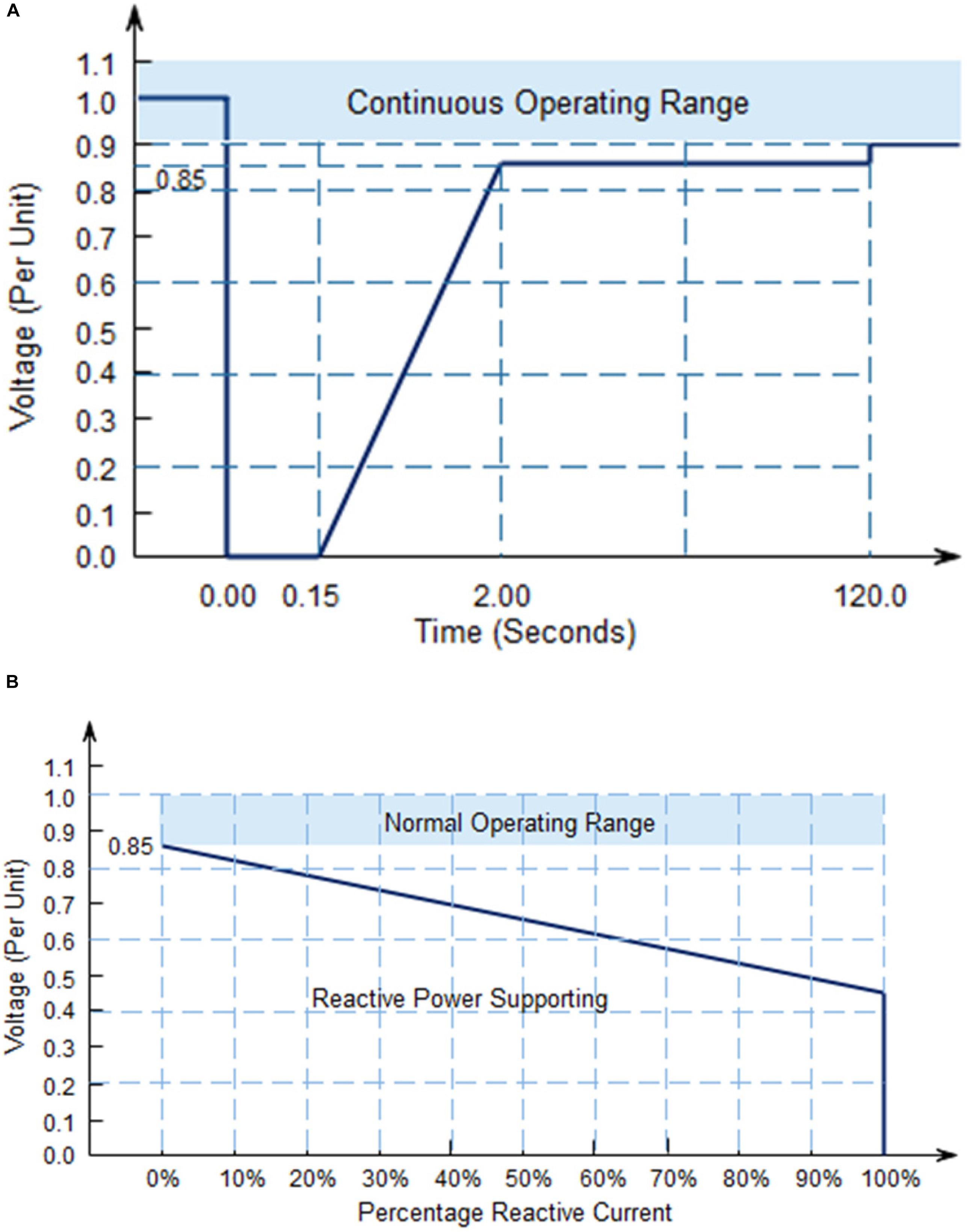
Figure 1. (A) South Africa Low Voltage Ride-Through (LVRT) curve. (B) Stipulated reactive current ranges (generated or consumed) to the voltage level.
The dynamic voltage support is triggered for LVRT operation in the event of a voltage drop of more than ± 15 percent of the rated voltage. The grid code stipulates the possible reactive current supply of at least 100 percent of the rated current, depending on the voltage sag depth, as shown in Figure 1B.
Proposed Fast DSC for LVRT Secondary Control
The negative and positive sequence components of voltage and current signals need to be obtained for LVRT application (Shabestary and Mohamed, 2018). The positive-sequence component and negative-sequence components are separated by traditional DSC techniques described in the literature using Eqs. 1 and 2. This accurate sequence separation process involves a delay of the signal within a quarter of the fundamental frequency.
The traditional DSC algorithm demonstrated in Figure 2A, where two components t1 and t2 of vαβ(t) are rotated counter-clockwise (Gude and Chu, 2019a; Gude et al., 2019b; Rasheduzzaman and Kimball, 2019). Subsequently, in Figure 2B, the fundamental delay cycle vαβ(t−fs/4⋅fg) are applied respectively to extract components t1. Consequently, this adds a phase shift delay of -π to the component t1. Hence, a phase shift delay of -2π is added to the component t2. Therefore, the backward rotation clock compensates by the addition of +π to the two components’ phases. Consequently, t1 is rotated back to its initial position. Thus, the component t1 is doubled in length, and t2 is reduced to zero with the superimposition of Figures 2A,B, with the results shown in Figure 2C.
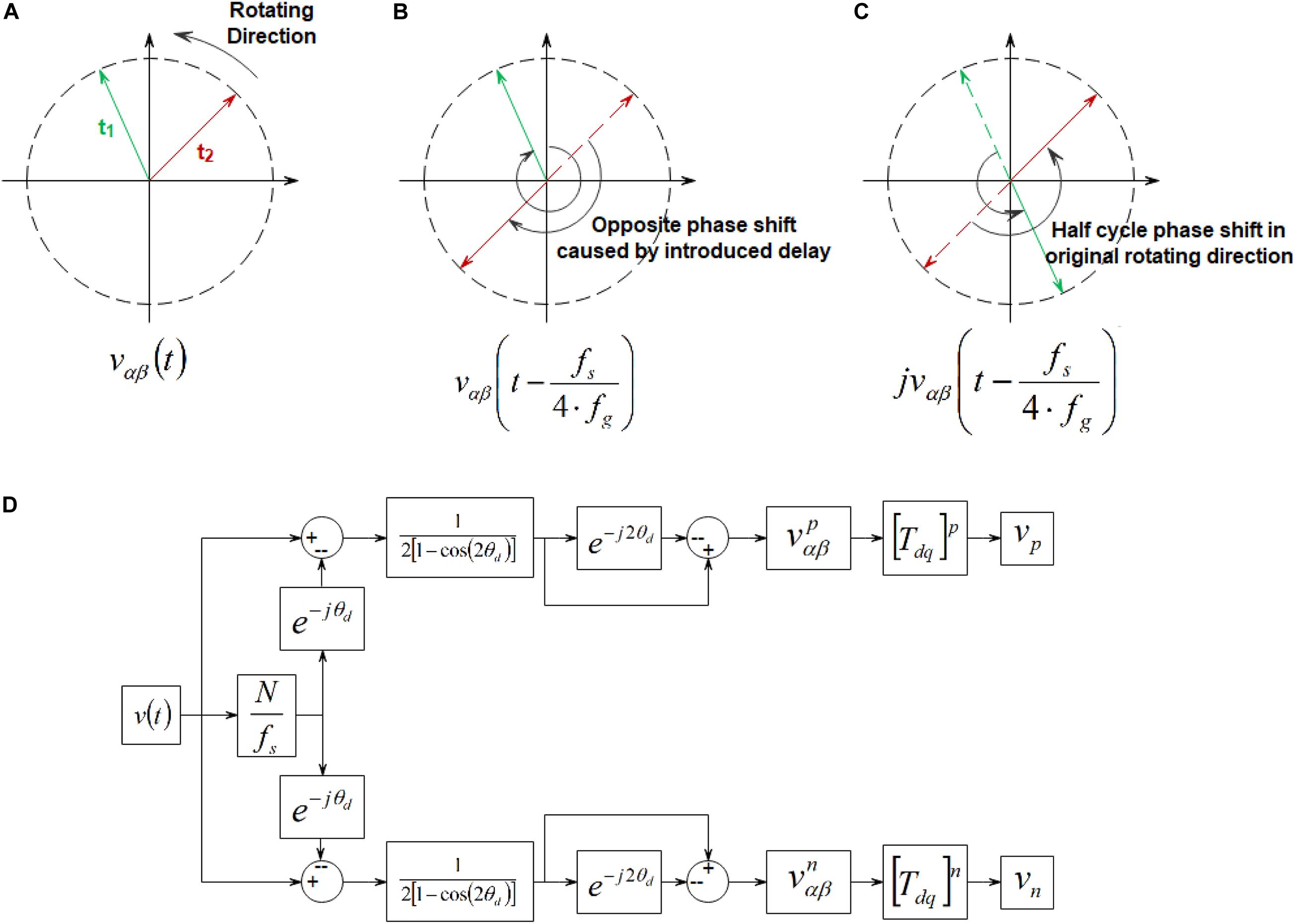
Figure 2. Traditional Delayed Signal Cancelation (DSC) algorithm. (A) Counter-clockwise rotation. (B) Fundamental delay cycle. (C) Resultant. (D) Fast delay signal cancelation algorithm.
The fast DSC implemented in this work is different from the conventional DSC used in Buraimoh et al. (2019) with the substantial delay (5 ms for 50 Hz) incurred as a result of using and , which is a significant weakness. Similarly, the ration fs/4⋅fg must be an integer which is not realistic in actual implementation. A further drawback of and is that the vector vαβ(t−fs/4⋅fg) requires a relatively high memory. The Fast DSC implemented for sequence component separation has a reduced settling time.
The voltage vector vαβ consists of both positive and negative components as expanded by Eq. 3:
Such that
Where ϕ1and ϕ2 are chosen as random angles depicting negligible phase shifts. Thus, Eqs. 1 and 2 can be expanded as a result of Eq. 4 as given in Eqs. 5 and 6.
Hence, the filtered version of the vαβ(t)is expressed as v(t)where
Where θdis the delay angle expressed as in Eq. 8.
The voltage vector v is derived by applying Eqs. 3 and 4 to Eq. 7 as expressed in Eq. 9.
Hence the negative sequence component is canceled out in Eq. 9 as further expressed in Eq. 10.
Therefore, the negative component canceled out is expressed by Eq. 11.
The positive and negative sequence components are similar to that of traditional DSC provided that the delay angle in Eqs. 10 and 11 approaches zero, as expressed in Eq. 8. Hence a time delay of fs/N seconds, which corresponds to the θd as given in Eq. 8. Thus, at the exact delay angle θdπ/2, the output of the traditional DSC is achieved. However, the delay can be made greater than 5 ms with noise.
Suppose
therefore, the sequence component estimates in the stationary reference frame are given as Eqs. 13–16.
The proposed fast DSC deployed for the secondary control is given in Figure 2D. A transformation from αβ0 stationary reference frame to dq0 rotating reference frame is performed using Eq. 17.
The positive and negative component voltage-independent control is done in conformity with their respective sequence references is expressed in Eq. 18:
where kpp and kpn are the PI control’s proportional gains for the positive sequence while kip and kin are the integral gains in the negative sequence. In this work, grid supporting is required to aid grid voltage recovery by the reactive power injection, especially during faults in the grid. Furthermore, this injection will, in turn, contribute to the overall stability and reliability of the system. The mandatory reactive power injection (dynamic grid support) in meeting the grid code requirements is summarized in Eq. 19, according to the South African network code (Buraimoh et al., 2019). Consequently, the required reactive current injection under fault in the AC grid is guided by Eq. 19.
VgN is the nominal grid voltage value, QN is the inverter’s rated reactive power, and Qref is estimated based on the depth of voltage sag as shown in Eq. 19. The secondary control is activated when the grid voltage drops beyond 0.85 per unit. The reactive power injection is regulated to restore the voltage above 0.85 per unit. Thus, the reactive power estimated corresponds to the voltage sag depth with the complex power limit of the interfacing inverter to forestall overloading. The reactive power injection control is implemented in the proposed strategy as an LVRT solution by generating active power P∗ and reactive power Q∗ references for the primary control to supply a current reference for the grid and load as given in Eq. 20. The reference P∗ for active power is accurately tracked at the maximum power PMPP, (P∗ = PMPP), and Q∗ = 0 VAr under grid normal operating mode at the unity power factor. However, the reference Q∗ is generated to inject reactive power under fault concerning the grid code stipulations. The support requirement ensures that the injection is comparable to the depth of the voltage sag:
The inverter-based microgrids are expected to operate near the unity power factor at maximum power. Hence, there is minimal or no reactive power injection until voltage sag, which implies that = 0 at 1 per unit grid voltage The grid codes also require a sufficiently minimal reactive current injection for static voltage support and allow for power factor compensation in a steady-state (Buraimoh and Davidson, 2020). For instance, a minimum reactive current Iq is injected into the grid once the grid voltage level decreases to 90% of the nominal voltage. Under the fault, the extent to which active power is generated and reactive power is injected is constrained by the complex power limit Smax of the inverter, as shown in Figure 3. Figure 3 ensures compliance with the inverter’s rated limit for complex power. This constraint is considered in designing the proposed LVRT strategy. Hence, the preventing of DC-AC converter trip-off because of over-current protection.
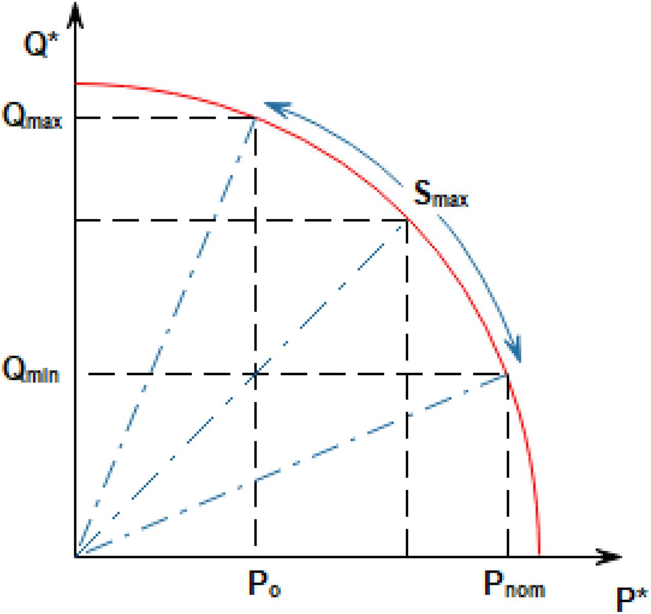
Figure 3. Power referencing for Low Voltage Ride-Through (LVRT) operation in an inverter-based microgrid. P* and Q* are the references for active power and reactive power, respectively.
As a result of the constraints imposed by Figure 3, the inverter’s overcurrent tripping during the voltage faults is avoided when the injected current peak is maintained constant. This constraint is consequently considered in developing the LVRT scheme, active power curtailment, and operation of the inverter-based microgrid.
DER Control and Stability Analysis
The secondary control provides the active and reactive power references to the primary control. The primary control consists of the droop, the power control, and the current controls (Lou et al., 2019; Xu et al., 2019; Zuo et al., 2020). The power calculation is determined by Eq. 21 for both active and reactive power.
Where vd and vq are the d-axis and q-axis voltages, respectively. Similarly, id and iq are the d-axis and q-axis current, respectively. In a grid supporting grid feeding system, the q-axis voltage is controlled to 0 by the PLL. Thus, d-axis and q-axis currents are directly associated with the active and reactive power, respectively. The corresponding d-axis and q-axis current references and are given by Eq. 22. Considering the need for reactive power injection in Eq. 20 by grid code, the AC grid current in the direct-quadrature reference equivalent is given by Eq. 22.
The small-signal model of the grid supporting grid feeding control used for each of the interfacing converters for the DERs is given in Figure 4.
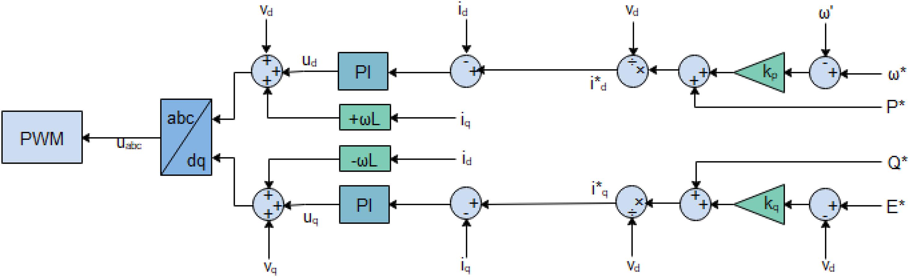
Figure 4. Small signal model of the grid supporting grid feeding DER control. P* and Q* are the references for active power and reactive power, respectively. I*d and I*q are the references for the direct and quadrature currents. E* and ω* are the references for the frequency and voltage, respectively.
The grid supporting grid feeding control’s main function is to ensure that the LCL filter’s current output tracks the d-axis and q-axis current references and . The cross-coupled terms - and are expunged at the controllers’ output; thus, the new reference voltage ud and uq are transmitted to the Pulse Width Modulation (PWM), which generates the commensurate duty cycles.
The LCL filter dynamics of the grid supporting grid feeding inverter are given by Eqs. 23–25.
where iabc is the three-phase output current of the inverter, vCabc is the three-phase voltage across the three-phase capacitor branch, vabc is the three-phase output voltage for the inverter, vGabc and iGabc are the three-phase voltage and current of the grid on the secondary side of the transformer. Eqs. 23–25 can be expressed per phase for each of the phases. VS and VP indicates the rated RMS voltages of the transformer, the ratio of the two thereby constituting the transformer turn ratio.
Eqs. 23–25 are expressed in the space phasor domain and thus separately expressed in stationary reference as the grid supporting grid feeding is based on d-axis and q-axis control. The resulting equations are decoupled into real and imaginary components. The control signal ud and uq outputs of the PI controller, which track the error between id and iq current and their references, are given by Eq. 26.
From Eq. 26, the internal states of the two PI controllers are by
The complete close loop state space differential equations of the grid supporting grid feeding converter for both d-axis and q-axis are given as
The state-space model for small perturbation is given as
where
The grid supporting grid feeding inverter control parameters alongside power circuit parameters are given in Table 1.
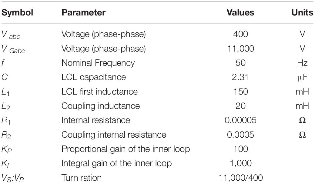
Table 1. Control and LCL parameters.
Results and Discussion
An eigenvalue analysis is performed on the linearized small-signal model to determine the critical changes resulting from the variation in parameters that may impact the system stability. The poles and zeros of the grid supporting grid feeding control are given in Figure 5. All the poles and zeros are on the left half-plane, which ensures overall system stability.
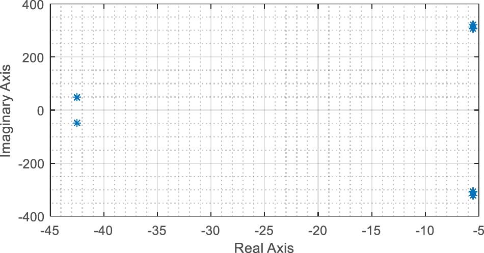
Figure 5. Poles and zeros plot from eigenvalue analysis. *Are points on the graph (real and imaginary).
The selected parameters are given in Table 1, the step response from the reference d-axis and q-axis current to the d-axis and q-axis current are given in Figure 6. The response has overshoot and settling time of 0.2 and 0.069 s, respectively.
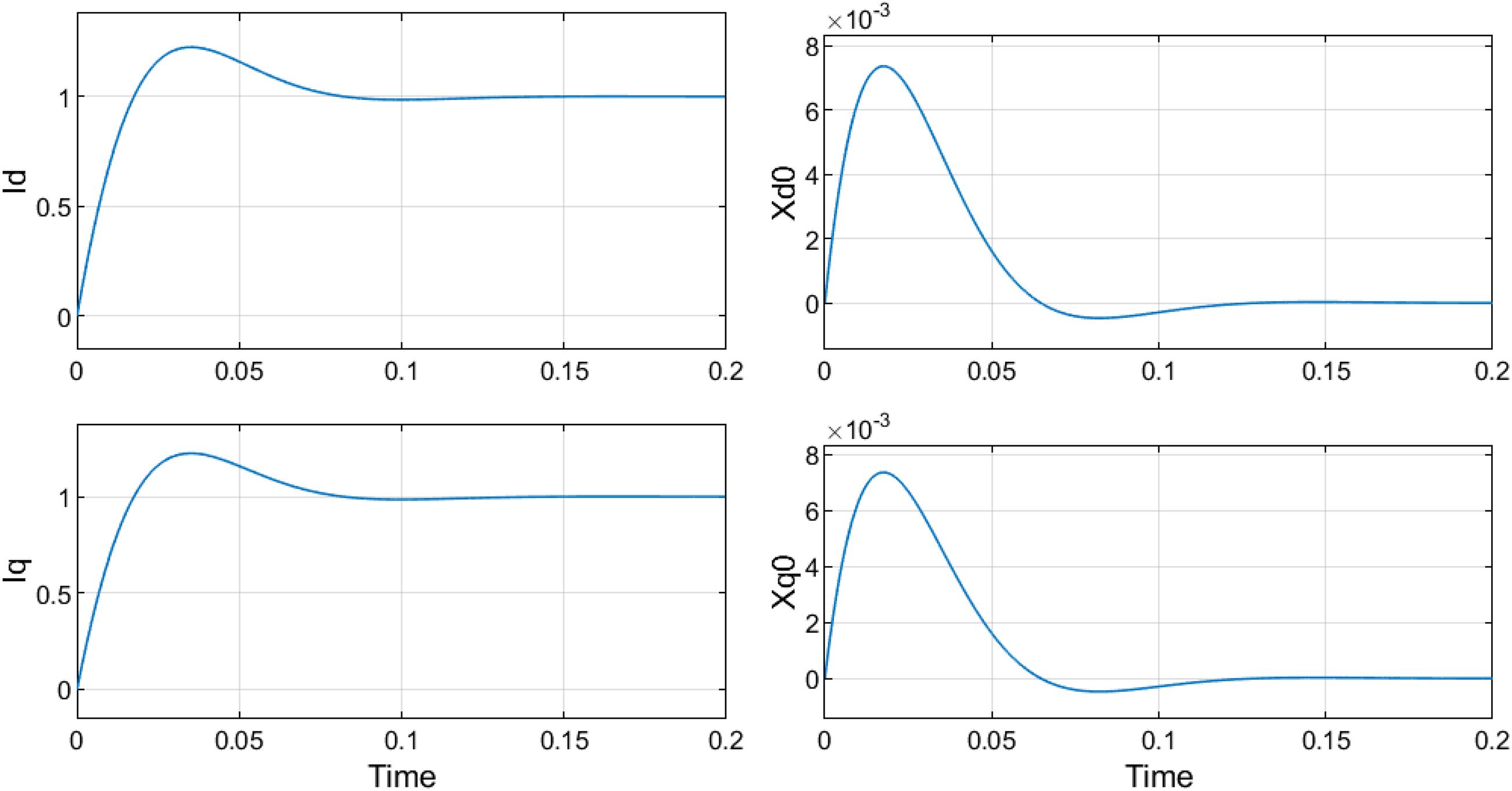
Figure 6. Simultaneous units step response of in d-axis and q-axis reference current.
The LVRT approach’s effectiveness, proposed with the DSC secondary level control, is examined on the systems illustrated in Figure 7. The system has four DERs and a local load. Symmetric voltage sag 60% is simulated between time t = 1.0–1.1 s and t = 1.3–1.8 s within the grid. The DER units 1, 2, 3, and 4 are connected to the microgrid via interfacing DC-AC inverters of the capacities listed in Table 2. These inverters are critical to operation and microgrid performance. DERs with interfacing parallel inverters collectively contribute to the grid frequency (P-F) and voltage regulation (Q-V). This ensures proportional load sharing within the grid-interactive microgrid.
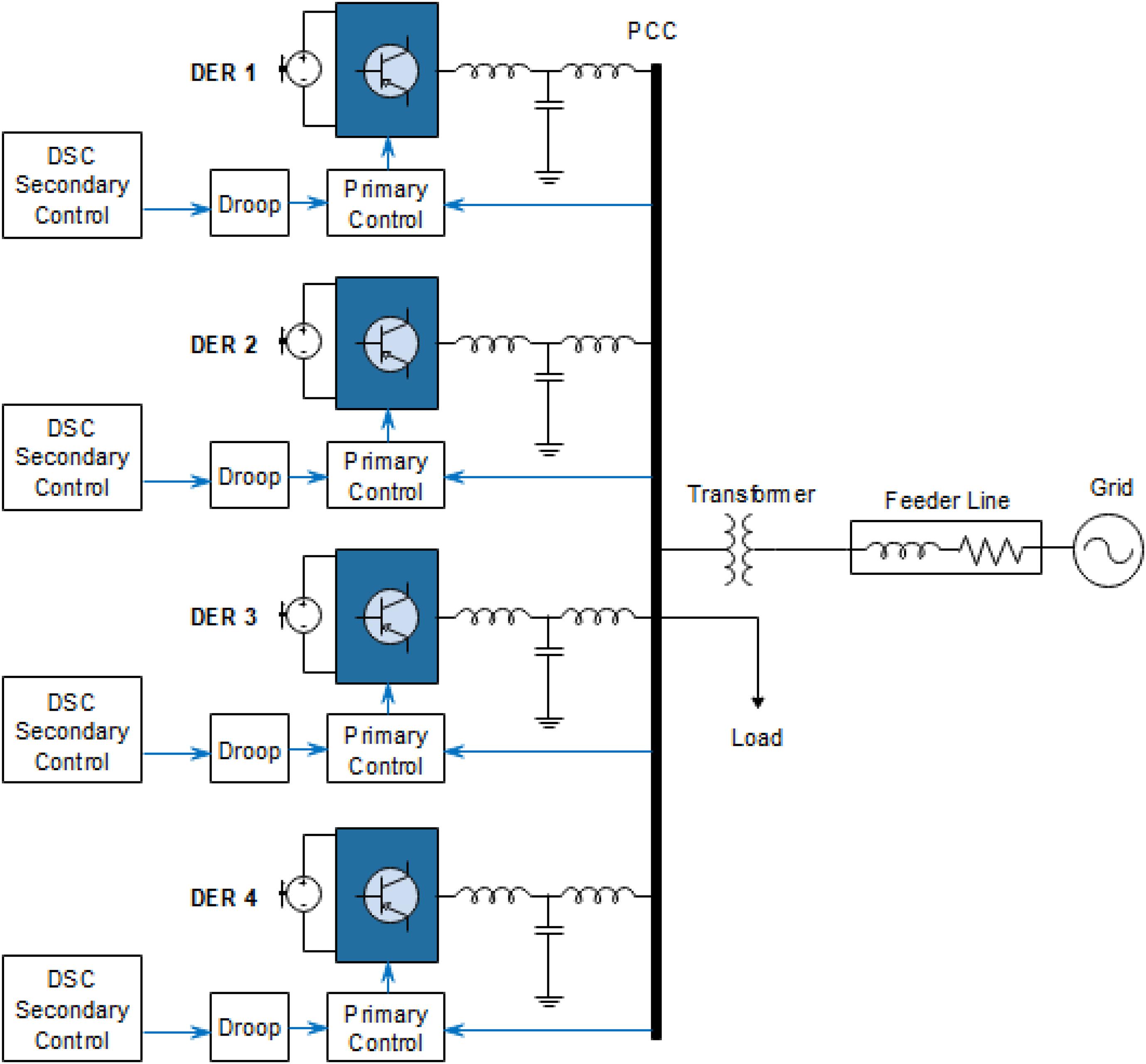
Figure 7. Decentralized DSC secondary level control for inverter based microgrid.
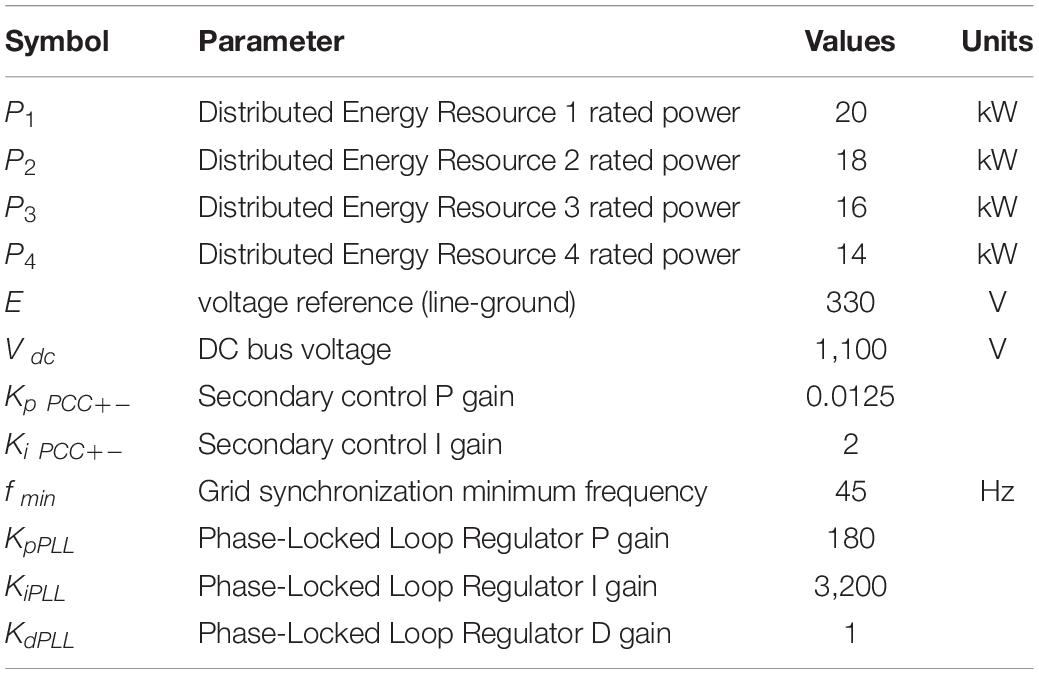
Table 2. System parameters.
For the grid voltage sag of 60%, the output voltages of the DERs are shown in Figures 8A,B, 9A for the none compensated system (no secondary control), central secondary control, and distributed secondary control using fast DSC detections, respectively. Due to lack of coordination for the reactive power generation within the microgrid, the injection of reactive power to suppress the 60% voltage sage at the grid, the voltage rise to the tune of 1.25 per unit was observed within the microgrid—voltages across the DERs and, by extension, the microgrid without the secondary control. The LVRT scheme in place at the secondary in the centralized and decentralized can proportionately improve the grid voltage sag within the microgrid without exceeding the stipulated grid code voltage margin. In Figure 8A, the microgrid voltage, as observed in the DERs’ output voltage, indicates that the microgrid voltage does not drop below 0.90 per unit for the centralized secondary control and 0.95 per unit for the decentralized.
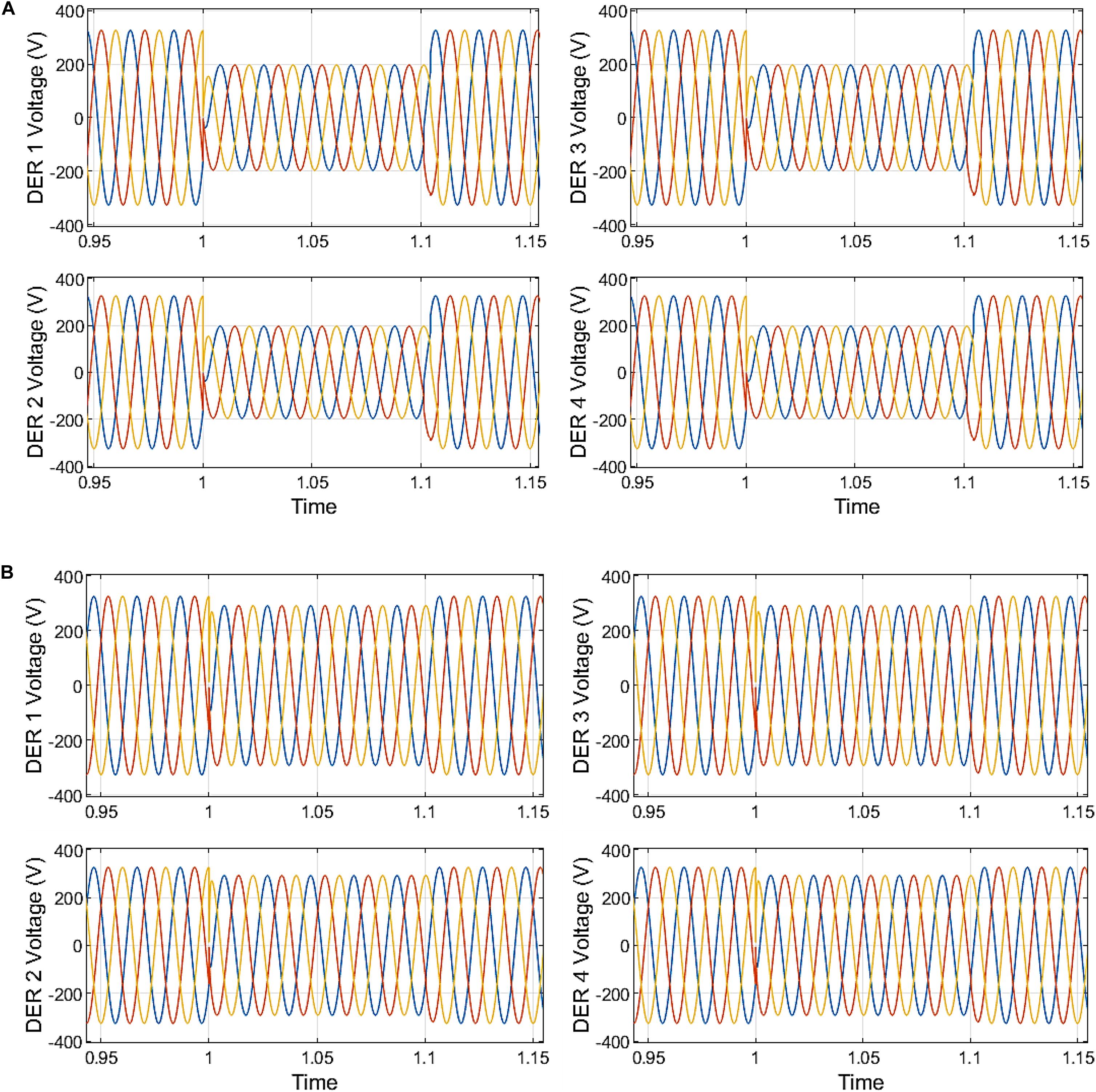
Figure 8. (A) Microgrid voltage without secondary control. (B) Microgrid voltage with centralized secondary control.
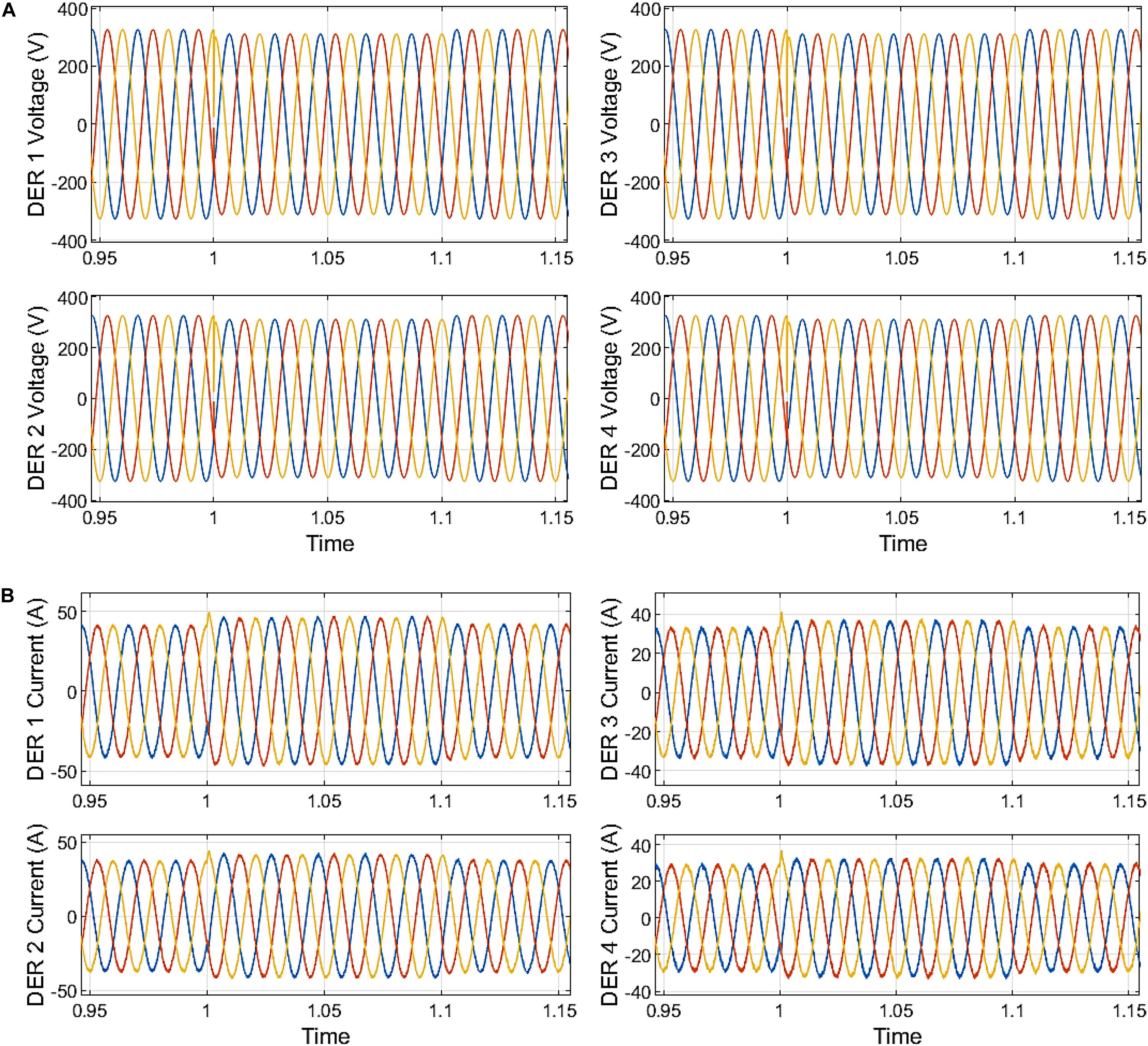
Figure 9. (A) Microgrid voltage with distributed secondary control. (B) Microgrid DER output current centralized secondary control.
The current outputs of the DER are appropriately curtailed with minor distortion with amplitude curtailed in the first cycle after fault inception at 1.0 s. Fault current is observed across the LCL filter capacitor, and fault current inception overshoot disappears instantaneously. Without the secondary control, the peak amplitude currents for each of the DER are given in Figure 9A. Thus, DER 1 output current reached 59.06 A at the inception of fault at 1.007 s, while the current reached 57.31 A at the clearance of the sag. DER 2 output current reached 53.09 A at 1.018 s while the current reached 50.62 A at the clearance of the sag. DER 3 output current reached 47.92 A at 1.007 s, while the current reached 43.94 A at the clearance of the sag. DER 4 output current reached 41.50 A at 1.028 s, while the current reached 38.39 A at the sag’s clearance.
With the centralized secondary control, the peak amplitude currents for each of the DER are given in Figure 9B. Thus, DER 1 output current reached 47.30 A at the inception of fault at 1.068 s. DER 2 output current reached 42.63 A at the inception of fault at 1.048 s. DER 3 output current reached 37.73 A at the inception of fault at 1.027 s. DER 4 output current reached 32.82 A at the inception of fault at 1.048 s. The current output of the DERs under the centralized secondary control shows an insignificant rise in the peak at the sag’s clearance. With the distributed secondary control, the peak amplitude currents for each of the DER are given in Figure 10A. DER 1 output current reached 44.20 A at the inception of fault at 1.047 s. DER 2 output current reached 39.76 A at the inception of fault at 1.047 s. The output current of DER 3 reached 35.32 A at the inception of fault at 1.027 s. DER 4’s output current reached 30.89 A at the inception of fault at 1.027 s. The current output of the DERs under the distributed secondary control show an insignificant rise in the peak at the clearance of the sag.
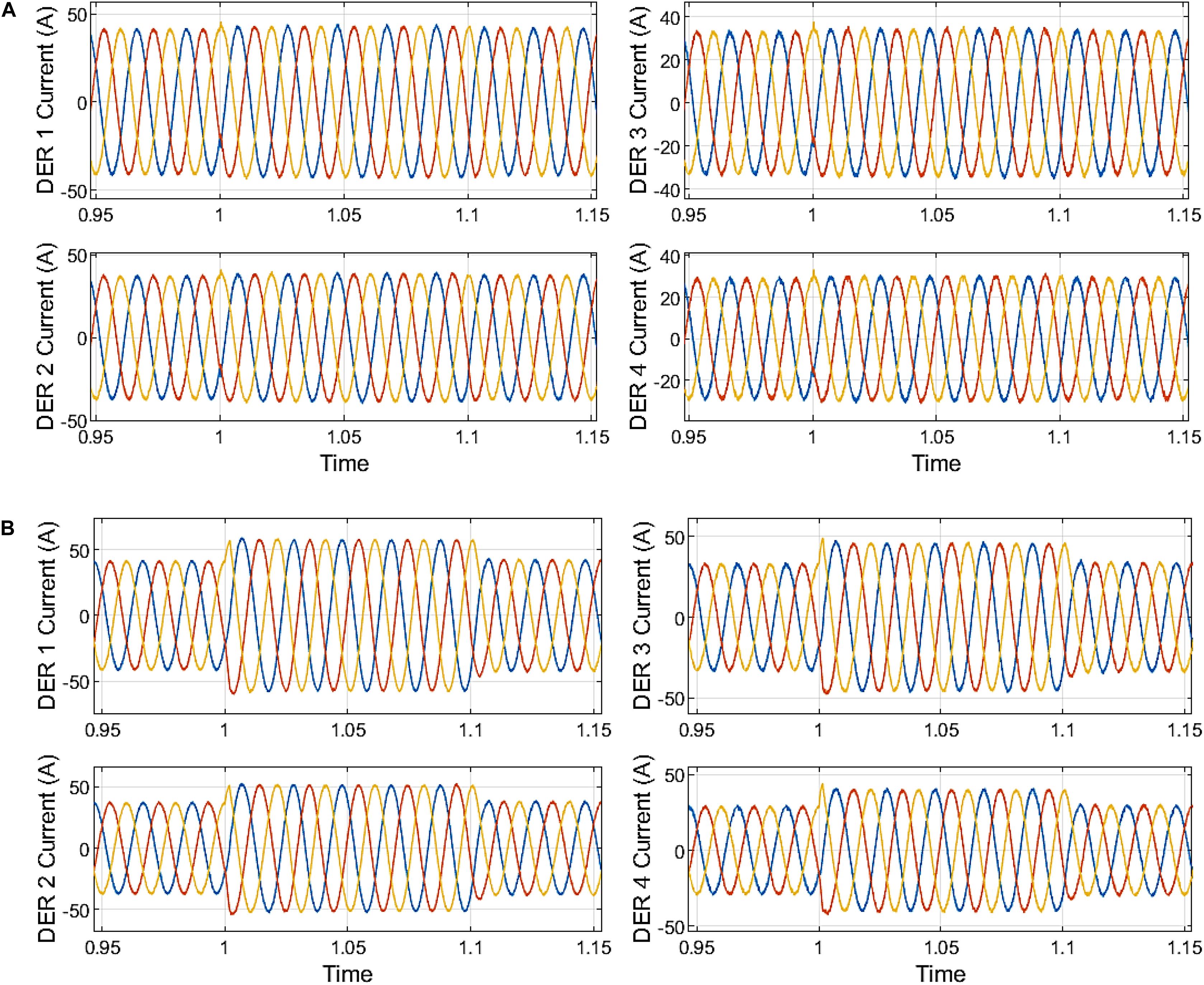
Figure 10. (A) Microgrid DER output current distributed secondary control. (B) Microgrid DER output current without secondary control.
The fast current amplitude curtailment is achieved in power referencing for both centralized and distributed secondary control in compliance with the apparent power limit. Following the EN50160 standard, the THD of output voltage waveforms of DERs must not exceed 8% (EN Std, 2001). Similarly, FFT inspection of the current and voltage waveforms reveals compliance with IEC 61000-3-2 standard (International Electrotechnical Commission, 2000) and affirms this fast DSC algorithm’s effectiveness for the LVRT secondary control in the inverter-based microgrids.
The increase in the reactive power injection restricts active power generation to fulfill the LVRT and design requirements. Under the fault period, the increased reactive power generation supports the microgrid voltage and forces it within the acceptable range, as depicted in Figures 9B, 10A compared to Figure 10B. At the time t = 1.1 s, the fault clearance is instantly effected; the LVRT scheme senses an increase in main grid voltage at the PCC to a reasonable range of 0.85–1.10. The reactive power injection is also decreased depending on the degree of voltage increase. Assuming a voltage sag between time t = 1.3–1.8 s, the active power limitations under the 60% depth of voltage sags are presented in Figure 11A for the uncompensated system without secondary control, Figure 11B for a microgrid with centralized DSC secondary control, and Figure 12A for a microgrid with distributed DSC secondary control.
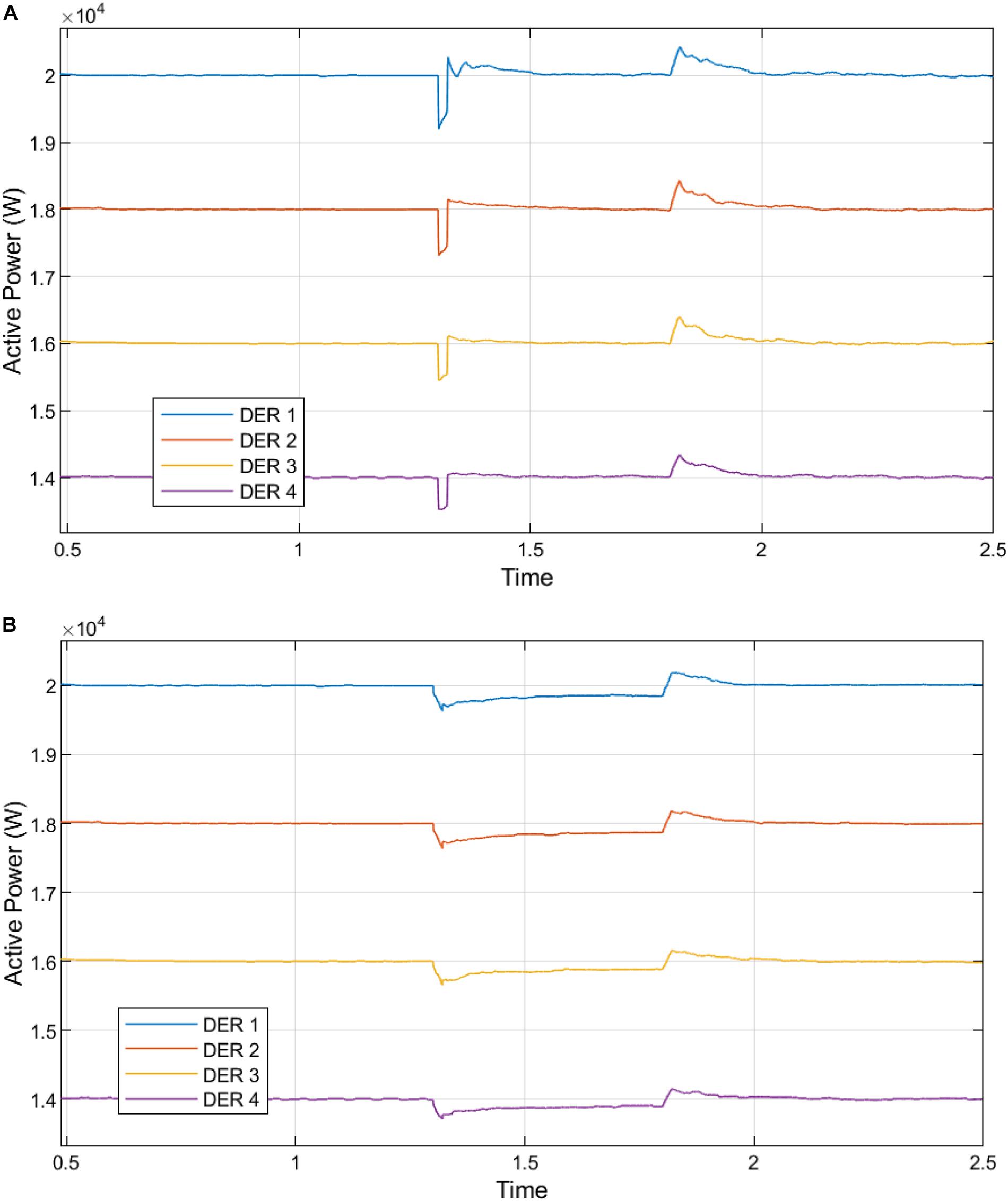
Figure 11. (A) Active power generation from the DERs in the microgrid without fast DSC secondary control. (B) Active power generation from the DERs in the microgrid with centralized DSC secondary control.
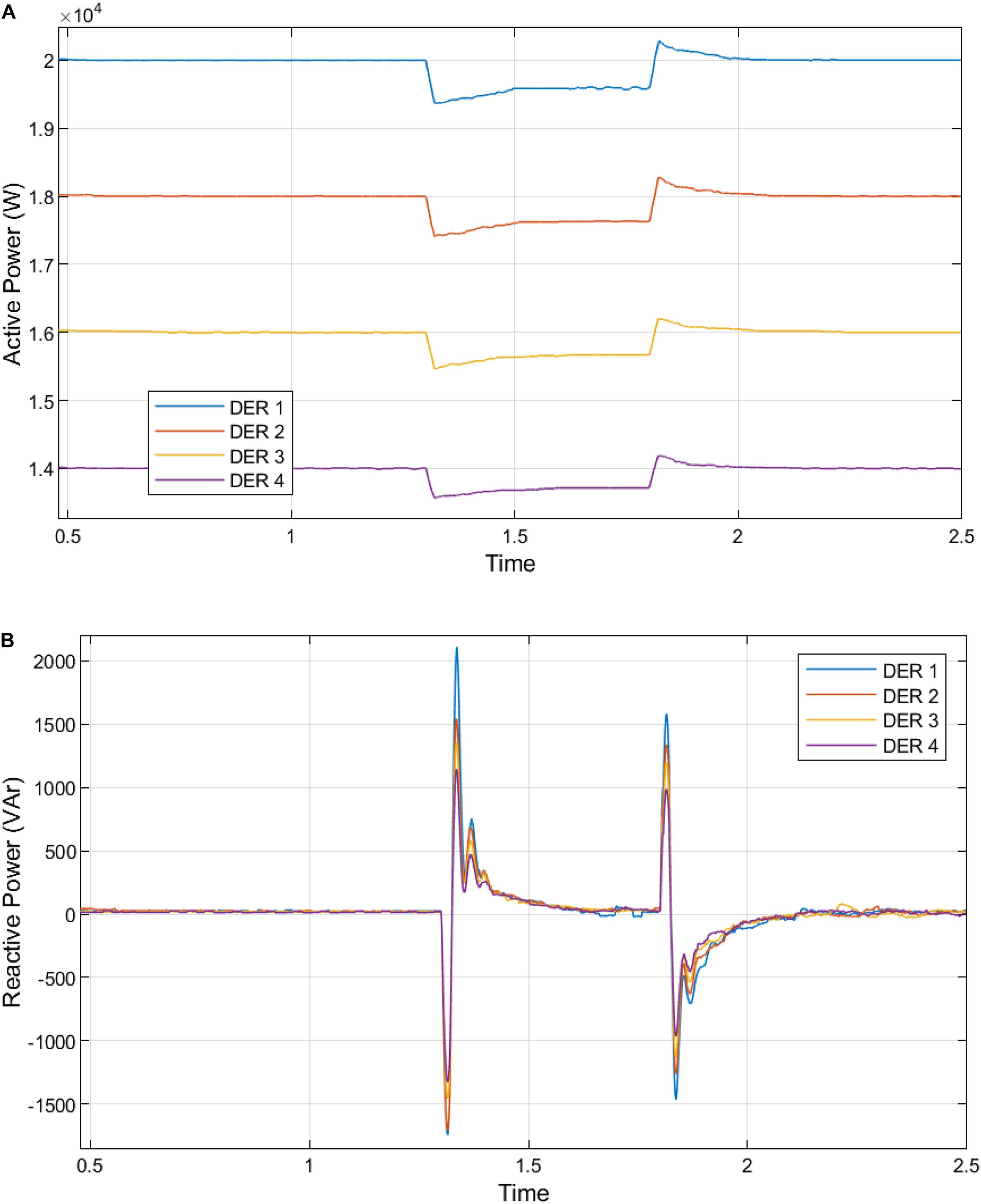
Figure 12. (A) Active power generation from the DERs in the microgrid with distributed DSC secondary control. (B) Reactive power generation from the DERs in the microgrid without fast DSC secondary control.
Similarly, Figures 12B, 13A,B show the reactive power injection increase with a corresponding curtailment in active power. The centralized and distributed implementations of this LVRT control with the fast DSC. The distributed fast DSC used at the secondary control was compared and evaluated compared to centralized DSC secondary control and a primary droop control without a secondary control.
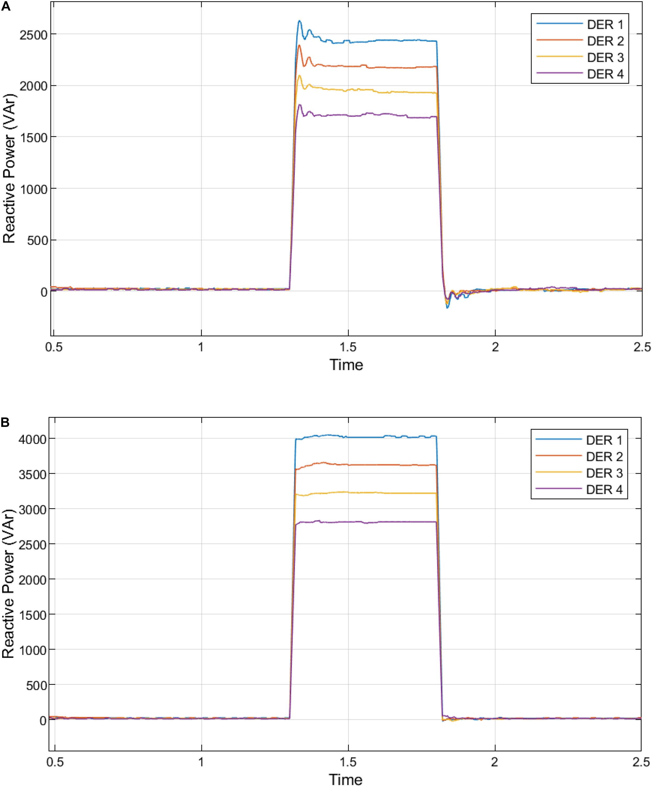
Figure 13. (A) Reactive power generation from the DERs in the microgrid with centralized DSC secondary control. (B) Reactive power generation from the DERs in the microgrid with distributed DSC secondary control.
The analysis of Figures 11A,B–13A,B are presented in Supplementary Tables S3–S6. The proposed decentralization of the fast DSC algorithm for secondary level control provides the best response at fault inception and clearance. Due to the voltage drop caused by grid failure, the aggregate active power supply by DERs is reduced.
The DERs are regulated to inject an amount of active power that meets the demand for local loads and decreases active power injection into the faulty main utility grid. In compliance with South African grid codes, DER reactive power generation is maximized to sustain the host grid’s voltage.
Conclusion
This research proposes a distributed secondary control scheme for dynamic control and inverter-based microgrid using the fast DSC detection techniques for reactive power injection or absorption and active power curtailment. The fast DSC algorithm provided a precise and fast detection of fault by identifying, starting, ending, and analyzing the voltage dip or swell for appropriate compensation and mitigation process. The secondary FRT control stipulates set-points for primary control. These two control levels form a hierarchical control system, and the strategy does not require a mode switch—resynchronization of microgrid as proposed in a seamless transition method after fault clearance is avoided. The respective DERs regulate the active power and reactive power in the microgrid to meet local demand requirements, and the surplus microgrid power is exported to the main grid. Implementing this LVRT control with the sag techniques tracks the main grid disturbance using the voltage sag sensed at the PCC. Furthermore, the fast DSC operation at the centralized and decentralized secondary control is compared, evaluated, and compared under the same sag levels to establish accurate power-sharing and enhanced LVRT operation.
Data Availability Statement
All datasets generated for this study are included in the article/Supplementary Material, further inquiries can be directed to the corresponding author/s.
Author Contributions
EB and FM-R: conceptualization, methodology, formal analysis, and software. ID: conceptualization, methodology, formal analysis, writing—review and editing, and validation. EB: validation, writing—original draft preparation, and writing—review and editing. All authors contributed to the article and approved the submitted version.
Conflict of Interest
The authors declare that the research was conducted in the absence of any commercial or financial relationships that could be construed as a potential conflict of interest.
Supplementary Material
The Supplementary Material for this article can be found online at: https://www.frontiersin.org/articles/10.3389/fenrg.2021.643920/full#supplementary-material
References
Basak, R., Bhuvaneswari, G., and Pillai, R. R. (2020). Low-voltage ride-through of a synchronous generator-based variable speed grid-interfaced wind energy conversion system. IEEE Trans. Ind. Appl. 56, 752–762. doi: 10.1109/TIA.2019.2946125
Buraimoh, E., and Davidson, I. E. (2020). “Overview of fault ride-through requirements for photovoltaic grid integration, design and grid code compliance,” in Proceedings of the 9th International Conference on Renewable Energy Research and Applications, ICRERA 2020, (Glasgow, UK: Institute of Electrical and Electronics Engineers Inc), 332–336. doi: 10.1109/ICRERA49962.2020.9242914
Buraimoh, E., Davidson, I. E., and Fernando, M.-R. (2019). Fault ride-through enhancement of grid supporting inverter-based microgrid using delayed signal cancellation algorithm secondary control. Energies 12:3994. doi: 10.3390/en12203994
Çelik, D., and Meral, M. E. (2020). Voltage support control strategy of grid-connected inverter system under unbalanced grid faults to meet fault ride through requirements. IET Gener. Trans. Distribution 14, 3198–3210. doi: 10.1049/iet-gtd.2019.1206
Das, P. P., and Chattopadhyay, S. (2018). A voltage-independent islanding detection method and low-voltage ride through of a two-stage pv inverter. IEEE Trans. Ind. Appl. 54, 2773–2783. doi: 10.1109/TIA.2017.2788433
Dawn, S., Tiwari, P. K., Goswami, A. K., and Panda, R. (2019). An approach for system risk assessment and mitigation by optimal operation of wind farm and FACTS devices in a centralized competitive power market. IEEE Trans. Sustain. Energy 10, 1054–1065. doi: 10.1109/TSTE.2018.2859770
Easley, M., Jain, S., Shadmand, M. B., and Abu-Rub, H. A. (2020). Autonomous model predictive controlled smart inverter with proactive grid fault ride-through capability. IEEE Trans. Energy Convers. 35, 1825–1836. doi: 10.1109/tec.2020.2998501
EN Std (2001). Voltage Characteristics of Electricity Supploed by Public Distribution Systems. Brussels: EuropeanCommittee on Electro-Technical Standardization.
Feng, F., and Zhang, P. (2020). Enhanced microgrid power flow incorporating hierarchical control. IEEE Trans. Power Syst. 35, 2463–2466. doi: 10.1109/TPWRS.2020.2972131
Geng, Y., Yang, K., Lai, Z., Zheng, P., Liu, H., and Deng, R. (2019). A novel low voltage ride through control method for current source grid-connected photovoltaic inverters. IEEE Access 7, 51735–51748. doi: 10.1109/ACCESS.2019.2911477
Gude, S., and Chu, C. C. (2019a). Single-phase enhanced phase-locked loops based on multiple delayed signal cancellation filters for micro-grid applications. IEEE Trans. Ind. Appl. 55, 7122–7133. doi: 10.1109/TIA.2019.2915563
Gude, S., Chu, C. C., and Vedula, S. V. (2019b). Recursive implementation of multiple delayed signal cancellation operators and their applications in prefiltered and in-loop filtered PLLs under adverse grid conditions. IEEE Trans. Ind. Appl. 55, 5383–5394. doi: 10.1109/TIA.2019.2927190
Hagh, M. T., and Khalili, T. (2018). A review of fault ride-through of PV and wind renewable energies in grid codes. Int. J. Energy Res. 43, 1342–1356. doi: 10.1002/er.4247
He, X., Geng, H., Li, R., and Pal, B. C. (2020). Transient stability analysis and enhancement of renewable energy conversion system during LVRT. IEEE Trans. Sustain. Energy 11, 1612–1623. doi: 10.1109/TSTE.2019.2932613
International Electrotechnical Commission (2000). Limits for Harmonic Current Emissions. Geneva: International Electrotechnical Commission.
Kou, W., and Wei, D. (2018). Fault ride through strategy of inverter-interfaced microgrids embedded in distributed network considering fault current management. Sustain. Energy Grids Netw. 15, 43–52. doi: 10.1016/J.SEGAN.2017.12.003
Liu, X., Li, C., Shahidehpour, M., Gao, Y., Zhou, B., Zhang, Y., et al. (2019). Fault current hierarchical limitation strategy for fault ride-through scheme of microgrid. IEEE Trans. Smart Grid 10, 6566–6579. doi: 10.1109/TSG.2019.2907545
Lopez, M. A. G., De Vicuna, J. L. C., Miret, J., Castilla, M., and Guzman, R. (2018). Control strategy for grid-connected three-phase inverters during voltage sags to meet grid codes and to maximize power delivery capability. IEEE Trans. Power Electro. 33, 9360–9374. doi: 10.1109/TPEL.2018.2792478
Lou, G., Gu, W., Wang, J., Sheng, W., and Sun, L. (2019). Optimal design for distributed secondary voltage control in Islanded microgrids: communication topology and controller. IEEE Trans. Power Syst. 34, 968–981. doi: 10.1109/TPWRS.2018.2870058
Lu, X., Wang, J., Guerrero, J. M., and Zhao, D. (2018). Virtual impedance based fault current limiters for inverter dominated AC microgrids. IEEE Trans. Smart Grid 3053, 1599–1612. doi: 10.1109/TSG.2016.2594811
Ma, C., Gao, F., He, G., and Li, G. (2015). A voltage detection method for the voltage ride-through operation of renewable energy generation systems under grid voltage distortion conditions. IEEE Trans. Sustain. Energy 6, 1131–1139. doi: 10.1109/TSTE.2014.2331684
Merabet, A., Labib, L., and Ghias, A. M. Y. M. (2018). Robust model predictive control for photovoltaic inverter system with grid fault ride-through capability. IEEE Trans. Smart Grid 9, 5699–5709. doi: 10.1109/TSG.2017.2694452
Mojallal, A., and Lotfifard, S. (2019). Enhancement of grid connected PV arrays fault ride through and post fault recovery performance. IEEE Trans. Smart Grid 10, 546–555. doi: 10.1109/TSG.2017.2748023
Mortazavian, S., and Mohamed, Y. A. R. I. (2018). Dynamic analysis and improved LVRT performance of multiple DG units equipped with grid-support functions under unbalanced faults and weak grid conditions. IEEE Trans. Power Electron. 33, 9017–9032. doi: 10.1109/TPEL.2017.2784435
Piya, P., Ebrahimi, M., Karimi-Ghartemani, M., and Khajehoddin, S. A. (2018). Fault ride-through capability of voltage-controlled inverters. IEEE Trans. Ind. Electron. 65, 7933–7943.
Rasheduzzaman, Md., and Kimball, J. W. (2019). Modeling and tuning of an improved delayed-signal-cancellation PLL for microgrid application. IEEE Trans. Energy Convers. 34, 712–721. doi: 10.1109/TEC.2018.2880610
Shabestary, M. M., and Mohamed, I. (2018). Advanced voltage support and active power flow control in grid-connected converters under unbalanced conditions. IEEE Trans. Power Electron. 33, 1855–1864. doi: 10.1109/TPEL.2017.2695646
Taul, M. G., Wang, X., Davari, P., and Blaabjerg, F. (2020). Robust fault ride through of converter-based generation during severe faults with phase jumps. IEEE Trans. Ind. Appl. 56, 570–583. doi: 10.1109/TIA.2019.2944175
Wu, X., Xu, Y., He, J., Wang, X., Vasquez, J. C., and Guerrero, J. M. (2020). Pinning-based hierarchical and distributed cooperative control for AC microgrid clusters. IEEE Trans. Power Electron. 35, 9867–9887. doi: 10.1109/TPEL.2020.2972321
Xiao, Y., and Peng, L. (2020). A novel fault ride-through strategy based on capacitor energy storage inside MMC. IEEE Trans. Power Electron. 35, 7960–7971. doi: 10.1109/TPEL.2020.2964074
Xu, Y., Sun, H., Gu, W., Xu, Y., and Li, Z. (2019). Optimal distributed control for secondary frequency and voltage regulation in an Islanded microgrid. IEEE Trans. Ind. Inform. 15, 225–235. doi: 10.1109/TII.2018.2795584
Yuan, H., Xin, H., Huang, L., Wang, Z., and Wu, D. (2019). Stability analysis and enhancement of type-4 wind turbines connected to very weak grids under severe voltage sags. IEEE Trans. Energy Convers. 34, 838–848. doi: 10.1109/TEC.2018.2882992
Keywords: inverter, microgrid, fault ride though (FRT), low voltage ride-through (LVRT), delayed signal cancelation (DSC)
Citation: Buraimoh E, Davidson IE and Martinez-Rodrigo F (2021) Decentralized Fast Delayed Signal Cancelation Secondary Control for Low Voltage Ride-Through Application in Grid Supporting Grid Feeding Microgrid. Front. Energy Res. 9:643920. doi: 10.3389/fenrg.2021.643920
Received: 19 December 2020; Accepted: 22 February 2021;
Published: 15 April 2021.
Edited by:
Zhao Xu, Hong Kong Polytechnic University, Hong KongReviewed by:
Rui Wang, Northeastern University, ChinaKenneth Okedu, Caledonian College of Engineering, Oman
Copyright © 2021 Buraimoh, Davidson and Martinez-Rodrigo. This is an open-access article distributed under the terms of the Creative Commons Attribution License (CC BY). The use, distribution or reproduction in other forums is permitted, provided the original author(s) and the copyright owner(s) are credited and that the original publication in this journal is cited, in accordance with accepted academic practice. No use, distribution or reproduction is permitted which does not comply with these terms.
*Correspondence: Elutunji Buraimoh, elutunji@gmail.com