Ultra-Broadband Sound Absorbing Materials Based on Periodic Gradient Impedance Matching
 Fei Wu
 Xiao Zhang
 Zegang Ju
 Jiang Zhao2
 - 1College of Mechanical and Vehicle Engineering, Chongqing University, Chongqing, China
- 2College of Engineering and Technology, Southwest University, Chongqing, China
Ultra-broadband sound absorption with periodic gradient impedance matching is of great concern in the research of acoustic materials. This study investigates the impedance matching of composite acoustic metamaterials comprising micro-perforated plates (MPPs) and subsequent Fabry–Pérot(FP) channels. Based on the impedance matching theory, ultra-broadband sound absorption has been realized through a design with 36 channels whose thickness is only 50 mm. Also, the average sound absorption coefficient of 88% and an absorption frequency bandwidth (490–4000 Hz) can be achieved by preserving the matching impedance. Furthermore, by changing the thickness of the perfect absorber being 100 mm, the average sound absorption coefficient can reach greater than 90% in the frequency range of 250–4500 Hz. The proposed structure is validated analytically and experimentally. This work can help with designing and improving the method of acoustic metasurfaces and especially have the potential in ultra-broadband sound absorber designs.
Introduction
Broadband noise widely exists in mechanical engineering and aerospace engineering. In recent years, acoustic metamaterials have developed rapidly due to their excellent broadband sound absorption performance and flexible spatial arrangement and occupation. The total thickness of a micro-perforated plate (García-Chocano et al., 2012; Wang et al., 2014; Jiménez et al., 2016; Tang et al., 2017; Ryoo and Jeon, 2018), decorated membrane resonators (DMRs) (Yang et al., 2008, 2015; Ma et al., 2013, 2014; Yang and Sheng, 2017; Wang et al., 2018), and coiled-up channel (Cai et al., 2014; Li and Assouar, 2016; Liu et al., 2017; Shen et al., 2019) is much less than the wavelength at the working frequency. The appearance of acoustic metamaterials makes up for the defect that the structure of traditional porous materials (Biot, 1962) and porous plate absorbers (Sakagami et al., 2009) is too large in size for low-frequency sound absorption. Owing to the characteristics of deep sub-wavelength thickness and adjustable bandwidth of acoustic metamaterials, the design of ultra-broadband sound absorbers turns into one of the most notable subjects in this field. Usually, the optimization method for broadening the bandwidth is to skillfully combine different units of metamaterials in series or in parallel. Based on this method, a series of broadband sound absorbers are obtained (Qian et al., 2017; Bucciarelli et al., 2019; Mosa et al., 2019). A double-layered DMR structure with an interval of 28mm was proposed. It had four discrete absorption peaks in the range of 100–1000 Hz, and the sound absorption performance in the frequency band between the absorption peaks was unsatisfactory (Mei et al., 2012). Some scholars arranged a micro-perforated plate above 25 coplanar imperfect Helmholtz resonators to achieve efficient sound absorption in the 870–3224 Hz frequency band, and the thickness of the structure was 3.9 cm (Huang et al., 2020). A new type of sound absorber comprising six rectangular labyrinth sound-absorbing units was proposed, in which the rectangular labyrinth was arranged in a hexagonal shape. The research results showed its strong sound-absorbing performance in the range of 400–1400 hz (Kumar and Lee, 2020). Y. Han et al. improved the sound absorption bandwidth and reduced the working frequency by using the coiled channel with variable cross-sections (Han et al., 2020). Some scholars proposed a sound absorber suitable for high-temperature environments, which is a double-layered structure comprising two perforated plates and a honeycomb structure. At 100°C, its broadband sound absorption capacity is more than three times higher than that of the traditional structure (Li et al., 2021). M. Duan et al. introduced an embedded neck and rubber coating based on the Helmholtz resonator. The design realized quasi-perfect absorption from 306 to 921 Hz, which achieved a low-frequency broadband perfect absorption at the 100-Hz level of underwater acoustics (Duan et al., 2021). The size of the sound absorber structure tends to increase while broadening the frequency band, which limits its application in engineering. According to its structural characteristics, the spiral channel has two characteristics: low frequency and sub-wavelength. Scholars proposed a metamaterial sound absorber with a thickness of 115.8 mm comprising multiple parallel spatial crimped FP channels, which can achieve quasi-perfect absorption from 400 to 3,000 Hz (Yang et al., 2017). In another work, 10 coiled FP channels with sound absorption peak gradient were connected in parallel with the cotton filled, and the average sound absorption coefficient in the frequency band of 500–2,000 Hz was greater than 0.9 (Chang et al., 2018). Recently, a 72-mm-thick sound absorber comprising one micro-perforated plate and 12 back cavity units showed excellent broadband sound absorption and achieves quasi-perfect sound absorption in the frequency band of 380–3,600 Hz (Rui Liu et al., 2020). In the aforementioned research, for achieving both low-frequency and broadband sound absorption, the size of the sound absorber tends to be larger than single functional designs, and meanwhile, the working space in special applications is very limited. To promote the application of metamaterials in engineering, it is necessary to balance low-frequency, broadband, and structural size in the design. With its unique structural characteristics, the FP channel has good performance in low frequency and small size.
In this study, we design an ultra-broadband sound absorber comprising 36 units, each of which comprises a micro-perforated plate and a coiled-up channel or a straight channel. Through the observation of the relative impedance of the structure, it can be found that the gradient parallel has a good impedance matching. The average sound absorption coefficient of the proposed absorber is 0.89 in the frequency range of 490–4,000 Hz, and the thickness of the structure is only 1/13 wavelength (50 mm). In addition, by increasing the channel length to 100 mm, the broadband of the design is further broadened, and the average sound absorption coefficient reaches 0.886 at 250–4,500 Hz with a thickness wavelength ratio of only 1/14.
Gradient Design for Impedance Matching
Structural Design
As shown in Figure 1A, for the ultra-broadband sound absorber, each basic unit comprises a coiled-up channel (yellow part) or a straight channel (green part), and a micro-perforated plate is placed above the channels. With respect to the flatness and space utilization of the structure, we limit the thickness of the structure to 50 mm. The appropriate channel equivalent length is obtained by increasing the number of channel folding. The micro-perforated plate is introduced to use its large acoustic impedance to absorb low-frequency noise with a shorter equivalent sound absorption length. The coiled-up channels are introduced to double the equivalent sound absorption length through the folding of the channels to further decrease the working resonance frequency and the occupied space of the structure. The thickness of the structure is 50 mm (the thickness of the micro-perforated plate is 0.5 mm), and the cross-sectional area of all channels is 8.5 mm × 8.5 mm. The diameter of the micropores is 0.3 mm, and the perforation rate is 7%. The depth of the cavity behind the plate is 50 mm, and the side length is 58 mm (considering the thickness of the sidewall). It is worth noting that the units are separated by baffles to form an independent sound absorption channel. By gradually changing the height of the baffle relative to the micro-perforated plate, the coiled-up channel and sub-channel (straight channel) with equivalent sound absorption length gradient are obtained. In fact, when the length gradient of the coiled-up channel drops below the thickness of the structure, it becomes a straight channel. We place it in the remaining space after the channel is folded to maximize the use of space and make the structure more compact. Figure 1B shows the three-dimensional structure of the coiled-up channel, and the main structural parameters are indicated. The sound wave propagation direction is parallel to the z-axis, and the red dotted line represents the equivalent propagation path of the sound wave in the channel.
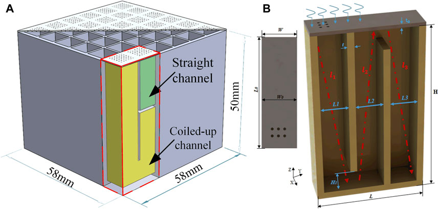
FIGURE 1. (A) Ultra-broadband sound absorber. (B) Three-dimensional structure of the coiled-up channel.
Theoretical Calculation
Generally, the overall performance of a sound absorber is characterized by the sound absorption coefficient of Eq. 1.
Here,
where
For
where the kinematic viscosity
By assembling multiple acoustic units with different resonance characteristics in parallel, the broadband noise can be absorbed perfectly without adding other sound-absorbing materials (such as sound-absorbing cotton, etc.). The acoustic impedance of a sound absorber comprising multiple sound absorption units is calculated by Eq. 6 (Huang et al., 2020).
where
Performance Analysis
In this section, we analyze the performance of the sound absorption unit from the perspective of relative impedance. The micro-perforated plate and its upper area are defined as the pressure acoustic domain when establishing the numerical model. The micro-perforated plate and folded channels are defined as the thermal viscous acoustic domain as shown in Figure 2A. Figure 2B shows the sound absorption performance of the basic unit with a channel length of 79 mm, and the theoretical results (blue line) and numerical results (red dots) are both calculated. It can be seen from the figure that the coiled-up channel can have multiple absorption peaks in a wide frequency range, which represents the multiorder resonance frequency of the sound absorption structure, making broadband sound absorption easier. Figure 2E shows the relative impedance diagram of the device. When the impedance matches well, perfect sound absorption can be achieved. Moreover, the imaginary part of the relative impedance is equal to 0, and the real part is equal to 1. In particular, the imaginary part curve of the relative impedance intersects the zero line three times, two of which correspond to the absorption peak in Figure 2B. The remaining one corresponds to the absorption valley of the curve, which is caused by the large deviation of the real part from the ideal value. Then, we assembled another unit with a channel length of 91.5 mm in parallel, and its relative impedance curve is shown in Figure 2F. It can be seen that the imaginary part curve is easier to converge to the best straight line. In the frequency band near 2,500 Hz, the real part and imaginary part are very close to the ideal state, and the sound absorption curve in Figure 2C shows that the average sound absorption coefficient in this part of the frequency band is more than 0.9. In order to further broaden the frequency band, we assembled another unit with a channel length of 58.5 mm in parallel to form a three-channel structure, and its sound absorption curve and relative impedance curve are shown in Figures 2D,G. It can be seen that the impedance matching has been further improved. Although the sound absorption coefficient of the high-frequency part has decreased, the low-frequency part of more interest has been significantly widened.
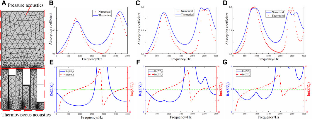
FIGURE 2. (A) Schematic diagram of the gradient parallel numerical model. (B–D) Sound absorption curve before and after parallel connection. (E–G) Relative acoustic impedance after parallel connection.
Based on the results of the 3-channel parallel arrangement, we speculate that adding parallel elements (according to the gradient) will help the relative impedance curve of the overall structure converge to the optimal value locally or globally in a wide frequency range, which will also be reflected in the final design. The channel number and channel length of the sound absorber designed in this article are shown in Figure 3 and Table 1 , respectively.
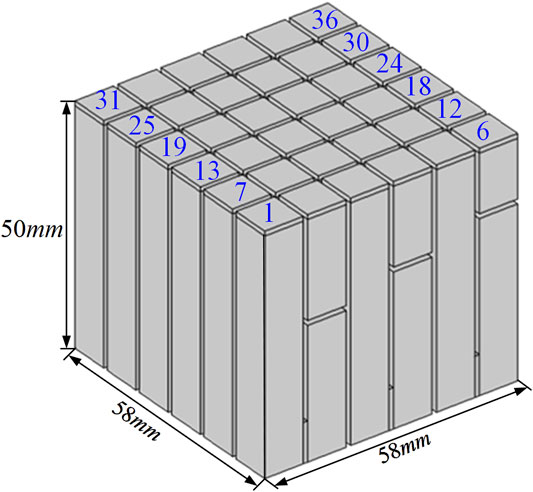
FIGURE 3. 36-channel structure and channel number.
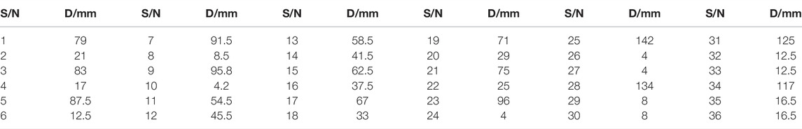
TABLE 1. Channel length of each sound absorption unit.
The sound absorption performance of the absorber is calculated by theoretical calculation and numerical simulation. In Figure 4A, the theoretical and numerical solutions prove the effectiveness of the results by mutual verification. The average sound absorption coefficient of the sound absorption structure in the frequency range of 490–4,000 Hz reaches 0.893. Moreover, perfect sound absorption is achieved at multiple frequency positions
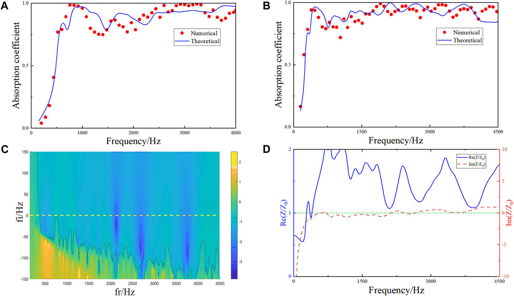
FIGURE 4. (A) Sound absorption characteristic curve of a 50-mm structure obtained by theoretical and numerical simulation. (B) Sound characteristic absorption curve of a 100-mm structure. (C) Reflection coefficient in complex frequency planes for a 100-mm structure. (D) Relative impedance diagram of the 100-mm structure.
Test Verification
In this study, the theoretical calculations, numerical simulations, and experiments are compared to ensure the accuracy of the conclusion. The experimental equipment is shown in Figure 5A. The cross section of the waveguide is square (60 × 60 mm) and made of an acrylic plate to simulate sound-hard boundary conditions. One side of the waveguide is the loudspeaker, which is used as the input of the test, and the other side is the place where the sample is installed. The microplate of the experimental sample is made of a metal material, and the micropores on the microplate are cut by laser. The channel under the plate is made of resin 3D printing and connected with the plate by gluing. The sound transfer function is obtained by calculating the sound pressure signals collected by two sensors arranged above the waveguide. The sound transfer functions of the two signals are obtained by measuring the sound pressure at the two sensors. The incident sound pressure and reflected sound pressure and the sound absorption coefficient of the sample are calculated on this basis.
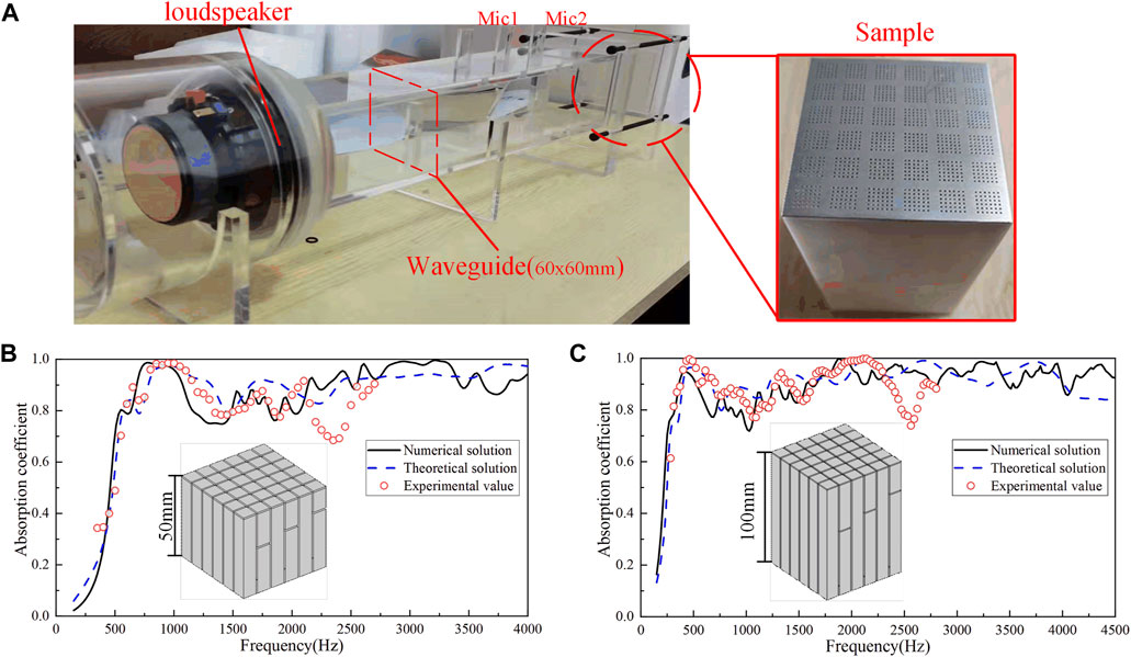
FIGURE 5. (A) Experimental setup. (B) Absorption coefficients of 50-mm samples (C) Absorption coefficients of 100-mm samples.
The cutoff frequency of the test system is 2,700 Hz, and the comparison of experimental and simulation results is shown in Figures 5B,C. There is a slight deviation between the experimental results and the simulation within the test range, among which most prominence is found near 2,500 Hz, which is mainly due to the manufacturing error of the sample and the gap between the components of the test system. Generally speaking, the experimental results are in good agreement with the simulation results. It can be proven that the two designed structures perform well in low frequency and broadband sound absorption.
Conclusion
In this study, a 36-channel ultra-broadband sound absorber based on gradient parallel connection is designed, in which each channel comprises a crimped channel and micro-perforated plate. Theoretical, simulation, and experimental results show that the broadband sound absorption structure achieves high-efficiency sound absorption with an average sound absorption coefficient of 0.893 in the frequency range of 490–4,000 Hz with a structural thickness of 50 mm, and the sound absorption coefficient reaches 0.8 at 550 Hz with the thickness–wavelength ratio of the sound absorption structure being only 1/13. In addition, the structure achieves an average sound absorption coefficient of 0.886 in the 250–4,500 Hz frequency band with a thickness of 100mm, and the sound absorption coefficient reaches 0.8 at 250 Hz. Moreover, the thickness-to-wavelength ratio is 1/14. Both designs meet the sub-wavelength requirements, and the sound absorption bandwidth is greatly improved compared with the traditional sound absorption structure. The proposed structures are easy to manufacture and have great potential applications in noise control engineering. Through the research of impedance matching, the gradient parallel design of the structure can effectively broaden the sound absorption band, which provides an effective design method for broadband sound absorption structures.
Data Availability Statement
The original contributions presented in the study are included in the article/Supplementary Material; further inquiries can be directed to the corresponding author.
Author Contributions
FW: conceptualization and writing—review and editing. XZ: methodology and writing—original draft. ZJ: investigation and software. JZ: data curation. MH: resources and writing—review and editing. HP: project administration. JL: supervision. MG: resources.
Funding
This work was supported by the Key Laboratory of aeroacoustics and the AVIC Aerodynamics Research Institute.
Conflict of Interest
The authors declare that the research was conducted in the absence of any commercial or financial relationships that could be construed as a potential conflict of interest.
Publisher’s Note
All claims expressed in this article are solely those of the authors and do not necessarily represent those of their affiliated organizations, or those of the publisher, the editors, and the reviewers. Any product that may be evaluated in this article, or claim that may be made by its manufacturer, is not guaranteed or endorsed by the publisher.
References
Biot, M. A. (1962). Generalized Theory of Acoustic Propagation in Porous Dissipative Media. J. Acoust. Soc. Am. 34, 1254–1264. doi:10.1121/1.1918315
Bucciarelli, F., Malfense Fierro, G. P., and Meo, M. (2019). A Multilayer Microperforated Panel Prototype for Broadband Sound Absorption at Low Frequencies. Appl. Acoust. 146, 134–144. doi:10.1016/j.apacoust.2018.11.014
Cai, X., Guo, Q., Hu, G., and Yang, J. (2014). Ultrathin Low-Frequency Sound Absorbing Panels Based on Coplanar Spiral Tubes or Coplanar Helmholtz Resonators. Appl. Phys. Lett. 105, 121901. doi:10.1063/1.4895617
Chang, H., Liu, L., Zhang, C., and Hu, X. (2018). Broadband High Sound Absorption from Labyrinthine Metasurfaces. AIP Adv. 8, 045115. doi:10.1063/1.5024303
Duan, M., Yu, C., Xin, F., and Lu, T. J. (2021). Tunable Underwater Acoustic Metamaterials via Quasi-Helmholtz Resonance: From Low-Frequency to Ultra-broadband. Appl. Phys. Lett. 118, 071904. doi:10.1063/5.0028135
García-Chocano, V. M., Cabrera, S., and Sánchez-Dehesa, J. (2012). Broadband Sound Absorption by Lattices of Microperforated Cylindrical Shells. Appl. Phys. Lett. 101, 184101. doi:10.1063/1.4764560
Han, Y., Wang, X., Xie, G., Tang, X., and Chen, T. (2020). Low-frequency Sound-Absorbing Metasurface with a Channel of Nonuniform Cross Section. J. Appl. Phys. 127, 064902. doi:10.1063/1.5119408
Huang, S., Zhou, Z., Li, D., Liu, T., Wang, X., Zhu, J., et al. (2020). Compact Broadband Acoustic Sink with Coherently Coupled Weak Resonances. Sci. Bull. 65, 373–379. doi:10.1016/j.scib.2019.11.008
Jiménez, N., Huang, W., Romero-García, V., Pagneux, V., and Groby, J.-P. (2016). Ultra-thin Metamaterial for Perfect and Quasi-Omnidirectional Sound Absorption. Appl. Phys. Lett. 109, 121902. doi:10.1063/1.4962328
Kumar, S., and Lee, H. P. (2020). Labyrinthine Acoustic Metastructures Enabling Broadband Sound Absorption and Ventilation. Appl. Phys. Lett. 116, 134103. doi:10.1063/5.0004520
Li, Y., and Assouar, B. M. (2016). Acoustic Metasurface-Based Perfect Absorber with Deep Subwavelength Thickness. Appl. Phys. Lett. 108, 063502. doi:10.1063/1.4941338
Li, Z., Wang, Z., Guo, Z., Wang, X., and Liang, X. (2021). Ultra-broadband Sound Absorption of a Hierarchical Acoustic Metamaterial at High Temperatures. Appl. Phys. Lett. 118, 161903. doi:10.1063/5.0044656
Liu, L., Chang, H., Zhang, C., and Hu, X. (2017). Single-channel Labyrinthine Metasurfaces as Perfect Sound Absorbers with Tunable Bandwidth. Appl. Phys. Lett. 111, 083503. doi:10.1063/1.4986142
Ma, G., Yang, M., Xiao, S., Yang, Z., and Sheng, P. (2014). Acoustic Metasurface with Hybrid Resonances. Nat. Mater 13, 873–878. doi:10.1038/nmat3994
Ma, G., Yang, M., Yang, Z., and Sheng, P. (2013). Low-frequency Narrow-Band Acoustic Filter with Large Orifice. Appl. Phys. Lett. 103, 011903. doi:10.1063/1.4812974
Mei, J., Ma, G., Yang, M., Yang, Z., Wen, W., and Sheng, P. (2012). Dark Acoustic Metamaterials as Super Absorbers for Low-Frequency Sound. Nat. Commun. 3, 756. doi:10.1038/ncomms1758
Mosa, A. I., Putra, A., Ramlan, R., Prasetiyo, I., and Esraa, A.-A. (2019). Theoretical Model of Absorption Coefficient of an Inhomogeneous MPP Absorber with Multi-Cavity Depths. Appl. Acoust. 146, 409–419. doi:10.1016/j.apacoust.2018.11.002
Qian, Y. J., Zhang, J., Sun, N., Kong, D. Y., and Zhang, X. X. (2017). Pilot Study on Wideband Sound Absorber Obtained by Adopting a Serial-Parallel Coupling Manner. Appl. Acoust. 124, 48–51. doi:10.1016/j.apacoust.2017.03.021
Rui Liu, C., Hui Wu, J., Yang, Z., and Ma, F. (2020). Ultra-broadband Acoustic Absorption of a Thin Microperforated Panel Metamaterial with Multi-Order Resonance. Compos. Struct. 246, 112366. doi:10.1016/j.compstruct.2020.112366
Ryoo, H., and Jeon, W. (2018). Dual-frequency Sound-Absorbing Metasurface Based on Visco-Thermal Effects with Frequency Dependence. J. Appl. Phys. 123, 115110. doi:10.1063/1.5017540
Sakagami, K., Nakamori, T., Morimoto, M., and Yairi, M. (2009). Double-leaf Microperforated Panel Space Absorbers: A Revised Theory and Detailed Analysis. Appl. Acoust. 70, 703–709. doi:10.1016/j.apacoust.2008.09.004
Shen, Y., Yang, Y., Guo, X., Shen, Y., and Zhang, D. (2019). Low-frequency Anechoic Metasurface Based on Coiled Channel of Gradient Cross-Section. Appl. Phys. Lett. 114, 083501. doi:10.1063/1.5081926
Tang, Y., Ren, S., Meng, H., Xin, F., Huang, L., Chen, T., et al. (2017). Hybrid Acoustic Metamaterial as Super Absorber for Broadband Low-Frequency Sound. Sci. Rep. 7, 43340. doi:10.1038/srep43340
Wang, C., Huang, L., and Zhang, Y. (2014). Oblique Incidence Sound Absorption of Parallel Arrangement of Multiple Micro-perforated Panel Absorbers in a Periodic Pattern. J. Sound Vib. 333, 6828–6842. doi:10.1016/j.jsv.2014.08.009
Wang, X., Luo, X., Zhao, H., and Huang, Z. (2018). Acoustic Perfect Absorption and Broadband Insulation Achieved by Double-Zero Metamaterials. Appl. Phys. Lett. 112, 021901. doi:10.1063/1.5018180
Wu, F., Xiao, Y., Yu, D., Zhao, H., Wang, Y., and Wen, J. (2019). Low-frequency Sound Absorption of Hybrid Absorber Based on Micro-perforated Panel and Coiled-Up Channels. Appl. Phys. Lett. 114, 151901. doi:10.1063/1.5090355
Yang, M., Chen, S., Fu, C., and Sheng, P. (2017). Optimal Sound-Absorbing Structures. Mat. Horiz. 4, 673–680. doi:10.1039/C7MH00129K
Yang, M., Meng, C., Fu, C., Li, Y., Yang, Z., and Sheng, P. (2015). Subwavelength Total Acoustic Absorption with Degenerate Resonators. Appl. Phys. Lett. 107, 104104. doi:10.1063/1.4930944
Yang, M., and Sheng, P. (2017). Sound Absorption Structures: From Porous Media to Acoustic Metamaterials. Annu. Rev. Mat. Res. 47, 83–114. doi:10.1146/annurev-matsci-070616-124032
Keywords: metamaterials, sound absorption, broadband, periodic gradient, impedance matching
Citation: Wu F, Zhang X, Ju Z, Zhao J, Hu M, Gao M, Luo J and Pu H (2022) Ultra-Broadband Sound Absorbing Materials Based on Periodic Gradient Impedance Matching. Front. Mater. 9:909666. doi: 10.3389/fmats.2022.909666
Received: 31 March 2022; Accepted: 26 April 2022;
Published: 03 June 2022.
Edited by:
Fuyin Ma, Xi’an Jiaotong University, ChinaReviewed by:
Jie Zhou, Northwestern Polytechnical University, ChinaYawen Wang, University of Texas at Arlington, United States
Copyright © 2022 Wu, Zhang, Ju, Zhao, Hu, Gao, Luo and Pu. This is an open-access article distributed under the terms of the Creative Commons Attribution License (CC BY). The use, distribution or reproduction in other forums is permitted, provided the original author(s) and the copyright owner(s) are credited and that the original publication in this journal is cited, in accordance with accepted academic practice. No use, distribution or reproduction is permitted which does not comply with these terms.
*Correspondence: Man Hu, humanyyyes@126.com