Stability analysis and numerical simulation of foundation in old goaf under building load
 Xiangdong Zhang1
  Wenliang Li
- 1School of Civil Engineering, Liaoning Technical University, Fuxin, Liaoning, China
- 2Beijing Jingneng Geological Engineering Co, Ltd, Beijing, China
This study comprehensively analyzes the safety and stability of old goaf under construction engineering based on specific projects using a variety of research methods. The Beijing Mentougou mining area is used as the research background. The methods of field investigation, laboratory testing, engineering drilling, geophysical exploration, theoretical calculation, and numerical simulation are combined to quantitatively analyze the stability of the foundation and ground buildings in old goaf. The influence depth of the building load and height of the caving crack zone are calculated using the “three-zone theory” to judge if the goaf is at risk of activation. Further simulation is conducted using two types of finite element analysis software, which increases the reliability of the numerical analysis. The results demonstrate that uneven subsidence of approximately 100 mm occurs in the buildings and ground surface, and subsidence of approximately 50 mm occurs in the goaf roof. It is also proven that goaf affects the stability of the surrounding rock and building foundation. Finally, a goaf treatment scheme is proposed. The treatment effect is found to be remarkable through field tests and numerical simulations, ensuring the safety and stability of a building foundation. The combination of theoretical calculation and numerical simulation can effectively evaluate the safety and stability of the project under load, and has a strong promotion and application value. The research results meet the needs of engineering practice, and provide a great reference value for the rational utilization of the land above the old goaf in the Mentougou district of Beijing and similar mining cities, which has a good theoretical significance and application prospect.
1 Introduction
Coal mining forms large-scale mining subsidence areas, which threaten the local ecological environment security and restrict the sustainable development strategy of the mining area and city (Wang et al., 2012; Guo et al., 2021). At the same time, using the site of the underlying goaf as a foundation for a building has become an important measure to solve the problem of land shortage. As such, it is extremely necessary to predict and judge the safety and stability of goaf foundations before building (Zhao et al., 2014; Jia et al., 2022; Sun et al., 2022).
The stability of a foundation can be quantitatively evaluated before a new building is built on the ground of an old goaf according to the spatial relationship between the depth of the load influence and the height of the caving fracture zone of coal seam (Xu et al., 2014; Liu et al., 2015; Zhang et al., 2019). Ren et al. (2022) chose an optimal algorithm to calculate the influence depth of the train load and the development height of the caving fracture zone. The results showed that a ‘particle swarm optimization’ - ‘radial basis function’ neural network model obtained the smallest error, and the prediction was the most accurate. Liu (2017) calculated the critical mining height of different coal seams, considering that the old goaf would be reactivated under the action of building load and the ground would significantly sink. Chen et al. (2022) analyzed that the depth of the building foundation disturbance overlapped with the caving crack zone of the goaf, causing formation instability activation and reducing the safe use of the buildings. In addition, the local hydrogeological conditions should be considered because the permeability and porosity of the overlying rock in the goaf significantly impact the hydraulic characteristics (Ma et al., 2022a; Li et al., 2022). Therefore, the influence of groundwater seepage on the stability of goaf cannot be ignored.
The numerical simulation analysis method has a very good application prospect in the geotechnical field and is suitable for research on the stability analysis of goaf under load (Yasitli and Unver, 2005; Ao et al., 2017; Ma et al., 2022b). Jia et al. (2022) used an open-pit iron mine in China as their engineering research background. The stability analysis and subsidence prediction of shallow goaf were carried out by means of field monitoring and numerical simulation. Yang et al. (2020) studied the stress and displacement characteristics of overlying strata in goaf under a building load after multi-coal seam mining using finite element analysis. The simulated stress-strain results were very close to the later monitoring data. Chen et al. (2019) found that there was a risk of ground collapse under building loads and proposed a governance scheme to effectively guarantee the stability of the goaf. Based on the classical static theory and static numerical simulation, Xiao et al. (2015) comprehensively demonstrated that the mechanical properties of overburdened rock in goafs are significantly affected by rheological and dynamic disturbances, providing a new concept to study the stability of goafs. Gao et al. (2014) proposed a combined numerical method to investigate the failure mechanism of roads above unstable goafs, which are consistent with the actual case. With the progress in science and technology and the gradual completion of modern engineering construction technology, a relatively mature management system has been realized to address challenges in mined-out area backfilling, thus significantly contributing towards the long-term and effective development in mines (Zhu et al., 2017; Shi et al., 2021).
The study presented here comprehensively analyzes the safety and stability of old goaf under construction engineering based on specific projects using a variety of research methods. Further simulation is conducted using two types of finite element analysis software, which increases the reliability of the numerical analysis. Then, a governance plan was proposed based on the analysis results according to the numerical simulation evaluation governance effect, thereby providing a theoretical basis for constructing practical projects. The approach effectively ensures the stability of the overlying strata and building foundation in the goaf, providing significant reference value for similar mining cities to rationally use the land above the old goaf to construct buildings. The research results have accumulated theoretical experiences for the sustainable development of the Mentougou mining area in Beijing and have good practical significance and application prospects.
2 Methods and materials
2.1 Engineering background
The planning area was located in Longquan Town, Mentougou District, Beijing. The overall terrain of the proposed site was not undulating and the landform type was simple. The hydrological conditions of the proposed site were realistic. A seasonal stream, which is a channel for the rainy season drainage in upstream mountainous areas, was observed on the south side. The underground water was buried deep and had minimal influence on the project. Moreover, no pollution source was present near the proposed site. The planned land was located within the scope of the Mentougou well field according to field data and visiting investigations Gao et al. (2022). Additionally, there was a phenomenon of small coal mining in the shallow strata, which mostly did not facilitate supporting measures. The proposed project included lots 6002, 6003, 6007, 6010, and 6011. An orthophoto map of the study area and a digital surface model of the proposed building are shown in Figure 1.
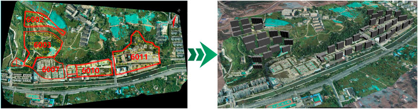
FIGURE 1. An orthophoto map of the study area and digital surface model of the proposed building.
2.2 Exploration of goaf status quo
2.2.1 Drilling information
A DPP-100 vehicle drilling rig was used for geotechnical drilling to ascertain the engineering geology of the proposed site. A total of 190 holes were drilled, the hole depth was between 18.6 and 70.0 m, and part of the rock mass was removed with rock-soil drilling, as shown in Figure 2. The strata of the removed rock and soil mass from the situ and geotechnical tests were divided into five layers according to the characteristics of rock and soil Zhao Y. L. et al. (2021).
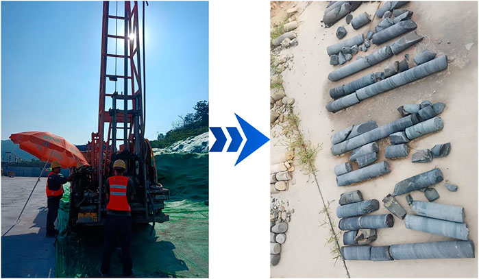
FIGURE 2. Drilling sampling and some rock sample photos.
2.2.2 Geophysical exploration information
A Smartsolo IGU-16 node seismograph and EDJD-3 high-density electrical measurement system were used in this geophysical exploration work to collect data from five plots. The plot 6010 was used an example, with a total of seven active source seismic survey lines and two high-density electrical survey lines arranged in this block. A low-speed anomaly was observed in the shear wave velocity profile obtained by the inversion of one of the survey lines and a low resistivity anomaly in the high-density electrical profile Abedi and Norouzi (2012), as shown in Figure 3. The distribution of the anomalies obtained by geophysical exploration was highly consistent with the drilling information. Therefore, four points showing abnormal physical characteristics were preliminarily divided along the line, and the buried depth location and development characteristics of the goaf were determined.
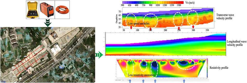
FIGURE 3. Geophysical exploration using instruments, survey line layout and comprehensive interpretation of profile.
2.2.3 Occurrence characteristics of goaf
Drilling and geophysical methods complement and confirm each other. The abnormal distribution area obtained through geophysical exploration was highly consistent with the drilling hole information Olabode et al. (2020). The final summary concluded that there were a number of small coal mined-out areas of different sizes under the proposed construction site. The stratum profile of the mined-out area and its characteristics are shown in Figure 4, considering drill hole G53, the most representative of plot 6010, as an example.
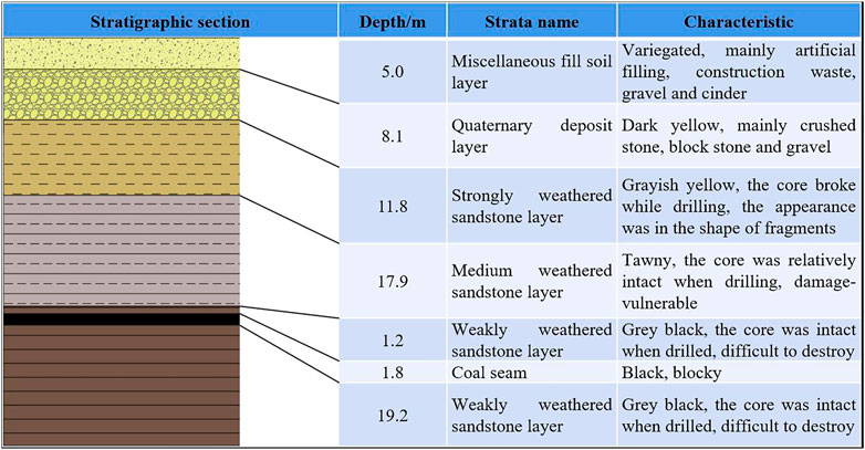
FIGURE 4. The stratum profile of the mined-out area and its characteristics.
2.3 Evaluation of the influence of proposed buildings on the stability of overlying strata in old goaf
2.3.1 Failure height calculation of overlying strata in goaf
2.3.1.1 Distribution and height calculation of caving zone
A caving zone is located directly above the goaf because coal and other entities are mined in large quantities and the surrounding rock has lost its support. Coupled with its own gravity, this leads to stress imbalance, causing the entire rock stratum to sag inward. The development height of a caving zone is closely related to the physical and mechanical properties of the overlying rock mass. The rocks near the caving zone in the goaf of the planned land were mainly sandstone, which is a medium hardness overburden rock. Therefore, the following method was used to calculate the height of the caving zone according to the mining code:
where M is the thickness of the mined coal seam m.
The thickness of coal seam mining is normally approximately 0.2–3.7 m, with 1.8 m as the average thickness of a coal seam, according to the formula. The development height of a caving zone is between 4.4 and 8.8 m.
2.3.1.2 Distribution and height calculation of fracture zone
A fracture zone is located above the caving zone and refers to the rock strata with cracks and separation in the mined-out subsidence area. A fractured rock layer maintains a layered structure to prevent collapse. The fracture zone of medium-hardness overburden is usually approximately calculated to determine the development height of the fracture zone in engineering, according to the following formula:
According to the formula, the maximum height of the fracture zone is between 22.2 and 33.4 m.
The caving and fracture zones are called the caving fracture zone, and its maximum development height is calculated by adding the two values Zhu and Guan (2020). Therefore, the maximum development height of the caving fracture zone is 42.2 m (8.8 m for the caving zone plus 33.4 m for the fracture zone).
2.3.2 Calculation of load influence depth of the proposed building
2.3.2.1 Calculation of dead weight of basement soil
The self-weight stress of the foundation base soil increases with an increase of depth, and the weight of the soil varies at different depths. Therefore, the deadweight stress of the basement soil when there is no external load on the ground is calculated using:
where
2.3.2.2 Base additional stress calculation
Floor loads create additional stress in the rock and soil layers below after constructing the building, which is passed down in a certain way as the increases in depth gradually decrease Nazarimofrad and Barkhordar (2016). The proposed building for this project mostly adopted raft or pile foundations to simplify the calculation of additional stress from the foundation. This can be approximated as a rectangular uniform load and the relevant equations for calculating the influence depth of the building load using the stress coefficient method are as follows:
The calculation formula for the additional stress of the foundation is expressed as:
The calculation formula for the average additional stress of the foundation bottom is expressed as:
The average base pressure calculation formula is expressed as:
where
2.3.2.3 Calculation of influence depth of building load
The planned length of the proposed building was 40 m, the width was 12 m, the buried depth of the foundation was 5.5 m, and the building load per floor was approximately 16 kPa. With an increase in the depths of underground rock and soil layers, the value of the additional stress generated by the building load decreased continuously. Based on the safety principle, the depth of the additional stress of the foundation equal to 10% of the dead weight stress, was regarded as the depth of the disturbance of the foundation under building load. The effect of more than 10-% additional stress depth on the compressive deformation of rock and soil mass was negligible. The calculated values of 10% deadweight stress and building additional stress corresponding to different depths and according to the above formulas are listed in Table 1. The influence depth of the building load foundation for additional stress disturbance depths of the 8F, 10F, and 11F buildings was between 13–14 m, 19–20 m, and 21–22 m, respectively.
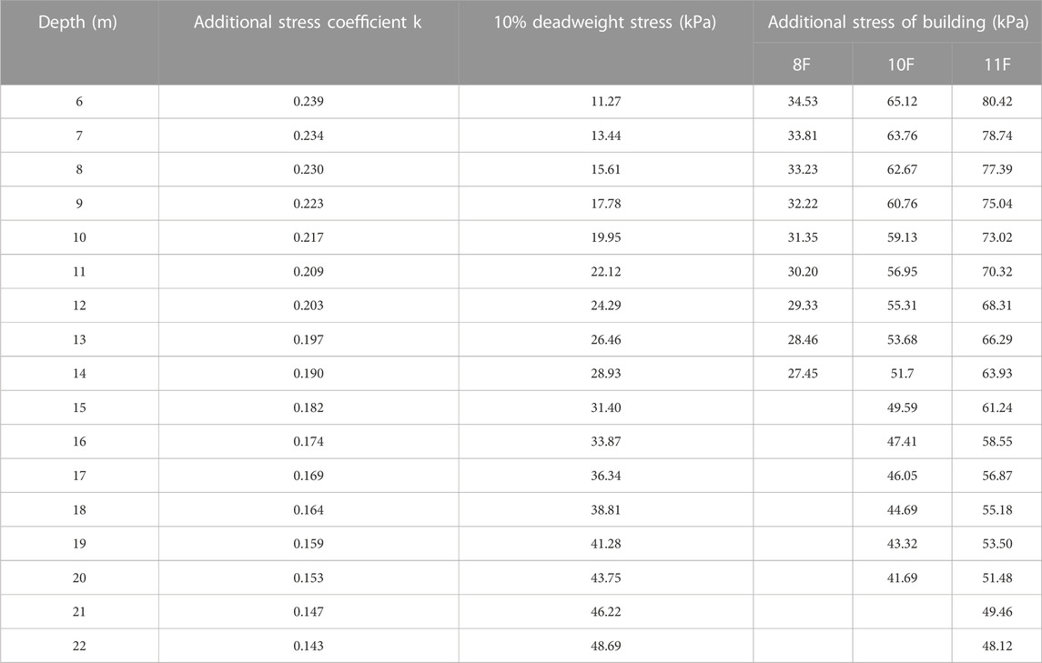
TABLE 1. 10% self-weight stress and additional stress of building corresponding to different depths.
2.3.3 Influence of proposed buildings on stability of overlying strata in old goaf
The relationship between the influence depth of the building load and the developing height of the caving fracture zone exists in three situations, as discussed below and shown in Figure 5.
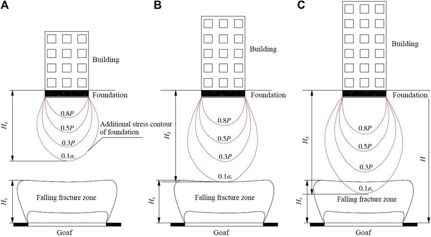
FIGURE 5. Relationship between the influence depth of building load and the development height of caving fracture zone. (A) Stable state. (B) Critical stable state. (C) Unstable state.
First, one of the most important indicators to determine whether activation instability occurs in the goaf is the critical mining depth of the coal seam. The caving fracture zone of the goaf is within the influence range of the additional stress of the building load when the height of the upper roof of the goaf exceeds the critical coal seam mining depth, seriously affecting the stability of goaf State Bureau of Coal Industry (2017). The critical coal seam mining depth H0 is numerically equal to the sum of the additional stress disturbance depth
The maximum development height of the caving fracture zone was calculated above as 42.2 m. The maximum disturbance depth including the additional stress of the 11F building foundation was between 21 and 22 m. The sum of the two is the critical coal seam mining depth, which is approximately 62.2 m.
Second, the drilling depth of the 6010 block was between 43.8 and 44.5 m based on the results of previous drilling and geophysical exploration, and the hole depth was between 44.4 and 45.5 m. After calculation and comparison, the depths of the two goafs under plot 6010 were less than the critical mining depth of a coal seam. Therefore, it was judged that the proposed site was not safe to carry out construction without any safety measures, as it would directly cause the secondary activation of the goaf and affect the stability of the building foundation.
Third, there are different degrees of influence that affect building groups. For example, two small coal mined-out areas that are closely positioned will create a superposition effect on one other (Zhao et al., 2010; Zhao X. et al., 2021). However, the superposition activation effect calculation is very complex. Therefore, it is not accurate to judge the overburden stability of old goaf by only relying on the theoretical calculation results. A numerical simulation method is also needed to verify the theoretical calculation.
3 Results and analysis
3.1 Establishment of numerical model
Midas GTS NX finite element and FLAC3D finite difference are common finite element analysis software packages in the geotechnical field that are suitable for simulating large deformation characteristics of overlying strata movement caused by mining subsidence or new surface buildings (Gao et al., 2016; Tan et al., 2019; Zhao Y. L. et al., 2021). Midas GTS NX 2020 software was first used to establish an engineering geological model for analysis. Subsequently, the mesh model data was imported into the FLAC3D 6.0 software interface to generate a model and ensure the same geological conditions for the two software packages. The consistent use of the same modeling conditions can guarantee the accuracy of numerical simulation.
For rapid modelling, the upper surface of the stratum was considered to be horizontal, the inclination angle of the underlying coal seam was small, horizontal burial was considered, the five strata were considered to be a homogeneous and isotropic continuum, and there was a unified assignment of material parameters.
The size of the plot 6010 geological model was set as length × width × height = 240 × 100 × 65 m. The sizes of the two small coal mine goafs were set to 50 ×18 × 1.8 m and 70 × 16 × 1.8 m. The four 11-story building models were set to 40 × 12 × 32.75 m. The two 10-story building models were set to 40 × 12 × 29.20 m. The two 8-story building models were set to 40 × 12 × 23.90 m. A hybrid grid was used for this modeling to improve the accuracy of the grid division. The total number of grid nodes for the entire model was 71,189 and the total number of units was 71,599. The geometric and mesh models are shown in Figure 6.
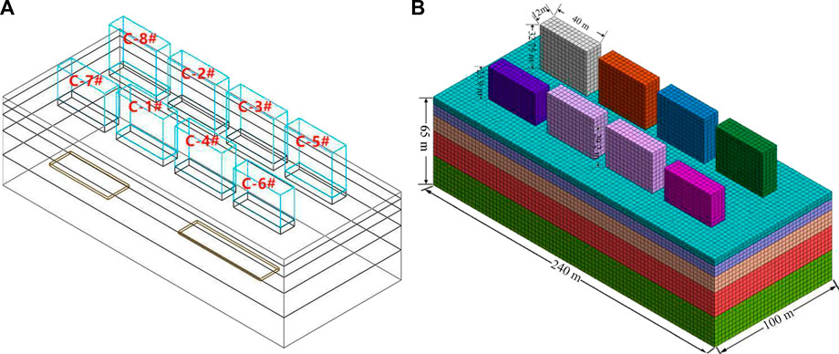
FIGURE 6. The geometric and grid models. (A) Geometric model diagram. (B) Grid model diagram.
The directions of the X and Y axes of the geological model were set as constraint boundaries. The bottom boundary was set to a fully constrained boundary and the top boundary was set to an unconstrained free surface. The initial stress of the model was mainly the self-weight stress of the rock and soil layers. The geological constitutive model in this simulation used the Mohr-Coulomb failure criterion, and the building constitutive model was set to elastic. The physical and mechanical parameters of the rock and soil layer selected by the geological model were consistent with the actual situation to ensure the authenticity of the simulation. Each formation parameter is listed in Table 2.
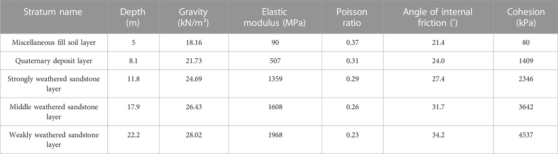
TABLE 2. Physical and mechanical parameters of each rock and soil layer.
3.2 Stability analyzed using midas GTS NX simulation
3.2.1 Characteristics and analysis of surface subsidence displacement and horizontal movement deformation
The grid models of the eight buildings above and four strata below were hidden to observe the displacement and change of the surface under the building load, as shown in Figure 7.
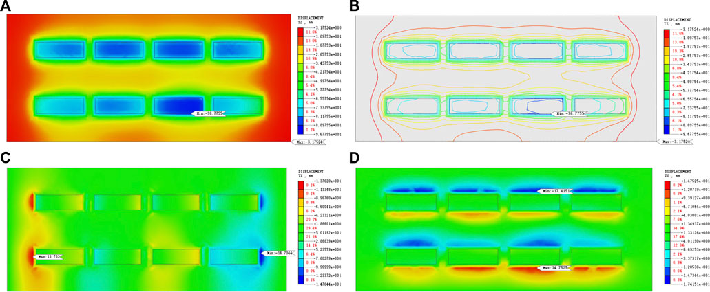
FIGURE 7. Midas GTS NX surface displacement cloud map. (A) Z direction displacement cloud map. (B) Z direction displacement contour map. (C) X direction displacement cloud map. (D) Y direction displacement cloud map.
The Z-direction displacement cloud diagram of the ground in Figure 7A shows that the effect of the building load on the surface subsidence was significant. Eight standard subsidence basins were formed and the vertical displacement value near the C-4# building was the largest at up to 96.8 mm. The closer the ground displacement isolines were to the buildings, the more densely they were divided, as shown in Figure 7B. Additionally, there was distribution around the periphery of the foundation, which extended to the periphery. Cloud color and displacement contours were also approximately symmetrically distributed because the buildings above the 6010 plot were constructed in a symmetrical distribution of location and size.
The building load had little effect on the horizontal movement and deformation of the ground in an east-west direction, as shown in the displacement nephogram of the ground in the X direction in Figure 7C. The maximum horizontal displacement eastward occurred near building C-7# for 13.7 mm. The maximum westward horizontal displacement occurred near building C-6# for 14.7 mm. The X-direction displacements of the C-6# and C-7# buildings with the least floors and smallest loads were the largest. This was due to the fact that two small coal mined-out areas were located directly under the front buildings and the subsidence of the overlying strata in the goaf aggravated the horizontal displacement of the building ground on both sides. The horizontal displacement deformation in the north-south direction exceeded the displacement variation range in the east-west direction, as seen in the Y-direction displacement nephogram of the ground in Figure 7D. The maximum horizontal displacement to the north occurred near building C-4# for 14.8 mm. The largest horizontal displacement to the south occurred near building C-3# for 17.4 mm. The ground with movement deformation in the Y direction was mainly distributed on the front and back sides of the building. However, the north-south displacement of the front building with a lower load generally exceeded that of the back building with a higher load. Therefore, it was inferred that the horizontal movement of the ground was affected by the goaf Li et al. (2016).
3.2.2 Characteristics and analysis of sinking displacement of proposed buildings
The largest sinking point occurred at the top of building C-4#, up to 111.8 mm, as seen in the displacement cloud of the building in the Z direction in Figure 8. The minimum subsidence point occurred at the bottom of building C-6# for 49.9 mm. Four building foundations in the back row far from the goaf were less affected by the goaf. Therefore, the subsidence degree of the building was regularly distributed in the form of large in the middle and small on both sides. The foundation of the front building was closer to the goaf, so it was greatly influenced by the goaf Wang et al. (2015). The area of the right goaf was larger than that of the left goaf. Building C-4# was located directly above the goaf on the right. The largest vertical displacement among the four vertices reached 111.8 mm, the smallest was 98.8 mm, the difference was 13 mm, the overall subsidence degree was relatively large, and uneven settlement was the most serious.
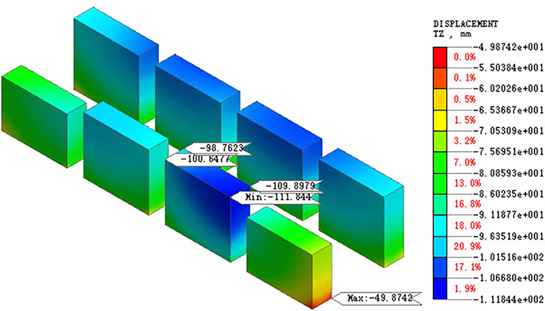
FIGURE 8. Midas GTS NX building displacement cloud map.
3.2.3 Displacement characteristics and analysis of overlying strata in goaf
The influence of goaf on overlying strata was observed by cutting a stratigraphic section. The Z-direction displacement cloud map of the cutting surface of the two goafs is shown in Figure 9.
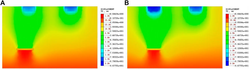
FIGURE 9. Midas GTS NX goaf overburden Z direction displacement cloud map. (A) Left goaf. (B) Right goaf.
The influence depth of the building load overlapped with the development height of the caving fracture zone in the goaf, as shown by the color of the cloud image in Figure 9. Therefore, the building load caused the caving crack zone to develop further, affecting the stability of the overburden and risking the activation of the goaf Luan et al. (2018). The number of building layers arranged on the south side was less than that on the north side because both mined-out areas were located on the south side of the planned site. Despite this, the settlement degree of the foundation and surface of the buildings on the south side also exceeded those on the north side. The maximum settlement of the roof in the left goaf reached 49.2 mm and the floor uplift was approximately 9.7 mm, while the maximum settlement of the roof in the right goaf reached 52.1 mm and the floor uplift was approximately 8.9 mm.
3.3 FLAC3D verifies midas GTS NX simulation results
3.3.1 Characteristics and analysis of surface subsidence displacement and horizontal movement deformation
The Midas GTS NX grid model imported data from the FLAC3D interface generation model and began processing after material properties, boundary conditions, and gravity loads were assigned through command stream editing. Slice processing occurred after model convergence and the displacement changes of the building ground in the Z, X, and Y directions were obtained, as shown in Figure 10.
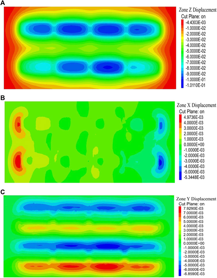
FIGURE 10. FLAC3D surface displacement cloud map. (A) Z direction. (B) X direction. (C) Y direction.
The maximum vertical displacement of the ground surface occurred near the C-4#, C-6#, and C-7# buildings corresponding to the smallest surface subsidence, as shown in Figure 10A. There was a high degree of similarity to the simulated surface Z-direction displacement cloud map, as shown in Figure 12. The subsidence displacement of the FLAC3D surface model reached 101.1 mm, and the surface subsidence displacement only differed by 4.3 mm compared to the MIDAS GTS NX model. Therefore, the results of FLAC3D modeling were approximately the same as those of MIDAS GTS NX modeling. The movement and deformation of the building ground in the east-west and north-south directions were not large, as shown in Figures 10B,C, respectively. The maximum east-west and north-south displacements were 5.3 and 7.9 mm, respectively. The difference with the MIDAS GTS NX software simulation results was almost doubled, but the difference between the maximum displacements was only approximately 9.5 mm, which had little effect on the safety and stability of the buildings.
3.3.2 Characteristics and analysis of sinking displacement of proposed buildings
The Z-direction displacement changes of eight building models in FLAC3D are shown in Figure 11. The maximum and minimum subsidence values were 119.4 and 45.1 mm, respectively. These are slightly larger than the maximum sinking value (by 7.6 mm) and slightly smaller than the minimum sinking value (by 4.7 mm) when compared with the Z-direction displacement value of the MIDAS GTS NX building, as shown in Figure 8. The phenomenon of cloud image stratification was more obvious due to the dead weight of the building. In addition, the color of the C-2# and C-3# building displacement cloud images of the 11F building gradually deepened from bottom to top. Similarly, the 11F C-5# and C-8# building displacement cloud colors showed that the inner color was heavier and the outer color was lighter. This was because the subsidence degree of the building foundation in the middle exceeded those of the building foundation on both sides. Additionally, the settlement of buildings on both sides to the central direction was larger, which was the main reason for the uneven settlement of the buildings. The color difference was significant between the C-1# and C-4# building displacement cloud images of the same 10 floors. The main reason for this was that the existence of a small coal mined-out area increased the subsidence of the overlying strata. Subsequently, the uneven settlement of buildings was more obvious and it was further inferred that the underlying goaf had affected the normal use of the building Tan et al. (2020).
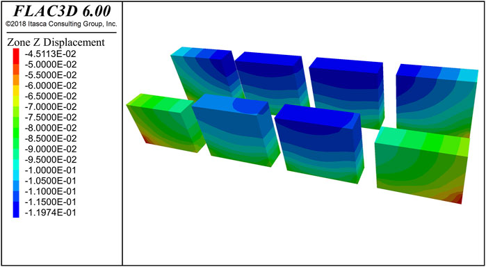
FIGURE 11. FLAC3D building displacement cloud map.
3.3.3 Displacement characteristics and analysis of overlying strata in goaf
The Z-direction displacement cloud diagram of the overlying rock cutting surface of the two goaf areas in the FLAC3D model is shown in Figure 12. The color of the overburden cloud of the goaf clearly shows that the influence depth of the building load reached the development height of the caving crack zone, the maximum settlement of the two goaf rooves was approximately 50 mm, the uplift of the bottom plate was approximately 10 mm, there was little difference between the overburden displacement value of the goaf and that simulated by the MIDAS GTS NX software, and the cloud image color distribution was approximately the same. Two numerical simulation methods were used to verify one other and the results were very close, which ensured the accuracy of the stability analysis of goaf.
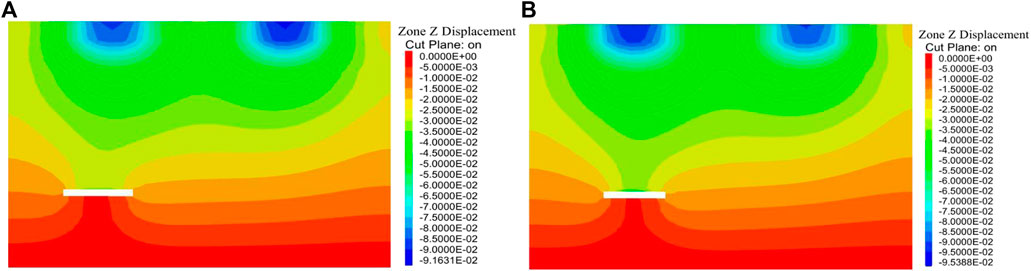
FIGURE 12. FLAC3D goaf overburden displacement cloud map. (A) Left goaf. (B) Right goaf.
It can be inferred from the results of the two numerical simulation software packages that the influence range of the old goaf was far greater than the mining range if the mined-out area was not treated in time. Therefore, if a building is constructed here, it will affect the stability of the overlying strata and exacerbate the uneven settlement of the building. There may even be a building collapse, which would seriously affect the safety of people and property Sun et al. (2022).
4 Discussion
4.1 Evaluation of goaf treatment effect
It was determined that the mined-out area of a small coal kiln risked activation under the action of a building load through theoretical calculation and numerical simulation studies, which affected the safety and stability of the upper engineering construction. Therefore, the old goaf should be treated before construction. This study combined the basic caving, filling, supporting, and closed isolation methods to develop a diversified goaf management technology to deal with goaf Chen et al. (2016). The filling method was chosen to strengthen the underlying small coal mined-out area and was combined with a practical engineering background, geological conditions, and occurrence form of the goaf. The collaborative deformation of the grouting filling body and surrounding rock had a very good effect, effectively limiting the movement of the overlying strata change. This approach improved the stability of the building foundation and solved the problem of disposing of a great deal of production waste, which is conducive to sustainable development.
4.2 Detection of goaf treatment effect
4.2.1 Unconfined compressive strength test of filling body
A hole was drilled three months after the completion of the grouting. There was a little water leakage during drilling but there was no drill bit falling phenomenon, which indicated that there were no interconnected holes in the goaf and it had a high filling rate and a good combination of filling body and original rock mass. An unconfined compressive strength test was conducted after the core was polished to inspect the filling grouting effect. The results showed that the unconfined compressive strength of the filling body was above 2 MPa, which meets the technical specifications for the foundation treatment of goaf buildings Wang et al. (2021).
4.2.2 Stability analysis after filling treatment
After the grouting and filling treatment of the goaf, Midas GTS NX was used to analyze the moving deformation of the surface, buildings, and goaf roof compared with the displacement results before governance, as shown in Figure 13.
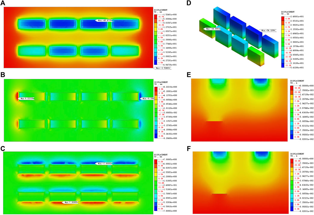
FIGURE 13. Displacement change cloud map after treatment. (A) Z direction surface. (B) X direction surface. (C) Y direction surface. (D) Z direction building. (E) Z direction left goaf. (F) Z direction right goaf.
The grouting filling treatment of the mined-out area effectively reduced the displacement value of the whole geological model under a building load, the movements of the ground and building itself were reduced to approximately half that of the original value, and the rest of the displacement was caused by the weight of the building itself. The most obvious displacement change was the settlement value of the goaf roof, from 52.1 mm before filling to 20.4 mm after filling. The effect of governance was remarkable, avoiding the activation of the old goaf under a building load. This will ensure the safety and stability of building foundations and the overlying strata in the goaf Ao et al. (2017).
5 Conclusion
This study comprehensively analyzed the safety and stability of an old goaf under construction engineering based on specific projects and using a variety of research methods.
(1) Exploration of the planned land was conducted by drilling holes and using geophysical exploration techniques. The stratigraphic characteristics of the study area and occurrence form of the goaf were determined.
(2) According to theoretical analysis, the developing height of the caving fracture zone in the old goaf was approximately 42.2 m, and the maximum depth of the additional stress disturbance of the building foundation was approximately 20 m. The two mined-out areas below the planned site were located approximately 45 m underground, which was significantly less than the coal mining depth. Therefore, the theoretical analysis demonstrated that there was a risk of activation in the goaf.
(3) Midas GTS NX and FLAC3D software packages were used for the numerical simulation of the geological structures and buildings of planned sites. The simulation results of the two software were similar, with uneven subsidence of approximately 100 mm occurring in the buildings and ground surface. Additionally, the goaf roof demonstrated subsidence of approximately 50 mm. This may cause the overlying strata to break up or a small range of rockfall to collapse because the stability of the surrounding rock and building foundation would be affected.
(4) Finally, reinforcement treatment of a small coal mine goaf was conducted using the proposed grouting filling method, and the strength and filling rate of the filling body met engineering standards. It was confirmed through a numerical simulation comparison that the displacement changes of the surface, building, and surrounding rock were effectively reduced after filling, ensuring the safety and stability of the building foundation. The research findings have significant reference and application values for similar mining cities to rationally use lands above the old goaf to construct buildings.
Data availability statement
The original contributions presented in the study are included in the article/Supplementary Material, further inquiries can be directed to the corresponding author.
Author contributions
XZ and WL wrote the main manuscripts and established numerical models. TL and ZL provided research ideas and overall control of manuscript text. GC, ZS, and RL provided engineering reference materials and analyzed simulated data. All authors reviewed the manuscript.
Funding
This study was supported by the National Natural Science Foundation of China (Grant Nos. 51774166).
Conflict of interest
Author GC, ZS and RL were employed by Beijing Jingneng Geological Engineering Co., Ltd.
The remaining authors declare that the research was conducted in the absence of any commercial or financial relationships that could be construed as a potential conflict of interest.
Publisher’s note
All claims expressed in this article are solely those of the authors and do not necessarily represent those of their affiliated organizations, or those of the publisher, the editors and the reviewers. Any product that may be evaluated in this article, or claim that may be made by its manufacturer, is not guaranteed or endorsed by the publisher.
Supplementary material
The Supplementary Material for this article can be found online at: https://www.frontiersin.org/articles/10.3389/feart.2023.1063684/full#supplementary-material
References
Abedi, M., and Norouzi, G. H. (2012). Integration of various geophysical data with geological and geochemical data to determine additional drilling for copper exploration. J. Appl. Geophys. 83, 35–45. doi:10.1016/j.jappgeo.2012.05.003
Ao, X. F., Wang, X. L., Zhu, X. B., Zhou, Z. Y., and Zhang, X. X. (2017). Grouting simulation and stability analysis of coal mine goaf considering hydromechanical coupling. J. Comput. Civ. Eng. 31 (3), 04016069. doi:10.1061/(asce)cp.1943-5487.0000640
Chen, G. F., Luo, C. F., Zhong, L. X., and Chen, F. (2019). Stability analysis and treatment scheme selection of goaf based on Rhino-FLAC ∼(3D). Min. Res. Dev. 39 (09), 30–35. doi:10.13827/j.cnki.kyyk.2019.09.007
Chen, S. J., Yin, D. W., Cao, F. W., Liu, Y., and Ren, K. Q. (2016). An overview of integrated surface subsidence-reducing technology in mining areas of China. Nat. Hazards. 81 (2), 1129–1145. doi:10.1007/s11069-015-2123-x
Chen, S. J., Zhang, L. B., Jiang, N., Yin, D. W., Gao, Z. W., Guo, W. J., et al. (2022). A large - scale project construction case above the old mined-out area of a coal mine in Shandong. J. Coal Sci. Eng. (China) 47 (03), 1017–1030. doi:10.13225/j.cnki.jccs.xr21.1687
Gao, F. Q., Stead, D., Kang, H. P., and Wu, Y. Z. (2014). Discrete element modelling of deformation and damage of a roadway driven along an unstable goaf—A case study. Int. J. Coal Geol. 127, 100–110. doi:10.1016/j.coal.2014.02.010
Gao, X. Q., Zhang, D., Absai, V., Feng, H. B., and Yi, J. J. (2016). Computational simulation of coupled geodynamics for forming the Makeng deposit in Fujian Province, China: Constraints of mechanics, thermotics and hydrology. J. Geochem. Explor. 160, 31–43. doi:10.1016/j.gexplo.2015.10.010
Gao, Z. G., Jin, B., Yan, F., Chen, Y. Q., He, H. S., and Liu, H. B. (2022). Exploration and stability analysis of mined-out area of small kiln in the construction site of Mentougou new city, Beijing. J. Mineral Explor. 13 (07), 975–982. doi:10.20008/j.kckc.202207011
Guo, Q. B., Meng, X. R., Li, Y. M., Lv, X., and Liu, C. (2021). A prediction model for the surface residual subsidence in an abandoned goaf for sustainable development of resource-exhausted cities. J. Clean. Prod. 279, 123803. doi:10.1016/j.jclepro.2020.123803
Jia, H. W., Yan, B. X., Guan, K., Liu, H. L., Wu, Q. Z., Yin, Y. T., et al. (2022). Stability analysis of shallow goaf based on field monitoring and numerical simulation: A case study at an open-pit iron mine, China. Front. Earth Sci. 10, 897779. doi:10.3389/feart.2022.897779
Li, L., Wu, K., and Zhou, D. W. (2016). Evaluation theory and application of foundation stability of new buildings over an old goaf using longwall mining technology. Environ. Earth Sci. 75, 763. doi:10.1007/s12665-016-5574-9
Li, Q., Ma, D., Zhang, Y. D., Liu, Y., and Ma, Y. J. (2022). Insights into controlling factors of pore structure and hydraulic properties of broken rock mass in a geothermal reservoir. Lithosphere 2021 (5), 3887832. doi:10.2113/2022/3887832
Liu, S. J. (2017). Stability evaluation of high-rise buildings above old goaf. China Coal 43 (09), 68–72. doi:10.19880/j.cnki.ccm.2017.09.014
Liu, X. S., Tan, Y. L., Ning, J. G., Tian, C. L., and Wang, J. (2015). The height of water-conducting fractured zones in longwall mining of shallow coal seams. Geotech. Geol. Eng. 33 (3), 693–700. doi:10.1007/s10706-015-9851-2
Luan, H. J., Lin, H. L., Jiang, Y. J., Wang, Y. H., Liu, J. K., and Wang, P. (2018). Risks induced by room mining goaf and their assessment: A case study in the shenfu-dongsheng mining area. Sustainability 10 (3), 631. doi:10.3390/su10030631
Ma, D., Duan, H. Y., Zhang, J. X., Liu, X. W., and Li, Z. H. (2022b). Numerical simulation of water–silt inrush hazard of fault rock: A three-phase flow model. Rock Mech. Rock Eng. 55, 5163–5182. doi:10.1007/s00603-022-02878-9
Ma, D., Duan, H. Y., and Zhang, J. Y. (2022a). Solid grain migration on hydraulic properties of fault rocks in underground mining tunnel: Radial seepage experiments and verification of permeability prediction. Tunn. Undergr. Space Technol. 126, 104525. doi:10.1016/j.tust.2022.104525
Nazarimofrad, E., and Barkhordar, A. (2016). Buckling analysis of orthotropic rectangular plate resting on Pasternak elastic foundation under biaxial in-plane loading. Mech. Adv. Mater. Struct. 23 (10), 1144–1148. doi:10.1080/15376494.2015.1059528
Olabode, O. P., San, L. H., and Ramli, M. H. (2020). Analysis of geotechnical-assisted 2-D electrical resistivity tomography monitoring of slope instability in residual soil of weathered granitic basement. Front. Earth Sci. 8, 580230. doi:10.3389/feart.2020.580230
Ren, L. W., He, P. F., Zou, Y. F., Yang, C., Dun, Z. L., Zou, Z. S., et al. (2022). A novel evaluation method of mining goaf ground activation under high-speed railway load. Front. Earth Sci. 10, 931466. doi:10.3389/feart.2022.931466
Shi, H., Zhang, Y. B., and Tang, L. (2021). Physical test of fracture development in the overburden strata above the goaf and diffusion process of permeable grout slurry. Bull. Eng. Geol. Environ. 80, 4791–4802. doi:10.1007/s10064-021-02189-3
State Bureau of Coal Industry (2017). Code for coal pillar retention and coal mining in buildings, water bodies, rail-ways and main roadways. Beijing: Coal Industry Press.
Sun, Y., Bi, R., Sun, J., Zhang, J., Taherdangkoo, R., Huang, J., et al. (2022). Stability of roadway along hard roof goaf by stress relief technique in deep mines: A theoretical, numerical and field study. Geomechanics Geophys. Geo-Energy Geo-Resources 8 (2), 45–16. doi:10.1007/s40948-022-00356-8
Tan, Y. L., Guo, W. Y., Xin, H. Q., Zhao, T. B., Yu, F. H., and Liu, X. S. (2019). Research on key technology of rock burst monitoring in deep mining of coal mine. J. China Coal Soc. 44 (01), 160–172. doi:10.13225/j.cnki.jccs.2019.5088
Tan, Y. L., Guo, W. Y., Zhao, T. B., and Meng, X. J. (2020). Study on the mechanism of induced shock induced by instability of deep coal roadway and "unloading - solid" cooperative control. J. China Coal Soc. 45 (01), 66–81. doi:10.13225/j.cnki.jccs.YG19.1772
Wang, F. T., Zhang, C., Zhang, X. J., and Song, Q. (2015). Overlying strata movement rules and safety mining technology for the shallow depth seam proximity beneath a room mining goaf. Int. J. Min. Sci. Technol. 25 (1), 139–143. doi:10.1016/j.ijmst.2014.12.007
Wang, J. A., Li, D. Z., and Shang, X. C. (2012). Creep failure of roof stratum above mined-out area. Rock Mech. rock Eng. 45 (4), 533–546. doi:10.1007/s00603-011-0216-8
Wang, J. Q., Zhang, Q., Yin, W., Qi, S. M., Gao, D., and Ma, D. (2021). On-site measurement on compaction characteristics of coal gangue and surface subsidence disaster in deep backfilling mining. Front. Earth Sci. 9, 724476. doi:10.3389/feart.2021.724476
Xiao, C., Zheng, H. C., Hou, X. L., and Zhang, X. J. (2015). A stability study of goaf based on mechanical properties degradation of rock caused by rheological and disturbing loads. Int. J. Min. Sci. Technol. 25 (5), 741–747. doi:10.1016/j.ijmst.2015.07.007
Xu, P., Mao, X. B., Zhang, M. X., Zhou, Y. J., and Yu, B. Y. (2014). Safety analysis of building foundations over old goaf under additional stress from building load and seismic actions. Int. J. Min. Sci. Technol. 24 (5), 713–718. doi:10.1016/j.ijmst.2014.03.030
Yang, Z., Lv, Y. Q., and Sun, G. K. (2020). Influence of mined-out area of multiple coal seams on stability of proposed upper building. J. Xian Univ. Sci. Technol. 40 (05), 862–868. doi:10.13800/j.cnki.xakjdxxb.2020.0515
Yasitli, N. E., and Unver, B. (2005). 3D numerical modeling of longwall mining with top-coal caving. Int. J. Rock Mech. Min. Sci. 42 (2), 219–235. doi:10.1016/j.ijrmms.2004.08.007
Zhang, C. R., Yang, X. C., Ren, G. R., Ke, B., and Song, Z. L. (2019). Instability of gypsum mining goaf under the influence of typical faults. IEEE Access 7, 88635–88642. doi:10.1109/access.2019.29258102019.2925810
Zhao, X., Liu, D. S., Li, S. L., Wang, M., Tian, S. K., Niu, X. M., et al. (2021). A method for determining the thicknesses of the reserved protective layers in complex goafs using a joint-modeling method of GTS and Flac3D. Adv. Civ. Eng. 2021, 1–18. doi:10.1155/2021/8862339
Zhao, Y. L., Liu, Q., Liu, H., Liao, J., Chang, L., Tan, T., et al. (2021). Triaxial compression and acoustic emission test and compression shear fracture model of single fracture limestone under water-force coupling. J. China. Coal. Soc. 46 (12), 3855–3868. doi:10.13225/j.cnki.jccs.2021.0367
Zhao, Y. L., Peng, Q. Y., Wan, W., Wang, W. J., and Chen, B. (2014). Fluid–solid coupling analysis of rock pillar stability for concealed karst cave ahead of a roadway based on catastrophic theory. Int. J. Min. Sci. Technol. 24 (6), 737–745. doi:10.1016/j.ijmst.2014.10.002
Zhao, Y. L., Wu, Q. H., Wang, W. J., Wan, W., and Zhao, F. J. (2010). Stability intensity reduction method of overlapping roof in goaf based on catastrophe theory and its application. Chin. J. Rock Mech. Eng. 07, 1424–1434.
Zhu, W. B., Xu, J. M., Xu, J. L., Chen, D. Y., and Shi, J. X. (2017). Pier-column backfill mining technology for controlling surface subsidence. Int. J. Rock Mech. Min. Sci. 96, 58–65. doi:10.1016/j.ijrmms.2017.04.014
Keywords: engineering drilling, geophysical exploration, theoretical analysis, numerical simulation, building foundation stability
Citation: Zhang X, Li W, Li T, Li Z, Cai G, Shen Z and Li R (2023) Stability analysis and numerical simulation of foundation in old goaf under building load. Front. Earth Sci. 11:1063684. doi: 10.3389/feart.2023.1063684
Received: 07 October 2022; Accepted: 05 January 2023;
Published: 17 January 2023.
Edited by:
Johan Wesseloo, University of Western Australia, AustraliaReviewed by:
Dan Ma, China University of Mining and Technology, ChinaYoujun Ning, Southwest Petroleum University, China
Copyright © 2023 Zhang, Li, Li, Li, Cai, Shen and Li. This is an open-access article distributed under the terms of the Creative Commons Attribution License (CC BY). The use, distribution or reproduction in other forums is permitted, provided the original author(s) and the copyright owner(s) are credited and that the original publication in this journal is cited, in accordance with accepted academic practice. No use, distribution or reproduction is permitted which does not comply with these terms.
*Correspondence: Wenliang Li, lwl211322@163.com