Abstract
In the running process of high power motor, the shaft voltage and bearing current are sometimes present. Under the combined action of the current and the mechanical load, the corrugated groove is formed on the bearing race. The paper analyzed the causes, forms and characteristics of the early current damage of bearing, studied the relationship between the number of shaft current size and bearing pitting attack damage, presented the theoretical calculation method of the corrugated groove, got the change rule of the corrugated groove spacing with the change of the motor speed and the mechanical load. The experimental results are in agreement with the theoretical analysis, the measurement value of corrugated groove average spacing is very close to its theoretical value, and the average deviation is less than 10 %.
1. Introduction
Bearing damage generally have three ways that thermal damage, force damage and electrical damage. According to the literature statistics [1], 25 % of the bearing damage is caused by the current. Current research on current mostly from the actual production, and summarize the cause, harm and suppressive measures of current [2-5]. Some scholars have studied the mechanism of shaft voltage and current for specific generators and motors. Zika Thomas analyzed the causes and effects of parasitic currents in asynchronous motors, and discussed the latest research results on the general electrical performance and bearing damage of bearings [6]. William Liu et al. analyzed the EDM, wrinkling and its characterization methods caused by bearing current [7]. A. Picot think that high frequency current through the bearings lead to premature failure of the bearing, proposed the Welch cycle statistical method based on a stator current [8]. However, there are few studies on the damage mechanism, damage form and rule of bearing current, and for high-power motors such as wind turbines, bearing current damage has become the main form of mechanical damage, which needs to be studied deeply.
2. Early current damage analysis of motor bearings
Considering the electrical characteristics of the bearing, the pitting caused by current damage is related to the size of the current, voltage threshold of the oil film and the Hertz contact area. The relationship between the bearing equivalent resistance [9] and the number of pitting is shown in Eq. (1):
According to the physical relationship among the voltage threshold of the bearing lubricating oil film, the equivalent resistance of the bearing and the bearing current , the number of the pitting of bearing current damage can be inferred from Eq. (2):
where the is shown in Eq. (3):
Assume that the motor speed is 1500 rpm, electrical conductivity is 1.0×10⁻⁷ Ω·m, the voltage threshold of breakdown oil film is 5 , bearing contact type parameter is point contact, 0.5 [10]. When bearing type is selected 6205EKA, we can obtain the Hertz contact area according to the calculation references [11], the contact area on the inner raceway is 1.17 mm2 and the contact area on the outer raceway is 1.53 mm2. Substituting these parameters into Eq. (2), the number of the damage pitting on bearing raceway varies with the magnitude of current which can be obtained as shown in Fig. 1.
Fig. 1Relationship between the number of damage pitting and bearing current
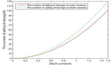
From Fig. 1, it can be seen that the number of pitting on the bearing race increases as the number of current bearing discharges increases, and the number of pitting on the inner race is relatively large. As the motor runs for a long time and the constant action of load, the bearing’s lubricating oil film will gradually be destroyed and the electrochemical corrosion of the bearing race surface will continue to intensify, which may eventually result in mechanical damage and failure of the bearing.
3. Spacing calculation and analysis of corrugated groove on the bearing raceway
From microscopic perspective, in the machining process about bearings, due to change in the vibration frequency of the machine, the bearings have a certain degree of waviness. The waviness of the bearing race surface will affect the thickness of the bearing oil film [12], the corrugated part of the oil film will become thinner, when the shaft voltage breakthrough film threshold voltage, the bearing current will be generated. At the same time, because the rolling elements have a certain axial oscillation, the waviness will continue to expand along the width of the raceway, the constant action of the current and mechanical load on the bearing raceway, finally, washboard corrugated groove will be formed on the surface of bearing’s raceway.
According to reference [13-17], the bearing corrugated spacing is related to the magnitude and frequency of current discharge, the number of rolling elements on the load area, the rotary frequency and relative size parameters of bearings. the spacing of corrugated groove and on the bearing inner raceway and outer ring raceway can be expressed by the number of similar corrugated grooves and and the length of the corrugated groove are and on the raceway, which is as shown in Eq. (4):
In the rotation of the motor bearing, you can describe the corrugated spacing by using arc length of raceway in the bearing load area of rolling elements with every rotation. Because the rolling elements and the raceway closely interact with each other, , , , are:
here, is the coefficient of bearing [14], 1 for deep groove ball bearings; is the number of rolling elements; is the number of loading position, 1 when load is only radial; the rotary frequency of rolling elements :
Substituting Eq. (5), Eq. (6) and Eq. (7) into Eq. (4), the spacing of corrugated groove and on the bearing inner and outer raceway are as shown in Eq. (8):
If the motor bearing type is 6205EKA deep groove ball bearings, the motor speed range change in the range of 1200-1800 rpm, we can get the distribution of corrugated grooves on the bearing raceway. As shown in Fig. 2, when the load of the motor is constant, the spacing of corrugated groove decreases gradually with the increase of the motor speed, and when the speed of the motor is constant, this spacing decrease with the increase of the load. In either case, corrugation spacing on the outer raceway is greater than the spacing on the inner raceway, which is due to the Hertz contact area on outer raceway is relatively large. Contact area is large, the number of corrugations on the raceway is small, so the ripple spacing is large.
Fig. 3The spacing of corrugated groove change rule with the rotary speed and radial load of motor
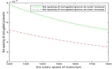
a) The rotary speed
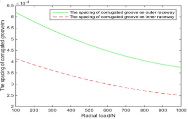
b) Radial load of motor
4. Experiment on damage mechanism of bearing current
The simulation test device is shown in Fig. 4, device is driven by variable frequency motor, rotating spindle and motor selection are connected by an insulated coupling, the spindle is supported by ceramic bearings, circuit loop is formed among DC switching power, ring carbon brush and test bearing, the bearing current is generated and switched by controlling the DC switching power supply voltage. In Fig. 5, the bearing has a pitting damage on the inner race Fig. 5(a) and outer race Fig. 5(b) after 10 hours of mechanical load and bearing current, and after 50 hours, evolve into corrugated groove in Fig. 6.
Fig. 4Bearing current damage test device: 1 – motor, 2 – coupling, 3 – bearing support, 4 – carbon brush, 5 – test bearing, 6 – loading device, 7 – shaft, 8 – insulated ceramic bearings, 9 – DC switching power, 10 – carbon brush support, 11 – base
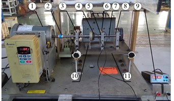
Fig. 5The result of current damage after 10 hours
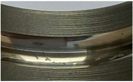
a) Outer race
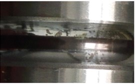
b) Inner race
Fig. 6The result of current damage after 50 hours
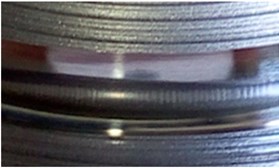
a) Outer race
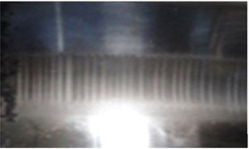
b) Inner race
Table 1Compared with the measured average and theoretical calculated values which are the corrugated spacing on the bearing outer and inner race
Operating conditions | Theoretical values / mm | Measured average values / mm | The deviation ratio between theoretical and measured average value | |||||
Inner race | Outer race | Inner race | Outer race | Inner race | Outer race | |||
The rotary speed of motor / rpm | 1200 | 3 | 0.528 | 0.719 | 0.565 | 0.751 | 3.3 % | 2.1 % |
1500 | 3 | 0.436 | 0.625 | 0.523 | 0.675 | 8.3 % | 3.7 % | |
1800 | 3 | 0.352 | 0.532 | 0.422 | 0.582 | 8.3 % | 5.6 % | |
Radial load / N | 100 | 3 | 0.428 | 0.503 | 0.495 | 0.568 | 6.8 % | 5.7 % |
500 | 4 | 0.335 | 0.475 | 0.408 | 0.541 | 8.9 % | 6.7 % | |
1000 | 5 | 0.242 | 0.369 | 0.314 | 0.455 | 10 % | 9.5 % | |
Table 1 shows the damage results of the bearing after running 50 hours under the combined action of load and shaft current. The main purpose is to analysis corrugated spacing on the bearing outer and inner race. It is seen from Table 1 that average deviation of spacing of the corrugated groove between actual measured values and theoretical calculated values are less than 10 %, average deviation of inner raceway is from 3.3 % to 10 %, average deviation of outer raceway is from 2.1 % to 9.5 %. Where in different rotary speed of motor, average deviation of inner raceway is from 3.3 % to 8.3 %, average deviation of outer raceway is from 2.1 % to 5.6 %, the average deviation of the inner ring is larger by comparing them, and the average deviation is greatest at rated speed. In different radial load, average deviation of inner raceway is from 6.8 % to 10 %, average deviation of outer raceway is from 5.7 % to 9.5 %, the average deviation of the inner ring is also larger by comparing them, And the larger the load, the greater the average deviation. Compared with the rotary speed of motor and the radial load, the load has a greater impact on its deviation, indicating that the mechanical load has greater impact on the bearing current damage.
5. Conclusions
This paper studies the current damage mechanism of high power motor bearings, deduces the theoretical calculation formula of the spacing of corrugated grooves, finds the damage form and evolution rule of the bearing current under different working conditions, and experiment verifies the theoretical analysis result.
References
-
Macdonakl Don, Gray Will PWM drive related bearing failures. IEEE Industry Applications Magazine, 1999, p. 41-47.
-
Zheng Haibo Case study on vibration monitoring of wind turbine. Wind Energy, Vol. 7, Issue 7, 2014, p. 88-92.
-
Muetze A. Bearing Currents in Inverter-Fed AC-Motor. Techische Universitaet Darmstadt, Germany, 2004.
-
Chen Guoqiang, Chen Guozhong, Xu Ming Wind turbine generator shaft voltage and current on the bearing and preventive measures. Shenhua Technology, Vol. 12, Issue 5, 2014, p. 60-62.
-
Qin Lijian Practical Manual for the Design, Operation, Maintenance and Standard Specification of New Technologies and Power Generation Projects for Wind Power Generation. China Science and Technology Culture Press, Beijing, 2005, p. 4-14.
-
Zika Thomas, Buschbeck Frank, Preisinger Gerw, et al. Current passage through bearings in wind turbine generators. Motor Control and Application, Vol. 35, Issue 9, 2008, p. 15-19.
-
Liu William The prevalent motor bearing premature failures due to the high frequency electric current passage. Engineering Failure Analysis, Vol. 45, Issue 10, 2014, p. 118-127.
-
Picot A., Obeid Z., Régnier J., et al. Statistic-based spectral indicator for bearing fault detection in permanent-magnet synchronous machines using the stator current. Mechanical Systems and Signal Processing, Vol. 46, Issue 2, 2014, p. 424-441.
-
Liu Ruifang, Lou Zhuofu, Ma Xiping Modeling of bearing capacitance and resistance in motor bearing current problems. Proceedings of the CSEE, Vol. 15, Issue 15, 2014, p. 2430-2437.
-
Tripp J. H., Garte S. The gas-tightness of separable base metal electric contacts. IEEE Transactions on Components Hybrids and Manufacturing Technology, Vol. 4, Issue 1, 1981, p. 85-92.
-
Busse D., Erdman J., Kerkman R. J., et al. The effects of PWM voltage source inverters on the mechanical performance of rolling bearings. 11th Annual Applied Power Electronics Conference and Exposition, Vol. 2, 1996, p. 561-569.
-
Ren Zhiqiang, Guo Feng, Wang Jing Measurement and simulation of the oil film in a thrust ball bearing considering the waviness on its raceway. Tribology, Vol. 33, Issue 6, 2013, p. 586-593.
-
Sayles R. S., Poon S. Y. Surface topography and rolling element vibration. Precision Engineering, Vol. 3, Issue 3, 1981, p. 137-144.
-
Prashad H. Theoretical and experimental investigations on the pitch and width of corrugations on the surfaces of ball bearings. Wear, Vol. 143, Issue 1, 1991, p. 1-14.
-
Harris T. A. Rolling bearing analysis. Journal of Tribology, Vol. 108, Issue 1, 1984.
-
Har Prashad Determination of time span for the appearance of flutes on the track surface of rolling-element bearings under the influence of electric current. Tribology Transactions, Vol. 41, Issue 1, 1998, p. 103-109.
-
Busse D., Erdman J., Kerkman R. J., et al. Bearing currents and their relationship to PWM drives. IEEE Transactions on Power Electronics, Vol. 12, Issue 2, 1997, p. 243-252.
About this article

Financial support from National Natural Science Foundation of China (51575178, 11572125) are appreciated.
