Abstract
In quadruped robot locomotion using parallel mechanisms, researchers have used equal link lengths as legs for walking. However, force requirements are not the same in the forward and return strokes. An unsymmetrical parallel mechanism can be considered to accommodate such requirements. This work presents optimized dimensions of a 5R planar parallel mechanism (5R-PPM) with two degrees of freedom (DoF). Optimized dimensions are determined by formulating an optimization problem using kinematics and dynamics equations for the 5R-PPM. Genetic algorithm is considered to obtain solutions for the optimization problem formulated in this study. The constraint condition expressed here for optimization will attempt to minimize the peak torque essential to displace the links in the mechanism for the given height of the robot body and the path to be traced by the end-effector. After analysing all the four possible working modes for the same end-effector movement, the best working mode is selected for the quadruped legs. The equations are formulated and solved in MATLAB, and validated in the MATLAB Simscape Multibody toolbox.
1. Introduction
Mechanisms used in robots are highly inspired by locomotion in humans and animals. Most robots have open-loop mechanisms or serial mechanisms that have larger workspaces and dexterity than closed-chain mechanisms [1]. However, it is believed that the closed-chain or parallel mechanisms are innately more accurate than their counterpart, i.e. in parallel link mechanisms, their errors get averaged rather than getting added cumulatively [2]. In an open-chain mechanism, accurately placing the end effector is slightly compromised, with low stiffness, and a notable amount of actuator power getting wasted, thus decreasing the dynamic performance. Owing to these predominant shortcomings, many engineering tasks requiring an excellent positional accuracy of end-effector are not implemented using serially connected mechanisms.
Therefore, two DoF 5R-PPMs have been comprehensively studied in literature using analytical methods [3-7]. The 5R-PPM is prone to singularities, and thus, the control and trajectory planning are more involved. The most critical issue for the parallel mechanism is to avoid singularity due to control uncertainty that manifests in poor force transmission [5].
Several researchers have worked towards increasing the workspace of parallel mechanism [8-12]. By using parallel mechanisms as manipulators, users were able to achieve higher accuracy, payload carrying capacity and stiffness. Another interesting research suggested using redundant actuators to increase the workspace of a 5R-PPM, but with the disadvantage of significantly increased cost [13]. As parallel mechanisms are susceptible to singularities, the complete workspace covered by a parallel mechanism is not available for use. While moving from one region to another, the mechanism will lose a DoF which could be catastrophic. Many researchers have done comprehensive research on the analysis of singularities [6, 14-18]. Generally, in parallel mechanisms, two singularity types are witnessed: Type-1 & Type-2 [4]. One or more DoF are compromised in Type-1 singularity. While in Type-2 singularity, at the end-effector, any force applied will not be resisted by the actuator. Although conventional solutions addressing these issues were discussed thoroughly in literature, not all scenarios were covered, and the solutions provided are only applicable to a few cases [11, 19-22].
Precise motion is required in most cases, and thus, all singularities appearing in the path should be avoided. Nevertheless, when solving parallel mechanisms’ inverse kinematics problem, we obtain multiple solutions, but using suitable criteria, the best solution could be opted [8,15].
Another study suggested that the ‘’ working mode should be used for optimizing the 5R-PPM [23]. However, no rational reason was provided for this statement as to what are the disadvantages of choosing other working modes, or are there any scenarios where the remaining working modes could be used, or is there any significant achievement by selecting the ‘’ working mode. Here, a study in the design optimization for the 5R-PPM is presented. Dimension synthesis is achieved by optimizing five parameters of the mechanism while minimizing the peak actuator torque. Actuator contributes to a major portion of the cost of the robot, and thus, it needs to be optimally sized for cost savings. The modes of interest in 5R-PPM are assembly modes, related to the forward kinematics, and working modes associated with the inverse kinematics. Here, the working modes of the parallel mechanism are thoroughly studied.
In this study, computational tools such as MATLAB and MATLAB Simscape Multibody toolbox are used. The advantage of the numerical approach lies in simulation, which saves resources and time by creating virtual prototypes. Programming the optimization problem and generating the results for 5R-PPM were carried out in MATLAB, while the Simscape Multibody toolbox was used to validate the result obtained from MATLAB.
The structure of the paper is as follows: second section will explain the kinematics and dynamic modelling of the 5R-PPM, followed by formulation of the optimization problem using the above-mentioned criteria. In the third section, we will present the results of this study obtained by the application of Genetic Algorithm, with the conclusions pertaining to this study offered in the final section.
2. Model of the 5R-PPM
In this section, first the model of the 5R-PPM is described in detail. Then the forward and inverse kinematics problems for the mechanism are explained. Later dynamic analysis for the mechanism is described, followed by the formulation of optimization problem for genetic algorithm in the last sub-section.
2.1. Model
Fig. 1 illustrates the sketch of the two DoF 5R-PPM considered in this paper. This mechanism consists of five links connected by revolute joints. Links 1 and 2 are proximal links and are of lengths and respectively. Links 3 and 4 are distal links and are of lengths and respectively. In this mechanism, joints at and are active joints, with the remaining three joints passive.
The coordinate frame for the 5R-PPM is located at . Links and are actuated at revolute joints, at distance apart measured from along -axis. Different points on the mechanism are given as follows:
Fig. 15R-PPM sketch
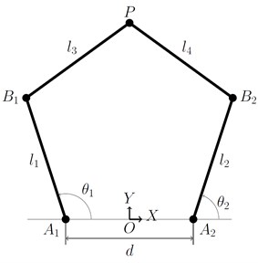
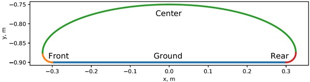
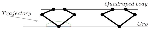
The end-effector point P has location coordinates , whose path traces the curve shown in Fig. 2. The path traced here comprises of four regions, the first region is the straight line along the floor, the second region is the quarter-circle at the end of the straight line, the third part comprises of semi-ellipse, and the last part includes a quarter circle which connects the semi-ellipse and the straight line. It should be noted that, the path shown in Fig. 2 is relative to the mechanism as the quadruped body moves forward. This is a simple path that we have assumed in the initial stage to solve the optimization problem for the 5R-PPM. Optimization of the path is not in the scope of this paper.
Fig. 2The trajectory of point P from 5R-PPM
2.2. Velocity kinematics
In kinematics analysis, the motion of the object is of interest without considering the forces acting on the body. In velocity kinematics, joint velocities and end-effector’s velocity are related by a matrix called Jacobian. The velocity kinematic analysis of the 5R-PPM is performed based on Fig. 1. The kinematic relationship among the coordinates is the starting point for deriving the equations for dynamic analysis of the 5R-PPM.
Consider Fig. 1, distance and are mentioned in terms of , , and are given in Eq. (1-2) as:
Differentiating Eq. (1) and Eq. (2), we obtain Eq. (3) as:
where, is , and is , and:
In Eq. (4), , , and respectively are the directed line segments between , , , and .
2.3. Inverse position kinematics
Inverse position kinematics starts with known end-effector position and computes the joint angles and so that the end-effector can reach the position.
Fig. 35R-PPM sketch for inverse kinematics
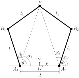
From Fig. 3, the following Eq. (5-6) can be derived:
where and are the lengths of the line segments and in Fig. 3, and are the angles made by these line segments and respectively with the horizontal, measured in the anti-clockwise direction given in Eq. (7-8) as:
The angle between and is , which is given in Eq. (9-10) as follows:
Similarly, the angle between and is , which is given in Eq. (11-12) as follows:
Thus, the relation between and can be written in terms of and , and is given in Eq. (13-14) as:
Based on the end-effector position within the reachable workspace, there are four possible solutions for the 5R-PPM. The four possible solutions are categorized based on the criteria that if link 1 and 3 or link 2 and 4 have an included angle measured from the proximal links less than or greater than . In Fig. 1, considering the odd-numbered links, link 1 and link 3, the included angle measures less than , and hence this is regarded as ‘’. In the same Fig. 1, considering the even-numbered links, link 2 and link 4, they make an angle which is greater than when measured in the counter-clockwise direction, and hence this is considered as ‘’.
Alternately, this can also be quickly verified by computing the cross product of and as well as the cross product of and . By incorporating the aforementioned convention, the four possible solutions are termed working modes, which are described as ‘’, ‘’, ‘’, and ‘’. To toggle between any two working modes, the mechanism has to cross Type-1 singularity. In a Type-1 singularity, the link becomes extended, i.e., (or) become collinear, but does not coincide with or . For each working mode, there are two assembly modes that partition the workspace of the working mode. In order to switch between two assembly modes, the mechanism needs to be disassembled at the end-effector joint. The assembly mode implies, for each active joint pair, there exist two distinct end-effector locations. To toggle from one to another assembly mode, the mechanism needs to traverse a Type-2 singularity. Distal links become collinear in a Type-2 singularity, i.e., from Fig. 1, are collinear.
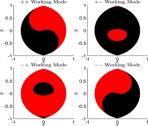
Fig. 4Working modes of 5R-PPM when all link lengths are equal
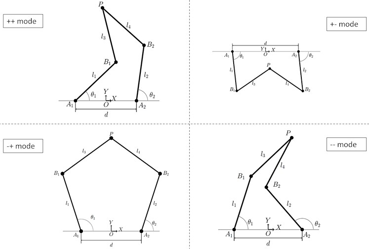
Initially, the 5R-PPM is considered to have all link lengths equal to as shown in Fig. 4. The workspaces for all the modes show that there are no holes in it as shown in Fig. 5. Loci of Type-1 singularity of 5R-PPM is given by arcs of a circle of radius centred at point and . In contrast, for all working modes, the combined loci of Type-2 singularity comprises of a sextic and two circles of radius when and coincide.
Fig. 5Workspace area of 5R-PPM when all link lengths are equal
The parametric equation for an arc of a circle [11] is given in Eq. (15-16) as:
where .
The parametric equation for sextic is given in Eq. (17-19) as:
The complete workspace is shown in Fig. 5. Initially, the mechanism can access the red colour region, with the black colour region becoming accessible when the assembly mode is changed. The parallel mechanism can swap its workspace by switching working modes as shown in Fig. 5.
2.4. Torque requirement
The relationship between the force acting at end-effector’s external surface and the joint torques acting at and is given in Eq. (20) as:
where and
Then, the Jacobian matrix is given in Eq. (21) as:
To obtain a unique solution for joint torques, both ‘’ matrix and ‘’ matrix should have full rank given the required force acting on the end-effector. We assume that the mechanism will not traverse through singularity during motion, thereby ensuring the full rank of Jacobian will exist.
For this study, certain additional assumptions were made as follows:
1) The path of the stance leg’s end-effector moves along a straight line, parallel to the quadruped body while maintaining a constant height during its forward motion.
2) The path of the swing legs’ end-effector will be a curve which is modelled to move the end-effector up from the floor as well as to move it to the following location on the floor. Moreover, the aim of lifting the foot off the floor is to negotiate any obstacles present on the floor and move over the obstacles.
3) The end-effector could be positioned anywhere in space at any desired location within the limits of the 5R-PPM workspace.
4) For trot gait, where two legs are in contact with the ground, the ground’s reaction force in the vertical direction is considered equivalent to one-half of the entire weight for motion with constant height.
The assumptions mentioned above should be satisfied at the least expense of actuator torque.
Let be friction coefficient between the foot and the ground surface. Then the maximum force in the horizontal direction is given as times the force in the vertical direction.
Let the Jacobian matrix be as follows as given in Eq. (22):
where, represents Jacobian matrix elements which depend on , , , and .
In Fig. 3, the configurations’ -axis is pointing upward. However, when the mechanism is mounted on the quadruped body, the force generated by the mechanism is downward, which is considered negative. , the force in the horizontal direction, could be positive or negative; it depends on whether the robot is accelerating or decelerating. Accordingly, Eq. (20) can be rewritten in Eq. (23-24) as:
As we are primarily interested in magnitude only, Eqs. (23-24) can be rewritten as shown in Eqs. (25-26) as:
From Eqs. (25-26), it can be inferred that the joint actuator torques are computed with the vertical force as the scaling factor. Thus, from Eq. (25-26), we can deduce that the coefficient of depends on kinematics alone, i.e., dependent on the end-effector trajectory alone.
2.5. Optimization
For minimum actuator torque, the mechanism dimensions optimized are link lengths and the distance of separation between the actuators at the base of the mechanism. The resulting mechanism need not have equal link lengths as the other 5R-PPMs studied in literature. Since the objective function is highly nonlinear, the search space will not be smooth. Genetic algorithm, which is well known for identifying global optimal solutions in high dimensional spaces, is chosen for searching through the dimension space to arrive at the optimal mechanism while satisfying the bounds on the dimensions.
From Eqs. (25-26), it can be seen that the vertical force is a scaling factor. As the weight of the robot increase, so does the vertical force applied on the mechanism. Hence, the weight of the quadruped robot body is taken as 1 N. The peak torque obtained from the solution of genetic algorithm is therefore per unit force applied by the body weight.
For the 5R-PPM considered here, the joint torque minimization problem could be framed as: “For the specified height of the quadruped and for the given path to be traced by the end-effector with respect to the mechanisms base, obtain the magnitudes , , , , and such that the joint actuator torques’ peak absolute values are minimum.”
The objective function or fitness function can be written as:
The bounds on the dimensions are taken as 0.2 m to 1 m length. A population size of 200 is taken for running the algorithm.
3. Results
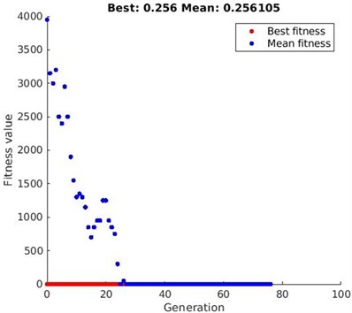
Using the genetic algorithm, the formulated minimization problem stated is solved and the convergence plot is shown in Fig. 6. After 76 generations the solutions converged, resulting in the minimum peak torque value of 0.256 N·m.
Fig. 6GA convergence path
As the range of 0.2 to 1 meter was given as bounds to the optimization algorithm, all the link lengths in the solution lie within this range. The quadruped robot was assumed to be one-newton weight, and accordingly, the actuator torque required to rotate the links is calculated in the optimization algorithm. The maximum actuator torque required for the mechanism to complete the path specified in Fig. 2 and link lengths of the mechanism obtained after optimization are listed in Table 1.
Table 1links length and torques for four working modes of mechanism
Working mode | L1 (meter) | L2 (meter) | L3 (meter) | L4 (meter) | (meter) | Torque (N·m) |
0.9771 | 0.5402 | 0.5382 | 0.6576 | 0.6271 | 0.3620 | |
0.9997 | 0.9654 | 0.5684 | 0.5336 | 0.5877 | 0.3650 | |
0.5532 | 0.4925 | 0.9198 | 0.8479 | 0.4474 | 0.2560 | |
0.5761 | 0.9905 | 0.6440 | 0.5486 | 0.7202 | 0.3640 |
Fig. 5 shows the workspace of the 5R-PPM for all four working modes plotted when all the mechanism links are of equal length, i.e., before optimizing the mechanism’s link lengths. In [23], it was stated that the ‘’ working mode yielded a good result, but there was no supporting evidence for the claim.
Fig. 7 shows the workspace area of the 5R-PPM after optimizing the mechanism in all the four working modes. It can be inferred from Fig. 7 and Table 1 that the ‘’ working mode gives the optimized values of the link lengths for lowest peak torque. The torque values of other working modes are more than 40 % higher when compared with the ‘’ working modes.
Initially, the mechanism is set-up to access the red colour region in the ‘’ working mode, which has a bigger workspace in that working mode. The other working mode shown as black region is quite small and requires, disassembly and reassembly to enter from the current assembly mode. The mechanism does not have any Type-1 or Type-2 singularity while moving along the assumed path (Fig. 2).
Fig. 7Workspace area of 5R-PPM after optimization
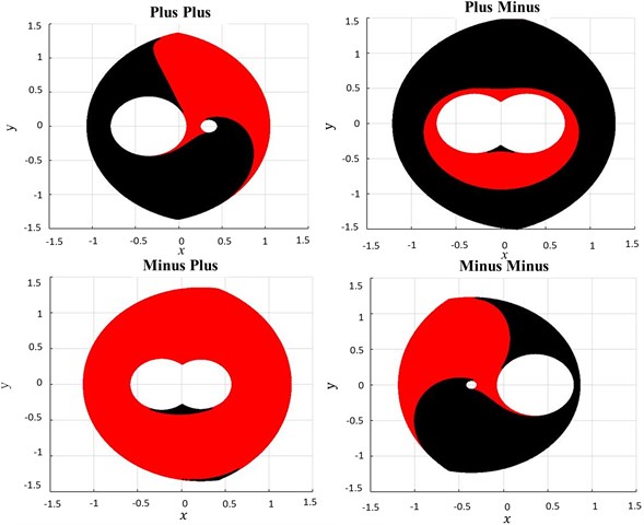
Fig. 85R-PPM simulation in MATLAB
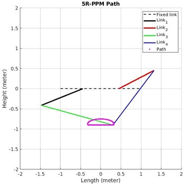
Fig. 8 shows the screenshot of Matlab simulation of 5R-PPM after optimizing the link lengths. The simulation can be viewed at ‘bit.ly/38GI3R3’. Fig. 9 shows the stick diagram of 5R-PPM simulation performed in Matlab Simscape Multibody. Results of the validation match the results found through genetic algorithm. The simulation of 5R-PPM performed in Matlab Simscape Multibody can be viewed at ‘bit.ly/3gKxsbS’.
Fig. 95R-PPM simulation in Simscape multibody
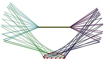
Fig. 10The torque required for optimized 5R-PPM
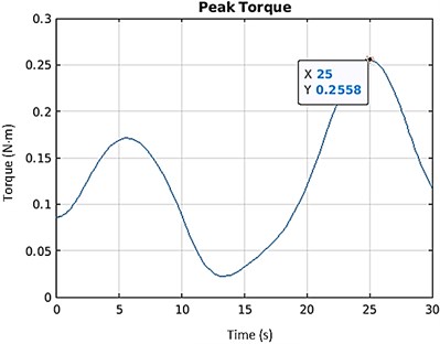
Fig. 11Planar sketch of quadruped with optimized 5R-PPM
The link lengths obtained from the optimization were used for modelling the links in Simscape Multibody. The path considered in Fig. 2 is provided as motion input to the Simscape Multibody. The torque computed as output by the toolbox is 0.2558 N·m (Fig. 10), which is close to the value obtained from genetic algorithm optimization. Thus, the optimized values are in agreement with the validated data, ascertaining the correctness of this study. Fig. 11 illustrates the intended application of 5R-PPM on quadruped. The mechanism will trace the path depicted in the Fig. 2.
4. Conclusions
Optimizing the actuator torque is essential for efficient design as actuators are expensive and heavier for higher torque. The results of this work give optimum link length values for a 5R-PPM. Kinematic analysis equations and dynamic analysis equations of the 5R-PPM were used to formulate the optimization problem. The genetic algorithm was used for optimization, and for the 5R-PPM, the values were obtained by evaluating all the four possible working modes. The mechanism with the optimized link lengths has the least amount of peak actuator torque for the assumed trajectory while having the maximum possible workspace. The ‘’ working mode gave the optimum result with the dimensions: the first link is 0.5532 m, the second link is 0.4925 m, the third link is 0.9198 m, the fourth link is 0.8479 m, and the distance between fixed points is 0.4474 m.
The optimization problem was programmed in MATLAB and validated in MATLAB Simscape Multibody. To facilitate visualization, the outcomes of this study were presented graphically. The prime objective of this work is to show that unsymmetric leg lengths in 5R-PPMs can give better results than symmetric leg lengths. The numerical results arrived at through optimization in this work need to be further evaluated through experiments.
References
-
L. Campos, F. Bourbonnais, I. A. Bonev, and P. Bigras, “Development of a five-bar parallel robot with large workspace,” in ASME 2010 International Design Engineering Technical Conferences and Computers and Information in Engineering Conference, pp. 917–922, Jan. 2010, https://doi.org/10.1115/detc2010-28962
-
S. Briot and I. A. Bonev, “Are parallel robots more accurate than serial robots?,” Transactions of the Canadian Society for Mechanical Engineering, Vol. 31, No. 4, pp. 445–455, Dec. 2007, https://doi.org/10.1139/tcsme-2007-0032
-
G. Alıcı, “Determination of singularity contours for five-bar planar parallel manipulators,” Robotica, Vol. 18, No. 5, pp. 569–575, Sep. 2000, https://doi.org/10.1017/s0263574700002733
-
D. Zhaocai, Y. Yueqing, and Z. Xuping, “Dynamic modeling of flexible-links planar parallel robots,” Frontiers of Mechanical Engineering in China, Vol. 3, No. 2, pp. 232–237, Jun. 2008, https://doi.org/10.1007/s11465-008-0032-3
-
M. Z. Huang, “Design of a planar parallel robot for optimal workspace and dexterity,” International Journal of Advanced Robotic Systems, Vol. 8, No. 4, p. 49, Sep. 2011, https://doi.org/10.5772/45693
-
F. Gao, C. Qi, Q. Sun, X. Chen, and X. Tian, “A quadruped robot with parallel mechanism legs,” in 2014 IEEE International Conference on Robotics and Automation (ICRA), pp. 2566–2566, May 2014, https://doi.org/10.1109/icra.2014.6907223
-
G. Cui and Y. Zhang, “Kinetostatic Modeling and Analysis of a New 3-DOF Parallel Manipulator,” in 2009 International Conference on Computational Intelligence and Software Engineering, pp. 1–4, Dec. 2009, https://doi.org/10.1109/cise.2009.5364146
-
X.-J. Liu, J. Wang, and G. Pritschow, “Performance atlases and optimum design of planar 5R symmetrical parallel mechanisms,” Mechanism and Machine Theory, Vol. 41, No. 2, pp. 119–144, Feb. 2006, https://doi.org/10.1016/j.mechmachtheory.2005.05.003
-
E. Macho, O. Altuzarra, C. Pinto, and A. Hernandez, “Workspaces associated to assembly modes of the 5R planar parallel manipulator,” Robotica, Vol. 26, No. 3, pp. 395–403, May 2008, https://doi.org/10.1017/s0263574707004109
-
J. Hesselbach, M. B. Helm, and S. Soetebier, “Connecting Assembly Modes for Workspace Enlargement,” in Advances in Robot Kinematics, Dordrecht: Springer Netherlands, 2002, pp. 347–356, https://doi.org/10.1007/978-94-017-0657-5_37
-
A. Figielski, I. A. Bonev, and P. Bigras, “Towards development of a 2-DOF planar oparallel robot with optimal workspace use,” in 2007 IEEE International Conference on Systems, Man and Cybernetics, pp. 1562–1566, Oct. 2007, https://doi.org/10.1109/icsmc.2007.4413840
-
A. K. Dash, I.-M. Chen, S. H. Yeo, and G. Yang, “Workspace generation and planning singularity-free path for parallel manipulators,” Mechanism and Machine Theory, Vol. 40, No. 7, pp. 776–805, Jul. 2005, https://doi.org/10.1016/j.mechmachtheory.2005.01.001
-
S. Kock and W. Schumacher, “A parallel x-y manipulator with actuation redundancy for high-speed and active-stiffness applications,” in IEEE International Conference on Robotics and Automation, pp. 2295–2300, 1998, https://doi.org/10.1109/robot.1998.680665
-
D. Basu and A. Ghosal, “Singularity analysis of platform-type multi-loop spatial mechanisms,” Mechanism and Machine Theory, Vol. 32, No. 3, pp. 375–389, Apr. 1997, https://doi.org/10.1016/s0094-114x(96)00033-x
-
G. L. Long and R. P. Paul, “Singularity avoidance and the control of an eight-revolute-joint manipulator,” The International Journal of Robotics Research, Vol. 11, No. 6, pp. 503–515, Dec. 1992, https://doi.org/10.1177/027836499201100601
-
Z. C. Lai and D. C. H. Yang, “A new method for the singularity analysis of simple six-link manipulators,” The International Journal of Robotics Research, Vol. 5, No. 2, pp. 66–74, Jun. 1986, https://doi.org/10.1177/027836498600500207
-
C. Gosselin and J. Angeles, “Singularity analysis of closed-loop kinematic chains,” IEEE Transactions on Robotics and Automation, Vol. 6, No. 3, pp. 281–290, Jun. 1990, https://doi.org/10.1109/70.56660
-
H. R. Mohammadi Daniali, P. J. Zsombor-Murray, and J. Angeles, “Singularity analysis of planar parallel manipulators,” Mechanism and Machine Theory, Vol. 30, No. 5, pp. 665–678, Jul. 1995, https://doi.org/10.1016/0094-114x(94)00071-r
-
C. L. Collins and G. L. Long, “The singularity analysis of an in-parallel hand controller for force-reflected teleoperation,” IEEE Transactions on Robotics and Automation, Vol. 11, No. 5, pp. 661–669, 1995, https://doi.org/10.1109/70.466600
-
F. Bourbonnais, P. Bigras, and I. A. Bonev, “Minimum-time trajectory planning and control of a pick-and-place five-bar parallel robot,” IEEE/ASME Transactions on Mechatronics, Vol. 20, No. 2, pp. 740–749, Apr. 2015, https://doi.org/10.1109/tmech.2014.2318999
-
S.-L. Wang and K. J. Waldron, “A Study of the singular configurations of serial manipulators,” Journal of Mechanisms, Transmissions, and Automation in Design, Vol. 109, No. 1, pp. 14–20, Mar. 1987, https://doi.org/10.1115/1.3258779
-
S. Sen, B. Dasgupta, and A. K. Mallik, “Variational approach for singularity-free path-planning of parallel manipulators,” Mechanism and Machine Theory, Vol. 38, No. 11, pp. 1165–1183, Nov. 2003, https://doi.org/10.1016/s0094-114x(03)00065-x
-
Mangesh D. Ratolikar, R., and Prasanth Kumar, “Optimal 5R parallel leg design for quadruped robot gait cycle,” Vibroengineering PROCEDIA, Vol. 35, pp. 94–98, Nov. 2020, https://doi.org/10.21595/vp.2020.21806
About this article

