Abstract
Based on the structural features of a rigid rotor on squirrel cages elastic supports, a finite element (FE) model of the system including squirrel cages is adopted to study its vibration and stress characteristics under the case of bearing misalignment. Firstly, the equations of motion are derived through Lagrange method to obtain the basic dynamic characteristics. Then a three dimensional FE model is established and validated after model updating on basis of the calculated and measured modes and imbalance response. Finally, the influences of bearing misalignment on the rigid rotor system on elastic supports are studied. Results reveal that, for the rigid rotor on elastic squirrel cages supports, bearing misalignment has no obvious influence on the transverse vibration of shaft. However, the stress level on squirrel cage increases significantly, which means the easier damage of bearing and squirrel cage when the bearing misalignment appears.
1. Introduction
Elastic supports such as squirrel cage and squeeze film damper are widely used in rotor systems, in order to adjust the critical speed and reduce the vibration level of the whole engine [1]. The existence of elastic supports produces two modes with deformation occurs mainly on elastic supports, and increases the frequency of shaft bending [2]. When the rotor operates near the first two modes, it can be considered as rigid rotor on elastic supports [3].
In the dynamics of rigid rotor on elastic supports, some researchers have made many contributions. Kel’zon [4] and Pasynkova [5] found that when the rotational frequency increases without limit, a rigid rotor on elastic bearings possesses a self-centring property similar to that of a flexible Lava1 shaft. Adiletta [6] studied the dynamic behaviour of a rigid rotor supported on plain journal bearings. Describing the equations of motion by five Lagrangian co-ordinates and three angular co-ordinates, he investigated the cylindrical whirl and a conical whirl of the rotor system. Moreover, he also performed an experimental confirmation of the theoretical results [7]. Arkhipova [8] analyzed the possible types of steady motions of a rigid unbalanced rotor in nonlinear elastic bearings and obtained the conditions for the onset of self-excited vibrations.
The problem of misalignment in rotor systems is of great concern to designers and engineers, for it may cause a series of harmful effects including the violent vibration of shafts, bearing wear, and even rubbing between rotor and stator.
Redmond [9] presented a model which can account for both angular and parallel misalignments in the presence of mass unbalance. Al-Hussain [10] examined the effect of angular misalignment on the stability of two rotors connected by a flexible mechanical coupling. Their results show that an increase in angular misalignment can lead to an increase of the model stability region. In addition, the angular and parallel misalignments are distinct. Gao [11] developed an analytical vibration model for simulation, and analyzed the effect of nonconcentricity of bearing housings by applying loads and moments acting on the bearings, His results show that the natural frequencies, unbalance responses of the rotor system vary with the increase of misalignment between two bearing housings. Feng [12] studied the bearing misalignment of an inner-and-outer dual-rotor system in an aero-engine and analyzed the vibration responses of the rotor system under different misalignments and rotational speeds.
However, the above researches all adopt the simple rotor model, which are difficult to simulate the practical rotor vibration in some cases, especially for the rotor systems with complex elastic supported structures. Moreover, researches on the misalignment in rigid rotor system on elastic supports are very limited.
In this paper, a three-dimensional finite element model of a rotor test rig with squirrel cages is established to investigate the influence of bearing misalignment on the vibration characteristics of rigid rotor systems with elastic supports. Firstly, the equations of motion are derived through Lagrange method to obtain the basic dynamic characteristics. For the three-dimensional finite element model, model updating and validation is conducted on basis of the calculated and measured modes and imbalance response. Results reveal that, for rigid rotor on elastic squirrel cages supports, bearing misalignment has no obvious influence on the transverse vibration of shaft, while the stress level on squirrel cage increases significantly.
2. Governing equations of rigid rotor system on elastic supports
2.1. Description of the rotor system
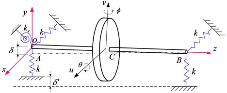
A rotor test rig is designed to study the vibrations of the misalignment rotor system, as shown in Fig. 1. It consists of a hollow shaft and two bearings on squirrel cages. A steel disk is installed on the middle of shaft. Parameters of the rotor system are listed in Table 1.
Fig. 1The rigid rotor rig on two supports of squirrel cages
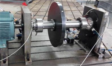
a) Photo of the rotor test rig
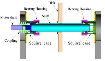
b) Sketch of the rotor test rig
Table 1Parameters of rotor system
Parameters | Values |
Shaft length | 498 mm |
External diameter of shaft | 70 mm |
Inner diameter of shaft | 56 mm |
External diameter of disk | 410 mm |
Inner diameter of disk | 79 mm |
Disk thickness | 30 mm |
Distance of the disk to nearby bearing center | 200 mm |
Distance of the bearing center to nearby shaft end | 49 mm |
Young’s modulus | 2.09×10¹¹Pa |
Mass density | 7870 kg/m3 |
Poisson's ratio | 0.3 |
2.2. The equations of motion
Schematic of a rotor system in test rig is shown in Fig. 2, which is considered as a rigid rotor on elastic supports with isotropic stiffness . The mass center is located at distances and from the bearings. The polar moment of inertia is defined as and the transversal moment of inertia is defined as .
Fig. 2Schematic of the rotor system
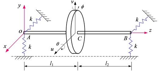
The kinematics is described by 4 coordinates, which are, transverse displacements of the mass center along and direction: and , rotations about the and : and . With these 4 coordinates, the displacements at the supports can be expressed as:
The strain energy of the elastic supports is:
Substituting Eq. (1) into Eq. (2) obtains:
For the rotor test rig shown in Fig. 1, and the last term in Eq. (3) disappears.
The kinematic energy of the rotor system is the sum of the translational and the rotational kinetic energy. The total kinetic energy is:
The four Lagrange equations are:
Introducing the complex coordinates:
Then Eq. (5) can be written as:
where .
The former equation of Eq. (7a) represents the cylindrical mode and the latter represents the concial mode. By solving the characteristic Eq. (8), frequency of the conical mode can be obtained:
The solutions consists of a Forward Whirl at :
and the Backward Whirl :
Eq. (9) reveals that, the forward whirl frequency of the conical mode when , which indicates the inexistence of forward whirl critical speed.
For the test rig shown in Fig. 1, parameters for simulations are listed in Table 2.
Table 2Parameters of rotor system in simulations
Parameter | Value |
Distance of the mass center to bearing | 0.215 m |
Mass | 43 kg |
Polar moment of inertia | 0.7523 kg∙m2 |
Transversal moment of inertia | 0.6015 kg∙m2 |
Stiffness | 4.84e6 N/m |
3. Three-dimensional finite element modeling of the rotor system
To account for systems with complex rotor geometry or attached nonsymmetric components such as bladed disks, modeling using 3D solid elements is commonly needed, with the advantage of accurate gyroscopic effect and nonlinear effects [13-16]. The existing literature shows that, although the models are complex and fine, supporting structures are always simply modelled as spring or bearing elements. However, for the rigid rotor system shown in Fig. 1, squirrel cages should be accurately modelled because strain energy is mainly distributed on the cages.
3.1. Modeling of the component
Bolt hole, chamfer and other tiny structures are overlooked and the main components are modelled, as shown in Table 3 and Fig. 3.
Table 3Modelling of the main components
Component | Modeling | Element | Element number |
Mounting Seat | Coarse solid | solid45 | 785 |
Connection Pad | Coarse solid | solid 45 | 2465 |
Squirrel cage | Fine solid | solid 186 | 773 |
Bearing housing | Coarse solid | solid 45 | 863 |
Bearing | Simplification | combin14 and mass21 | 4 |
Shaft and disk | Coarse solid | solid45 | 979 |
3.2. Connecting relations and boundary conditions
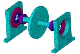
Mounting seat, connection pad, squirrel cage and bearing housing are rigid-connected together. A master node is established at the center of the hollow shaft and coupled with the corresponding nodes on shaft as rigid region. Bearing is simplified as four Combin14 elements with stiffness of 1×10⁸ N/m. All DOFs of nodes at the bottom of mounting seat are constrained. Finite element model of the rotor system is shown in Fig. 4, which has 10070 elements and 24812 nodes in all.
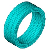
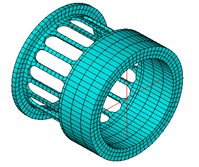
Fig. 3Finite element model of some components
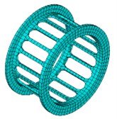
a) Squirrel cage
b) Bearing
c) Bearing Housing
d) Assembly
Fig. 4Finite element model of the rotor system
4. Model updating and validation by natural characteristics and imbalance response
4.1. Natural frequencies and modal shapes
Frequencies and modal shapes of the first three orders obtained by 3D finite element model are shown in Fig. 5. The results reveal that, for the 1st and 2nd mode, deformations mainly occur on the squirrel cages. Difference value between the 2nd and the 3rd order frequencies is over 500 Hz. When the running speed is below the 3rd mode, the rotor system can be considered as a rigid rotor on elastic supports.
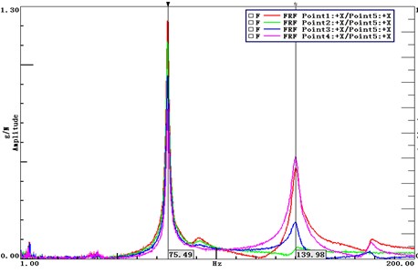
Hammering method is used to obtain the natural frequencies of the static system and the FRF curves are shown in Fig. 6. Two peaks appear in the FRF, whose frequencies are 75.49 Hz and 139.98 Hz, respectively.
Fig. 5The first three modes of the rotor system
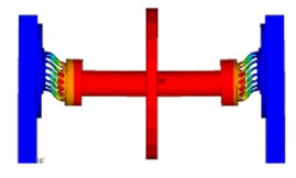
a) 75.85 Hz
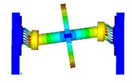
b) 125.44 Hz
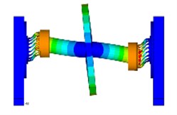
c) 648.33 Hz
Table 4Frequencies obtained by simulation and modal test
Order | Simulation / Hz | Experiment / Hz | Error / % | |
Initial results | 1 | 75.85 | 75.49 | 0.48 |
2 | 125.44 | 139.98 | 10.39 | |
Results after model updating | 1 | 75.05 | 75.49 | 0.58 |
2 | 138.25 | 139.98 | 1.24 |
The difference ratio of the 2nd order frequency between calculated and experimental results is relatively large, which results from the inconsistent of mass and moment of inertia because of the overlook of the bearing mass in modeling process. Model updating is adopted based on the measured modes and the results are listed in Table 4.
Fig. 6FRF curves obtained by hammering method
4.2. Critical speed
Campbell diagram of the rotor system when the rotational frequency varies from 0 to 300 Hz, as shown in Fig. 7. Campbell diagram reveals that natural frequency of the 1st order is not affected by rotational speed, while the 2nd order shows obvious difference between the forward and backward whirling motions. Critical speed of the first two orders are listed in Table 5.
Fig. 7Campbell diagram of the rotor system
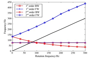
a) FE results
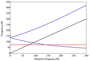
b) Analytical results
Table 5Critical speeds of the rotor system
Order | The 1st order | The 2nd backward whirl |
FE method | 75.97 Hz | 83.75 Hz |
Analytical method | 75.51 Hz | 91.8 Hz |
Test | 74.63 Hz | – |
The rotor starts up from 0 Hz up to 90 Hz rapidly and then freely decays to stationary state. Electrical vortex sensor is used to detect the vibration of the supporting point. Spectrum cascade obtained in run-up and free decay test is shown in Fig. 8. Peak of the vibration amplitude appears at 74.63 Hz, which corresponds to the 1st order critical speed.
4.3. Imbalance response
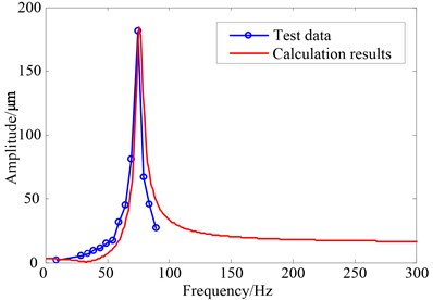
Damping parameters should be determined when the imbalance response is calculated. Using of the amplitude-frequency diagram and Half-power Bandwidth Method:
Damping ratio is obtained as 0.0356.
The amount of unbalance 50 g∙cm, combined with the damping ratio 0.0356 are introduced into the finite element model. Transverse responses of the node near the end far from motor are shown in Fig. 9, in which the simulated and measured results agree well with each other.
Results of the natural characteristics, critical speed and imbalance response all validate the effectiveness of the 3D finite element model.
Fig. 8Spectrogram obtained by run-up and free decay test
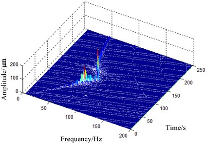
Fig. 9Comparision of the simulated and measured results
5. Analysis of the misalignment rigid rotor on two elastic supports
5.1. Description of the bearing misalignment
For the rotor system with two bearings as shown in Fig. 1, bearing misalignment often appears on the bearing far from the motor end (see Fig. 10). When the mounting seat has a bias of and thus bearing has an eccentricity of , the deformation mainly appears on the squirrel cage elastic supports and an additional bending moment arises.
In the FEM of rotor system, a bias is imposed the mounting seat to simulate the bearing misalignment. Response of the gyroscopic effect and large rotation effects is considered in the calculation. Then vibrations of the shaft and the stress on squirrel cage elastic supports are investigated.
Fig. 10Rigid rotor on elastic supports with bearing misalignment
5.2. Vibration of the shaft
Three cases are selected for simulation, that is below the 1st order critical speed 65 Hz, at the critical speed 75 Hz and over the 1st order critical speed 85 Hz. Simulation results are shown in Table 6 and Fig. 11.
Fig. 11 shows the transverse vibrations and rotor orbits at different rotational speeds under the eccentricity 2 mm. No obvious features appear in the frequency spectra and orbits. Measured results show the same feature, as shown in Fig. 12.
Fig. 11Simulation results when eccentricity δ'= 2 mm
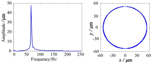
a)65 Hz
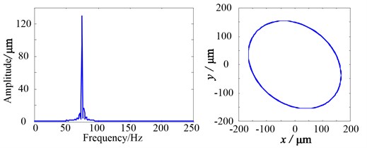
b)75 Hz
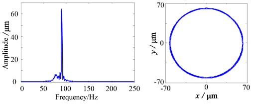
c)85 Hz
Fig. 12Measured results when δ'= 2 mm at the frequency of 65 Hz
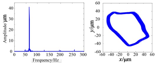
Table 6Transverse vibration of the shaft / μm
1 mm | 2 mm | ||
65 Hz | 53.81 | 53.59 | 47.86 |
75 Hz | 137.20 | 137.21 | 138.18 |
85 Hz | 62.21 | 62.22 | 62.22 |
Table 7Comparison of the simulation and experiment at Ω= 65 Hz
/ mm | 0 | 1 | 2 |
Simulation / µm | 53.81 | 53.59 | 47.86 |
Experiment / µm | 44.84 | 46.65 | 41.03 |
5.3. Stress on the squirrel cage elastic supports
Stress is calculated and measured to study the influence of the bearing misalignment on the dynamic stresses of squirrel cage elastic supports. The location of strain gauge is shown on Fig. 13.
Fig. 13Location of the strain gauge
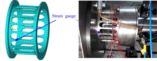
Fig. 14Stress of simulation on the squirrel cage elastic supports
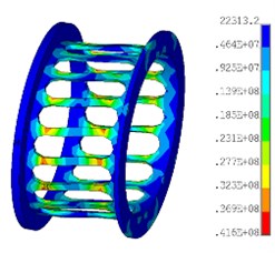
a) Distribution of the stress
b)
c)1 mm
d)2 mm
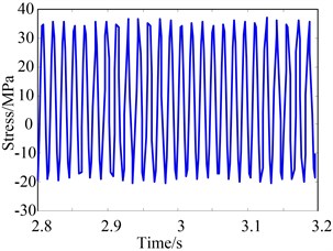
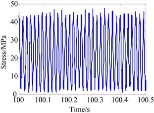
Fig. 14(a) shows the stress distribution on squirrel cage elastic supports, and Fig. 14(b)-14(d) illustrate the stress under different eccentricities, which are obtained by simulation. It can be seen that, the stress values increase with the increase of eccentricity . However, the peak-to-peak value is consistent.
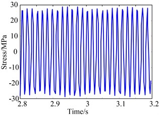
Fig. 15 is the measured results of stress on the squirrel cage, the same features as simulation is obtained.
Fig. 15Stress of the measured results at 65 Hz when δ'= 2 mm
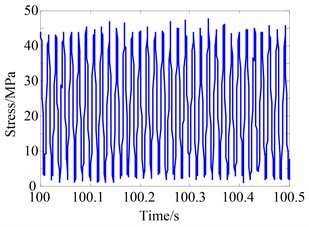
a) Time domain wave
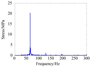
b) Frequency spectrum
6. Conclusions
In this paper, a three-dimensional finite element model of a rotor system in a test rig is established to investigate the influence of bearing misalignment on vibration responses of a rigid rotor system with elastic supports.
Firstly, the equations of motion are derived through Lagrange method to obtain the basic dynamic characteristics. Then a three-dimensional finite element model is established after model updating and validation on basis of the calculated and measured modes and imbalance response.
The simulated and experimental results all reveal that, for rigid rotor on elastic squirrel cages supports, bearing misalignment has no obvious influence on the transverse vibration of shaft, while the stress level on squirrel cage increases significantly.
References
-
Chen G. A new rotor-ball bearing-stator coupling dynamics model for whole aero-engine vibration. Journal of Vibration and Acoustics, Vol. 131, Issue 6, 2009, p. 061009.
-
Yan L. Vibration and Vibration Reduction of Aero Gas Turbine. National Defence Industry Press, Beijing, 1991, (in Chinese).
-
Han Q., Yu T., Li H., et al. Hybrid model based identification of local rubbing fault in rotor systems. Key Engineering Materials, Vol. 293, 2005, p. 355-364.
-
Kel’zon A. S. Self-centering and balancing of a rigid rotor rotating in two elastic bearings. Doklady Akademii Nauk SSSR, Vol. 110, Issue 1, 1956, p. 31-33.
-
Pasynkova I. A. The stability of conical precession of a rigid unbalanced rotor. Matematika Mekhanika Astronomiya, Vestnik, Sankt-Peterburgskogo Universiteta, Vol. 1, 1998, p. 82-86.
-
Adiletta G., Guido A. R., Rossi C. Nonlinear dynamics of a rigid unbalanced rotor in journal bearings. Part 1: Theoretical analysis. Nonlinear Dynamics, Vol. 14, 1997, p. 57-87.
-
Adiletta G., Guido A. R., Rossi C. Nonlinear dynamics of a rigid unbalanced rotor in journal bearings. Part 2: Experimental analysis. Nonlinear Dynamics, Vol. 14, 1997, p. 157-189.
-
Arkhipova I. M. Dynamics of a rigid rotor in the elastic bearings. Theoretical and Applied Mechanics, Vol. 31, Issue 1, 2004, p. 73-83.
-
Redmond I. Study of a misaligned flexibly coupled shaft system having nonlinear bearings and cyclic coupling stiffness – theoretical model and analysis. Journal of Sound and Vibration, Vol. 329, Issue 6, 2010, p. 700-720.
-
Al-Hussain K. M. Dynamic stability of two rigid rotors connected by a flexible coupling with angular misalignment. Journal of Sound and Vibration, Vol. 266, 2003, p. 217-234.
-
Yuan G., Zhengmei L., Fangbo M., et al. Influences of bearing housing nonconcentricity on vibration characteristics of rolling element bearing-rotor system. Proceedings of the Institution of Mechanical Engineers, Part K: Journal of Multi-body Dynamics, Vol. 228, Issue 4, 2014, p. 388-399.
-
Feng G., Zhou B., Lin L., et al. Misalignment analysis for support bearing in an inner-and-outer dual rotor system. Journal of Vibration and Shock, Vol. 31, 2012, p. 142-147.
-
Chaudhry J. A. 3-D Finite Element Analysis of Rotors in Gas Turbines, Steam Turbines and Axial Pumps Including Blade Vibrations. University of Viginia, Virginia, 2011.
-
Wagner M. B., Younan A., Allaire P., et al. Model reduction methods for rotor dynamic analysis: a survey and review. International Journal of Rotating Machinery, Vol. 2011, 2010, p. 273716.
-
Ma W., Wang J. 3D solid finite element modeling and rotordynamics of large rotating machines: application to an industrial turbo engine. Advanced Materials Research, Vol. 591, 2012, p. 1879-1885.
-
Sinha S., Dorbala S. Dynamic loads in the fan containment structure of a turbofan engine. Journal of Aerospace Engineering, Vol. 22, Issue 3, 2009, p. 260-269.
Cited by
About this article

This work is financially supported by Natural Science Foundations of China (Nos. 51175070, 51505060, 11472068).
Qingkai Han proposed the general idea and completed the writing of this paper. He also provided guidance of the calculation and experiment for the misalignment rigid rotor systems. Yugang Chen conducted the calculation for vibrations of rigid rotor systems with misalignment on squirrel cage supports and designed the test rig. Hao Zhang performed the experiment and data processing for critical speed, imbalance response and vibration of the misalignment rotor system. Lingli Jiang conducted the modal test for rotor system of the test rig in model updating. Xuejun Li made many significant suggestions for the revise of this paper before and during the submission of this paper.
