Abstract
Short seal (e.g. shroud seal) is a key component for the safe and reliable operation of a turbine unit. This paper sets up the three dimensional numerical model of a short labyrinth seal and analyzes its characteristics of the fluid-induced force. Results show that the tangential fluid-induced force increases almost linearly as the rotational speed increases. The sign of the radial fluid-induced force changes as the rotational speed increases. For higher inlet pressure, a more dramatic increase can be found for both the tangential and radial fluid-induced force. A transition speed range was found that the magnitude of the radial fluid-induced force at higher inlet pressure became less than that at lower inlet pressure. For each seal cavity, the peak pressure location had a shift away from the minimum clearance location as the rotational speed increased. This shift also existed in the axial direction. The effect of the rotational speed on the fluid-induced force became more remarkable for the longer seal with many cavities. Both the radial and tangential fluid-induced force increased with the increasing preswirl ratio. However, the two forces decreased with the increasing preswirl ratio when the inlet total pressure was kept as a constant value. In the end, the critical preswirl ratio which corresponds to zero tangential fluid-induced force was calculated, and results show that a smaller magnitude of the preswirl ratio will be needed to offset the effect of rotational speeds at higher inlet pressures. The inlet preswirl generated a majority of the tangential force for short seals.
1. Introduction
Labyrinth seal in turbomachineries is the key component that is employed to minimize the fluid leakage and improve the unit efficiency. With the improvement of turbine operating parameters, the system instability problem due to labyrinth seals, which is usually called fluid-induced vibration, becomes more and more serious. Inlet preswirl and rotor rotation are the two main sources of fluid-induced force [1]. A lot of research on shaft end seals has been carried out to investigate the influence of the two factors on the rotor characteristics in the past several years. Compared with shaft end seals, there are generally fewer teeth for short seals (e.g. shroud seals). Due to the special working condition, the mechanism of fluid-induced force generation as well as the relationship between inlet preswirl and rotor rotation speed need further investigation.
Reducing the circumferential fluid flow in seal cavities is the main goal to lower cross stiffness coefficients and increase direct damping coefficients. In addition to the generated fluid-induced force for the shroud turbine, mixing due to the difference in tangential velocity between the main stream flow and the leakage flow creates a significant proportion of the total loss associated with shroud leakage flow [2]. To reduce the circumferential fluid flow entering seals, arrangements of anti-swirl devices and swirl brakes have been two main approaches over the past decades.
Muszynska [3] presented the anti-swirl concept, which was based on the injection of an additional flow to the seal in the tangential direction opposite to the direction of the shaft rotation. Kim [4] presented a new anti-swirl self-injection mechanism achieved by deliberately machining self-injection holes inside the seal stator to partially divert inlet flow into the anti-swirl direction. Test results showed that the self-injection mechanism significantly improved whirl frequency ratios; however, the leakage performance degraded due to the introduction of the self-injection mechanism. Soto [5] firstly measured rotordynamic data for labyrinth seals with shunt injection. A comparison was made between conventional labyrinth seals, labyrinth seals with shunt injection (radial and against rotation), and a honeycomb seal. Results showed that labyrinth seals with injection against rotation were better able to control rotordynamic instabilities than labyrinth seals with radial injection; however, the leakage was slightly higher. The effectiveness of the shunt-injection against rotation in developing effective damping was reduced with increasing rotor surface velocity. Kim [6] proposed a CFD perturbation model for turbomachinery seal rotordynamics for labyrinth shunt injection with an arbitrarily high pressure gas. The drastically reduced (negative) cross-coupled stiffness, which was the primary advantage from the use of shunt injection in gas labyrinth seal applications, was well predicted. It was found that moving the injection toward the high pressure end of the seal gave cross-coupled stiffness coefficient, direct damping coefficient and effective damping coefficient values that were only slightly more stabilizing. Lv [7] investigated the influence of water pumping, water injection and gas injection to fluid-induced vibration in the seal clearance caused by rotor eccentricity. The fluid-induced vibration in the seal clearance can be suppressed when the air was injected at the upstream position of the minimum clearance. The best vibration attenuation effect was got when the air is injected at the position of 40°, and approximately 28 % vibration attenuation was obtained. It will have a negative effect if the air was injected at any downstream position. The rotor vibration amplitude changed with the flow rate value of air injection.
Kwanka [8] investigated the influence of swirl brakes on the labyrinth seal with smooth or honeycomb stators. Results showed that the use of swirl brakes at the entrance of the seal was highly effective. The swirl brakes reduced the preswirl and, as a consequence the cross-coupled stiffness, and they even increased the direct damping. Kwanka [9] proposed a new, easy-to-handle identification procedure using the stability behavior of a flexible rotor to determine the dynamic coefficients. It was found that swirl brakes were perfectly well suited for a subsequent installation in turbomachines with stability problems. Guinzburg [10] investigates the contributions to the rotordynamic forces from the discharge-to-suction leakage flows between the front shroud of the rotating impeller and the stationary pump casing. The effect of swirl was to increase the tangential force, thereby also increasing the range of whirl ratios for which there was a potentially destabilizing force. Thus reducing the swirl to the flow would be stabilizing. As for the normal force, swirl seemed to decrease the force at higher positive whirl ratios. The effects of swirl were in contrast to the effects of increasing the leakage flow, which cause a decrease in the normal force and an increase in the tangential force. Robic [11] investigated the effect of three inlet preswirl condition, –45, 0, +45 degrees on the flow characteristics of plain annular and labyrinth seals. It was found that inlet swirl put high pressure toward the maximum clearance area. Preswirl is found to have a destabilizing effect in general. Nielsen [12] presented the experimental and the theoretical data for two interchangeable swirl brakes designed in connection with the Space Shuttle Main Engine (SSME) Alternate Turbopump Development (ATD) High-Pressure Fuel Turbopump (HPFTP) program. Comparison of the swirl brake performance revealed that a nonaerodynamic swirl brake design proved to be better than an aerodynamic design. The flow was seen to be strongly three-dimensional from identifying the vortex flow structures within the vanes responsible for swirl brake performance. Brown [13] presented the test results for the rotordynamic coefficients of a hole-pattern annular gas seal with negative preswirl. Results showed that changes in the pressure ratio had only small effects on most rotordynamic coefficients, while increasing rotor speed significantly increased the cross-coupled stiffness and cross-coupled damping. Childs [14] presented test results for a 16-tooth labyrinth seal with positive inlet preswirl (in the direction of shaft rotation) for the following inlet conditions: (1) No swirl brakes, (2) Straight, conventional swirl brakes, and (3) Negative-swirl swirl brakes. The effective damping was large and positive for the negative-swirl configuration and near zero for the no-brake and conventional-brake designs.
Though employing proper preswirl can reduce fluid-induced force of labyrinth seals, especially for short labyrinth seals, and improve the system efficiency and stability, it is related with many factors, such as pressure ratio, flow rate, rotational speed, etc. It would be interesting to examine the relationships among them. However, this would be complicated and time consuming through experimental research due to the limited inlet preswirl, rotational speed, variable pressure ratios, etc. This paper analyzes the characteristics of the fluid-induced force for the short labyrinth seal by CFD method. The CFD model demonstrates a good agreement with the published experimental results. The influence of rotational speeds, pressure ratio and inlet preswirl are examined in eccentric conditions. The relationships among these factors are analyzed.
2. Numerical model
In this paper, the numerical model of short labyrinth seals is based on Rajakumar’s experimental facility [15]. The labyrinth seal contains four teeth totally. The seal teeth are on the rotor. Seal tests were conducted at five different eccentricity ratios (0, 0.15, 0.31, 0.43, 0.57) for two different inlet pressures of 1.093 atm and 1.069 atm. At each pressure and eccentricity combination three rotor rotational speeds were investigated setting 0 rpm, 1250 rpm and 2025 rpm. The swirl velocity introduced by the 45-degree-holes swirl plate was measured using a pitot tube introduced through a drilled hole in the stator at the seal inlet plane.
Fig. 1Two-dimensional structure diagram of the seal geometry
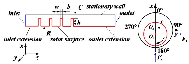
An advantage of using CFD is its capacity to analyze a large number of complex design configurations and parameters, and the use of CFD analysis in many rotary machines has been increasing rapidly in recent years with the development of commercial software [16-21]. In this paper, the Reynolds-Averaged-Navier-Stokes (RANS) CFD analysis of the whole flow field is performed by the ANSYS FLUENT 15.0 software. FLUENT is a finite-volume-based code, and it solves the equations for conservation of mass, momentum, and energy in terms of the dependent variables, velocity and pressure. Three-dimensional computational grids for the seal are generated using the Gambit 2.4.6 software. A complete asymmetric 360 degrees model is established, and the model takes the effect of rotor eccentricity into account. Fig. 1 shows the two-dimensional structure diagram of the seal geometry. The eccentric direction of the rotor is along the negative direction of the -axis. Zero degree is defined at the location with maximum clearance. The details of the seal geometry are shown in Table 1.
Due to the limitation of laboratory conditions, many operational conditions cannot be realized, such as high rotational speed, pressure ratio, inlet preswirl, etc. However, these limitations can be overcome through CFD method. Table 2 shows the boundary conditions defined for the seal. An adiabatic boundary condition is imposed for the stationary wall and the rotating surface, and all walls in the model have a no slip boundary condition. The calculation assumes the fluid to be an ideal gas at constant temperature and the entire flow to be turbulent. The RNG - model is used for the turbulent compressible flow. The momentum equations, the continuity equation, and the turbulence model equations are solved using the SIMPLE pressure-velocity coupling algorithm. Second-order upwind discretization is employed for momentum and energy equations, and the pressure is discretized with second-order scheme. The fluid-induced force can be obtained by integrating the uneven pressure acting on the rotor surface.
Table 1Seal dimensions
Tooth number | Tooth height / mm | Cavity width / mm | Tooth width / mm | Seal clearance / mm | Rotor radius / mm |
4 | 7.94 | 12.7 | 3.18 | 0.949 | 93.66 |
Table 2Boundary conditions
Rotational speed / rpm | Inlet preswirl / m/s | Inlet temperature / K | Outlet pressure / atm | Eccentricity ratio () | Fluid | Flow |
0, 1250, 2025, 3000-48000 (at intervals of 3000) | 0-99.7 | 300 | 1.019 | 0, 0.15, 0.31, 0.43 | Air (ideal gas) | Compressible, Turbulent, RNG - |
To capture the important flow physics, a mesh density study is performed to investigate the effect of mesh density and to know how fine the mesh is required to be. As shown in Fig. 2, the process includes incremental adjustments to grid size until the leakage and fluid-induced force results keep independent. As a result of this analysis, the resulting computational model comprises of approximately 218 016 nodes. The node number of each segment is 6, 10, 15, 20, 48 (in the circumferential direction), respectively. Near wall values are checked for all cases to ensure that the mesh is appropriate for application of the wall functions. Values of the dimensionless wall distance (+) lie between 36 and 73, which is acceptable for the wall functions in the paper. For the boundary condition with large variation, the adaptive mesh is employed to ensure the proper +. Three-dimensional model of the seal is setup and shown in Fig. 3. Fig. 4 shows the mesh distribution for the short labyrinth seal.
Fig. 2Grid distribution
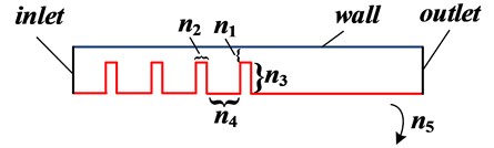
Fig. 3Three-dimensional model of the short labyrinth seal
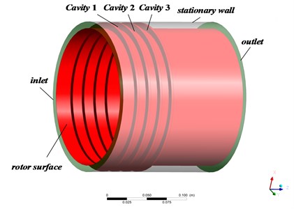
Fig. 4Mesh distribution for the short labyrinth seal
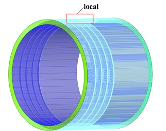
a) Global mesh density
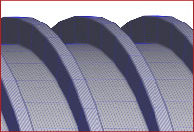
b) Local mesh density
3. Results and discussion
As shown in Fig. 1, the radial force tends to push the rotor center either towards or away from the seal center, while the tangential force tends to cause the rotor center to go into either a forward or a backward whirl motion around the seal center, depending upon its direction. According to the coordinate system used in the paper, the radial force pushes the rotor center towards or away from the seal center when is positive or negative, respectively. The radial force promotes a forward or a backward whirl of the rotor when is negative or positive, respectively. The directions of inlet preswirl and rotor rotation are defined using right-hand rule.
3.1. Verification of the numerical method
Table 3 gives the absolute fluid-induced forces based on experimental test, bulk flow method and present CFD method, respectively. For the two cases, CFD method performs much better to predict the fluid-induced forces than the bulk flow method. The maximum error for the CFD method is about 8.9 % compared with that of 44.6 % for the bulk flow method. It indicts that the present method is reliable.
Table 3Comparison of the fluid-induced force between published literature [15] and present results (N= 2025 rpm, Pin= 1.069 atm)
Fluid-induced force () | Exp. | Bulk flow (error) | CFD (error) | |
0.43, 0 m/s | 0.44 | 0.37 (15.9 %) | 0.42 (4.5 %) | |
0.095 | 0.11 (15.8 %) | 0.10 (5.3 %) | ||
0.31, 39.6 m/s | 1.12 | 0.62 (44.6 %) | 1.22 (8.9 %) | |
1.02 | 0.91 (10.8 %) | 1.08 (5.9 %) |
3.2. Influence of rotational speeds on the fluid-induced force
Fig. 5 shows the fluid-induced force variation as the rotational speed increases in case of 0.15, 0 m/s. For the tangential fluid-induced force, the negative tends to cause the rotor center to go into a forward whirl motion around the seal center in all computed rotational speed range. The tangential fluid-induced force increases almost linearly as the rotational speed increases, and the increase becomes more and more dramatic for higher inlet pressure. It should be noticed that the sign of the radial fluid-induced force changed as the rotational speed increases. performs to be positive and tends to push the rotor center towards the seal center when the rotational speed is less than about 20 000 rpm for 1.069 atm and 27 000 rpm for 1.093 atm. For other rotational speeds, performs to be negative and tends to push the rotor center away from the seal center. For the higher inlet pressure 1.093 atm, the radial fluid-induced force increases more dramatic. The magnitude of for 1.093 atm becomes greater than that for 1.069 atm again when the rotor crosses the transition speed range of 22 000 rpm-38 000 rpm approximately.
Fig. 5Fluid-induced force trend changes with the increasing rotational speed (E= 0.15, vt= 0 m/s)
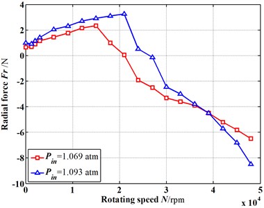
a) Radial fluid-induced forces vs. rotational speeds
b) Tangential fluid-induced forces vs. rotational speeds
Fig. 6 shows the pressure field inside the short labyrinth seal for 2 025 rpm. The pressure tends to decrease along the fluid flow direction due to the effect of the seal tooth. For other rotational speeds, the pressure variation shows almost the same trend.
Fig. 6Pressure field inside the seal (Pin= 1.093 atm, vt= 0 m/s)

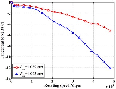
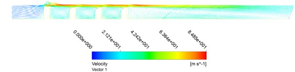
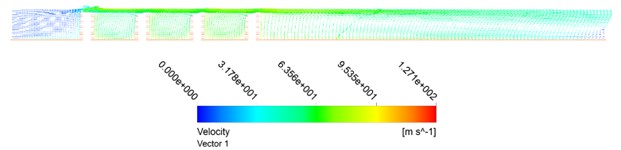
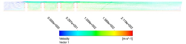
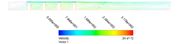
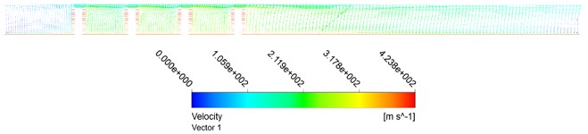
Fig. 7Velocity field through the seal (Pin= 1.093 atm, vt= 0 m/s)
a)2 025 rpm
b)6 000 rpm
c)12 000 rpm
d)20 000 rpm
e)30 000 rpm
f)40 000 rpm
Fig. 7 shows the velocity field through the seal for different rotational speeds. For lower rotational speeds (such as 12 000 rpm in this paper), it has relatively smaller influence on the flow field inside the seal. The vortexes in seal cavities can be seen clearly along the axial direction. As the rotational speed increases, its influence on the flow field becomes more and more dramatic. Part of the flow field is occupied by the circumferential flow due to the strong velocity near the rotor surface. The location of the maximum velocity inside the flow field changes from the seal clearance to the rotor surface.
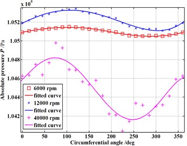
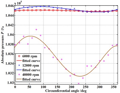
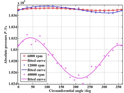
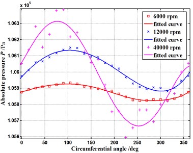
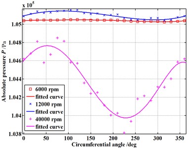
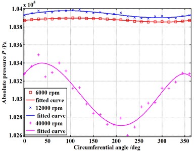
Fig. 8Pressure distribution in the circumferential direction of seal cavities (E= 0.15)
a) Cavity 1 (1.069 atm)
b) Cavity 2 (1.069 atm)
c) Cavity 3 (1.069 atm)
d) Cavity 1 (1.093 atm)
e) Cavity 2 (1.093 atm)
f) Cavity 3 (1.093 atm)
Fig. 8 shows the pressure distribution for different rotational speeds in the circumferential direction of the seal cavities (as shown in Fig. 3). The pressure in the circumferential direction of each seal cavity presents almost a sine distribution. The pressure fluctuation becomes more and more dramatic due to the increasing rotational speed. For each seal cavity, the circumferential angle corresponding to the peak pressure becomes smaller and smaller as the rotational speed increases. Take 1.093 atm as an example, the angle changes from about 105 degrees to 83 degrees for cavity 1. It indicates that the peak pressure location has a shift away from the minimum clearance location. This results in the sign change of the radial fluid-induced force with the increasing rotational speed, as shown in Fig. 5(a). Considering the axial direction, the circumferential angle corresponding to the peak pressure location changes from about 83 degrees in cavity 1 to 38 degrees in cavity 3 (take 40 000 rpm as an example). The effect of the rotational speed on the fluid-induced force becomes more remarkable for the longer seal with many cavities.
3.3. Influence of inlet preswirl on the fluid-induced force
where , and:
where , , is the adiabatic exponent of the fluid, is the specific gas constant.
Fig. 9Fluid-induced force trend changes with increasing inlet preswirl ratio (E= 0.15)
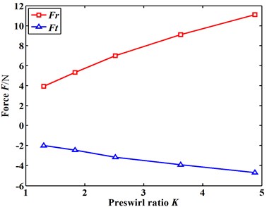
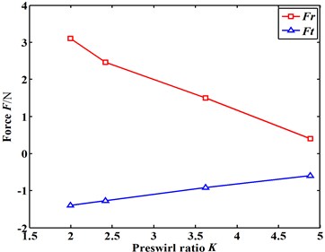
Fig. 9 shows the fluid-induced force trend changes as the inlet preswirl ratio K increases. The inlet preswirl ratio is defined as Eq. (1). It can be seen that both the radial and tangential fluid-induced force increase with the inlet preswirl ratio. The resulted negative tangential fluid-induced force indicts that the positive preswirl tends to promote the forward whirling motion of the rotor. It should be noted that the increasing inlet preswirl ratio leads to the increase of the inlet total pressure as well as the mass flowrate. The inlet total pressure and the mass flowrate will also either intensify or weaken the forward whirling motion of the rotor. Denecke [22, 23] analyzed the influence of preswirl and rotation on the labyrinth seal leakage, as well as presented the relationship among the above terms by the dimensional analysis. As shown in Eq. (2), an effective pressure ratio was used instead of pressure ratio to predict the mass flowrate and account for the influence of preswirl on the leakage.
To figure out the relationship between the preswirl and fluid-induced force, the inlet total pressure was kept as a constant value. Fig. 10 shows the influence of the preswirl ratio on the flow characteristics under the same inlet total pressure. It can be seen from Fig. 10(a) that both the radial and tangential fluid-induced force decrease with the increasing preswirl ratio. This is mainly because the effective pressure ratio, as well as the resulted mass flowrate decreases as the preswirl ratio increases.
Fig. 10Influence of the preswirl ratio on the flow characteristics under the same inlet total pressure: (E= 0.15, Pin= 1.093 atm)
a) Fluid-induced force vs. preswirl ratio
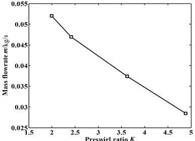
b) Mass flowrate vs. preswirl ratio
3.4. Analysis of combined influence due to rotational speeds and inlet preswirl
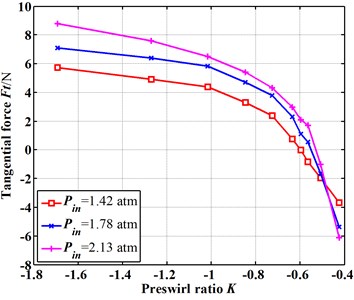
To improve the system stability, the negative preswirl that can offset the effect of rotor rotation is generally introduced at the inlet. Fig. 11 shows the influence of the negative preswirl on the tangential fluid-induced force at different inlet pressures. Take 1.42 atm as an example, a negative tangential fluid-induced force will be produced when the preswirl ratio is greater than –0.60. Conversely, the positive tangential fluid-induced forces will be produced when the preswirl ratio is less than –0.60. Here this preswirl ratio is named as the critical preswirl ratio which corresponds to zero tangential fluid-induced force. Because the sign of the critical preswirl ratio value will lead to different whirling motions of the rotor. For 1.78 atm and 2.13 atm, the critical preswirl ratio increases up to –0.55 and –0.52. It can be seen that a smaller magnitude of the negative preswirl ratio will be needed to offset the effect of rotational speeds for a higher inlet pressure. To obtain a same mass flowrate, it was known that a higher inlet pressure will be usually needed for long seals with many cavities compared with short seals. It indicts that the short seal generates relatively lower magnitude of the tangential force due to rotor rotation. The inlet preswirl generates a majority of the tangential force.
Fig. 11Influence of the negative preswirl on the tangential fluid-induced force (E= 0.15)
4. Conclusions
This paper analyzes the characteristics of the fluid-induced force for short labyrinth seals by CFD method. The CFD model demonstrates a good agreement with the published experimental results. The influence of rotational speeds and inlet preswirl are analyzed in eccentric conditions. The following points summarize the obtained results:
1) The tangential fluid-induced force increases almost linearly as the rotational speed increases, and the increase becomes more and more dramatic for higher inlet pressure. The sign of the radial fluid-induced force changed as the rotational speed increases. The radial fluid-induced force performs to be negative and tends to push the rotor center away from the seal center when the rotational speed is greater than about 20 000 rpm for 1.069 atm and 27 000 rpm for 1.093 atm. The magnitude of radial fluid-induced force for 1.093 atm becomes greater than that for 1.069 atm again when the rotor crosses the transition speed range of 22 000 rpm-38 000 rpm approximately.
2) The pressure in the circumferential direction of each seal cavity presents almost a sine distribution. The pressure fluctuation becomes more and more dramatic due to the increasing rotational speed. The peak pressure location has a shift away from the minimum clearance location as the rotational speed increases. This shift also exists in the axial direction. The effect of the rotational speed on the fluid-induced force becomes more remarkable for the longer seal with many cavities.
3) Because the effective pressure ratio, as well as the resulted mass flowrate decreases as the preswirl ratio increases, both the radial and tangential fluid-induced force decrease with the increasing preswirl ratio for the same inlet total pressure.
4) The critical preswirl ratio which corresponds to zero tangential fluid-induced force is calculated, and results show that a smaller magnitude of the preswirl ratio will be needed to offset the effect of rotational speeds at a higher inlet pressure. The inlet preswirl generates a majority of the tangential force for short labyrinth seals. This is significant for the shrouded turbine stages, because the strong preswirl will be produced by the downstream steam of previous stator stage. The results of this paper will apply to the relatively short labyrinth seals employed in the shrouded turbine stages where the seal teeth are on the rotor.
References
-
Benckert H., Wachter J. Flow induced spring coefficients of labyrinth seals for application in rotordynamics. NTRS, 1980, p. 189-212.
-
Rosic B., Denton J. D. Control of shroud leakage loss by reducing circumferential mixing. Journal of Turbomachinery – Transactions of The ASME, Vol. 130, 2008, p. 0210102.
-
Muszynska A., Bently D. E. Anti-swirl arrangements prevent rotor/seal instability. Journal of Vibration, Acoustics, Stress, and Reliability in Design, Vol. 111, Issue 2, 1989, p. 156-162.
-
Kim C. H., Lee Y. B. Test results for rotordynamic coefficients of anti-swirl self-injection seals. Journal of Tribology, Vol. 116, Issue 3, 1994, p. 508-513.
-
Soto E. A., Childs D. W. Experimental rotordynamic coefficient results for (a) a labyrinth seal with and without shunt injection and (b) a honeycomb seal. Journal of Engineering for Gas Turbines and Power – Transactions of The ASME, Vol. 121, Issue 1, 1999, p. 153-159.
-
Kim N., Park S. Y., Rhode D. L. Predicted effects of shunt injection on the rotordynamics of gas labyrinth seals. Journal of Engineering for Gas Turbines and Power – Transactions of The ASME, Vol. 125, Issue 1, 2003, p. 167-174.
-
Lv C., He L., Chen G., et al. Experimental Investigation on Suppressing Fluid-Induced Vibration in the Seal Clearance by Anti-swirl Flow. Lecture Notes in Mechanical Engineering, 2015, p. 109-117.
-
Kwanka K. Rotordynamic Impact of Swirl Brakes on Labyrinth Seals with Smooth or Honeycomb Stators. Orlando, Florida, 1997.
-
Kwanka K. Improving the stability of labyrinth gas seals. Journal of Engineering for Gas Turbines and Power – Transactions of the ASME, Vol. 123, Issue 2, 2001, p. 383-387.
-
Guinzburg A., Brennen C. E., Acosta A. J., et al. The effect of inlet swirl on the rotordynamic shroud forces in a centrifugal pump. Journal of Engineering for Gas Turbines and Power, Vol. 115, 1993, p. 193-287.
-
Robic B. F. Experimental and Numerical Analysis of the Effect of Swirl on the Pressure Field in Whirling Annular and Labyrinth Seals. Texas A&M University, 1999.
-
Nielsen K. K., Childs D. W., Myllerup C. M. Experimental and theoretical comparison of two swirl brake designs. Journal of Turbomachinery – Transactions of the ASME, Vol. 123, Issue 2, 2001, p. 353-358.
-
Brown P. D., Childs D. W. Measurement versus predictions of rotordynamic coefficients of a hole-pattern gas seal with negative preswirl. Journal of Engineering for Gas Turbines and Power – Transactions of the ASME, Vol. 134, 2012, p. 12250312.
-
Childs D. W., Mclean J. E., Zhang M., et al. Rotordynamic performance of a negative-swirl brake for a tooth-on-stator labyrinth seal. ASME Turbo Expo: Turbine Technical Conference and Exposition, Düsseldorf, Germany, 2014, p. V7A-V31A.
-
Rajakumar C., Sisto F. Experimental investigations of rotor whirl excitation forces induced by labyrinth seal flow. Journal of Vibration and Acoustics, Vol. 112, 1990, p. 515-522.
-
Hirano T., Zenglin G., Kirk R. G. Application of computational fluid dynamics analysis for rotating machinery – part II: labyrinth seal analysis. Transactions of the ASME, Journal of Engineering for Gas Turbines and Power, Vol. 127, Issue 4, 2005, p. 820-826.
-
Sreedharan S. S., Vannini G., Mistry H. CFD assessment of rotordynamic coefficients in labyrinth seals. ASME Turbo Expo: Turbine Technical Conference and Exposition, Düsseldorf, Germany: 2014, p. V7B-V32B.
-
Li Z., Li J., Feng Z. Numerical investigations on the leakage and rotordynamic characteristics of pocket damper seals-part I: effects of pressure ratio, rotational speed, and inlet preswirl. Journal of Engineering for Gas Turbines and Power – Transactions of the ASME, Vol. 137, 2015, p. 0325033.
-
Untaroiu A., Untaroiu C. D., Wood H. G., et al. Numerical modeling of fluid-induced rotordynamic forces in seals with large aspect ratios. Journal of Engineering for Gas Turbines and Power – Transactions of the ASME, Vol. 135, 2013, p. 0125011.
-
Pugachev A. O., Kleinhans U., Gaszner M. Prediction of rotordynamic coefficients for short labyrinth gas seals using computational fluid dynamics. Journal of Engineering for Gas Turbines and Power – Transactions of the ASME, Vol. 134, 2012, p. 0625016.
-
Moore J. J. Three-dimensional CFD rotordynamic analysis of gas labyrinth seals. Transactions of the ASME, Journal of Vibration and Acoustics, Vol. 125, Issue 4, 2003, p. 427-433.
-
Denecke J., Faerber J., Dullenkopf K., et al. Dimensional analysis and scaling of rotating seals. ASME Turbo Expo 2005: Power for Land, Sea, and Air, Reno-Tahoe, Nevada, USA, 2005.
-
Denecke J., Dullenkopf K., Wittig S. Influence of preswirl and rotation on labyrinth seal leakage. 10th International Symposium on Transport Phenomena and Dynamics of Rotating Machinery, Hawaii, 2004.
Cited by
About this article

Financial supports from National Natural Science Foundation of China (No. 11402148, 51275088, 51176129, 51276116), Innovation Key Program of Shanghai Municipal Education Commission (13ZZ120, 13YZ066) and USST Key Laboratory of Flow Control and Simulation (D15013) were sincerely acknowledged.
Prof. Yang (Jiangang Yang) gave many valuable suggestions on the setup of geometric model and CFD model. Prof. Li (Chun Li) provided the parallel computer for the numerical simulation of the article. Prof. Dai (Ren Dai) and Prof. Yang (Ailing Yang) gave many valuable suggestions on the linguistic issues and article structure.
