Thulasi Bikku* | Radhika Paturi
© 2019 IIETA. This article is published by IIETA and is licensed under the CC BY 4.0 license (http://creativecommons.org/licenses/by/4.0/).
OPEN ACCESS
Texture Combination is a process of re-sampling a smaller texture image to synthesize a new texture with similar appearance. This texture combination is weaved with Steganography to conceal secret text messages. In this paper, a novel texture combination based Steganographic method in frequency domain is proposed to hide and send secret messages. In contrast to the existing techniques, this method generates a Stego synthetic texture of arbitrary size rather than embedding in the original image. This method offers an embedding capacity that is proportional to the size of the Stego synthetic texture. Moreover its reversible capability allows recovering secret messages and the source texture. The texture combination is performed in frequency domain making use of Discrete Cosine Transform (DCT) which makes it almost impossible for a Steganalytic algorithm to defeat this approach. Experimental results verify that the proposed method provides various embedding capacities, produces visually good texture images and recover secret messages.
texture combination, steganography, embedding, steganalysis, discrete cosine transform
The tremendous growth in computational power and technologies for the past few decades has spurred a variety of security techniques. Steganography, meaning covered writing or protected writing is one such security technique [1]. It is the art of hiding secret content in a cover medium [2]. Steganography is divided into four main categories having various cover sources such as text, audio/video, image, protocol and a 3D image [3]. Image Steganography is further classified into two types based on the domain used to embed the message as spatial and frequency domain. In spatial domain method the secret message is directly embedded in the original pixels of the image whereas in frequency domain, embedding is done in transformed blocks. The common transforms employed to embed secret data are Discrete Cosine Transform (DCT), Discrete Fourier Transform (DFT) and Discrete Wavelet Transform (DWT). The ultimate aim of Steganography is to keep the presence of secret message undetectable, yet the invasive nature of the steganographic system reveals the existence of the secret content [4]. The major issues concerned in an effective Steganography are payload, robustness, imperceptibility and security.
Most of the image Steganographic algorithms make use of an existing image as cover medium. Embedding secret messages into the cover medium encounters a distortion in the resulting Stego image. These approaches have two main drawbacks. First, the fixed size of the cover image leads to more distortion if the embedding is high, consequently, compromising between the embedding capacity and image quality. Second, the distortion caused due to embedding makes it possible for the steganalytic algorithms to defeat the Steganographic system thus revealing the hidden message in the Stego image.
The proposed Steganographic method generates Stego synthetic texture, synthesized from a source texture.The size of the Stego synthetic texture is arbitrary, thus allowing various embedding capacities. The Stego synthetic texture is generated by processing in frequency domain technique with discrete cosine transform. The secret message is embedded by the process of texture combination in frequency domain. In reverse, the secret message and the source texture can be extracted from the Stego synthetic texture.
The organization of the paper as follows: Section 2 explains about the related work of the proposed method, section 3 clearly explains about the proposed method with algorithms, section 4 gives the information about the performance measures, Section 5 experimentally compared the proposed method with Kuo-Chen Wu method and the results show that proposed method is better than the existing method and finally section 6 concludes the paper.
Numerous amount of research works have been carried out in Steganography introducing techniques to hide the secret message. Qiang Cheng et al., [5] reported an additive approach to transform-domain information hiding and performance analysis for images and video. It has a good transparency and controls detection errors and provided a survey on steganography and steganalysis for digital images, mainly covering the fundamental concepts, the progress of steganographic methods for images in spatial representation and in JPEG format, and the development of the corresponding steganalytic schemes.
Y.K. Lee et al., [6] suggested a capacity evaluation method to estimate the maximum embedding capacity of each pixel. Imperceptibility is reported to be less in thistechnique. In [7], a technique called data masking is reported where instead of embedding a secret message into a multimedia object, the entire secret message to make it appear statistically similar to a multimedia object itself. This technique resists statistical attacks but has a processing overhead.
Yang Jie [8] introduced an algorithm for Image Information Hiding based on Anti-Arnold transform and Blending in DCT Domain. This method has a good imperceptibility but has only an average robustness. Jessica Fridrich [9] reported trade-off in steganography between number of embedding changes and their amplitude. The features of different transforms used in steganography that lead to detecting the information hiding are given in [10].
In [11] Cheng-Hsing Yang et al., suggested an adaptive LSB steganographic method using pixel-value differencing (PVD) that provides a larger embedding capacity and imperceptible stego images. But it could not withstand against statistical attacks. In [12] a family of stego-codes is generated from one covering code by combining Hamming codes and wet paper codes. This method makes decryption of secret content tough but not good against attacks.
Zhiyuan Zhang et al., [13] reported a two description image coding where the coarsely coded part is embedded into the finely coded part based on a least-significant bit steganographic method. But it has very less payload capacity. A high- capacity steganography scheme is reported by Liang Zhang et al., [14] for the JPEG2000 baseline system, which uses bit-plane encoding procedure twice to solve the problem due to bits’ stream truncation. But this method has a processing overhead.
A Technique for Image Steganography based on Block- DCT and Huffman Encoding is reported, which has high imperceptibility with minimum robustness. In Steganography Imaging System (SIS) wherein the algorithm uses binary codes and pixels inside an image. This method has an advantage of high payload capacity but suffers from imperceptibility.
Fangjun Huang et al., [15] reported a channel selection rule for steganography, with minimal detectable distortion for data hiding, by considering the perturbation error (PE), the quantization step (QS), and the magnitude of quantized DCT coefficient to be modified. In [19], an image steganography technique to hide multiple secret images and keys in color cover image using Integer Wavelet Transform (IWT) is reported.
Texture combination is an area of attention in computer vision and graphics. Recently it has also got attention in Steganography using either pixel based or patch based algorithms. Pixel-based algorithms [16] generate the synthesized image pixel by pixel and use spatial neighborhood comparisons to choose the most similar pixel in a sample texture as the output pixel. Since each output pixel is determined by the already synthesized pixels, any wrongly synthesized pixels during the process influence the rest of the result causing propagation of errors.
Otoriand Kuriyama [18] pioneered the work of combining data coding with pixel-based texture combination. Secret messages are encoded into colored dotted patterns and they are directly painted on a blank image. A pixel-based algorithm coats the rest of the pixels using the pixel-based texture combination method, thus concealing the existence of dotted patterns. To extract messages, the printout of the stego synthesized texture image is photographed before applying the data-detecting mechanism. The capacity provided by the method of Otoriand Kuriyama depends on the number of the dotted patterns. However, their method had a small error rate on the message extraction.
Patch-based algorithms paste patches from a source texture instead of a pixel to synthesize textures. This approach of Cohen et al. [20] and Xu et al. [21] improves the image quality of pixel-based synthetic textures because texture structures inside the patches are maintained. However, since patches are pasted with a small overlapped region during the synthetic process, an effort to ensure that the patches agree with their neighbors is to be made.
Liang et al. [24] introduced the patch-based sampling strategy and used the feathering approach for the overlapped areas of adjacent patches. Efros and Freeman [17] present a patch stitching approach called “image quilting.” For every new patch to be synthesized and stitched, the algorithm first searches the source texture and chooses one candidate patch that satisfies the pre-defined error tolerance with respect to neighbors along the overlapped region. Next, a dynamic programming technique is adopted to disclose the minimum error path through the overlapped region [23]. This declares an optimal boundary between the chosen candidate patch and the synthesized patch, producing visually plausible patch stitching.
Wu et al. [25] reported an image reversible data hiding algorithm which can recover the cover image without any distortion from the stego image after the hidden data have been extracted. Histogram shifting is a preferred technique among existing approaches of reversible image data hiding because it can control the modification to pixels, thus limiting the embedding distortion, and it only requires a small size location map, thereby reducing the overhead encountered. The current state-of-the-art for reversible image data hiding is the general framework suggested by Li et al. [22].
Recently Chen et al., [27] have reported a texture combination based Steganography, where the texture combination is message oriented. Kuo-Chen et al., [26] authors have utilized original pixels to perform patch based message oriented texture combination. This method is reversible and is more secure against certain geometric attacks and also produce varying sized stego synthetic textures, but this method is computationally complex since it involves computation of each pixel to obtain the stego synthetic texture.
In this proposed work the embedding procedure considers a source texture of arbitrary size and is initially split into equal sized patches of user defined size. The obtained patches are weaved into stego synthetic texture in first priority positions. The second priority positions are utilized only when we are under running of the first priority positions. The resultant image is termed as composition image.
Source texture: Source texture is a sample texture image of smaller size that is taken as input for the texture combination process. Its height and width are represented as Sh and Sw respectively.
Stego synthetic texture: Stego synthetic texture is defined as the message oriented texture synthesized from the source texture of user specified size. STw and STh are denoted as width and height of the Stego synthetic texture respectively.
Patch: Patch is the basic unit of the proposed Steganographic texture combination. It represents an image block of a source texture where its size is arbitrary. The height and width of a patch are denoted as Ph and Pw respectively. The number of patches present in the source texture is computed as,
$P_n=ST_W/P_W$ X $ST_h/P_h$ (1)
Candidate patch: Candidate patch is defined as a window of arbitrary size with height Ch and width Cw is employed to travel along the source texture by shifting a pixel following the scan line order to obtain the candidate patches.
The number of candidate patches for a given source texture can be derived using
$C_n=(S_W-C_W+1)×(S_h-C_h+1)$ (2)
Each candidate patch should be unique; else extraction may result in incorrect secret message.
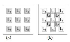
First priority positions: First priority positions are those positions of higher priority for combining patches fromsource texture in the Stego synthetic texture. The first priority positions can be derived as,
$L=S_W/2×S_h/2$ (3)
Second priority positions: Second priority positions are the positions of lower priority to combine patches from source texture in the Stego synthetic texture. The second priority positions are derivedusing,
$L_2=C_W/2×C_h/2$ (4)
The second priority positions come in between the first priority positions. The first and second priority positions are illustrated in Figure 1.
Figure 1. Illustration of priority positions to paste in the stego synthetic texture: (a) First priority positions, L1 (b) Second priority positions, L2
Composition image: Composition image is an intermediate image that contains source patches embedded in first and second priority positions. Figure 2 demonstrates composition images.
Figure 2. Composition images (a) Source patches at first priority positions (b) Source patches at first and second priority positions
3.1 Architecture
An index table is generated to record the positions where source patches are pasted. Next, the candidate patches are generated from the source texture by scanning it with a window of arbitrary size through each pixel [35]. The candidate patches are used to synthesize the Stego texture image. When placing candidate patches on the composition image, the area that is about to be synthesized is categorized into six overlapping regions, namely, ‘O’ shape, ’C’ shape, ‘L’ shape, downward ‘U’ shape, upward ‘U’ shape and ‘L’ shape with an isolated part. In this work, once the candidate patches are generated, they are subjected to discrete cosine transformation. On the other hand, the source patches are also treated with discrete cosine transform.
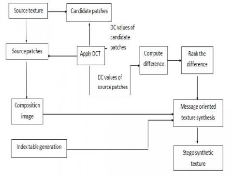
For each candidate patch that has to be synthesized in the Stego texture, the difference of DC values of candidate patches and its corresponding source patch DC value is computed. The differences are ranked and this ranking is taken as an equivalent of decimal value of the message that is to be embedded. The process is repeated for synthesizing the area around each weaved source patch to obtain the Stego synthetic texture. The embedding technique involved in this proposed work is presented in Figure 3.
Figure 3. Proposed message embedding scheme
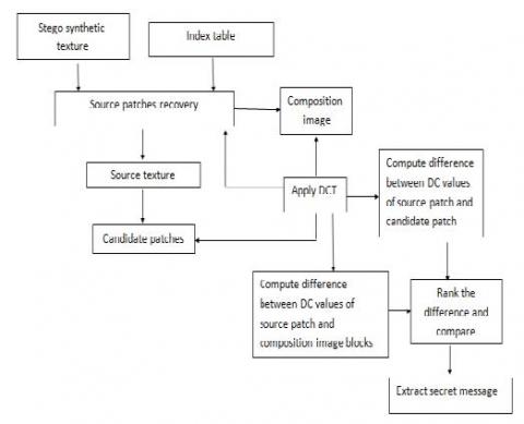
For extraction, the source patches are obtained from the Stego synthetic texture with the help of index table. Once the source patches are removed, the composition image can be obtained. The source patches are combined to retrieve the source texture after which the candidate patches are derived from the source texture. Discrete cosine transform is applied to the source patch and candidate patches. The patches in the composition image are also subjected to discrete cosine transformation. The difference between DC values of source patch and candidate patches are computed and ranked. The composition image patch with corresponding rank is matched and the rank gives decimal value of the secret message. The decimal values can be combined to extract the secret message. The extraction process, proposed in this work is presented in Figure 4.
Figure 4. Proposed message extraction scheme
3.2 Message embedding procedure
This section presents the message embedding process. The steps are described in detail in the following subsections.
3.2.1 Composition image and index table generation process
The input source texture is split into source patches of arbitrary size. An empty image of user specified size is taken and the source patches are weaved in the first priority positions and then in the second priority positions if necessary. In this proposed work the source patches are randomly seeded on the composition image to add security to the process. An index table corresponding to the composition image is generated and it contains the details about the position of each source patch. This index table plays a vital role in extraction process since it paves the way for message and source texture extraction. The number of entries in the index table can be determines as,
$In=(ST_n-C_h)/(C_w-P_d)+1X(ST_w-C_w)/(C_h-P_d)$ (5)
where STh and STw are the height and width of Stego synthetic texture, Ch and Cw are height and width of candidate patch and Pd is the patch depth.
3.2.2 Candidate patch generation process
Candidate patches are generated by scanning with a window of arbitrary size through each pixel of the source texture. These candidate patches are used to synthesize the area around source patches in composition image based on the rank that corresponds to the decimal equivalent of message that is to be hidden.
3.3 Discrete cosinetransform
A discrete cosine transform (DCT) expresses a finite sequence of data points in terms of sum of cosine functions oscillating at different frequencies. DCT is important to numerous applications in science and engineering, from loss compression of images to spectral methods for the numerical solution of partial differential equations. Discrete Cosine Transformation is widely used because of its high energy packing capability. Processing with the DC values naturally reduces the time complexity of the algorithm which may be high in direct pixel operations. The two dimensional DCT is given as
$\begin{align} & X{{k}_{1}},{{k}_{2}}=\sum\limits_{{{n}_{1}}=0}^{{{N}_{1}}-1}{\left( \sum\limits_{{{n}_{2}}=0}^{{{N}_{2}}-1}{x{{n}_{1}},{{n}_{2}}\cos \left[ \frac{\pi }{{{N}_{2}}}({{n}_{2}}+\frac{1}{2}){{k}_{2}} \right]} \right)}\cos \left[ \frac{\pi }{{{N}_{1}}}({{n}_{1}}+\frac{1}{2}){{k}_{1}} \right] \\ & =\sum\limits_{{{n}_{1}}=0}^{{{N}_{1}}-1}{\left( \sum\limits_{{{n}_{2}}=0}^{{{N}_{2}}-1}{x{{n}_{1}},{{n}_{2}}\cos \left[ \frac{\pi }{{{N}_{1}}}({{n}_{1}}+\frac{1}{2}){{k}_{1}} \right]} \right)}\cos \left[ \frac{\pi }{{{N}_{2}}}({{n}_{2}}+\frac{1}{2}){{k}_{2}} \right] \\\end{align}$ (6)
3.4 Message oriented texturecombination
The DC values obtained as a result of applying DCT to source patches and candidate patches are used for computing the difference. The difference of DC values of each candidate patches against each source patch is calculated and the differences are ranked. This candidate patch with a rank equivalent to the decimal value of the secret message is weaved in the overlapping region of each source patch. The area to be synthesized is filled with candidate patch each representing a character in message. This process thus accomplishes message oriented texture combination. The resultant image is the Stego synthetic texture which is ready to be sent to the receiver.
3.5 Message extractionprocedure
The first step in message extraction procedure is to recover the source patches and composition image from the Stego synthetic texture. In this proposed work the source patches are recovered with the help of index table that serves as a key between sender and receiver. Then the source patches are combined to get the source texture. Candidate patches are generated from the source texture. DCT is applied on source patches, candidate patches and the composition image patches. The difference of DC values of Source patch, candidate patch and source patch, composition image patch are computed. The computed differences are ranked and compared so that the ranks are taken as decimal values of the characters of the secret message. The secret message is extracted from the decimal values.
3.6 Algorithm
The steps involved in the embedding and extract ion procedures proposed in this work are presented as algorithms in this section.
Algorithm: Message embedding Procedure
Input: Source texture of arbitrary size and secret message.
Output: Stego synthetic texture.
Begin
Step 1: Split the source texture into equal sized source patches.
Step 2: Generate index table and composition image.
Step 3: Compute candidate patches from source texture.
Step 4: Apply DCT to candidate patches and source patches.
Step 5: Compute difference of DC values of candidate patches with each source patch.
Step 6: Rank the difference.
Step 7: Embed the candidate patches in overlapping regions around the source patches in compositionimage based on rank that is equivalent to the decimalvalue of secret message to obtain the Stego synthetic texture.
End
Algorithm: Message extraction Procedure
Input: Stego synthetic texture and Index table
Output: Secret message and source texture.
Begin
Step 1: Split the Stego synthetic texture into equal sized blocks based on the index table.
Step 2: With the help of index table, extract source patches andcomposition image.
Step 3: Rearrange source patches to form source texture.
Step 4: Generate candidate patches from source texture.
Step 5: Apply DCT on composition image, candidate patches and source patches.
Step 6: Compute difference of DC values of Source patch, candidate patch and source patch, compositionimage patch.
Step 7: Compare the difference and extract the corresponding rank that is the decimal equivalent of thecharacters of secret message.
End
The performance of the proposed method can be measured as:
4.1 Capacity
The embedding capacity of the proposed work is related with capacity in bits that can be concealed at each patch and is denoted as BEPP (Bits Embedded per Patch). The number of embeddable patches in the Stego synthetic texture is denoted as EPC (Embeddable Patch Count). The total capacity, Tc, of the Stego synthetic texture can be calculated from BEPP and EPC:
$EPC=SST_n-P_n$ (7)
where SSTn is the total number of patches in Stego Synthetic Texture and Pn is the number of source patches.
$T_c=BEPP×EPC$(8)
4.2 Quality of the Stego textureimage
The scheme that is adopted for measuring the quality of the Stego synthetic texture image is Pearson Product Moment Correlation (PPMC).It is a measure of how well two variables are related. The result of this measure is in the range [-1, 1].A result of 1 implies perfect correlation and a result in the range -1 to 1 indicates high correlation. The result -1 indicates poor correlation between the values.
$PPMC=(covX(X-Y))/σ_XXσ_Y$(9)
where cov is the covariance and σX, σY are the standard deviation of X and Y.
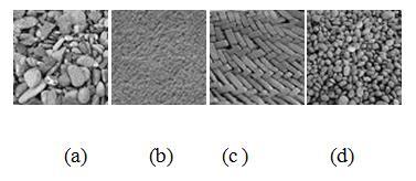
The proposed frequency domain Steganography with reversible texture combination has been experimented on more than 200 test images. Four such source texture images viz. Pebble, Metal, Basket and Stones which are of size (64x64) with pixel values in the range 0-255 are presented in Figure 5.
Figure 5. Source textures of size 64x64 (a) Pebble (b) Metal(c) Basket and (d) Stones
The input source texture image is partitioned into (8x8) non-overlapping blocks and is considered as the source patches. Next, an empty composition image is generated with same number of blocks as that of size of the secret message to be hidden. The source patches are weaved into the empty composition image with the help of index table. The index table contains details about location of each source patch for the reference of sender and receiver.
This index table also serves as key for the authorized receivers. Index table helps in determining the free locations available for embedding the secret message. Number of entries in the index table is computed as described in section 3.3.1. The corresponding composition images generated from the input source textures are presented in Figure 6. We did experiments for varying size of texture patterns and the resulting composition images.
Figure 6. Results of composition images generated from the source textures (a) Pebble (b) Metal (c) Basket and(d)Stones Next, the candidate patches of size(8x8) are generated from the source texture
DCT is applied on both source texture and candidate patches. The area to be synthesized around the source patches in composition image is categorized based on the six shapes. The difference of DC values of source patch and DC values of candidate patch are computed and are ranked as specified in section 3.3.4. The candidate patch with decimal equivalent of secret message is embedded in the composition image around the source patch. The process is repeated till the entire texture space is synthesized.
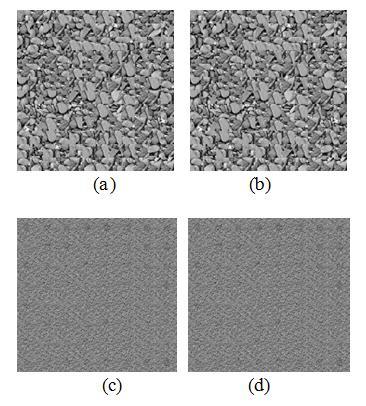
We conducted experiments of varying texture sizes, namely(128x128), (192x192), (256x256) and (512x512) and were synthesized with the proposed methodology for the source texture images shown in Figure 5.1 with an embedding capacity of 5 BEPP and 10 BEPP. The resulting Stego synthetic texture images generated by the proposed frequency domain Steganography with reversible texture combination of size (192x192) for Pebble source texture image with 5 bits embedded per patch and 10 bits embedded per patch are presented in Figure 7 (a) and (b). Figure 7 (c) and (d) are the Stego synthetic textures of size (192x192) generated from Metal source texture.
Figure 7. Results of Stego synthetic textures of size 192x192 with embedding capacity 5 BEPP and 10 BEPP (a) Pebble with 5 BEPP (b) Pebble with 10 BEPP (c) Metal with 5 BEPP (d) Metal with 10 BEPP
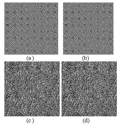
Figure 8 (a) and (b) presents Stego synthetic textures generated by the proposed technique of size (256x256) for Basket source texture image with 5bits embedded per patch and 10 bits embedded per patch. The Stego synthetic textures of size (256x256) generated from Stones source texture is presented in Figure 8 (c) and (d).
The embedding capacity of particular size of Stego synthetic texture image is fixed for all type of source texture images with a fixed window size of candidate patch. The source texture images under analysis of size (64x64) are split into 64 source patches each of size (8x8).
The window size of the candidate patches generated from the source texture images is also taken to be (8x8). Thus for an input image of size (64x64), the number of candidate patches obtained with window size (8x8) is 3249 as mentioned in equation (2).
Figure 8. Results of Stego synthetic texture of size256x256 with embedding capacity 5 BEPP and 10 BEPP (a) Basket with 5 BEPP (b) Basket with 10 BEPP (c) Stones with 5 BEPP (d) Stones with 10BEPP
In this experiment, the total number of embeddable patches are determined with the size of the Stego texture image that is about to be generated and number of source patches.
An embedding capacity of 960 bits, 2560 bits, 4800 bits and 20160 bits are observed for Stego texture images of size (128x128), (192x192), (256x256) and (512x512) with 5BEPP.
For 10 bits embedded per patch, an embedding capacity of 1920 bits, 5120 bits, 9600 bits and 40320 bits are obtained for Stego texture image combination of size (128x128), (192x192), (256x256) and (512x512) respectively. These observations on the proposed scheme are tabulated in Table 1.
Table 1. Total embedding capacity with the proposed steganography system
|
Input texture size= (64*64), Source patches (Pn)=64, Candidate patches (Cn)=3249, window size= (8*8) |
||||
|
Size of stego texture |
Count of patches in Stego synthetic texture, SSTn |
Embeddable Patch Count EPC |
Total capacity |
|
|
5BEPP |
10 BEPP |
|||
|
128*128 |
256 |
192 |
960 |
1920 |
|
192*192 |
576 |
512 |
2560 |
5120 |
|
256*256 |
1024 |
960 |
4800 |
9600 |
|
512*512 |
4096 |
4032 |
20160 |
40320 |
The efficiency of the proposed reversible texture combination based Steganography is measured in terms of computation time. When experimenting the proposed method on a 32 bit Intel core 2 Duo processor, a computation time of 7 sec, 9sec,13 sec and 25 sec was obtained for Pebble image of size (64x64)to generate Stego image of size(128x128),(192x192), (256x256) and (512x512) with 5 bits embedded per patch respectively. Similarly, for Metal image it is 7, 10, 12 and 24 seconds, for basket image it is 8, 9, 12 and 25 seconds and for Stones image it is 7, 9, 13 and 25 seconds to generate Stego image of size (128x128), (192x192), (256x256) and (512x512) with 5 bits embedded per patch respectively.
Table 2. Computational time (Seconds) with the proposed Steganography system for input images shown in Figure 5
|
Input source texture size (64*64) |
||||||||
|
Stego texture size |
5 BEPP |
10 BEPP |
||||||
|
Pebble |
Metal |
Basket |
Stones |
Pebble |
Metal |
Basket |
Stones |
|
|
128*128 |
7 |
7 |
8 |
7 |
15 |
14 |
15 |
15 |
|
192*192 |
9 |
10 |
9 |
9 |
22 |
22 |
21 |
22 |
|
256*256 |
13 |
12 |
12 |
13 |
29 |
28 |
28 |
28 |
|
512*512 |
25 |
24 |
25 |
25 |
36 |
36 |
34 |
35 |
For an embedding capacity of 10 bits per patch, the computation time taken for Pebble image is 15, 22, 29, 36 seconds, for Metal image it is 14, 22, 28, 36 seconds, for Basket image it is 15, 21, 28, 34 seconds and for Stones image it is 15, 22, 28, 35 seconds to generate Stego synthetic texture image of sizes (128x128), (192x192), (256x256) and (512x512) respectively. These computation times are tabulated in Table 2.
To determine the quality of the synthesized image, the proposed system is compared with the source texture using Pearson Product Moment Correlation (PPMC). A correlation coefficient of 0.8832, 0.89, 0.805 and 0.9 are obtained for 5 BEPP between the input source textures shown in Figure 5 (a), (b) and the Stego synthetic textures generated shown in Figure 7 (a), (c) and Figure 8 (a), (c) respectively. For 10 BEPP the correlation factors are observed to be 0.912, 0.8793, 0.95 and 0.867 between the input source textures shown in Figure 5 (c), (d) and the Stego synthetic textures generated shown in Fig 5.3 (b), (d) and Figure 8 (b), (d) respectively. The observed Pearson Correlation Coefficients are tabulated in Table 3.
Table 3. Comparison of Pearson correlation coefficients obtained with the proposed steganography technique
|
Texture |
Source VS Stego texture with 5 BEPP |
Source VS Stego texture with 10 BEPP |
|
Pebble |
0.8832 |
0.912 |
|
Metal |
0.89 |
0.8793 |
|
Basket |
0.805 |
0.95 |
|
Stones |
0.9 |
0.867 |
In order to measure the performance of the proposed Steganography system, we compare it with the existing spatial domain scheme reported by Kuo – Chen Wu et al., [31].
When experimented in the system of same configuration as mentioned in the above description, Kuo – Chen Wu method for Pebble input source texture image of size (64x64) takes a computation time of 385, 665, 851 and 1120 seconds to generate Stego synthetic texture of sizes(128x128), (192x192), (256x256) and (512x512) for embedding 5 bits per patch.
For embedding 10 bits per patch, time of 385, 644, 857 and 1126 seconds is consumed to synthesize texture images of size (128x128), (192x192), (256x256) and(512x512)respectively. These computation times are tabulated in Table 4.
Similarly the results of computation time comparison with existing and proposed method for the images Metal, Basket and stones of size (64x64) are tabulated in Table 5, 6 and 7 respectively. It is evident that the computation time is far less when compared to the existing one, since only one coefficient per patch is taken for computation rather that the entire set of pixels.
Table 4. Results of comparison on computation time by Kuo–Chen Wu method and the proposed method with 5 BEPP and 10 BEPP for Pebble source texture image of size (64x64)
|
Stego texture size |
5 BEPP |
10 BEPP |
||
|
Kuo- Chen Wu method |
Proposed method |
Kuo- Chen Wu method |
Proposed method |
|
|
(128*128) |
385 |
7 |
385 |
15 |
|
(192*192) |
665 |
9 |
644 |
22 |
|
(256*256) |
851 |
13 |
857 |
29 |
|
(512*512) |
1120 |
25 |
1126 |
36 |
Table 5. Results of comparison on computation time by Kuo–Chen Wu method and the proposed method with 5 BEPP and 10 BEPP for Metal source texture image of size (64x64)
|
Stego texture size |
5 BEPP |
10 BEPP |
||
|
Kuo- Chen Wu method |
Proposed method |
Kuo- Chen Wu method |
Proposed method |
|
|
(128*128) |
385 |
7 |
387 |
14 |
|
(192*192) |
664 |
10 |
648 |
22 |
|
(256*256) |
850 |
12 |
858 |
28 |
|
(512*512) |
1120 |
24 |
1127 |
36 |
Table 6. Results of comparison on computation time by Kuo-Chen Wu method and the proposed method with 5BEPP and 10 BEPP for Basket source texture image of size (64x64)
|
Stego texture size |
5 BEPP |
10 BEPP |
||
|
Kuo- Chen Wu method |
Proposed method |
Kuo- Chen Wu method |
Proposed method |
|
|
(128*128) |
384 |
8 |
386 |
15 |
|
(192*192) |
664 |
9 |
645 |
21 |
|
(256*256) |
850 |
12 |
857 |
28 |
|
(512*512) |
1121 |
25 |
1127 |
34 |
Table 7. Results of comparison on computation time by Kuo- Chen Wu method and the proposed method with 5BEPP and 10 BEPP for Stones source texture image of size (64x64)
|
Stego texture size |
5 BEPP |
10 BEPP |
||
|
Kuo- Chen Wu method |
Proposed method |
Kuo- Chen Wu method |
Proposed method |
|
|
(128*128) |
384 |
7 |
386 |
15 |
|
(192*192) |
665 |
9 |
647 |
22 |
|
(256*256) |
851 |
13 |
856 |
28 |
|
(512*512) |
1122 |
25 |
1126 |
35 |
The relevancy measure of the Stego synthetic texture image on the proposed work is compared with Kuo – Chen Wu method and the results are presented in Table 5.8. The quality of the Stego synthetic image obtained as a result of the proposed work is found to be in the range 0.8 to 0.9 which indicates a high correlation. The result produced by the proposed frequency domain method is slightly less than the existing method reported by Kuo – Chen Wu which works on spatial domain.
Table 8. Comparison of Pearson correlation coefficients time for Kuo – Chen Wu method and the proposed method with 5 BEPP and 10 BEPP
|
Texture |
Source VS Stego image with 5 BEPP |
Source VS Stego texture with 10 BEPP |
||
|
Kuo-Chen Wu method |
Proposed method |
Kuo-Chen Wu method |
Proposed method |
|
|
Pebble |
0.9992 |
0.8832 |
0.9974 |
0.912 |
|
Metal |
0.9990 |
0.89 |
0.9984 |
0.8793 |
|
Basket |
0.9982 |
0.805 |
0.9932 |
0.95 |
|
Stones |
0.9915 |
0.9 |
0.9916 |
0.867 |
In this paper a reversible texture combination based Steganography in frequency domain is proposed. This method is built on texture combination and discrete cosine transform as a platform to embed the secret message. Given a s mall source texture, this method produces a large Stego synthetic texture concealing secret messages. Patch based message oriented texture combination is adopted for synthesizing the Stego texture. This method is reversible and retrieves source texture and secret message perfectly. The presented method is secure and imperceptible. Also the computational overhead is less when compared to the existing methodologies. In contrast to the existing techniques, the proposed method generates Stego images rather than using the original image which makes it robust. It is evident from the experimental results that the quality of the Stego image is also good and thus concentrating on majority of the Steganographic issues.
We extend our sincere thanks to everyone who helped us in the realization of this work and we also thank Chairman of Vignan Institutions.
[1] Johnson NF, Jajodia S. (1998). Exploring steganography: Seeing the unseen. Computer 31(2): 26-34. http://dx.doi.org/10.1109/MC.1998.4655281
[2] Provos N, Honeyman P. (2003). Hide and seek: An introduction to steganography. IEEE Security and Privacy 99(3): 32-44. http://dx.doi.org/10.1109/MSECP.2003.1203220
[3] Cheng YM, Wang CM. (2006). A high-capacity steganographic approach for 3D polygonal meshes. The Visual Computer 22(9-11): 845-855. http://dx.doi.org/10.1007/s00371-006-0069-4
[4] Petitcolas FA, Anderson RJ, Kuhn MG. (1999). Information hiding-a survey. Proceedings of the IEEE 87(7): 1062-1078. http://dx.doi.org/10.1109/5.771065
[5] Cheng Q, Huang TS. (2001). An additive approach to transform-domain information hiding and optimum detection structure. IEEE Transactions on Multimedia 3(3): 273-284. http://dx.doi.org/10.1109/6046.944472
[6] Lee YK, Chen LH. (2000). High capacity image steganographic model. IEE Proceedings-Vision, Image and Signal Processing 147(3): 288-294. http://dx.doi.org/10.1049/ip-vis:20000341
[7] Radhakrishnan R, Kharrazi M, Memon N. (2005). Data masking: A new approach for steganography. Journal of VLSI Signal Processing Systems for Signal, Image and Video Technology 41(3): 293-303. http://dx.doi.org/10.1007/s11265-005-4153-1
[8] Yang J. (2010). Algorithm of image information hiding based on new anti-Arnold transform and Blending in DCT domain. In 2010 IEEE 12th International Conference on Communication Technology, pp. 312-315. IEEE. http://dx.doi.org/10.1109/ICCT.2010.5689227
[9] Fridrich J. (2006). Minimizing the embedding impact in steganography. In Proceedings of the 8th Workshop on Multimedia and Security, pp. 2-10. ACM. http://dx.doi.org/10.1145/1161366.1161369
[10] Pevný T, Fridrich J. (2006). Determining the stego algorithm for JPEG images. IEEE Proceedings-Information Security 153(3): 77-86. http://dx.doi.org/10.1049/ip-ifs:20055147
[11] Yang CH, Weng CY, Wang SJ, Sun HM. (2008). Adaptive data hiding in edge areas of images with spatial LSB domain systems. IEEE Transactions on Information Forensics and Security 3(3): 488-497. http://dx.doi.org/10.1109/TIFS.2008.926097
[12] Zhang W, Zhang X, Wang S. (2008). Maximizing steganographic embedding efficiency by combining Hamming codes and wet paper codes. In International Workshop on Information Hiding, 60-71. Springer, Berlin, Heidelberg. http://dx.doi.org/10.1007/978-3-540-88961-8_5
[13] Zhang Z, Zhu C, Zhao Y. (2008). Two-description image coding with steganography. IEEE Signal Processing Letters 15: 887-890. http://dx.doi.org/10.1109/LSP.2008.2006710
[14] Zhang L, Wang H, Wu R. (2009). A high-capacity steganography scheme for JPEG2000 baseline system. IEEE transactions on Image Processing 18(8): 1797-1803. http://dx.doi.org/10.1109/TIP.2009.2021544
[15] Huang F, Huang J, Shi YQ. (2012). New channel selection rule for JPEG steganography. IEEE Transactions on Information Forensics and Security 7(4): 1181-1191. http://dx.doi.org/10.1109/TIFS.2012.2198213
[16] Wei LY, Levoy M. (2000). Fast texture synthesis using tree-structured vector quantization. In Proceedings of the 27th Annual Conference on Computer Graphics and Interactive Techniques, pp. 479-488. ACM Press/Addison-Wesley Publishing Co.. http://dx.doi.org/10.1145/344779.345009
[17] Efros AA, Leung TK. (1999). Texture synthesis by non-parametric sampling. In Proceedings of the seventh IEEE International Conference on Computer Vision 2: 1033-1038. IEEE. http://dx.doi.org/10.1109/ICCV.1999.790383
[18] Otori H, Kuriyama S. (2009). Texture synthesis for mobile data communications.IEEE Computer Graphics and Applications 29(6): 74-81. http://dx.doi.org/10.1109/MCG.2009.127
[19] Bikku T. (2018). A new weighted based frequent and infrequent pattern mining method on realtime E-commerce. Information Systems Engineering 23(5): 121. http://dx.doi.org/10.3166/isi.23.5.121-138
[20] Cohen MF, Shade J, Hiller S, Deussen O. (2003). Wang tiles for image and texture generation. ACM Transactions on Graphics (TOG) 22(3): 287-294. http://dx.doi.org/10.1145/882262.882265
[21] Xu K, Cohen-Or D, Ju T, Liu L, Zhang H, Zhou S, Xiong Y. (2009). Feature-aligned shape texturing. ACM Transactions on Graphics (TOG) 28(5): 108. http://dx.doi.org/10.1145/1618452.1618454
[22] Li X, Li B, Yang B, Zeng T. (2013). General framework to histogram-shifting-based reversible data hiding. IEEE Transactions on Image Processing 22(6): 2181-2191. http://dx.doi.org/10.1109/TIP.2013.2246179
[23] Bikku T, Nandam SR, Akepogu AR. (2018). A contemporary feature selection and classification framework for imbalanced biomedical datasets. Egyptian Informatics Journal 19(3): 191-198. http://dx.doi.org/10.1016/j.eij.2018.03.003
[24] Liang L, Liu C, Xu YQ, Guo B, Shum HY. (2001). Real-time texture synthesis by patch-based sampling. ACM Transactions on Graphics (ToG) 20(3): 127-150. http://dx.doi.org/10.1145/501786.501787
[25] Wu HT, Dugelay JL, Shi YQ. (2015). Reversible image data hiding with contrast enhancement. IEEE Signal Processing Letters 22(1): 81-85. http://dx.doi.org/10.1109/LSP.2014.2346989
[26] Wu KC, Wang CM. (2015). Steganography using reversible texture synthesis. IEEE Transactions on Image Processing 24(1): 130-139. http://dx.doi.org/10.1109/TIP.2014.2371246
[27] Chen J, Lu W, Fang Y, Liu X, Yeung Y, Xue Y. (2018). Binary image steganalysis based on local texture pattern. Journal of Visual Communication and Image Representation 55: 149-156. http://dx.doi.org/10.1016/j.jvcir.2018.06.004