Shuruq A. Al-Khafaji*![]() | Amjed H. Saleh
| Amjed H. Saleh![]() | Saba M. Shaheed
| Saba M. Shaheed![]()
©2023 IIETA. This article is published by IIETA and is licensed under the CC BY 4.0 license (http://creativecommons.org/licenses/by/4.0/).
OPEN ACCESS
Suspension systems are crucial for enhancing passenger comfort, steering stability, and overall ride quality. They should also ensure effective directional control during handling manoeuvres and adeptly insulate passengers from external disturbances. In this study, a comparative evaluation was conducted between the Firefly Algorithm (FA) and Particle Swarm Optimisation (PSO) for optimising proportional-integral-derivative (PID) controllers in active suspension systems. Both algorithms, inspired by natural phenomena, have been previously successful in addressing diverse problems. By employing a mathematical model of the active suspension system and the MATLAB Simulation Toolbox, the behaviour of the system under these two optimisation techniques was investigated. The primary objective was to minimise the acceleration of the sprung mass in response to varied driving conditions. Results from the simulation process suggested a notable superiority of the FA over PSO when integrated with the PID controller, particularly in reducing the acceleration of sprung masses.
ride comfort, active suspension system, proportional-integral-derivative controller, optimisation, Particle Swarm Optimisation, Firefly Algorithm
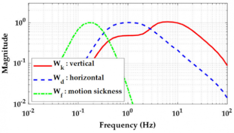
Suspension systems provide a fundamental link between a vehicle's structure and its tyres. Among the main principles in vehicle engineering lies the need for passenger comfort, particularly minimizing disturbances caused by external vibrations. Such vibrations can emanate from multifarious causes, such as braking, engine operation, and unpaved roads. Referring to ISO2631-1 [1], Figure 1 indicates the frequency weightings that demonstrate human body susceptibility to vibrations. It is seen that the 0.5-2 Hz on the horizontal axis and 4-10 Hz on the vertical axis are the areas where the human body shows the most sensitivity. Therefore, to elevate ride comfort, efforts should concentrate on reducing the accelerations of the sprung mass, specifically within the 4-10 Hz range [2].
Figure 1. Specified frequency weightings in ISO 2631-1 [2]
Vehicle suspensions can largely be categorised based on operational principles. The initial category is the passive suspension system, constructed predominantly from dampers and springs. When integrated with electric, hydraulic, or pneumatic devices, this system evolves into an active suspension. Challenges pertaining to active vehicle suspension systems predominantly surround the need for reliable control strategies. Such strategies must effectively modulate hydraulic actuators to deliver optimal suspension characteristics, whilst concurrently accounting for model uncertainties, parameter variations, and erratic feedback readings [3]. A distinctive capability of active suspensions, not seen in traditional passive systems, is the ability to introduce energy into the system [4]. Typically, in active suspension configurations, actuators are aligned in parallel with the spring and shock absorber components. The core philosophy of active suspension control rests in the deployment of requisite forces between the vehicle's body and the wheel axle through an active element, commonly recognised as the actuator.
In recent years, active suspension systems have been the subject of a wide variety of investigations. Many of these examinations have applied various approaches to the PID controller, owing to its cost-effectiveness, reliability and suitability for many usages. For example, attempts to nullify sprung mass acceleration, suspension deflection and tyre deflection led to the production of the H-infinity control system for actuator time-delayed active suspension systems [5]. A separate study [6] proposed the construction of a disturbance observer-based sliding mode controller in order to increase the efficacy of the vehicle's active suspension system when it comes to sprung mass displacement and acceleration. The aim of this exercise was to diminish body displacement and vibrational duration following exposure to exterior disruptions. Subsequently, a robust controller, a fractional order controller with PID, was formulated to mitigate the effects of such perturbations and optimised using Whale Optimisation Algorithm (WOA) and the PSO methodology [7]. On the opposite end of the spectrum, contrasting studies have explored fuzzy logic controllers (FLC) for vehicular suspensions, revealing a superior performance of FLC compared to other approaches [8]. In a groundbreaking study, an active suspension quarter was built using the first adaptive control method. This particular effort used an approximation dynamic programming (ADP) algorithm. This study highlighted the widespread use of linear control techniques in the field [9]. Subsequently, the introduction of the PID method was reported for the first time for a three-dimensional impact dynamics model [10]. indicating significant progress in the field. Advances in this field have not only incorporated sophisticated control techniques, but also for systems equipped with two hydraulic systems, it has been demonstrated that such devices this ability to independently operate two components provides high efficiency compared to other systems, as described by Nguyen [11]. Such innovations are essential in exploiting the infinite advantages of modern algorithms, which have implications for cost reduction and time efficiency in design and testing. The development of the field is evident, as exemplified by Rodriguez-Guerra et al. LPV) method used it is shown that the constantly changing parameters of this method are consistent with the selected model [12]. At the same time, stronger control mechanisms have been found to help reduce vehicle vibration [13]. Generally, artificial neural network (ANN)-based algorithms have been shown to enhance control process stability [14, 15]. In the realm of active suspension control, a unique method was developed that fuses a PID controller with a fuzzy neural network. The primary optimisation focus of this method lies in body acceleration, with real-time adjustments made to the parameters of the PID controller [16]. A specific method is introduced for active suspension systems using a fuzzy sliding mode control (SMC) method motivated by bionic nonlinear dynamics [17 that concludes by taking advantage of the nonlinear stiffness damping properties of the biomimetic reference model a are used efficiently Despite its energy efficiency performance, an adaptive neural network output feedback control case of a quarter car active suspension system was investigated [18].
Research efforts have expanded in the area of control algorithms used for active suspension systems. One such study introduced a linear quadratic regulator (LQR) control algorithm, where an in-loop optimization procedure was used to optimize the parameters of the LQR controller Another work used a dynamic model with multiple parameters [19] to simulate vehicle oscillations in the four-way surface excitation scenarios [20] in this regard The study also laid the foundation for adaptive fuzzy sliding mode proportional (AFSP) control solutions for active suspension systems. Another notable approach focused on adaptive extended Kalman estimation filtering (AEKF-UI) without known inputs, with an explicit relationship between parking and road complexity as its cornerstone on the reference [21]. An active suspension test system was also established, in which stiffness and damping properties of front and rear suspensions were evaluated under various conditions [22]. The test used an A-level road power spectrum as an input excitation. Subsequently, Min et al. [23] introduced an adaptive fuzzy optimal controller with dynamic capabilities for active suspension systems. Lastly, Mustafa et al. [24] proposed a PSO-based model-free fuzzy intelligent PID controller, further advancing the field.
The present study focuses on the development of a PID controller optimized by FA and PSO. The PSO-PID, FA-PID, and uncontrollable schemes are compared. PID controllers, as designed, have fast and consistent power delivery, characterized by reduced error, steady-state error elimination, reduced overshoot and oscillations Key metrics for measuring suspension systems no efforts include spring mass acceleration, displacement, suspension deflection and tire acceleration Finally bound metrics are After this introduction, the analysis goes into detail on the numerical examples in Section 2. Section 3 covers the development of PID controller with optimization -communicated using FA and PSO capabilities. Finally, Section 4 presents simulation results and insights gained from the implemented controller.
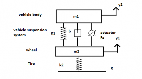
A detailed mathematical model was established in order to optimize the PID control system of the active suspension system. The active suspension system consisting of actuators along with springs and dampers was thoroughly investigated. It was found that the necessary energy is applied in the suspension system to reduce unwanted vibrations. A quarter-car model, as illustrated in Figure 2, provides a detailed schematic representation.
Figure 2. Quarter-car suspension system
Utilising Newton's fundamental laws of motion coupled with the free body diagram technique, a mathematical model for a quarter-car active suspension system was formulated [25]. This model is governed by the following equations:
$\sum F=m a$ (1)
$m_1 \ddot{y}_1=-k_1\left(y_1-y_2\right)-b\left(\dot{y}_1-\dot{y}_2\right)$ (2)
The Laplace transform was subsequently applied to Eq. (2), yielding:
$m_1 s^2 y_1(s)=-k_1\left(y_1(s)-y_2(s)\right)-b\left(s y_1(s)-s y_2(s)\right)$ (3)
$\left(m_1 s^2+b s+k_1\right) y_1(s)-\left(b s+k_1\right) y_2(s)=0$ (4)
$y_2(s)=\frac{\left(m_1 s^2+b s+k_1\right) y_1(s)}{\left(b s+k_1\right) y_2}$ (5)
$m_2 \ddot{y}_2=k_1\left(y_1-y_2\right)+b\left(\dot{y}_1-\dot{y}_2\right)+k_2\left(y_2-x\right)$ (6)
Further, the Laplace transform was also employed for Eq. (6), resulting in:
$m_1 s^2 y_2=k_1\left(y_1(s)-y_2(s)\right)-b\left(s y_1(s)+s y_2(s)\right)+X(s)$ (7)
$\left(m_1 s^2+b s+k_1+k_2\right) y_2(s)-\left(b s+k_1\right) y_{1(s)}=k_2 X(s)$ (8)
$\left(m_1 s^2+b s+k_1+k_2\right) \frac{\left(m_1 s^2+b s+k_1\right) y_1(s)}{\left(b s+k_1\right) y_2}-\left(b s+k_1\right) y_1=k_2 X(s)$ (9)
$\frac{y_{1(s)}}{x(s)}=\frac{k_2\left(b s+k_1\right)}{\left(m_2 s^2+b s+k_1+k_2\right)\left(m_1 s^2+b s+k_1\right)-\left(b s+k_1\right)^2}$ (10)
$G(s)=\frac{2.4 e 08 s+2.56 e 09}{12500 s^4+450000 s^3+4.48 e 07 s^2+2.4 e 08 s+2.56 e 09}$ (11)
In this representation, X(s) denotes the control effort, while y1 and y2 signify the vertical displacements of the tyre and sprung mass respectively. Table 1 offers a detailed account of the parameters [26] considered for this quarter vehicle active suspension system model.
Table 1. Parameters of the quarter vehicle active suspension system [26]
|
Notation |
Description |
Value |
Unit |
|
M1 |
Sprung mass |
250 |
kg |
|
M2 |
Unsprung mass |
50 |
kg |
|
K1 |
Spring stiffness |
16,000 |
N/m |
|
K2 |
Tyre stiffness |
160,000 |
N/m |
|
b |
Damping coefficient |
1,500 |
N.s/m |
3.1 PSO-based optimisation for PID control parameters
PSO emerged as a compelling intelligent swarm optimisation technique, inspired by the natural behaviours observed in flocks of birds. The inception of PSO is attributed to Kennedy, Eberhart, and Shi. Within the PSO algorithm, every particle in the population is orchestrated to gravitate towards the currently superior particle at a specific velocity. This gravitation seeks to discern the optimal solution among the available alternatives. Owing to its pronounced convergence properties and parallel global search capabilities, PSO frequently discovers the global optimum, adeptly addressing formidable optimisation challenges [26, 27]. The effectiveness of a control system is heavily influenced by the interaction among the particles, and their associated fitness values, as determined through the amalgamation of the PSO method and a pertinent simulation model [28].
Compared to other population-centric stochastic optimisation algorithms such as the genetic algorithm (GA) and Ant Colony Optimisation (ACO), PSO often exhibits comparable, if not superior, search performance for a myriad of optimisation quandaries. PSO's primary merits lie in its straightforward implementation, rapid convergence to satisfactory solutions, and efficacy. Nonetheless, PSO is not without limitations. For instance, a definitive convergence guarantee is absent. Given its stochastic nature, the algorithm can become ensnared in a local optimum, potentially missing the global pinnacle. Furthermore, the sensitivity of PSO to parameter selection poses difficulties. The inertia weight, which plays a crucial role in determining how much particles' ideal placements affect their movements, requires careful calibration. An excessive level of inertia might cause stagnation. However, a minimal level of it leads to unpredictable particle movements. Both of these situations limit the thorough exploration of the search domain. PSO's convergence speed has been found to be limited, especially in search spaces with several dimensions. The delayed convergence of the PSO method can be linked to the limited knowledge that each particle holds about the search space. It is a result of the system's fundamental architecture. To implement PSO, it is necessary to initialise a group of particles with random positions and velocities within the specified search area. The following steps consist of evaluating the fitness of each particle, updating the best positions for both individual particles and the entire swarm, modifying the velocity of each particle based on the optimal positions, and repeating this process until a specified termination condition is satisfied.
$v_{i+1}=w * v_i+c_1 r_1\left(\right.$ pbest $\left.-x_i\right)+c_2 r_2\left(\right.$ Gbest $\left.-x_1\right)$ (12)
$x_{i+1}=x_i+v_{i+1}$ (13)
The PSO algorithm's core variables include the inertia weight (w), which enhances search stability, alongside the cognitive (c1) and social coefficients (c2), with the former regulating the retention of a particle's initial velocity (v), and the latter two influencing the extent to which a particle is swayed by its own optimum position and that of its neighbours. The equilibrium between exploration and exploitation, pivotal for discerning the global optimum, is modulated by these variables. Random values, r1 and r2, fall within the [0-1] range. The terms pbest and Gbest correspond to the finest individual and collective particle positions in the swarm, while xi represents the current position. Eq. (12) computes the new particle velocity given the prior velocity and the positional discrepancy with the optimum, whereas Eq. (13) facilitates the particle's trajectory towards a new position. The prowess of a particle is evaluated via its fitness function, enabling the pursuit of the finest global and local positions, reflected in diverse PSO performance metrics. Table 2 lists the settings for the PSO algorithm.
Table 2. Configuration parameters for the PSO algorithm
|
Swarm Size |
20 |
|
Maximum iterations |
100 |
|
Problem dimension (kp, ki and kd) |
3 |
|
Cognitive acceleration (c2) |
1.4 |
|
Social acceleration (c1) |
1.2 |
|
Inertial weight (w) |
0.9 |
3.2 Description of the FA
The FA has been recognized in recent literature as a prominent method within evolutionary computation, primarily attributed to its transparent evolutionary mechanism, minimal parameter requirements, and notable efficacy in low-dimensional searches. A surge in interest in FA has led to its application in a plethora of domains. Notably, Chatterjee et al. demonstrated superior performance of the FA over the Artificial Bee Colony (ABC) algorithm in the realm of antenna design optimisation [29]. Elsewhere, the FA was successfully integrated for tuning the adaptive network-based fuzzy inference system (ANFIS) and PID controllers in managing water discharge levels in tanks [30]. Furthermore, the PID controller parameters within an Automatic Voltage Regulator (AVR) system were optimised using the FA [31]. Essentially, PID controller gains were adjusted during the FA's optimisation process to enhance control performance under typical conditions. Via this algorithm and subsequent simulations, attempts were made to refine the PID parameters: kp, ki and kd.
Yang is credited with the development of FA, which was modeled on the basis of flame behavior and light-beam patterns, and is a population-based method [32] Each firefly generates a specific heat pattern that serves two purposes: attraction and communication. The absorbance is determined by the inherent brightness of the flame associated with the specified objective function. In this algorithm, each flame occupies the position x=(x1..., xd), the attraction value, the deviation (x) in the segment d-dimensional field, which corresponds to the function f(x) and then in form on the opposite light intensity I(x) is absorbed for the other fireflies ( . It is functional to evaluate f x) as depicted in Eq. (14) [33, 34].
$I=I_e e^{-\gamma r}$ (14)
where, γ denotes the light absorption coefficient, and I0 represents the initial light intensity. Given the inverse relationship between a firefly's allure and its perceived brightness by other fireflies, the attractiveness β is defined as:
$\beta(r)=\beta_0 e^{-\gamma r^2}$ (15)
In this context, β symbolises the attractiveness at r=0, while Eq. (15) depicts the attractiveness's variation β0 with distance r. Predicated upon these, an initial solution is proposed by Eq. (16):
$X_j=r$ and $\left(U_b-L_b\right)+L_b$ (16)
where, upper and lower boundaries are denoted by Ub and Lb respectively. Eq. (17) provides an illustration of a firefly's trajectory towards another more luminous firefly.
$X_i^{r+1}=X_i^r+\beta_0 e^{-\gamma r_{i j}^2}\left(X_j-X_i\right)+\alpha \varepsilon_i$ (17)
where, Xi and Xj delineate the distance between any two fireflies. The parameters implemented in this study associated with the firefly are exhibited in Table 3.
Table 3. Parameters of the FA
|
Parameter Name |
Value |
|
Firefly size |
20 |
|
Max generation |
100 |
|
Alpha ($\alpha$) |
0.25 |
|
Beta ($\beta$) |
1 |
|
Gamma ($\gamma$) |
0.2 |
|
Lower bounded (Lb) |
[5000,100,0] |
|
Upper bounded (Ub) |
[10000,1000,1000] |
The parameter α was identified as being of paramount significance. Experimental sets were conducted, varying its value from 0 to 1 in increments of 0.25, culminating in an optimal value of 0.25. γ is the subsequent pivotal parameter, with its range typically spanning from 0.01 to 100 [35]. The final noteworthy parameter is the population size N, with experimental sizes extending from 100 to 1,000.
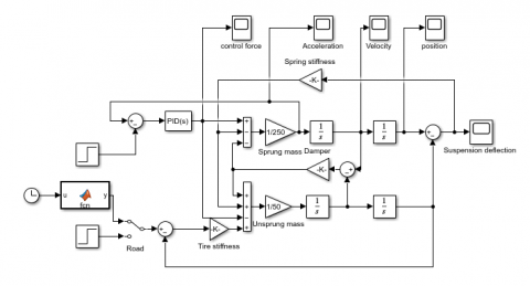
The research foundation for this study was derived from a vehicle described in a previous study. The parameters listed in Table 1 were derived from the standard values associated with that study. Figure 3 shows a schematic diagram of the quarter driving system. This model includes two full bodies, representing fourth wheels and wheels, with a combination of lumped characteristics that provide suspension and tire stiffness and damping Single bumps were chosen for the road profile, which was similar the size of the true path system [36]. The perturbation on the road, induced by this bump, can be represented by Eq. (18).
$R_d=\left\{\begin{array}{l}\frac{A}{2}\left(1-\cos 2 \pi\left(\frac{1}{T_b}\right) \text { for } T_b \leq t \leq 2 T_b\right. \\ 0 \quad \text { Otherwise }\end{array}\right.$ (18)
where, A signifies the height of the bump, set at 0.05m, and Tb denotes its duration, which lies in the range between 0.5 and 0.75 seconds. Figure 3 portrays a road profile characterized by a single bump.
Figure 3. Simulink model of the active suspension system for quarter-cars
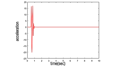
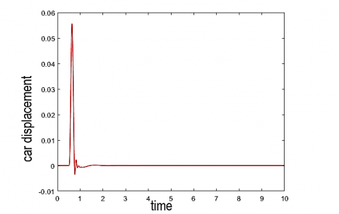
Next, a dynamic simulation of the four-vehicle system was performed, clarifying the dynamic response of the system, affected by changes in the error signal including suspension deflection, acceleration, and car body displacement about, and the input was adjusted to match the default specification or set point. The displacement of the vehicle body was used as a feedback mechanism for calibration purposes, aiming to generate the required hydraulic actuator force. Figures 4, 5, and 6 elucidate the velocity, acceleration, and displacement of the car body in relation to the system devoid of a controller, respectively.
Figure 4. Temporal response of vehicle velocity
The apparent oscillatory instability of the system was attributed to changes in the response. The main objective of the implementation system was to ensure consistent operational capability of the vehicles despite variations in the route. The PID auto-tuner was found to be insufficient to be a reliable controller for the active suspension system under study. Instead, FA and PSO methods were used to determine the optimal PID parameters.
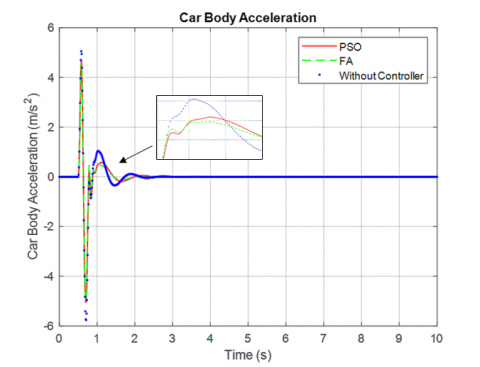
Figure 5. Temporal response of vehicle body acceleration
Figure 6. Temporal response of car displacement
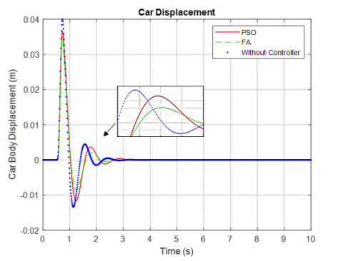
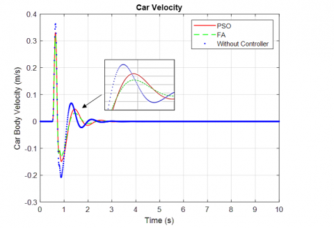
In the MATLAB/Simulink environment, a one-bump road profile was modelled for the active suspension system equipped with a PID controller. Tables 2 and 3 elucidate the parameter tuning results for the proposed controller using both the FA and PSO algorithms. A disturbance magnitude of 0.05m was set for the single bump. Figures 7, 8, and 9 depict the time-domain response of vibrations experienced by the passenger seat in a vertical orientation, drawing comparisons between controlled and uncontrolled scenarios.
Figure 7. Response of car displacement body
Figure 8. Response of car body velocity
Figure 9. Response of car body displacement
Post-optimisation, a discernible reduction in amplitude oscillations in the controlled system was observed, as evidenced in Figures 7, 8, and 9. The PID controller, fine-tuned using FA and PSO approaches, exhibited diminished overshoot values and reduced settling times across parameters, such as sprung mass acceleration (indicative of passenger comfort), displacement, and vehicle velocity, in contrast to the uncontrolled system. Table 4 enumerates the percentage decrease in peak values for each parameter for the one-bump disturbance.
Table 4. Reduction of overshoot levels for a single input
|
Parameter Amplitudes |
Reduction with PSO-PID Controller |
Reduction with FA-PID Controller |
|
Car body displacement (m) |
18.09% |
53.19% |
|
Car velocity |
32.3% |
54.42% |
|
Car body acceleration |
44.2% |
55.75% |
The graphical representations substantiate that the PID controller, augmented with PSO and FA, enabled the controlled variable to approach its set point within approximately two seconds. Notably, the suspension performance indices, particularly suspension dynamic travel and vertical acceleration, witnessed significant enhancement both pre and post-optimisation. It was determined that the PSO and FA algorithms hold considerable promise for application in suspension control. In direct comparisons, the FA-optimised control demonstrated a superior performance over the PSO-optimised PID controller. This superiority of the FA algorithm suggests potential improvements in vehicle handling dynamics.
The suspension system stands as a pivotal component of a vehicle, instrumental in mitigating vibrations and impacts from uneven road terrains while transmitting force. For the quarter-car active suspension model under investigation, a PID controller was optimised using the FA and PSO. It was observed that with an increment in the number of iterations for both the FA and PSO algorithms, there was a significant reduction in the sprung mass displacement: 18.09% with PSO and 53.19% with FA. Similarly, car body acceleration witnessed a reduction of 44.2% with PSO and 55.75% with FA. These outcomes highlight enhanced system dynamic responsiveness, specifically in the displacement of the car body, an indicator of passenger comfort and vehicular stability.
Future avenues of study are proposed to investigate hybrid algorithms, encompassing combinations such as FA combined with grey wolf optimisation (FA+GWO), FA combined with PSO (FA+PSO), and FA combined with ABC (FA+ABC). Such hybrids promise to amalgamate the strengths of individual optimisation techniques, potentially circumventing their inherent limitations. Employing these multi-strategy approaches could facilitate a more expansive exploration of search spaces, thereby diminishing the risk of converging to local optima. Additionally, the synergistic employment of diverse optimisation strategies might streamline the search, cutting down computational time. This aspect is particularly critical, given that extended computation remains a significant impediment in such studies.
We would like to express our sincere appreciation to the authors whose works on FA and PSO algorithms have appeared in numerous papers and conference proceedings.
[1] ISO. (1997). ISO 2631-1:1997 Mechanical vibration and shock evaluation of human exposure to whole-body vibration, Part 1: General requirements. International Organization for Standardization.
[2] Rimell, A.N., Mansfield, N.J. (2007). Design of digital filters for frequency weightings required for risk assessments of workers exposed to vibration. Industrial Health, 45(4): 512-519. https://doi.org/10.2486/indhealth.45.512
[3] Karam, Z.A., Awad, O.A. (2020). Design of active fractional PID controller based on whale's optimisation algorithm for stabilizing a quarter vehicle suspension system. Periodica Polytechnica Electrical Engineering and Computer Science, 64(3): 247-263. https://doi.org/10.3311/PPee.14904
[4] Priyandoko, G., Mailah, M. (2007). Simulation of suspension system with adaptive fuzzy active force control. International Journal of Simulation Modelling, 1: 25-36. https://doi.org/10.2507/IJSIMM06(1)3.079
[5] Du, H., Zhang, N. (2007). H∞ control of active vehicle suspensions with actuator time delay. Journal of Sound and Vibration, 301(1-2): 236-252. https://doi.org/10.1016/j.jsv.2006.09.022
[6] Deshpande, V.S., Mohan, B., Shendge, P.D., Phadke, S.B. (2014). Disturbance observer based sliding mode control of active suspension systems. Journal of Sound and Vibration, 333(11): 2281-2296. https://doi.org/10.1016/j.jsv.2014.01.023
[7] Nasiri, J., Khiyabani, F.M. (2018). A whale optimization algorithm (WOA) approach for clustering. Cogent Mathematics & Statistics, 5(1): 1483565. https://doi.org/10.1080/25742558.2018.1483565
[8] Aly, A.A., Salem, F.A. (2013). Vehicle suspension systems control: A review. International Journal of Control, Automation and Systems, 2(2): 46-54.
[9] Fu, Z.J., Li, B., Ning, X.B., Xie, W.D. (2017). Online adaptive optimal control of vehicle active suspension systems using singlenetwork approximate dynamic programming. Mathematical Problems in Engineering, 4575926. https://doi.org/10.1155/2017/4575926
[10] Anh, N.T. (2020). Control an active suspension system by using PID and LQR controller. International Journal of Mechanical and Production, 10(3): 7003-7012. https://doi.org/10.24247/ijmperdjun2020662
[11] Nguyen, T.A. (2021). Improving the comfort of the vehicle based on using the active suspension system controlled by the double-integrated controller. Shock and Vibration, 2021: 1-11. https://doi.org/10.1155/2021/1426003
[12] Rodriguez-Guevara, D., Favela-Contreras, A., Beltran-Carbajal, F., Sotelo, D., Sotelo, C. (2021). Active suspension control using an MPC-LQR-LPV controller with attraction sets and quadratic stability conditions. Mathematics, 9(20): 2533. https://doi.org/10.3390/math9202533
[13] Faraji-Niri, M., Khani, F. (2021). Robust guaranteed-cost control for half-vehicle active suspension systems subject to Markovian controller uncertainties. IETE Journal of Research, 69: 1-9. https://doi.org/10.1080/03772063.2021.1905083
[14] Zhang, J.X., Li, K.W., Li, Y.M. (2021). Neuro-adaptive optimized control for full active suspension systems with full state constraints. Neurocomputing, 458: 478-489. https://doi.org/10.1016/j.neucom.2021.06.069
[15] Al Aela, A.M., Kenne, J.-P., Mintsa, H.A. (2020). Adaptive neural network and nonlinear electrohydraulic active suspension control system. Journal of Vibration and Control, 28(3-4): 1-17. https://doi.org/10.1177/1077546320975979
[16] Li, M., Li, J.P., Li, G.S., Xu, J. (2022). Analysis of active suspension control based on improved fuzzy neural network PID. World Electric Vehicle Journal, 13(12): 226. https://doi.org/10.3390/wevj13120226
[17] Zhang, M., Zhang, J. (2022). Fuzzy SMC method for active suspension systems with non-ideal inputs based on a bioinspired reference model. IFAC-PapersOnLine, 55(27): 404-409. https://doi.org/10.1016/j.ifacol.2022.10.547
[18] Wang, T., Li, Y. (2020). Neural-network adaptive output-feedback saturation control for uncertain active suspension systems. IEEE Transactions on Cybernetics, 52(3): 1881-1890. https://doi.org/10.1109/TCYB.2020.3001581
[19] Nguyen, M.L., Tran, T.T.H., Nguyen, T.A., Nguyen, D.N., Dang, N.D. (2022). Application of MIMO control algorithm for active suspension system: A new model with 5 state variables. Latin American Journal of Solids and Structures, 19(2). https://doi.org/10.1590/1679-78256992
[20] Nguyen, T.A. (2023). Design a new control algorithm AFSP (Adaptive Fuzzy–Sliding Mode–Proportional–Integral) for automotive suspension system. Advances in Mechanical Engineering, 15(2). https://doi.org/10.1177/16878132231154189
[21] Yang, H., Kim, B.G., Oh, J.S., Kim, G.W. (2022). Simultaneous estimation of vehicle mass and unknown road roughness based on adaptive extended Kalman filtering of suspension systems. Electronics, 11(16): 2544. https://doi.org/10.3390/electronics11162544
[22] Xiong, J. (2023). Vibration test and robust optimisation analysis of vehicle suspension system based on Taguchi method. SN Applied Sciences, 5: 4. https://doi.org/10.1007/s42452-022-05236-0
[23] Min, X., Li, Y.M., Tong, S.C. (2020) Adaptive fuzzy output feedback inverse optimal control for vehicle active suspension systems. Neurocomputing, 403: 257-267. https://doi.org/10.1016/j.neucom.2020.04.096
[24] Mustafa, G.I.Y., Wang, H.P., Tian, Y. (2019). Vibration control of an active vehicle suspension systems using optimized model-free fuzzy logic controller based on time delay estimation. Advances in Engineering Software, 127: 141-149. https://doi.org/10.1016/j.advengsoft.2018.04.009
[25] Zhao, L.L., Zeng, Z.Y., Wang, Z.Y., Ji, C.F. (2021). PID control of vehicle active suspension based on particle Swarm optimisation. Journal of Physics: Conference Series, 1748: 032028. https://doi.org/10.1088/1742-6596/1748/3/032028
[26] Hurel, J., Mandow, A., Garcia-Cerezo, A. (2012). Tuning a fuzzy controller by particle swarm optimisation for an active suspension system. In IECON 2012 - 38th Annual Conference on IEEE Industrial Electronics Society, Montreal, QC, Canada, pp. 2524-2529. https://doi.org/10.1109/IECON.2012.6388697
[27] Kadirkamanathan, V., Selvarajah, K., Fleming, P.J. (2006). Stability analysis of the particle dynamics in particle swarm optimizer. IEEE Transactions on Evolutionary Computation, 10(3): 245-255. https://doi.org/10.1109/TEVC.2005.85707
[28] Čorić, M., Deur, J., Xu, L., Tseng, H.E., Hrovat, D. (2016). Optimisation of active suspension control inputs for improved vehicle ride performance. Vehicle System Dynamics, 54(7): 1004-1030. https://doi.org/10.1080/00423114.2016.1177655
[29] Chatterjee, A., Mahanti, G., Chatterjee, A. (2012). Design of a fully digital controlled reconfigurable switched beam concentric ring array antenna using firefly and particle swarm optimisation algorithm. Progress in Electromagnetics Research B, 36: 113-131. https://doi.org/10.2528/PIERB11083005
[30] Ali, M., Afandi, A.N., Parwati, A., Hidayat, R., Hasyim, C. (2019). Design of water level control systems using PID and ANFIS based on Firefly Algorithm. Journal of Electrical Engineering, Mechatronic and Computer Science, 2(1): 9-14. https://doi.org/10.26905/jeemecs.v2i1.2804
[31] Bendjeghaba, O. (2014). Continuous Firefly Algorithm for optimal tuning of PID controller in AVR system. Journal of Electrical Engineering, 65(1): 44-49. https://doi.org/10.2478/jee-2014-0006
[32] Malathi, M., Ramar, K., Paramasivam, C. (2016). Optimal path planning for mobile robots using particle swarm optimisation and dijkstra algorithm with performance comparison. Middle-East Journal of Scientific Research, 24(S1): 312-20. https://doi.org/10.5829/idosi.mejsr.2016.24.S1.65
[33] Yang, X.S. (2009). Firefly Algorithm for multimodal optimisation. In Lecture Notes in Computing Sciences, 5792: 169-178. https://doi.org/10.1007/978-3-642-04944-6_14
[34] Yang, X.S. (2010). Firefly Algorithm, levy flights and global optimisation. In Research and Development in Intelligent Systems XXVI, pp. 209-218, Springer, London, UK.
[35] Yang, X.S. (2009). Firefly Algorithms for multimodal optimisation. In International Symposium on Stochastic Algorithms, pp. 169-178, Springer, Berlin, Heidelberg. https://doi.org/10.1007/978-3-642-04944-6_14
[36] Choi, S.B., Kim, W.K. (2000). Vibration control of a semi-active suspension featuring electrorheological fluid dampers. Journal of Sound and Vibration, 234(3): 537-546. https://doi.org/10.1006/JSVI.1999.2849