


Cardiac pacing is the treatment of choice for the management of patients with symptomatic bradyarrhythmia. For nearly six decades, right ventricular (RV) apical (A) pacing has been the standard approach because it is a safe procedure with proven long-term efficacy. However, RVA pacing is fraught with limitations due to associated electrical and mechanical dyssynchrony.1 Pre-excitation of the septum coupled with delayed activation of the left ventricular (LV) free wall produces dyssynchronous activation and less effective contraction.2 Clinically, this can translate into pacing-induced cardiomyopathy in up to 20% of patients and increased risk for heart failure hospitalisation during long-term follow-up.3
The quest for alternative pacing sites has met with limited success because using the RV septum or RV outflow tract failed to demonstrate clinical pacing.4 Adopting biventricular pacing for all patients requiring ventricular pacing is not a cost-effective strategy. An ideal pacing site should provide synchronised ventricular activation by engaging the conduction system of the heart. The concept of conduction system pacing is not new, because temporary capture of the His bundle (HB) was demonstrated more than five decades ago by Scherlag et al.5 The feasibility of permanent HB pacing (HBP) was demonstrated only 30 years later by Deshmukh et al.6 This review provides insights into the procedural technique and clinical implications of HBP and left bundle branch pacing (LBBP).
Anatomy of the Cardiac Conduction System
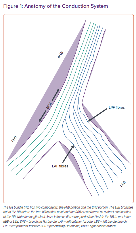
The electrical impulse of the heart arises from the sinus node at the superior vena cava–right atrial junction and reaches the atrioventricular (AV) node via three internodal pathways. The AV node at the apex of Koch’s triangle continues as the HB overlying the membranous septum.7 The membranous septum is divided by the septal tricuspid leaflet into an atrioventricular component and a ventriculoventricular component. The penetrating portion of the HB arises from the anterior end of the AV node with loosely arranged fibres in an interweaving pattern. It reaches the ventricle by penetrating the central fibrous body of the heart, where the fibres of left bundle branch (LBB) are given off after it emerges from the fibrous body at the level of the non-coronary aortic cusp. The branching portion of the HB starts from the point where the posterior-most fibres of the LBB arise (posterior fascicles), to the point where the HB continues as the right bundle branch (RBB) after giving rise to the anterior fascicles of the LBB (Figure 1). The LBB, after its origin, runs inferiorly and anteriorly for 10–15 mm, reaching its maximum width before dividing into anterior and posterior fascicles that head towards the corresponding papillary muscles of the LV.8
Anatomical studies have shown three common variations of HB relative to the ventricular aspect of the membranous septum.9 In the Type I variation (47%), the HB courses along the inferior border of the membranous septum with a thin layer of myocardial fibres spanning from the muscular septum. In the Type II variation (32%), the HB is separate to below the membranous septum and courses within the interventricular muscle. In the Type III variation (21%), the HB is exposed superficially, lying immediately below the endocardium (naked HB). Both atrial and ventricular components of the HB can be accessed for permanent HBP.
His Bundle Pacing: Implantation Technique
Deshmukh et al. first demonstrated the clinical feasibility of HBP in patients with AF and LV dysfunction using standard pacing leads by reshaping the stylet.6 The lead placement was done by targeting the site with largest His deflection recorded from the electrophysiology mapping catheter. This technique was fraught with high pacing thresholds and frequent lead dislodgements. The development of specialised sheaths (C304, C315His and C304His, Selectsite; Medtronic) and a pacing lead (3830 Selectsecure; Medtronic) has made HBP technically feasible with high implant success rates.10
HBP is performed using continuous recording of intracardiac electrograms and 12-lead ECG in an electrophysiology (EP) recording system.10 His signals are recorded directly from the pacing lead tip in a unipolar connection, and are simultaneously recorded in the EP system and in the pacing system analyser (PSA). After obtaining venous access, the C315 sheath is introduced over the guidewire and placed across the tricuspid valve. The sheath has a proximal curve to point towards the tricuspid annulus and a septal curve to direct the lead towards the His region. A 3830 Selectsecure lead is then advanced just exposing the helix outside the sheath, and the His signals mapped in unipolar fashion. Both the atrial and ventricular parts of the membranous septum can be targeted for HBP. If a predominant atrial signal is recorded, the sheath is moved gently forward with clockwise rotation aiming for a larger His signal with a small or no atrial component.
Gu et al. showed that visualisation of the tricuspid valve annulus by performing contrast angiography before lead implantation resulted in a shorter fluoroscopic time (7.1 versus 10.1 minutes) with similar capture thresholds.11 There was no significant difference in procedural success rates. Zanon et al. demonstrated that HBP can be performed primarily using an electrogram with zero or minimal fluoroscopy with high success rates.12 In that study, the sheath, along with the lead, was advanced gently with counterclockwise and clockwise rotation into the right atrium through a standard 7 Fr introducer. The pacing lead was then connected to the alligator cable in a unipolar fashion. After confirming the position of the sheath in the atrium by a sharp atrial signal in the recording system, the system was advanced gently to get both atrial and ventricular signals. Further anticlockwise rotation helped reach the HB area.12 Gentle manipulation of the system helped record a clear near-field His potential from the pacing lead. Unipolar threshold measurement was performed at a pulse width of 1 ms before fixing the lead in the membranous septum. Transient fluoroscopy was used in all patients to confirm lead stability before removing the C315 sheath. Both selective and non-selective HB capture was accepted as procedural success. HBP could be performed safely in 95% of patients (39/41) in that study using electrograms with minimal or zero fluoroscopy.12
Alternatively, HBP can be performed using 3D electroanatomical mapping (EAM), especially in patients with complex heart disease.13 Sharma et al. created EAM of the RA before lead placement using a conventional 3D mapping system.13 His bundle potentials were tagged. The approach to mapping was axillary or cephalic unless the patient was undergoing an AV junction ablation, in which case a femoral approach was used. Pacing was done at the sites with His potentials to note the response to pacing. The 3830 lead was implanted using a C315 or C304 sheath with continuous tracking of the lead course using the 3D system. Transient fluoroscopy was used to confirm full helix deployment and lead slack. Sharma et al. concluded that EAM-guided HBP could significantly reduce fluoroscopy duration and exposure.13
Once a sharp near-field His signal is identified, unipolar pacing is done to confirm the capture of the HB. Intracardiac electrograms and 12-lead ECG will help assess conduction system capture. In patients with underlying bundle branch block or His–ventricle (HV) block, mapping of the distal HB must be done to achieve complete correction of bundle branch block or to overcome HV block. If an optimal site is identified, the fluoroscopic image may be saved as a reference in orthogonal oblique views (left anterior oblique [LAO] 30° and right anterior oblique [RAO] 30°). The sheath is held firmly with a gentle counterclockwise torque to oppose it towards the septum and five to six clockwise rotations are given to the pacing lead without releasing it between rotations. Lead rotations can be best visualised in the LAO 30° fluoroscopic view. Rebound of the lead after the rotation will confirm its penetration into the membranous septum. If lead rebound is not observed, the sheath position is optimised to provide adequate support before giving further rotations. Care must be taken to avoid pinning the tricuspid leaflet into the septum when the ventricular component is targeted by using contrast angiography or echocardiography if there is difficulty in deploying the lead. Alternatively, the sheath can be moved into the RV apex and pulled back gradually to the target site.
After confirming lead fixation, the sheath is gently withdrawn into the high right atrium, providing adequate slack for the lead. The lead parameters are checked in both the unipolar and bipolar configuration. Optimal parameters include a unipolar pacing threshold of <1.5 V at a pulse width of 1 ms and a sensed R-wave of >1.5–2 mV without atrial oversensing. An HB current of injury (COI) recorded from the pacing lead electrogram indicates lead fixation in the HB and predicts excellent pacing thresholds.
Defining Selective and Non-selective Capture of the His Bundle
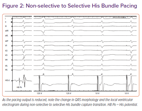
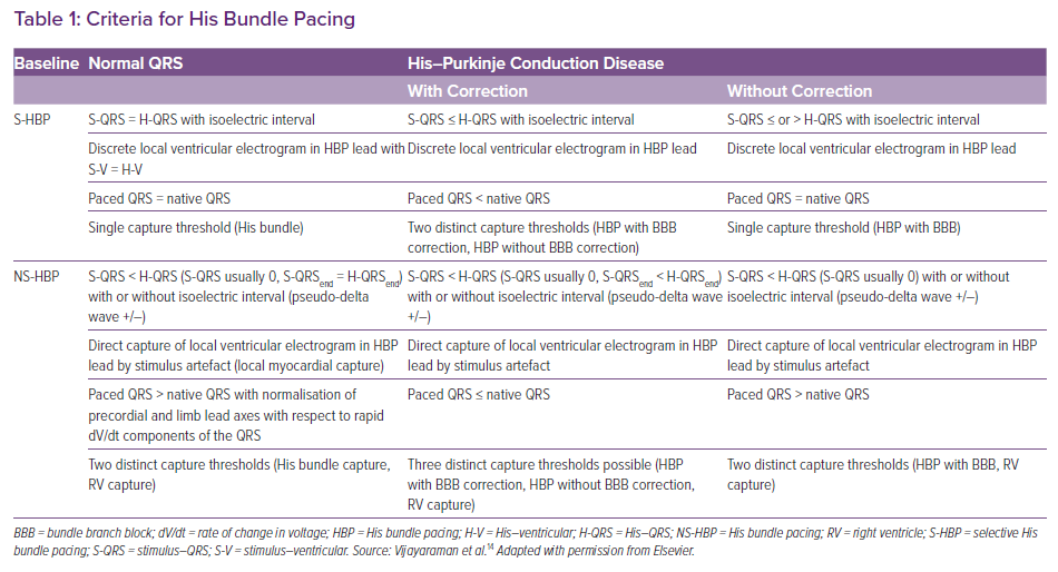
Based on the paced QRS morphology, two forms of HB capture can be observed: selective (S) and non-selective (NS) HBP.14 During selective capture, pacing will result in direct activation of the HB alone and the ventricular activation occurs completely through the His–Purkinje system (HPS). Because the impulse takes 35–55 ms to reach the ventricular myocardium, there will be an isoelectric interval before the onset of QRS, and the interval from the pacing spike to the onset of QRS (S-QRS) will be equal to the native HV interval. However, in patients with significant HPS disease, the S-QRS would be less than the native HV interval. The lead electrogram will show the ventricular electrogram discrete from the pacing artefact, and the paced QRS morphology is same as the native QRS.
During NS-HBP, there will be simultaneous activation of both the HB and the surrounding myocardium (Figure 2). Because ventricular activation starts simultaneously with the pacing artefact due to local myocardial capture, NS-HB capture is characterised by an absent isoelectric interval and slurred QRS upstroke (pseudo-delta wave) and the absence of a discrete local electrogram. The paced QRS duration will be longer than the native QRS duration. There will be two distinct capture thresholds: RV and His capture. In patients with HPS disease, three distinct thresholds may be observed: RV, His capture with correction of bundle branch block and His capture without correction. Various characteristics of S- and NS-HBP in normal and diseased HPS are presented in Table 1. Although S-HBP results in ideal QRS morphology, studies using myocardial perfusion imaging have shown preserved LV electromechanical synchrony even in patients with NS-HBP.15,16 In patients with HV block, NS-HBP provides the advantage of myocardial safety pacing. A recent observational study showed no significant difference in clinical outcomes between S- and NS-HBP.17
Clinical Implications of His Bundle Pacing
HBP is considered as an effective alternative to RVA pacing because it avoids many of the limitations of RVA. HBP can be considered in any patient with symptomatic bradycardia requiring ventricular pacing. Vijayaraman et al. reported an 84% success rate in 100 consecutive patients with AV block.18 The procedural success was higher in patients with AV nodal block (93%) than in patients with infranodal block (76%).18 The three proposed mechanisms for the correction of infranodal block are pacing the HB distal to the site of block, a virtual electrode polarisation effect and a differential source–sink relationship. The role of the HBP as an alternative to biventricular pacing for cardiac resynchronisation therapy (CRT) has been explored with good success.
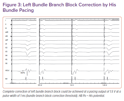
In a retrospective study, Sharma et al. reported 90% procedural success for HBP in 106 CRT-eligible patients.19 On-treatment comparison analysis of the His-Sync Pilot trial showed that patients receiving His CRT had superior electrical resynchronisation and a non-significantly higher echocardiographic response than those receiving biventricular CRT.20 In patients with dilated cardiomyopathy and left bundle branch block (LBBB), Huang et al. achieved a 76% success rate for permanent HBP to achieve CRT and demonstrated very high rates (>85%) of echocardiographic super-response (Figure 3).21
Vijayaraman et al. reported a 95% success rate for HBP in patients with AF and uncontrolled ventricular rates undergoing AV node ablation.22 LV ejection fraction improved from 43% to 50%, with a significant improvement in functional class.22 In another study of 94 patients undergoing AV node ablation, HBP was successful in 86% of patients with an improvement in LV ejection fraction (from 44.9 ± 14.9% [mean ± standard deviation] at baseline to 57.6 ± 12.5% after a median follow-up of 3.0 years).23 The efficacy of HBP may be uncertain in patients with intraventricular conduction delay, significant LV scar and in 10–30% of LBBB patients in whom the site of block may be distal to the HB.
Limitations of His Bundle Pacing
Although considered an acceptable alternative to RV pacing, HBP has some inherent limitations. Because the fibres are electrically insulated from the surrounding myocardium in the membranous septum, the capture threshold for HBP can be higher than that of RV pacing in 10–20% of patients. In our experience, HBP can be successfully achieved in >95% of patients with normal His–Purkinje conduction. In patients with a deeply seated HB, the helix may not be long enough to provide an acceptable pacing threshold. A capture threshold of >2 V at a pulse width of 1 ms may be seen in approximately 10% of patients and, before the advent of left bundle pacing, these values were accepted if NS-HB capture could be demonstrated with a significantly lower RV capture threshold. Approximately 12% of patients were noted to have an increase in pacing threshold of >1 V in our cohort of patients followed up for 5 years.24 Lead revisions may be required during follow-up for an unacceptable increase in threshold in 5–7% of patients.10 During the early phase of the learning curve, RV back-up pacing with an additional lead can be considered. However, if the unipolar pacing threshold is <1.5 V at a pulse width of 1 ms with COI at the time of implantation, back-up pacing may not be required. Other limitations include atrial oversensing, ventricular undersensing, premature battery depletion due to high output pacing and an inability to correct distal conduction system disease.
Left Bundle Branch Pacing
In an attempt to overcome the limitations of HBP, distal conduction system capture was first demonstrated by Huang et al. by deep septal placement of the lead.25 LBBP is defined as the capture of either the proximal left bundle or one of its fascicles along with the septal myocardium at a low threshold.26,27 Anatomically, the left bundle branch is a wide target, with fibres fanning on the left subendocardial aspect of the proximal interventricular septum, compared with the narrow band of the HB. Criteria for confirming LBB capture have been proposed but not validated in large trials. LBB capture is confirmed by paced QRS morphology of RBB delay pattern (qR or rSR in lead V1) along with any one of the following criteria:26,27
- Demonstration of non-selective to selective capture or non-selective to septal capture transition during threshold testing.
- Abrupt shortening of R-wave peak times (RWPT), as measured in leads V5 or V6 during lead implantation at the mid-septum and subsequent short and constant RWPT at the final site.
- Demonstration of LBB potential.
- Programmed deep septal stimulation from the pacing lead to demonstrate conduction system capture, especially selective capture.27
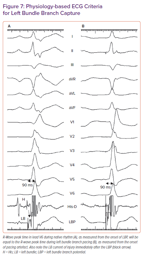
- Meeting physiology-based electrocardiographic criteria, namely paced RWPT in V6 (measured from QRS onset) equals the native RWPT and paced RWPT (measured from the stimulus) equals the LBBP potential to V6.29
Left Bundle Branch Pacing Implantation Techniques
The LBBP implantation tools are the same as those for HBP. Pre-implantation echocardiography should be performed to assess the thickness of the interventricular septum in multiple views, the presence of septal scar, dilatation of cardiac chambers and valvular regurgitation. Careful assessment of the proximal septum is important because it determines procedural success.
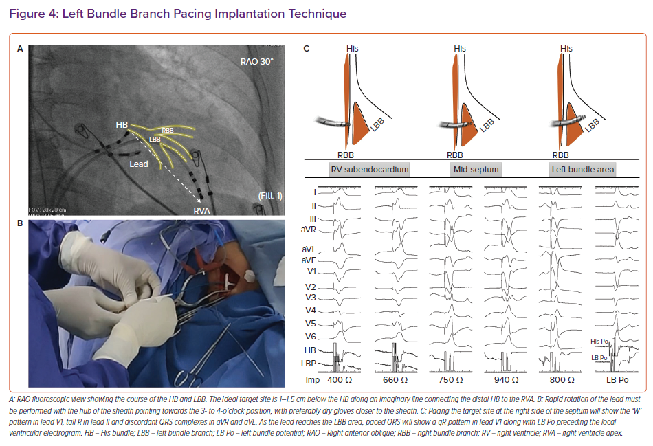
Intracardiac electrograms and 12-lead ECG are continuously recorded using an EP recording system. Placing a quadripolar mapping catheter across the HB is optional to delineate the distal extent of His electrograms. Alternatively, the pacing lead can be used to map the HB to mark its distal extent. After obtaining venous access, the C315 sheath, along with the 3830 lead (Figure 4), is placed in the proximal interventricular septum 1–1.5 cm below the distal HB along an imaginary line connecting the distal HB to the RVA in the RAO 30° fluoroscopic view. Pace mapping of the septum is done by gentle counterclockwise rotation of the sheath to obtain a paced QRS morphology of a ‘W’ pattern in lead V1 with the notch on the nadir of QRS, tall R in lead II, RS in lead III and discordant QRS complexes in leads aVR and aVL. Although classically described, the W pattern is not mandatory, and, in our experience, this is not seen in 20% of patients. The sheath should be held firmly with counterclockwise torque, with the hub of the sheath pointing towards the right hand of the implanter (3 o’clock to 4 o’clock position) to orient it perpendicular to the septum.
Once the optimal site is identified on the right side of the septum, lead deployment can be done by one of two techniques:
- conventional (gradual deployment with monitoring of paced QRS morphology and unipolar pacing impedance); or
- premature ventricular complex (PVC) guided (rapid deployment with monitoring of PVC morphology).
In the conventional technique, the lead is deployed gradually with a few rapid rotations at a time and monitoring of three important parameters: paced QRS morphology (the notch on the nadir of lead V1 will gradually ascend to form an R wave), unipolar pacing impedance (increases gradually before it drops by 100–200 Ω as the lead reaches the LV subendocardium) and myocardial COI on the lead electrogram.26 A drop in pacing impedance of >200 Ω, unipolar impedance <400 Ω and a reduction in sensed R wave amplitude with loss of COI in the unipolar electrogram may suggest lead perforation into the LV cavity.
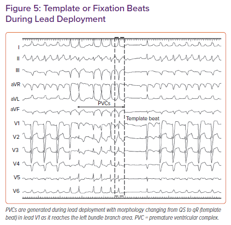
In the PVC-guided lead deployment technique, rapid turns are given to deploy the lead.30 Lead movement during rapid deployment can be appreciated in the LAO 30° view. PVCs are commonly noted during rapid penetration of the lead into the septum (Figure 5). The morphology of PVCs changes from wide QRS with QS morphology in lead V1 to narrow QRS with an RBB delay pattern (qR/rSR) as the lead traverses from the right to left side of the septum. Template or fixation beat is defined as a PVC with an RBB delay pattern and a duration of <130 ms.29–31 Rotations should be stopped immediately on observing a template beat. LBB capture can be confirmed at this site by the aforementioned criteria. Template beat-guided LBBP is associated with less fluoroscopic time and minimal myocardial injury, and avoids septal perforation during lead deployment.29,31
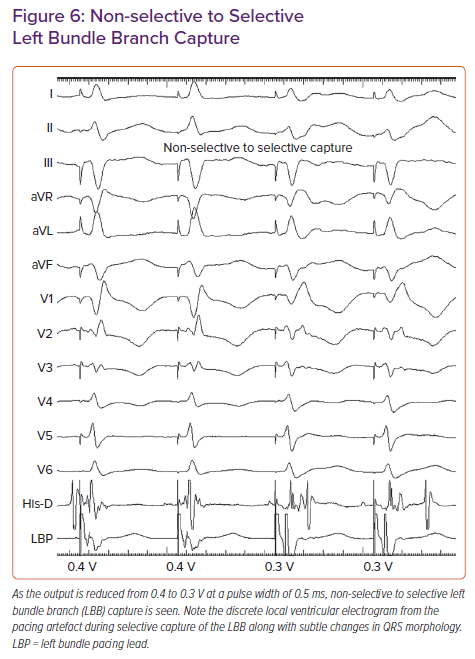
In patients with narrow QRS or RBBB morphology at baseline, a sharp high-frequency LBB potential should be seen preceding the local ventricular electrogram by 20–35 ms. In patients with LBBB, antegrade activation of LBB will not occur due to complete block of conduction in the distal HB/proximal LBB. LBB potential may be demonstrated by His-corrective pacing in patients with LBBB. In some patients the LBB potential may be masked due to significant COI. Concealed LBB potential must be considered before repositioning the lead if other parameters confirm LBB capture.32 Non-selective left bundle (NS-LB) to selective left bundle (S-LB) branch capture transition can be demonstrated during threshold testing at near-threshold output (Figure 6). S-LB capture is characterised by a distinct local ventricular electrogram on the pacing lead separate from the pacing artefact, along with a change in paced QRS morphology. NS-LB is characterised by a pacing artefact immediately followed by a local ventricular electrogram with a pseudo-delta wave on the surface ECG. However, in many patients, demonstration of the isoelectric interval or discrete local electrogram may be difficult due to short stimulus to QRS intervals. RWPT is measured in leads V5 or V6 from the onset of the pacing spike to the peak of the R wave. Differential pacing at 10 and 2 V must produce short and constant RWPT (preferably <80 ms) to confirm the capture of the LBB. If peak LV activation time is prolonged at 2 V compared with pacing at 10 V, additional turns are given to get the shortest RWPT. In patients with cardiomyopathy, LV hypertrophy and distal conduction system disease, RWPT is generally <90 ms, but occasionally may be longer.33
The novel physiology-based ECG criteria for LBB capture proposed by Jastrzebski et al., namely paced RWPT in V6 (measured from QRS onset) equal to native V6 RWPT and paced RWPT (measured from stimulus) equal to the LBB potential to V6 RWPT (Figure 7), had sensitivity and specificity of 98–88% and 85–95% respectively.29 When measured from stimulus, the optimal and 100% specific V6 RWPT values for differentiating LBB capture from LV septal capture in patients with narrow QRS/RBBB were 83 and 74 ms, respectively. In patients with LBBB/ventricular escape rhythm, the optimal and 100% specific values were 101 and 80 ms, respectively.29
After confirming LBB capture, the sheath is gently pulled back into the right atrium with adequate lead slack. There is a tendency for the formation of an alpha loop in the lead while removing the sheath. The alpha loop can be undone in the RAO view by gently retracting the lead back with a counterclockwise rotation. Pacing parameters must be checked again in both the unipolar and bipolar configurations. Because part of the anode is often inside the septum, the anodal capture threshold must be checked by gradually reducing the pacing output in the bipolar configuration. Lead V1 will show changes in QRS morphology from the QS pattern (as the anode captures the right side of the septum) to the qR/rSR pattern once the anode loses it capture. Electroanatomical mapping with creation of 3D geometry of the atrium and ventricle, along with delineation of His signals to facilitate lead deployment, can minimise radiation exposure.34
Troubleshooting Difficult Cases
The reported success rate for LBBP is between 80.5% and 97%.35–37 The reasons for failure include inability of the lead to penetrate deep into the septum, inadequate sheath support and improper sheath–septal orientation. Both the gloves and the lead must be dry while performing rapid rotations. If the basal septum is scarred, the left posterior fascicle can be targeted by placing the lead in mid-septum posteriorly.38 Entanglement of the septal tricuspid leaflet may prevent deep septal penetration of the lead. To overcome this issue, the sheath is advanced towards the RV apex before bringing it back to the target site. RBB conduction delay created by pacing the LBB can be corrected by optimising the AV delay to allow native fusion, by programming pacing output to allow the anodal capture or by placing additional lead in the RV septum. In patients with cardiomyopathy and a diseased distal conduction system, LBBP may not result in ideal electrical resynchronisation. In these patients, LBBP may be combined with a coronary venous lead to achieve maximum electrical resynchronisation.
Clinical Implications
LBBP has the potential to overcome the limitations of HBP because it provides a low and stable threshold, excellent lead stability and the ability to correct conduction disease in the distal HB/proximal LB. In patients with AV block after transcatheter aortic valve replacement, Vijayaraman et al. reported success rates of 63% and 93% for HBP and LBBP, respectively.39 Huang et al. reported a 97% success rate in patients with non-ischaemic cardiomyopathy and LBBB, with significant improvement in LV function.40
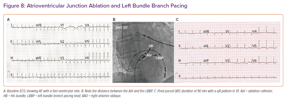
A retrospective multicentre study by Vijayaraman et al. reported an 85% acute procedural success rate for LBBP in 325 CRT-eligible patients.33 LBBP resulted in a reduction in QRS duration from 152 to 137 ms, along with an improvement in LV ejection fraction from 33% to 44%.33 In patients undergoing AV junction ablation, LBBP provides additional safety because the lead is away from the site of ablation compared with HBP (Figure 8).
Limitations of Left Bundle Branch Pacing
Although LBBP provides a low capture threshold, excellent lead stability and a shorter learning curve, long-term safety data are lacking. In a recent report of 632 patients, Su et al. reported a 97.8% success rate for LBBP.41 The mean follow-up time in that study was 18.6 months and the LBBP capture threshold remained stable at the 2-year follow-up. RBB injury was noted in 8.9% of patients and 1% of patients had either loss of capture or an increase in the threshold to >3 V with successful LBBP.41 Lead perforation into the LV cavity, RBB injury, myocardial trauma with troponin release, septal arterial injury and coronary cameral fistula are potential complications to be monitored.42–44 The implications of extraction of an LBBP lead implanted deep in the septum are unknown. Large-scale randomised multicentre studies are required to establish the long-term safety and efficacy of LBBP before it can be adopted as the main pacing strategy.
Conclusion
Conduction system pacing has gained significant interest over the past decade with the development of specially designed tools. HBP and LBBP are acceptable alternatives to RV pacing. The limitations of HBP are well addressed by LBBP, which provides a remarkably low and stable threshold. Early data suggest that HBP and LBBP may also be reasonable alternatives to biventricular pacing to achieve CRT.