


Abstract
In this letter, surface effects on the vibration and buckling of a clamped-clamped piezoelectric nanoplate (PNP) are investigated by using Kirchhoff plate theory with the incorporation of the surface piezoelectricity model and the generalized Young-Laplace equations. Ritz solutions show that the surface effects on the resonant frequency are more prominent for the PNPs with smaller thickness and larger aspect ratio, with dominant effect from surface piezoelectricity and residual surface stress. Results also suggest potential for frequency tuning of the PNPs via applied electric potentials. Simulation results on the critical buckling potential indicate that the influence of the combined surface effects is the competition between the residual surface stress and surface piezoelectricity. This work is helpful for the characterization of the mechanical properties and design of PNP-based devices.
Export citation and abstract BibTeX RIS
Introduction
The enhanced piezoelectricity and unique coupling between piezoelectric and semiconducting properties of piezoelectric nanomaterials make them attractive for applications as sensors, resonators, generators and transistors in the nanoelectromechanical systems (NEMS) [1–6]. To better understand the underlying mechanisms and improve the performances of these advanced devices, some fundamental issues must be clearly addressed, for example, the vibration and buckling behaviors of piezoelectric nanostructures.
Different from their macroscpoic counterparts, nanomaterials exhibit size-dependent mechanical and physical properties due to their large surface area to volume ratio. For example, experimental investigations and atomistic simulations have demonstrated that the elastic constants or the piezoelectric coefficients of some piezoelectric nanomaterials increase dramatically with the decrease of the material size to the nanoscale [7–10]. In the literature, modified continuum mechanics theories have also been adopted as alternative and cost-effective tools to study the surface effects on the size-dependent properties of elastic nanostructures with various configurations [11–15] based on the surface elasticity model developed by Gurtin and Murdoch [16]. However, this surface elasticity model is not sufficient in predicting the size-dependent properties of piezoelectric nanomaterials since it neglects surface piezoelectricity effect, which is unique for piezoelectric materials. As pointed out by Tagantsev [17], the effect of surface piezoelectricity may become significant with the miniaturization of piezoelectric materials into a nanoscale size. Therefore, it is essential to incorporating the effect of the surface piezoelectricity to investigate the electroelastic properties of piezoelectric nanomaterials. As an extension of the surface elasticity model, a surface piezoelectricity model with the consideration of the surface piezoelectricity as well as the residual surface stress and surface elasticity, was first proposed by Huang and Yu [18] to study the electroelastic responses of a piezoelectric nanoring. Based on this model, the surface effects on the bending, vibration and buckling behaviors of piezoelectric nanobeams have been recently investigated in our previous work [19, 20]. It is found that the influence of the surface piezoelectricity on the static and dynamic behaviors of the piezoelectric nanobeams is significant. Li et al. [21] studied the surface effects on the wrinkling of a piezoelectric nanofilm on a compliant substrate. Their results showed that the wavelength and amplitude of the wrinkling were significantly affected by the surface parameters for the films with nanoscale thickness. However, the investigation of the surface effects on two-dimensional piezoelectric nanostructures is very limited. In order to enrich the studies on the plate-like piezoelectric nanostructures, the present work aims to develop a modified piezoelectric plate model based on the classical Kirchhoff plate theory and the surface piezoelectricity model to study the surface effects on the vibration and buckling behaviors of a piezoelectric nanoplate (PNP). Simulation results will show how the influence of the surface effects on the resonant frequency and the critical buckling potential changes with the PNP thickness and aspect ratio. In addition, the possibility of frequency tuning via applied electric potentials will also be investigated.
Modified plate model and formulation
The problem considered is a rectangular PNP with thickness h, in-plane length a and width b, as illustrated in fig. 1. A Cartesian coordinate (x1, x2, x3) is used to describe the plate with x1 and x2 axes and the origin at the mid-plane of the undeformed plate, and x3-axis in the thickness direction. The PNP is poled along the x3-direction and is subjected to an electric voltage V . Following Kirchhoff's hypotheses, the displacements at any point of the plate are expressed as
where u0α are the in-plane displacements of the mid-plane and w is the transvere displacement. Such mid-plane displacements describing the membrane deformations may be induced by the in-plane applied mechanical load, the applied electrical load due to the electromechanical coupling or the residual surface stress induced relaxation [22, 23]. The usual convention of summation over repeated indices is used here, e.g., Greek indices run from 1 to 2. Accordingly, the in-plane strains for the Kirchhoff plate can be written as
The electric field E is assumed to exist only along the x3-direction and can be expressed in terms of the electric potential Φ as
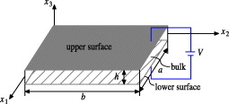
Fig. 1: Schematic plot of a PNP with upper and lower surfaces.
Download figure:
Standard imageFollowing the surface piezoelectricity model, the plate itself is composed of a bulk part and the upper and lower surface layers with negligible thickness. The constitutive equations for the surface layers of the PNP are different from the bulk, which are given as
where σsαβ and Dsγ are surface stresses and surface electric displacements; csαβγδ, es3αβ and κsγδ are elastic, piezoelectric and dielectric constants for the surfaces; σ0αβ and D0γ are residual surface stresses and residual surface electric displacements. Following the assumption [24] that the stress component in the x3-direction is negligible, the in-plane stresses σαβ and electric displacement D3 for the bulk are expressed as

with cαβγδ, e3αβ and κ33 being the bulk elastic, piezoelectric and dielectric constants for the plane stress problem.
According to the generalized Young-Laplace equations, the existence of surface can be represented by the traction jumps Ti exerting on the bulk of the plate, which can be expressed in terms of the surface stresses as

The superscripts u and l denote the upper and lower surfaces of the plate, respectively. It should be noted that the electric displacement jump across the surfaces is zero.
In the absence of free electric charges, the electric displacement should satisfy the Gauss's law
Applying the electric boundary conditions Φ(h/2) = V and Φ(−h/2) = 0, the electric potential and the electric field distribution can be determined.
For the transverse vibration of the PNP, the motion equation is derived as

where ρ is the mass density, N*αβ, M*αβ are the generalized resultant forces and moments for the PNP with the consideration of surface effects, i.e.,
with Nαβ and Mαβ being the axial forces and bending moments in the bulk of the plate defined as

It should be noted that the subscripts in the material constants as shown in eqs. (4) and (5) can be relabeled in the contracted notation due to the symmetry of stress and strain tensors following  . In the following formulation and discussion, the material constants in the contracted notation, i.e., c11,c12,c66,cs11,cs12,cs66,e31 and es31 will be used. After the manipulation of the equations above, the transverse motion equation of the PNP with surface effects can be derived in terms of w(x1,x2,t) as
with
Obviously, the in-plane constraints for the PNP must be prescribed first to solve eq. (11). For a clamped-clamped plate with four edges being fully restrained, it is reasonable to set the displacements u0α(x1,x2) as zero, which was adopted by Zhao et al. [24] for a conventional piezoelectric plate. Moreover, the residual surface stress are assumed as σ011 = σ022 = σ0 and σ012 = 0. The harmonic solution of eq. (11) takes

where ω is the resonant frequency and W(x1,x2) represents the vibration mode. Substituting eq. (13) into eq. (11) results in
with  being the biaxial force induced by the applied electrical load and residual surface stress. Such a force may cause the buckling of PNPs.
In order to do the vibration and buckling analysis, the Ritz method [25] is adopted to get the approximate solutions. The weak form of the variational statement of eq. (14) is written as
According to the Ritz method, the transverse deflection of the PNP can be approximated by
where cij are the unknown constants, and Xi(x1) and Yj(x2) are the coordinate functions satisfying the boundary conditions. For the clamped-clamped PNP, W should satisfy W = 0 and ∂W/∂x1 = 0 at x1 = 0 and x1 = a; W = 0 and ∂W/∂x2 = 0 at x2 = 0 and x2 = b. Accordingly, Xi(x1) and Yj(x2) are chosen as [25]
Substituting eq. (16) into eq. (15), we have

with
and
Then, the resonant frequency ω of the PNP can be obtained by solving the characteristic equations of (18).
Due to the inherent electromechanical coupling of piezoelectric materials, the applied electrical load generates in-plane forces when the in-plane displacements of the plate are constrained, which may cause the mechanical buckling of the PNP once the resulting forces become compressive. Moreover, the surface stresses may also contribute to these in-plane forces, as shown in eq. (9). Therefore, it will be interesting to investigate the buckling behavior of the PNP with surface effects. The equation governing the buckling behaviors of PNPs can be determined by letting ω = 0 in eq. (14). Similarly, substituting eq. (16) into eq. (15) with ω = 0 results in

with
and
After determining f from the characteristic solutions of (21), the critical electric potential for buckling is calculated as
Results and discussion
To quantitatively show the surface effects on the vibration and buckling behaviors of the PNP, PZT-5H is chosen as an example material for case study. Its macroscopic material constants are taken as c11 = 102 GPa, c12 = 31 GPa, e31 = −17.05 C/m2 and κ33 = 1.76 × 10⁻⁸ C/Vm. Since the surface material constants are not completely available due to the lack of atomic calculations and experiments, the values adopted in [18] are used in the current work, i.e., cs11 = 7.56 N/m, es31 = −3.0 × 10⁻⁸ C/m. In addition, the other surface material constants are taken as σ0 = 1.0 N/m, cs12 = 3.3 N/m and cs66 = 2.13 N/m.
For a PNP (a = b = 20h) subjected to V = − 0.1 V, fig. 2 shows the normalized first mode resonant frequency vs. the plate thickness, where ωV is the resonant frequency of the PNP without the surface effects. With the considered values of the surface material constants, it is found that the separate influence of the surface piezoelectricity is obvious the largest in comparison with the residual surface stress and the surface elasticity for the PNP with small thickness, for example, h < 30 nm. This observation indicates the importance of applying the surface piezoelectricity model to investigate the mechanical property of piezoelectric nanostructures. With the increase of the plate thickness h, the influence of the surface effects diminishes and this normalized resonant frequency tends to approach 1. As reported in [13], the residual surface stress may vary from a negative value to a positive one. The combined surface effects with setting σ0 = 0 N/m and σ0 = −1.0 N/m are also provided in this figure for comparison with σ0 = 1.0 N/m. The obvious discrepancy among these curves indicates that this surface piezoelectricity model is sensitive to the values of surface material constants. Figure 3 plots the normalized resonant frequency vs. the plate thickness for the PNP with different in-plane aspect ratio, b/a = 0.25, 0.5 and 1.0 for example. It is observed that the influence of the surface effects on the normalized resonant frequency increases as b/a increases for a given a/h. When the in-plane aspect ratio b/a is fixed, the influence of the surface effects also increases with the aspect ratio a/h. These results indicate that the surface effects are more prominent for PNPs with smaller thickness and larger in-plane area.
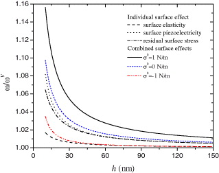
Fig. 2: (Colour on-line) Variation of normalized resonant frequency with plate thickness (a = b = 20h, V = − 0.1 V).
Download figure:
Standard image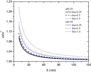
Fig. 3: (Colour on-line) Normalized resonant frequency vs. plate thickness for different plate aspect ratios (V = − 0.1 V).
Download figure:
Standard imageFigure 4 depicts the variation of ω/ω0 vs. h with ω0 being calculated without considering the surface effects and the applied electric potential. It is seen that the influence of the surface effects is significantly affected by the applied electrical load, which is similar to that observed for a simply supported piezoelectric nanobeam [20]. The variation of the resonant frequency with the applied electrical load suggests possible frequency tuning of PNPs by the applied electric potentials. Such frequency tuning concept is expected to provide guidelines for the design and applications of PNPs as resonators. It is interesting to note that with the increase of the electric potential or the decrease of the plate thickness, the resonant frequency may drop down. This phenomenon indicates a possible mechanical buckling of the PNP caused by the combined electrical load and the surface effects, which is an important issue needs to be addressed in order to keep the mechanical integrity of the structures.
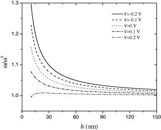
Fig. 4: Normalized resonant frequency vs. plate thickness for different applied electric potentials (a = b = 20h).
Download figure:
Standard imageFigure 5 shows the normalized critical electric potential Vcr/V0cr for buckling (V0cr is calculated without surface effects) vs. the plate thickness h. Similar to the trend observed in fig. 2, the surface effects on Vcr/V0cr are more prominent for smaller h. Although the combined surface effects are not significant, the separate influence of the surface piezoelectricity and the residual surface stress is obvious when h is small, for example, h < 30 nm. It is the competition between these two surface effects that ends up with a smaller combined effect. Again this result suggests the importance of incorporating the surface piezoelectricity into the plate model to study the mechanical behavior of the PNP, otherwise may lead some misleading predictions. The influence of the surface effects on the critical electric potential of the PNP with different aspect ratios is displayed in fig. 6. It is found that the influence of the surface effects is significantly affected by the aspect ratio. When a/h = 20, the surface effects decrease the critical electric potential of the PNP for b/a = 0.25, 0.5 and 1.0. However, such a trend is changed for a PNP with larger surface area, a/h = 30 and b/a = 1.0 for example. This phenomenon could be explained by studying the individual surface effect as presented in fig. 7. Since the influence of the surface elasticity is much smaller than that of the residual surface stress and surface piezoelectricity, we just ignore the surface elasticity here. From fig. 7, it is found that the residual surface stress always increases the critical electric potential, and such effect is further enhanced with the increase of the in-plane aspect ratio b/a. However, the surface piezoelectricity always decreases the critical electric potential and its influence is independent of the aspect ratio b/a. Therefore, the residual surface stress becomes dominant with the increase of b/a and a/h, resulting the trend change for the combined surface effects on the critical electric potential observed in fig. 6.
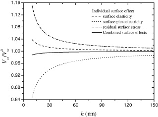
Fig. 5: Variation of normalized critical electric potential for buckling with plate thickness (a = b = 20h).
Download figure:
Standard image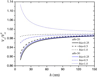
Fig. 6: (Colour on-line) Normalized critical electric potential vs. plate thickness for different plate aspect ratios.
Download figure:
Standard image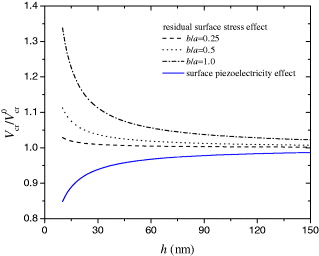
Fig. 7: (Colour on-line) Normalized critical electric potential vs. plate thickness considering residual surface stress and surface piezoelectricity separately (a/h = 30).
Download figure:
Standard imageConclusions
In summary, a modified plate model is developed based on the classical Kirchhoff plate theory and the surface piezoelectricity model to investigate the surface effects on the vibration and buckling of the PNPs. Simulation results show that the surface piezoelectricity has a significant effect on the resonant frequency and critical electric potential for buckling, indicating the importance of using the surface piezoelectricity model in predicting the mechanical behavior of the PNPs. The surface effects on the resonant frequency of the PNPs are found more prominent for the PNPs with smaller thickness and larger in-plane aspect ratio, while the influence of the surface piezoelectricity on the critical electric potential for buckling is independent of such aspect ratio. This study also suggests the possible frequency tuning of PNPs via applied electric potentials. The fundamental investigations on the mechanical behavior of PNPs carried out in this work might be helpful for the design and applications of PNP-based nanodevices.
Acknowledgments
This work was supported by Natural Sciences and Engineering Research Council of Canada (NSERC) and Academic Development Fund of UWO.