Abstract
We synthesized Pt and PtRu catalysts supported on Ta-doped SnO2 (Pt/Ta-SnO2, PtRu/Ta-SnO2) for the anodes of direct oxidation fuel cells fueled with poly-oxymethylene-dimethylether (POMMn, n = 3∼8). The onset potential for the oxidation of the hydrolyzed fuel of POMM3 (h-POMM3; methanol-formaldehyde mixtures with the composition equivalent to 100% hydrolyzed POMM3) on Pt/Ta-SnO2 and PtRu/Ta-SnO2 was at least 0.2 V lower than that on a commercial Pt2Ru3/carbon black (c-Pt2Ru3/CB). The Pt-based mass activities at 0.50 V (MA0.50V) of PtRu/Ta-SnO2 for the h-POMM3 and formaldehyde oxidations were more than four times larger than those of the c-Pt2Ru3/CB. Elemental tin was found to exist on the top surface, brought by the diffusion from the Ta-SnO2 support. The elemental tin may contribute to enhancing the anodic reaction via an acceleration of carbon monoxide oxidation by a bifunctional mechanism or ligand effect. Single cells using Pt/Ta-SnO2 and PtRu/Ta-SnO2 as anodes exhibited higher current densities in all voltage regions when supplied with the h-POMM3 fuels dissolved in water. We deduced that both the elemental tin diffusion from the Ta-SnO2 support to the catalyst nanoparticles and the unique fused-aggregate network structure of the Ta-SnO2 support contribute to enhancing the performance of POMMn-based fuel cells.
Export citation and abstract BibTeX RIS

This is an open access article distributed under the terms of the Creative Commons Attribution 4.0 License (CC BY, http://creativecommons.org/licenses/by/4.0/), which permits unrestricted reuse of the work in any medium, provided the original work is properly cited.
Polymer electrolyte fuel cells (PEFCs) supplied directly with liquid fuels are suitable as power sources for various portable applications with extended operating time. Liquid alcohol fuels such as methanol and ethanol are attractive energy carriers with environmental compatibility, good energy density and low cost.1–6
The liquid oligomers of poly-oxymethylene-dimethylethers (POMMn: CH3-O-(CH2-O)n-CH3, n = 3∼8) have also been proposed as an alternative class of liquid fuels for the future,7 but they have several hurdles to clear before they can enjoy widespread use. Fortunately, the POMMn preparation from methane has already been established as an industrial process, with the methane feedstock existing on a massive scale as natural gas and even as a by-product from oil wells.8 The POMMn compounds have been applied as raw materials of the polyacetal resins used in vehicle parts and medical devices.8–10 A project on the application of POMMn has been conducted in Germany.8 The POMMn compounds have no corrosive properties for steels used containers of various sizes, including tankers. Other attractive properties are non-toxicity, high flash points (>64°C) and high boiling temperatures (ca. 100°C), unlike methanol. In addition, the POMMn compounds can easily and immediately hydrolyze under acidic conditions to form methanol and formaldehyde (Eq. 1):7,11–13
![Equation ([1])](https://content.cld.iop.org/journals/1945-7111/164/12/F1226/revision1/d0001.gif)
Thus, the POMMn class of compounds is becoming one of the more promising candidates for new energy carriers for use in fuel cells, and the essential properties described above have the potential to lower the hurdle of cost, to improve the safety, and to maintain a stable supply, in comparison with other energy carriers such as methanol, even with increasing demand for POMMn fuels in the market.
The oxidation of both methanol and formaldehyde produces carbon monoxide as an intermediate, which leads to poisoning of the platinum surface and reduction of the anodic activity. Pt alloys such as PtRu and PtSn can exhibit enhanced CO tolerance based on the bifunctional mechanism and ligand effects.14–27 Recently, our group developed a colloid-deposition method for Pt and PtRu catalysts supported on Nb-doped SnO2 particles with a fused-aggregate network structure. These catalyst particles contained elemental tin, which diffused from the Nb-doped SnO2 support during the sintering process. We found that the catalyst exhibited higher anodic activity in 0.1 mol dm−3 HClO4 solution fueled directly with the hydrolyzed fuel of POMMn (h-POMMn; methanol-formaldehyde mixtures with the composition equivalent to 100% hydrolyzed POMMn (n = 2–8), in comparison with that of a c-Pt2Ru3 catalyst supported on carbon black (Pt/CB).13 We also succeeded recently in the synthesis of a Ta-SnO2 support with a fused-aggregate network structure.28 The support has much higher electrical conductivity than that of the previous Nb-SnO2 support and is expected to have improved anodic activity and cell performance.
In this paper, we report the synthesis of Pt and PtRu catalysts supported on Ta-SnO2 (Pt/Ta-SnO2, PtRu/Ta-SnO2) with the fused-aggregate network structure by the new colloidal method and their superior anodic reaction activities for the oxidation of h-POMM3. The latter were evaluated in half-cells with a rotating electrode (RDE) at various temperatures from ambient to 80°C and also in single cells at 80°C, and the anodic reaction activities for the oxidation of h-POMM3, methanol and formaldehyde were compared to those for a highly optimized commercial Pt2Ru3/CB. In the present work, catalysts with the 1:1 Pt-Ru composition ratio were chosen, based on our previous work.29 It should be noted that, since the elemental ratios differ, a strict comparison cannot be made, so the Pt2Ru3/CB catalyst should be considered as a reference, although the variation is expected to be less than ca. 10% (see Supporting Information for detailed discussion).
Experimental
Electrochemical measurements
Electrochemically active surface areas of each catalyst were estimated conventionally by the CO stripping method. Each catalyst was maintained at 0.05 V for 30 min. in 0.1 mol dm−3 HClO4 solution saturated with CO by bubbling mixed gas (1% CO + 99% N2) to ensure that the Pt sites were sufficiently covered by CO. Then, the CO stripping charge was measured in N2-saturated 0.1 mol dm−3 HClO4 solution (CO-free condition) at 10 mV s−1 to oxidize the adsorbed CO (COads) on the working electrode. The h-POMMn (n = 3∼8) fuels are oxidized much more quickly than the original, unhydrolyzed ones.8,9 Based on these previous works, a simulated fuel mixture of methanol and formaldehyde was used as a convenient model for the 100% hydrolyzed fuel of 0.25 mol dm−3 POMM3 (mixture of methanol and formaldehyde, 0.5 and 0.75 mol dm−3, respectively, dissolved in 0.1 mol dm−3 HClO4 solution), which is equivalent to either 1 mol dm−3 methanol alone or 1.5 mol dm−3 formaldehyde alone in the amount of electric charge (6 equivalents) for complete oxidation. The electrochemical activities of Pt/Ta-SnO2, PtRu/Ta-SnO2 and c-Pt2Ru3/CB for the oxidation of h-POMM3 fuel, as well as the pure formaldehyde and methanol solutions, were evaluated from hydrodynamic voltammograms at various temperatures in the 0.1 mol dm−3 HClO4 electrolyte solutions by use of the half cell. We calculated the Pt based mass activity of these catalysts for those fuels based on the activities. Various catalysts mentioned above were uniformly dispersed on each working disk electrode (5 mm in diameter) at a constant loading of platinum, 11 μg cm−2. Nafion films were cast on the catalyst layer (CL) with an average film thickness of 0.1 μm. A platinum mesh was used as the counter electrode. The electrolyte solution of 0.1 mol dm−3 HClO4 was prepared from reagent grade chemicals (Kanto Chemical Co.) and Milli-Q water (Milli-Pore Japan Co., Ltd.) and purified in advance by conventional pre-electrolysis methods. The electrolyte solution was saturated with N2 or O2 gas bubbling for at least 1 h prior to the electrochemical measurements. All electrode potentials were controlled by a potentiostat (HZ-5000, Hokuto Denko Co.) with respect to a reversible hydrogen electrode (RHE).
Preparation of catalysts
The Ta-SnO2 nano-sized particle supports with fused-aggregate network structure were synthesized by the flame oxide synthesis method; details of the method are described in earlier papers.30–33 Briefly, reagent grade 2-ethylhexanoate salts of Sn and Ta (Nihon Kagaku Sangyo, Co. Ltd.) were mixed at desired ratios into turpentine oil. The mixtures were supplied into the burner (>1000°C) of a flame combustion system (FCM-Mini, Hosokawa Micron Co.). The particles obtained were sintered at 800°C for 2 h in air in a rotary kiln furnace (Alfa Engineering, Inc.). The surface area of the Ta-SnO2 support was 35 m2 g−1, estimated by the Brunauer-Emmett-Teller adsorption method (BET, BELSORP-max, MicrotracBEL Co.). The Pt and Ru colloid particles were loaded on the support by a colloidal method.29 Pt/Ta-SnO2 was heat-treated at 800°C in nitrogen for 2 h and then quenched at room temperature. The PtRu/Ta-SnO2 was heat-treated at 400°C in air for 0.5 h, 150°C in 1% H2 (N2 balance) for 1 h, 800°C in nitrogen for 2 h, and then quenched at room temperature. A commercial Pt2Ru3 catalyst supported on carbon black (denoted as c-Pt2Ru3/CB, TEC61E54, mean particle size d = 3.5 nm, Pt 29.7 wt%, Ru 23.0 wt%, Pt:Ru = 2.00:2.99 (atomic ratio), Tanaka Kikinzoku Kogyo K. K.) was used as a reference. The crystalline phases of these catalysts were characterized by X-ray diffraction measurements (XRD, Ultima 4, Rigaku Co.) with Cu Kα radiation (0.15406 nm, 40 kV, 40 mA). Contents of the Pt and PtRu catalysts on the Ta-SnO2 support were quantitatively analyzed by use of an inductively coupled plasma-mass spectrometric analyzer (ICP-MS, 7500CX, Agilent Technologies Inc.). After a pretreatment of these catalysts by the alkaline fusion method (sodium carbonate and sodium peroxide), the analyses were performed with the aqueous hydrochloric acid solutions. The chemical compositions of Pt and Ru were 16.2 wt% (Pt in Pt/Ta-SnO2), 13.0 wt% (Pt in PtRu/Ta-SnO2) and 6.3 wt% (Ru in PtRu/Ta-SnO2, Pt:Ru = 1.00:0.94 (atomic ratio in PtRu/Ta-SnO2)).
The particle size distributions, dispersion conditions and element distributions of the catalysts thus obtained were characterized by images with high-angle annular dark field-scanning transmission electron microscopy (HAADF-STEM) from a scanning transmission electron microscope (STEM, HD-2700, Hitachi High-Technologies Co.) with an energy dispersive X-ray spectroscopic attachment (EDX, Quantax XFlash 5010, Bruker AXS K. K.). The electronic states of Pt and Sn in the Ta-SnO2 supported catalysts were characterized with in-situ X-ray photoelectron spectroscopy (XPS, JPS-9010, JEOL Ltd.) without exposure to the atmosphere after the heat-treatment mentioned above.
Evaluation of single cell performances
Three types of MEAs were fabricated by using Pt/Ta-SnO2, PtRu/Ta-SnO2, and c-Pt2Ru3/CB as the anode catalysts and a commercial Pt/CB (TEC10E50E, Tanaka Kikinzoku Kogyo K. K.) as the cathodes, respectively. The CLs were formed on the polymer electrolyte membrane (Nafion NRE 117, Du Pont Co.) by spraying ink containing each catalyst, which was described in previous papers.29 The Pt loading amounts on anode and cathode were 0.3 mg cm−2 and 0.5 mg cm−2, respectively. The volume ratio of perfluorosulfonic acid binder (PFSA; equivalent weight = 909 g eq−1, Asahi Glass Co., Ltd.) and support in the ink was 0.7 (volume ratio, dry basis). The catalyst-coated membranes obtained (CCMs: electrode area, 29.2 cm2) were heat-treated at 120°C for 30 min. Then, the CCMs were sandwiched with two gas diffusion layers (PX30, ZOLTEK Co.) to form the MEAs. The MEAs were mounted in single cells with carbon plates that included a multi-channel serpentine flow field. The cell voltage (V) as a function of current density (I) was measured by supplying an aqueous solution in which was dissolved h-POMM3 (mixture of methanol and formaldehyde, 2 and 3 mol dm−3, respectively), 2 mol dm−3 methanol or 3 mol dm−3 formaldehyde fuel to the anode at 80°C. The flow rates of each fuel into the anode were controlled at 3 × 10⁻³ dm3 min−1 by a plunger fixed-quantity pump (IP-7100; Lab-Quatec Co.). The oxygen was bubbled through a hot water reservoir so that it was humidified at 100% relative humidity (RH) and was supplied to the cathode (1 atm, 0.30 dm3 min−1). The I-V curves were measured galvanostatically in steady-state operation, with a measurement time of 5 min for each point by use of an electronic load (PLZ-664WA, Kikusui Electronics Co.) controlled by a measurement system (PEMTest 8900, Toyo Co.).
Results and Discussion
Materials characterization of Pt/Ta-SnO2 and PtRu/Ta-SnO2
TEM images of Pt/Ta-SnO2 and PtRu/Ta-SnO2 are shown in Figs. 1a and 1b. Each of the Ta-SnO2 nanoparticles (diameter > 10 nm) were partially fused with nearest neighbors and formed a fused-aggregate network structure. This type of network structure is desirable to form electronically conductive pathways.28,30–33 Such a structure also constructs open pores from 10 nm to 50 nm in diameter, surrounded by fused particles, which should act as mass transport pathways for reactants such as oxygen and the present fuels.28,30–33 The Pt and PtRu particles (diameter < 10 nm) were highly dispersed on the supports, as shown in the TEM images (Figs. 1a and 1b). As shown in Figs. 1c and 1d, Pt/Ta-SnO2 exhibited a broader size-distribution and a larger mean-particle size (d) than PtRu/Ta-SnO2, i.e., d = 6.3 ± 1.0 nm for the former and 4.1 ± 0.6 nm for the latter, respectively.
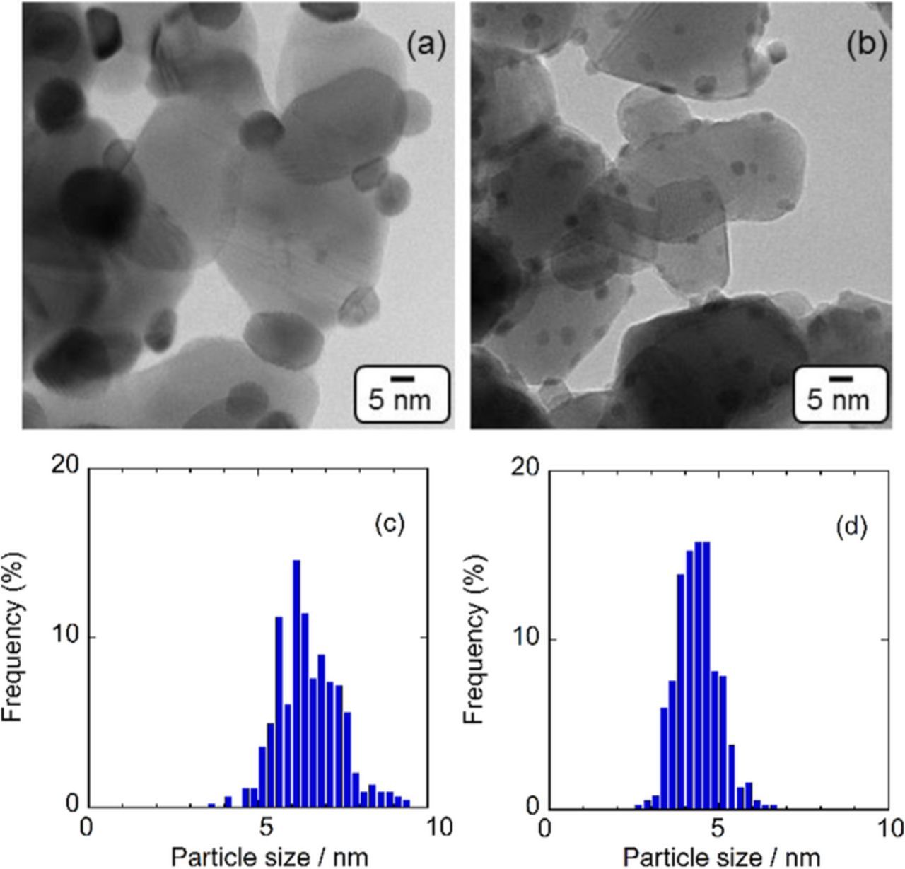
Figure 1. TEM images and Pt particle size distribution of Pt/Ta-SnO2 (a) (c), PtRu/Ta-SnO2 (b) (d).
The XRD peaks for the Pt in Pt/Ta-SnO2, which were located around 2θ = 39.8°, 46.4° and 67.2° were slightly shifted to higher 2θ compared to those of pure Pt (Fig. 2), because the catalyst was sintered at 800°C in N2 atmosphere, which allowed elemental tin originating from the Ta-SnO2 support to diffuse into the Pt catalyst particles, converting them to a PtSn alloy, as seen below. No XRD peaks for the PtRu alloy on Ta-SnO2 were detected in Fig. 2. As discussed later, Sn diffused from the Ta-SnO2 to the catalyst during the heat-treatment procedure. Sn-rich Pt-Sn and Ru-Sn phases are known to exhibit low melting points (under 800°C).34 It is likely that the lack of clear crystallinity is due to the PtRu alloy particles, which were sintered at 800°C and quenched to room temperature, being originally in a disordered state, and the disordering was further promoted by the additional diffusion of elemental Sn into the particles from the oxide substrate.
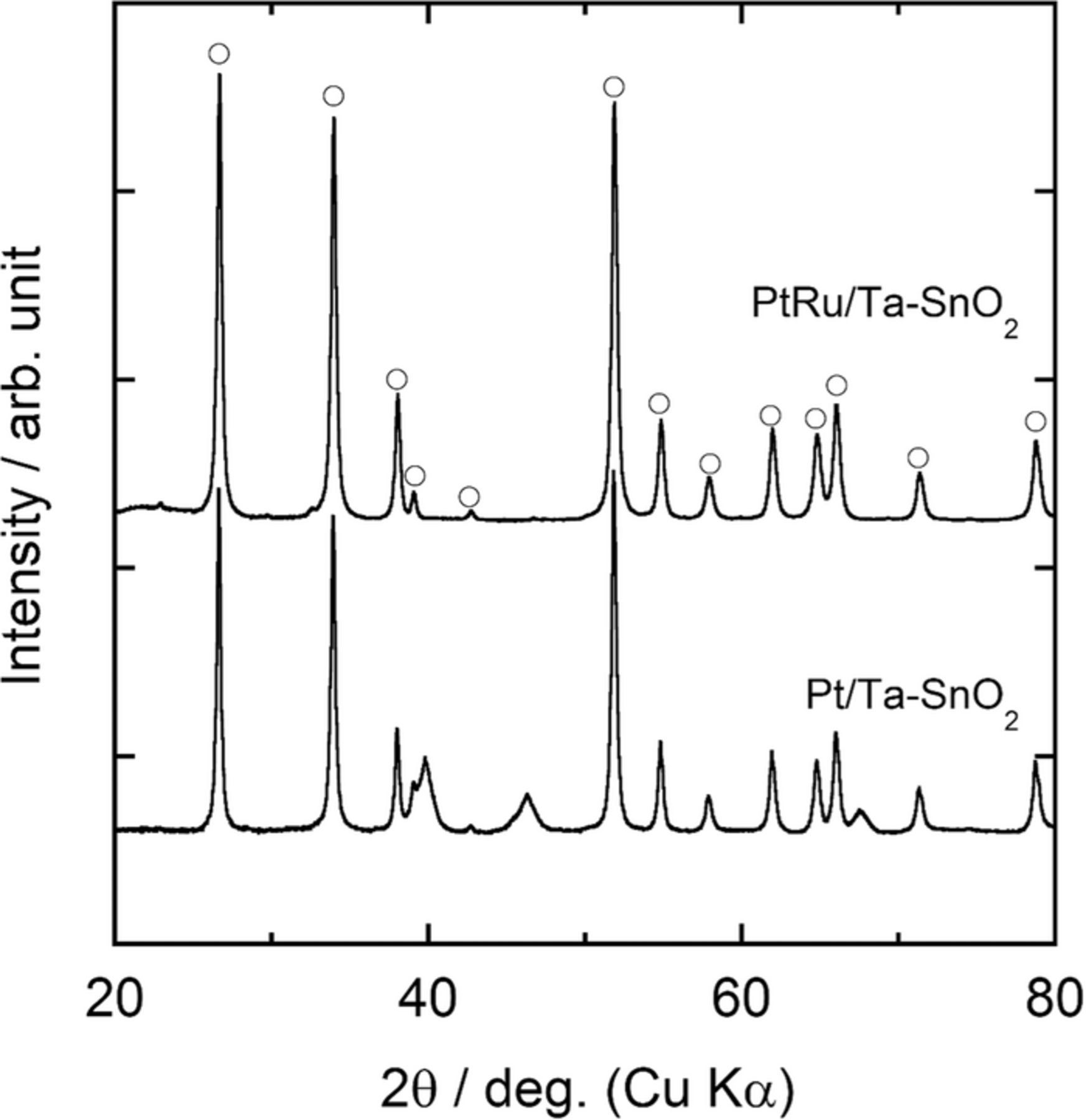
Figure 2. XRD patterns of Pt/Ta-SnO2 and PtRu/Ta-SnO2. Each XRD peaks of Ta-SnO2 was marked by open symbols.
The XPS spectra of Pt and Sn are shown in Fig. 3 for Pt/Ta-SnO2 (a, c) and PtRu/Ta-SnO2 (b, d), respectively. Almost no shifts (≤0.1 eV) of Pt 4f binding energies for PtRu/Ta-SnO2 as well as Pt/Ta-SnO2 were observed, in comparison with those of pure Pt metal. No noticeable shifts from a standard reference were observed for the Sn 3d binding energy peaks of the SnO2 substrates on either of the supported catalysts, probably due to the large excess of the Ta-SnO2 compared with the catalyst particles. However, clear peaks for metallic Sn appeared on both catalysts, even though no corresponding XRD peaks were observed. On the other hand, the line analysis of STEM-EDX with the HAADF-STEM images of Pt/Ta-SnO2 and PtRu/Ta-SnO2 (Figs. 4a, 4b) indicated that a relatively high content of Sn existed in each catalyst particle, and it gradually decreased with increasing distance from the contact with the support toward the outer particle surface; this was commonly observed in several tens of particles examined. It was also confirmed from the analysis that Pt and Ru were dispersed uniformly in the particles, forming the alloy but without exhibiting XRD peaks, as mentioned above, indicating disordering of the lattice structures due to the mixing with Sn. Also, the relative intensity (Sn versus Pt (Sn/Pt) of PtRu/Ta-SnO2 at the interface and center of the catalyst was higher in Pt. The amount of diffused Sn was larger in PtRu/Ta-SnO2 (Fig. 4b) than that in Pt/Ta-SnO2 (Fig. 4a). From these observations, shown in Figs. 2 to 4, we conclude that the metallic Sn diffuses from the Ta-SnO2 support into the noble metal catalyst during the sintering procedure and that the surface or a near-surface layer of the particles could involve Sn, Pt and Ru in the metallic state, as illustrated schematically in the inset of Fig. 4.
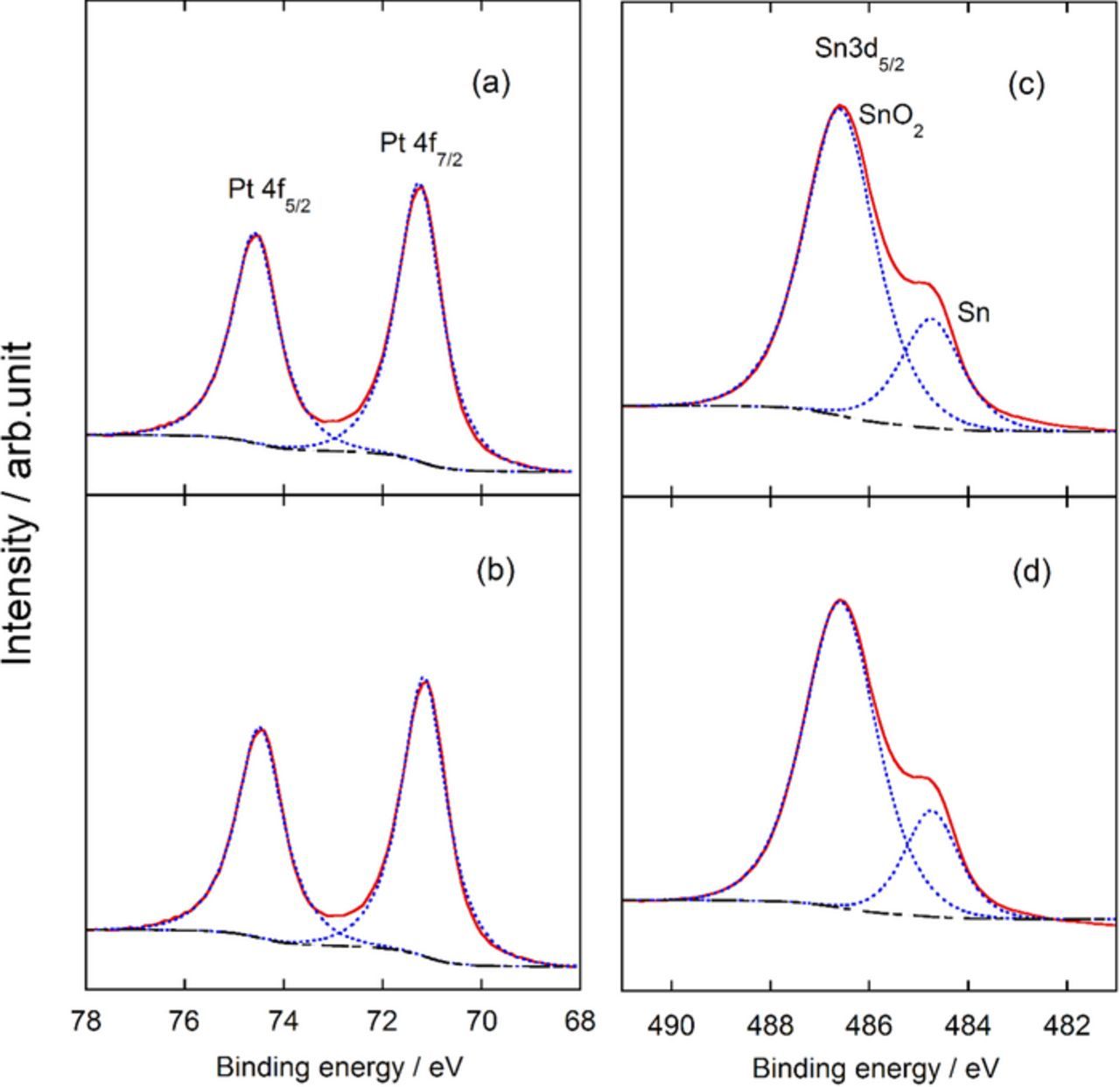
Figure 3. XPS spectra of Pt 4f and Sn 3d for Pt/Ta-SnO2 (a), (c), and for PtRu/Ta-SnO2 (b), (d).
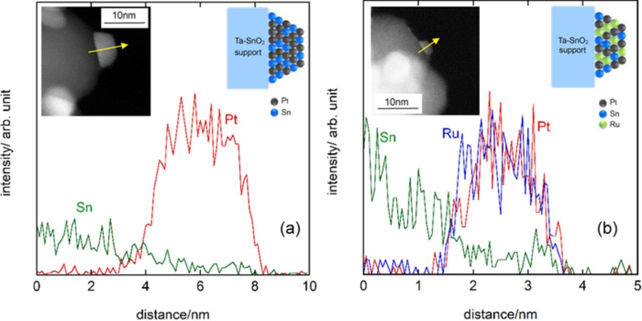
Figure 4. HAADF-STEM images and STEM-EDX profiles for Pt/Ta-SnO2 (a) and PtRu/Ta-SnO2 (b). Schematic drawings of the atomic distribution of Pt and PtRu on Ta-SnO2 sintered at 800°C in N2 atmosphere are shown as insets in each figure.
Electrochemical characterization of Pt/Ta-SnO2 and PtRu/Ta-SnO2
The CO stripping voltammograms for each catalyst in 0.1 mol dm−3 HClO4 solution saturated with N2 at 25°C are shown in Fig. 5. The onset potentials and peak potentials for CO oxidation reveal significant differences between these catalysts. The onset potentials decreased in the order c-Pt2Ru3/CB > Pt/Ta-SnO2 > PtRu/Ta-SnO2, and the peak potentials decreased in the order Pt/Ta-SnO2 > PtRu/Ta-SnO2 ≈ c-Pt2Ru3/CB. The lower onset potentials were associated with the presence of Sn, most likely due to the much greater ease with which Sn is oxidized to SnO2 (−0.106 V vs. RHE)35 compared with that with which Ru is oxidized to Ru2O3 (0.738 V vs. RHE).36 In contrast, the lower peak potentials were associated with the presence of Ru. Thus, the best overall behavior is obtained when both are present. In the bifunctional mechanism, both Sn and Ru can act to donate OH to assist in the oxidation of CO, with Sn doing so at a lower potential, but with Ru having higher intrinsic activity.37
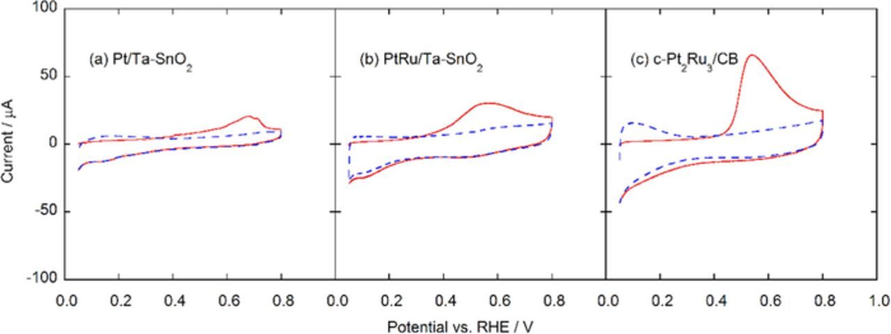
Figure 5. CO stripping voltammograms of Pt/Ta-SnO2 (a), PtRu/Ta-SnO2 (b), and c-Pt2Ru3/CB (c). The CO stripping charge was measured in N2-saturated 0.1 mol dm−3 HClO4 solution (CO-free condition) at 10 mV s−1 to oxidize the adsorbed CO (COads) on the working electrode.
The electrochemically active surface areas of each sample were estimated conventionally from the CO stripping peak areas (ECACO), assuming the oxidation of a monolayer of adsorbed CO on polycrystalline Pt requires 420 μC cm−2. The ECACO values for Pt/Ta-SnO2, PtRu/Ta-SnO2 and c-Pt2Ru3/CB were 28.1, 35.6 and 87.6 m2 gPt−1, respectively, referred to Pt weight. On the other hand, based on the mean particle sizes determined by TEM and their compositions, the specific surface areas can be calculated to be 44.4, 68.3 and 80.0 m2 gcat−1, which can be reduced to Pt weight-base values (ECATEM) of 44.4, 46.0, 45.0 m2 gPt−1, respectively. These values are not consistent with the ECACO values but nevertheless might be reasonable, because there were large difference among the catalysts in the components, compositions, surface states of the catalyst particles and their support materials, resulting in the large differences in the amounts of adsorbed CO on their surfaces. In other words, it is difficult to obtain reliable data of the specific surface area on such catalysts by methods applying gas-adsorption behavior, including ECACO. It is well known that the CO coverage and/or adsorption strength on Pt and Pt alloys depend upon various structural and electronic factors. This has been documented experimentally and theoretically in previous papers, for pure Pt, and for Pt-M alloys,42–45 and thus, it has been found that the apparent CO coverage on Pt and Pt-M surfaces (θ, %) does not always reach 100%.37–41 Therefore, in the present work, we have simply compared the catalytic behavior among them based on the Pt weight, or the geometric electrode surface area of the RDE, and the MEAs loaded with the same amounts of Pt.
The hydrodynamic voltammograms for the respective oxidation reactions of the h-POMM3 (mixture of 0.75 mol dm−3 formaldehyde and 0.5 mol dm−3 methanol, h-POR), 1.0 mol dm−3 of methanol (MOR), and 1.5 mol dm−3 of formaldehyde (FOR) in 0.1 mol dm−3 of HClO4 solutions saturated with oxygen at 80°C are shown in Figs. 6a–6c. The current density was based on the geometric electrode area, which corresponds to the same amounts of Pt loading, 11 μg cm−2. Notice, however, that the current densities for the MOR were multiplied by 10 in order to facilitate the comparison of the onset potentials, which were defined as the potentials observed at a current density of 10 μA cm−2. The onset potentials for the h-POR, MOR and FOR on Pt/Ta-SnO2 and PtRu/Ta-SnO2 shifted noticeably to lower potentials in comparison with those on c-Pt2Ru3/CB, except for the MOR activity being inferior on Pt/Ta-SnO2 and superior on c-Pt2Ru3/CB. The onset potentials for each fuel on these catalysts are summarized as a function of measurement temperature in Fig. 7. Those for the h-POR and FOR on Pt/Ta-SnO2 and PtRu/Ta-SnO2 were at least 0.2 V lower than those for c-Pt2Ru3/CB at measurement temperatures from ambient to 80°C, although the onset potentials for the MOR were more or less at the same level on each catalyst over the whole temperature range.
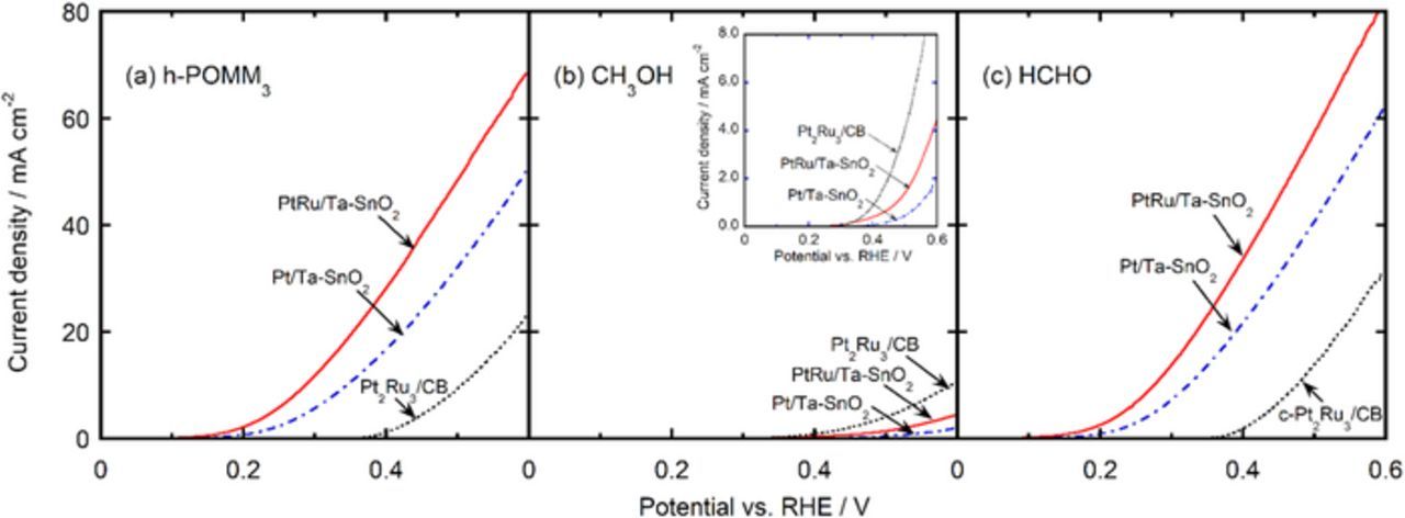
Figure 6. Hydrodynamic voltammograms at 80°C for the oxidation of 0.25 mol dm−3 h-POMM3 (mixture of methanol and formaldehyde, dissolved 0.5 and 0.75 mol dm−3, respectively) (a), 1 mol dm−3 methanol (b) and 0.75 mol dm−3 formaldehyde (c) on Pt/Ta-SnO2 (blue dash-dotted line), PtRu/Ta-SnO2 (red line) and c-Pt2Ru3/CB (black short-dotted line). The current densities are based on the geometric electrode area of the RDE, loaded with the same amounts of Pt (11 μg cm−2). The inset in (b) shows the current densities for the MOR on a ×10 more sensitive scale.
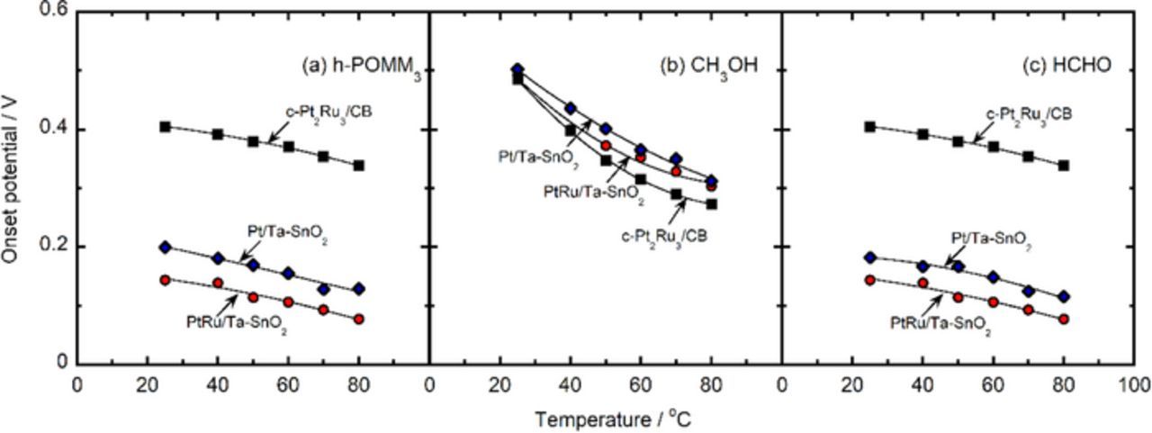
Figure 7. Onset potential for the oxidation of h-POMM3 (a), methanol (b) and formaldehyde (c) on Pt/Ta-SnO2 (blue diamonds), PtRu/Ta-SnO2 (red circles) and c-Pt2Ru3/CB (black squares) as a function of temperature.
Thus, the onset potentials for the h-POR and FOR appear to be consistent with those for CO oxidation already discussed. The major effect is due to the presence of Sn, while there is an additional effect of Ru. In contrast, the onset potentials for the MOR do not appear to be related to those for CO oxidation, and thus the rate-determining step is likely to be an earlier step in the overall process, for example, CO formation.36
As seen in Fig. 6, the current densities for the h-POR and FOR on Pt/Ta-SnO2 and PtRu/Ta-SnO2 were much higher than that on c-Pt2Ru3/CB over the whole potential region measured. However, the current density for the MOR, being one order of magnitude lower than those for the h-POR and FOR, was exceptionally lower on Pt/Ta-SnO2 than c-Pt2Ru3/CB.
Figure 8 shows the Pt-based mass activities at 0.50 V (MA0.50V) for the h-POR, MOR and FOR on the different catalysts as a function of measurement temperature. The MA0.50V values for the h-POR and FOR on Pt/Ta-SnO2, and PtRu/Ta-SnO2 were higher than those for c-Pt2Ru3/CB; in particular, those for the h-POR on PtRu/Ta-SnO2 and Pt/Ta-SnO2 were more than 4 times larger than that for c-Pt2Ru3/CB over the whole temperature range. The higher MA0.50V values for the MOR on c-Pt2Ru3/CB in comparison with those on Pt/Ta-SnO2 and PtRu/Ta-SnO2, shown in Fig. 8b, might be due to the larger specific surface area of the former, with mean particle size d = 3.5 nm, and also due to the higher CO tolerance with larger Ru content in the alloy.
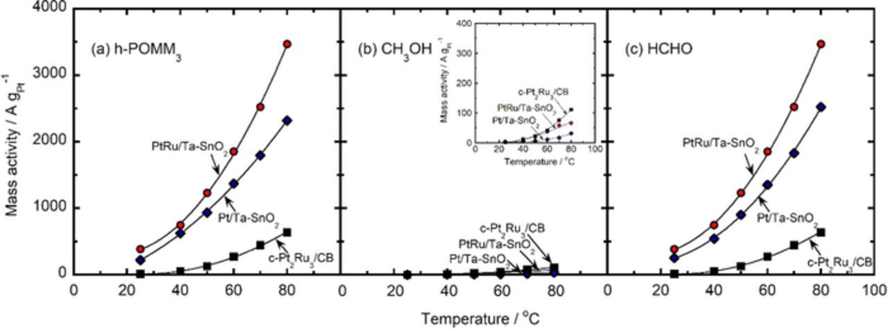
Figure 8. Pt-based mass activity at 0.50 V for the oxidation of 0.25 mol dm−3 h-POMM3 fuel (a), 1 mol dm−3 methanol (b) and 1.5 mol dm−3 formaldehyde (c) on Pt/Ta-SnO2 (blue diamonds), PtRu/Ta-SnO2 (red circles) and c-Pt2Ru3/CB (black squares) as a function of temperature. The inset in (b) shows the mass activities for the MOR on a ×10 more sensitive scale.
In the interest of completeness, we also checked the specific activities based on the catalyst area at 0.50 V (j0.50V) for the h-POR, MOR and FOR at 25°C. Each of the j0.50V values based on the ECACO (j0.50V,CO, A m−2ECA,CO) and ECATEM (j0.50V,TEM, A m−2ECA,TEM) of PtRu/Ta-SnO2, Pt/Ta-SnO2, and c-Pt2Ru3/CB are listed in Table I. Both sets of values were fairly consistent. We found that both the j0.50V,CO and j0.50V,TEM values for the h-POR, MOR and FOR for PtRu/Ta-SnO2 and Pt/Ta-SnO2 were much higher than those for c-Pt2Ru3/CB, except for the j0.50V,TEM for the MOR for Pt/Ta-SnO2 at 25°C. As already mentioned, this discrepancy might be related to differences in the surface composition of each catalyst. However, in general, the MA0.50V, j0.50V,CO and j0.50V,TEM values for PtRu/Ta-SnO2 were much higher than those for c-Pt2Ru3/CB.
Table I. Current density at 0.50 V versus specific surface area for the oxidation reactions of the hydrolyzed fuel of POMM3 (h-POR), methanol (MOR) and formaldehyde (FOR) measured by rotating disk electrode at 25°C.
| h-POR | MOR | FOR | ||||
|---|---|---|---|---|---|---|
| Catalysts | j0.50 V,CO* | j0.50 V,TEM** | j0.50 V,CO* | j0.50 V,TEM** | j0.50 V,CO* | j0.50 V,TEM** |
| PtRu/Ta-SnO2 | 7.34 | 5.68 | 1.64 | 1.27 | 13.3 | 10.3 |
| Pt/Ta-SnO2 | 5.34 | 3.38 | 1.00 | 0.63 | 9.49 | 6.00 |
| Pt2Ru3/CB | 0.41 | 0.81 | 0.64 | 1.26 | 0.76 | 1.49 |
*Current density per unit surface area corresponding to Pt as measured by CO stripping (A m−2ECA,CO). **Current density per unit surface area based on TEM estimation area (= 4πr2), where r is the average radius of each catalysts (A m−2ECA,TEM).
The hydrolysis of POMMn occurs promptly to produce formaldehyde and methanol under acidic conditions (Eq. 2) and supplies protons via oxidation, as shown below (Eqs. 3–12).
![Equation ([2])](https://content.cld.iop.org/journals/1945-7111/164/12/F1226/revision1/d0002.gif)
Formaldehyde branch:
![Equation ([3])](https://content.cld.iop.org/journals/1945-7111/164/12/F1226/revision1/d0003.gif)
![Equation ([4])](https://content.cld.iop.org/journals/1945-7111/164/12/F1226/revision1/d0004.gif)
![Equation ([5])](https://content.cld.iop.org/journals/1945-7111/164/12/F1226/revision1/d0005.gif)
![Equation ([6])](https://content.cld.iop.org/journals/1945-7111/164/12/F1226/revision1/d0006.gif)
Overall:
![Equation ([7])](https://content.cld.iop.org/journals/1945-7111/164/12/F1226/revision1/d0007.gif)
Methanol branch:
![Equation ([8])](https://content.cld.iop.org/journals/1945-7111/164/12/F1226/revision1/d0008.gif)
![Equation ([9])](https://content.cld.iop.org/journals/1945-7111/164/12/F1226/revision1/d0009.gif)
![Equation ([10])](https://content.cld.iop.org/journals/1945-7111/164/12/F1226/revision1/d0010.gif)
![Equation ([11])](https://content.cld.iop.org/journals/1945-7111/164/12/F1226/revision1/d0011.gif)
Overall:
![Equation ([12])](https://content.cld.iop.org/journals/1945-7111/164/12/F1226/revision1/d0012.gif)
In this research, M stands for either Ru or Sn, the latter having diffused into the Pt catalyst particle during the sintering procedure. The kinetics of the FOR and MOR at the anode are strongly affected by the poisoning due to the presence of CO as an intermediate on the Pt surface (Eqs. 3, 8). The adsorbed water or hydroxyl on the other metal (M) surface becomes an oxygen source, which accelerates the oxidation of the adsorbed CO to CO2 via the bifunctional mechanism (Eqs. 5, 10).14,15,45–47 The oxidation of CO adsorbed on the Pt surface of Eqs. 5, 10 is likely to be the rate-determining step (rds) for some of these oxidation reactions. The approximate activation energies for the FOR and h-POR of PtRu/Ta-SnO2 and Pt/Ta-SnO2 were 15–16 kJ mol−1, which were approximately half that for c-Pt2Ru3/CB (30 kJ mol−1), and which can be assigned to Eqs. 5, 10 as the rds. The activation energies for the MOR for PtRu/Ta-SnO2 and Pt/Ta-SnO2 were both 21 kJ mol−1, which was approximately two-thirds that for c-Pt2Ru3/CB (30 kJ mol−1). Thus, the rds for the MOR might be different from that for the h-POR and FOR on the PtRu/Ta-SnO2 and Pt/Ta-SnO2, as already mentioned, and might involve at least partial control by Eq. 8, which involves the breakage of four bonds, compared with only two for Eq. 3 for formaldehyde. The bond breakage steps would clearly have to be sequential but are shown for brevity here as single overall steps. A detailed mechanistic analysis is beyond the scope of the present work but will be pursued in continuing work. We have not been able to find relevant theoretical work that could help to elucidate the differences in behavior between the oxidation of formaldehyde and that of methanol. It is important to also note that the presence of Sn as well as Ru on the top surface or subsurface layer of the catalyst particles of Pt/Ta-SnO2 and PtRu/Ta-SnO2, as depicted in Fig. 4, may weaken the CO bonding strength at Pt sites, resulting in the enhancement of water adsorption and CO oxidation, as shown above.48–50
Single cell performance of Pt/Ta-SnO2 and PtRu/Ta-SnO2
Figures 9a–9c shows IR-free I-V curves for single cells using Pt/Ta-SnO2, PtRu/Ta-SnO2 and c-Pt2Ru3/CB as the anode catalysts (the same amounts of Pt loading, 0.30 mg cm−2) at 80 °C by supplying the h-POMM3 (mixture of methanol and formaldehyde, 2 and 3 mol dm−3, respectively, dissolved in electrolyte), 2 mol dm−3 methanol and 3 mol dm−3 formaldehyde, respectively. All of the cells, fed with the three types of fuels, exhibited open circuit voltages (OCVs) of approximately the same value, 0.8 V. It is reasonable to consider that the steady FOR and MOR in the h-POMM3 cells may continuously proceed at some intermediate cell voltage, i.e., an overvoltage that makes possible a balanced consumption of formaldehyde and methanol, so that there is no progressive accumulation of methanol at a particular current; this supposition is now being tested by use of a monitoring system during long term operation. An additional advantage of the use of the oxide support is discussed below.
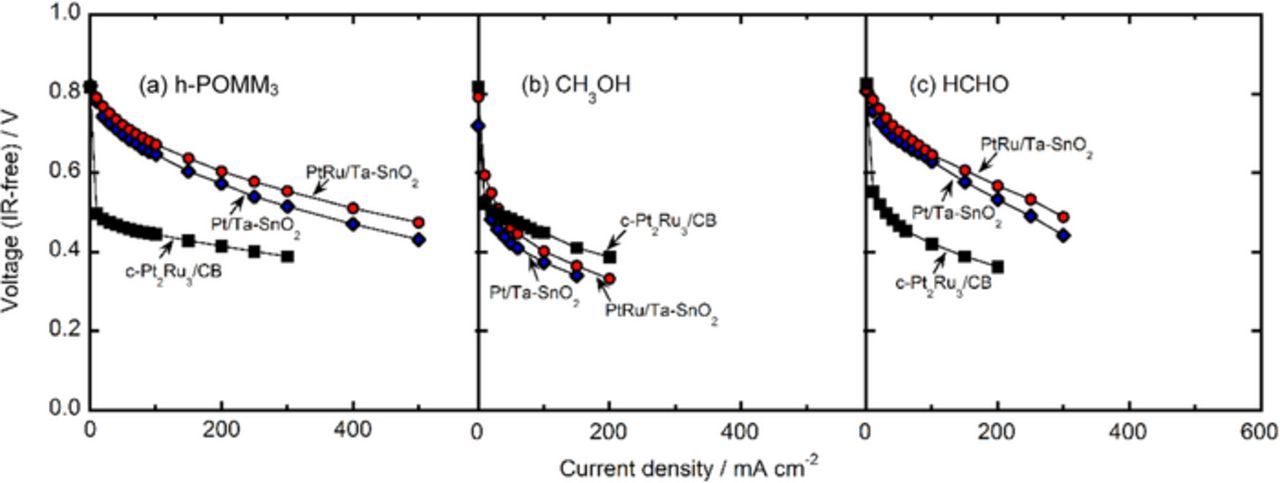
Figure 9. Performances of each single cell at 80°C, using Pt/Ta-SnO2 (blue diamonds), PtRu/Ta-SnO2 (red circles) and c-Pt2Ru3/CB (black squares) as the anode catalysts, fueling at 3 dm3 min−1 of (a) h-POMM3 (mixture of methanol and formaldehyde, dissolved 2 and 3 mol dm−3, respectively), (b) 2 mol dm−3 methanol and (c) 3 mol dm−3 formaldehyde.
Unlike the cells that utilized oxide supports, except the methanol cell, the cells that utilized c-Pt2Ru3/CB exhibited immediate voltage drops of 0.2–0.3 V from the OCVs as the current was increased, as seen in Figs. 9a–9c. This may be because the surface of the c-Pt2Ru3/CB catalyst is mostly covered with poisoning CO, even though a small number of CO-free sites might remain at the OCV of 0.8 V. As a result, the voltage drops quickly, i.e., a significant overpotential is required for the CO removal, as seen in Fig. 8, to enable the fuel oxidation to proceed at reasonable currents. In the methanol cells, an accumulation of poisoning CO presumably occurred at high coverages on the catalyst surfaces, even in the cells utilizing the Ta-SnO2 support. After the CO was removed from the surfaces in all of the cells utilizing c-Pt2Ru3/CB and at the methanol cell utilizing PtRu/Ta-SnO2 and Pt/Ta-SnO2, current could be drawn without further large voltage drops, at least up to 300 mA cm−2; for the CB-supported catalyst, this might be due to the well-known properties common to CB, i.e., good electronic conductivity and well-developed agglomerate structure.
On the other hand, we have reported the preparation of nano-sized oxide materials with the unique CB-like fused-aggregate network structure, as well as high electronic conductivity.28,33 The interconnected micropores of the Ta-SnO2 support in the CLs were expected to play the role of pathways for the supply of the liquid fuels and the efficient removal of product water and CO2. To our knowledge, gratifyingly superior performance found in this work, e.g., the OCV of 0.8 V and high current density of 500 mA cm−2 at cell voltages exceeding 0.45 V for the h-POMM3 cells, with the relatively low Pt loading of 0.3 mg cm−2, have never been achieved with conventional direct methanol fuel cells (DMFCs) utilizing PtRu/CB catalysts, even at Pt loadings a factor of 10 higher. Formaldehyde has an irritating odor and significant toxicity, but the POMMn fuels avoid these problems. From the viewpoint of the fuel regulations for European countries (EN 590), the POMMn (n = 3∼5) fuels are also suitable.8 With increasing n, the amount of formaldehyde increases and that of methanol decreases. There might still be further improvements in anodic catalysts for the MOR, but the present work suggests that a viable alternative could be the use of the hydrated POMMn (n = 3∼5) fuels, since they contain relatively high volumes of formaldehyde with increasing n value for the same volume of methanol, which can lessen the participation of the slower MOR, thus leading to a higher cell performance. Thus, the great merits of these h-POMMn fuel cells have been demonstrated here, in comparison with conventional DMFCs, in terms of performance, in addition to the intrinsic fuel properties of high volumetric energy density, high flash temperature and low toxicity. The output cell voltage, as well as the current density seen above for the h-POMMn/air cell, are still inferior to those for H2/air cells, but, in the former, the liquid fuel can be utilized directly, without the need for a fuel reforming/purification unit or heavy high-pressure gas cylinder for H2 storage. The achievement of such a high performance for the h-POR and FOR can be ascribed to the utilization of the Pt/Ta-SnO2 and PtRu/Ta-SnO2 catalysts described here.
Conclusions
Pt and PtRu catalysts supported on Ta-doped SnO2 (Pt/Ta-SnO2, PtRu/Ta-SnO2) were synthesized by the colloidal method for application as anodic catalysts for direct oxidation fuel cells fueled with liquid h-POMMn (n = 3∼8). We found that the onset potentials of the POM on Pt/Ta-SnO2 and PtRu/Ta-SnO2 were ca. 0.2 V lower than that for c-Pt2Ru3/CB. The Pt-based MA0.50V value on PtRu/Ta-SnO2 reached levels more than 4 times larger than that for c-Pt2Ru3/CB in the temperature range from 25°C to 80°C. Each of the Pt and PtRu catalysts, after sintering at 800°C in N2, became incorporated with elemental tin, which had diffused from the Ta-SnO2 support into the metallic phase. Part of the elemental tin was found to exist on the top surface of the catalyst as a metal, where it would help to enhance the oxidation reaction of CO, along with Ru, from the viewpoints of both the bifunctional mechanism and the ligand effect. The single cell performance using Pt/Ta-SnO2 and PtRu/Ta-SnO2 as the anode catalysts, while being supplied with either the h-POMM3 fuel or formaldehyde, was also found to be higher than that using c-Pt2Ru3/CB over the whole voltage range. The elemental tin diffusion from the Ta-SnO2 support to the catalyst nanoparticles and the unique fused-aggregate network structure of the Ta-SnO2 support are concluded to enhance the cell performance with POMMn being supplied as a fuel.
Acknowledgments
This work was partially supported by funds for the "Adaptable and Seamless Technology Transfer through Target-Driven R&D" Project (A-STEP) from the Japan Science and Technology Agency (JST), and JSPS KAKENHI grant Number 17H03410 from the Ministry of Education, Culture, Sports, Science and Technology.