
Abstract
Roughening of metal electrodes in batteries is detrimental as it can lead to metal dendrites. Such dendrites can cause short circuits when they grow from the metal electrode to the other one, as can happen during battery operation when metal is plated onto the surface of an electrode. It has been suggested that solid electrolytes of sufficient elastic stiffness can suppress electrode surface roughening and dendriting, although experimental evidence is now emerging that this possibility is not valid. To investigate whether metal electrode surfaces will roughen during battery charging we carry out a linear perturbation analysis. Our calculations explore whether an electrode surface with one-dimensional sinusoidal roughness will experience growth of its amplitude. We assess a linear elastic electrolyte that is a single ion conductor bonded to a metal electrode being plated by a cathodic ionic current. We find that long wavelength perturbations will always increase in roughness. High current densities during battery charging are found to permit growth of the amplitude of small wavelength roughness. The stiffness of the solid electrolyte is found to play a role in limiting the growth of roughness, but its effect can always be overcome at high current densities and for long wavelength protrusions.
Export citation and abstract BibTeX RIS
Lithium ion batteries with metal electrodes are attractive for next generation energy storage, as they offer advantages in regard to specific energy density storage, on both mass and volume bases.1,2 However, a common problem in the utilization of lithium metal electrodes is the growth of dendrites during battery charging as lithium is plated onto the negative electrode.3–5 These dendrites can initiate at microstructures and perturbations on the surface of the electrode,4–6 and take the form of a mossy growth,4 needle-like protrusions4 or globular structures.7 Systems with liquid electrolytes allow dendrites to grow freely,8–11 whereas a solid electrolyte can suppress or inhibit this possibility.4,12
However, the use of solid electrolytes for the purpose of suppressing dendriting has met with mixed success. Some solid electrolytes are thermoplastic polymers, usually in the form of a gel with an electrolyte solvent, e.g. polyethylene oxide (PEO) infiltrated by a lithium-based salt as the ionic path. Such materials are used above their glass transition temperature so that stiffness is compromised. Despite this feature PEO can tend to suppress needle-like and mossy dendrites but suffers from microscopic lithium protrusions and intrusions.13–15 However, there is evidence that dendrite growth in PEO can occur at all current densities.10 To enhance resistance to dendriting, polymer electrolytes can be stiffened by cross-linking15,16 or through use of double network gel strategies,17 or can be replaced by a zwitterionic copolymer as a better comprise between conductivity and stiffness.18 In addition, a stiff phase such as polystyrene (PS) can be introduced by diblock19 and triblock20 copolymer routes to combine it with PEO, still with its ionic conducting infiltrated lithium-based salt (PS-PEO). Despite these approaches to avoid dendriting, such materials still suffer, though to a lesser extent, from globular protrusions.7
Ceramic electrolytes can also be used with the advantage of greater elastic stiffness. However, ceramics are prone to cracking due to lithium insertion in defects and grain boundaries.21,22 Porz et al.22 comment that the tendency for dendriting in cracks to occur in both polymers and ceramics is independent of the solid electrolyte shear modulus.
Some progress has been made analyzing the tendency for dendrites to form through use of linear stability theory.23 Aogaki and Makino24 considered the shape stability of an electrode being plated from a liquid electrolyte, an approach followed up recently by Tikekar, Archer and Koch25 who studied structured electrolytes but neglected their elastic stiffness. Monroe and Newman12 propose a linear stability analysis of sinusoidal protrusions of lithium into an elastic electrolyte to determine when the amplitude of the perturbations will grow. In their analysis the presence of stress in both the electrode and the electrolyte affects the electrochemical kinetics at the interface. However, the mechanical stress field derived in their analysis does not satisfy force balance at the electrode – electrolyte interface. To achieve the perturbed sinusoidal shape that Monroe and Newman12 assumed in their analysis, external tractions must be imposed directly at the electrode – electrolyte interface, leading to the mechanical stress field that affects the electrochemical kinetics. However, such external tractions are absent in reality, and the effect of the resulting stress field on the electrochemical kinetics at the interface cannot be justified. In further work, Tikekar, Archer and Koch26 include a correct analysis of the elasticity at the roughening interface between a metal electrode and a solid electrolyte. However, they use assumptions regarding electrochemical kinetics at the interface that differ from the other treatments discussed above. Ahmad and Viswanathan27 later repeated the Monroe and Newman12 analysis, but the lack of force equilibrium at the electrode – electrolyte interface remains present in that solution. These same authors also carried out an analysis with anisotropic elastic properties for the materials involved,28 but leave in place the lack of equilibrium at the electrode – electrolyte interface.
Barai, Higa and Srinivasan29 avoid the need to apply tractions at the electrode – electrolyte interface by use of a stress-free configuration for the lithium that has sinusoidal perturbations on the surface in contact with the electrolyte, which, in turn, has a flat surface in the stress-free state. However, the contact between the electrolyte surface and that of the lithium is achieved by applying an external compressive stress, with the mechanical problem solved by the finite element method. As a result, the electrochemical kinetics at the interface are influenced by the net compressive stress and not just by the differences in stress between the peaks and the valleys of the sinusoidal perturbation. Such a net compressive stress is likely to favor the anodic reaction everywhere on the interface and inhibit the cathodic one everywhere. However, the average compressive stress, to 1st order for low amplitude interface undulations, will not affect the tendency for roughness to grow or diminish. Intuitively, this can be understood from the fact that the average compressive stress has the same effect at both the undulation peaks and at the bottom of the valleys, so that, for low amplitude roughness, it does not favor the enhancement nor the diminution of the amplitude of the undulations. Barai et al.30 extend their work to include additional effects in the electrochemistry and mechanics and appear to continue to apply the net compressive stress to the interface. They also follow up these efforts by presenting a comprehensive study of the effect of compressive stress and electrolyte transport properties on lithium dendrite growth.31
An additional contribution to the study of linear instability of shape perturbations of electrode – electrolyte interfaces is carried out by Natsiavas et al.,32 who used concepts introduced by Srolovitz33 to study the effect of prestress in electrolyte and electrode at their interface. However, this prestress is parallel to the interface and the effect of stress normal to the interface does not seem to have been assessed.
In this paper we carry out the linear analysis of the stability of sinusoidal perturbations of the surface of an elastic metal electrode that is being plated electrochemically from an elastic solid electrolyte. The stress-free shape of the solid electrolyte is a half space with a flat surface as shown in Figure 1a. The stress-free shape of the metal electrode is a half space with sinusoidal furrows of amplitude (i.e. height) ΔM as shown in Figure 1a. We assume that the sinusoidal shape pre-exists or has arisen through non-uniform deposition from the electrolyte, and that the amplitude of the furrows is small compared to their wavelength L. The metal and the solid electrolyte are assumed to be bonded together as shown in Figure 1b, with no stress applied externally. Therefore, the average stress at the electrode-electrolyte interface is zero. As a consequence, we omit any overall effect that stack pressure will have on the redox reactions, such as increasing the rate of the anodic reaction and diminishing that of the cathodic one. While stack pressure is an important feature of the technology of battery layups, for clarity we omit its effect in the current treatment and leave it for future effort. Nevertheless, we point out that stack pressure can have the effect of keeping the electrode and electrolyte in contact across the interface despite the roughness, obviating the need to assume bonding for our solution.
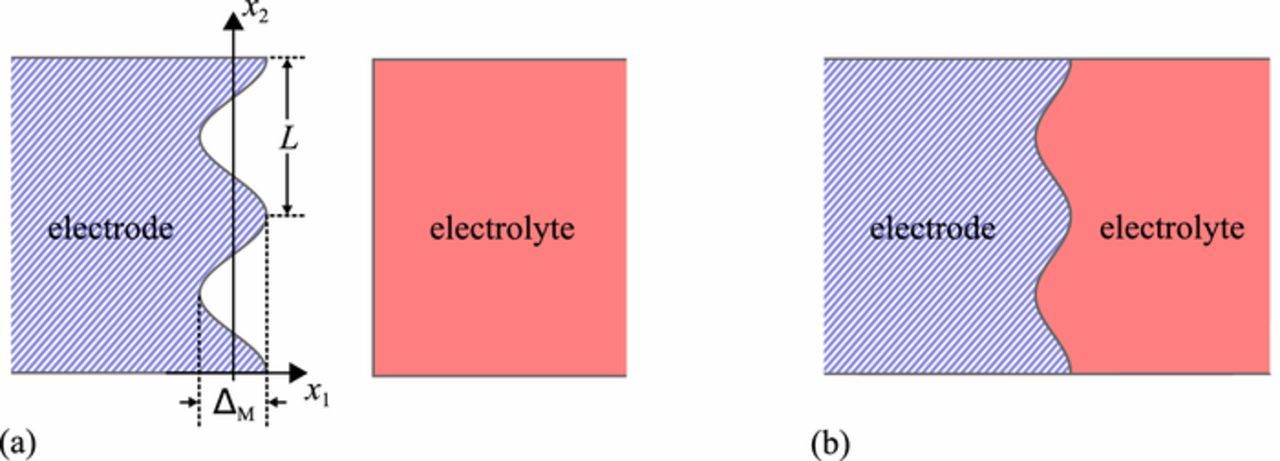
Figure 1. (a) Undeformed shapes of the electrode and electrolyte. Due to non-uniform deposition, the electrode has a sinusoidal surface, but the electrolyte surface is flat. (b) Deformed shape of the electrode and electrolyte. The two components are bonded together and elastic deformation has occurred, distorting them both, flattening the wavy surface of the electrode and causing the surface of the electrolyte to be wavy.
When the electrolyte is bonded to the electrode and there is roughness of the electrode surface, elastic deformation of both the electrolyte and the electrode lead to non-uniform stresses locally, notably compression across the interface at the peaks of the furrows and tension across the interface in the valleys. The tension is assumed to arise due to a bonded state between the electrolyte and the plated metal on the electrode. Evidence that such bonding prevails between metal electrodes and some solid electrolytes is present in images shown by Harry et al.7
We use a modified form of the Butler-Volmer equation to describe electrochemical kinetics at the electrolyte-electrode interface.34 Stresses there are assumed to affect the electrochemical kinetics of the deposition process, as will be explained below. The compression at the peaks and the tension in the valleys will combine to tend to suppress growth of the height of the furrows. The furrows will also cause non-uniformities in the ionic current density and the electric field in the electrolyte, an effect that is known to encourage the growth of the perturbation amplitude. For simplicity, we assume that the solid electrolyte is a single ion conductor so that the counter ions are immobilized within it. We also assume that the metal electrode is highly conductive of electrons so that the electric potential within it is uniform. The analysis is carried out at a fixed uniform current density at infinity in the electrolyte, and conditions causing the height of the furrows to grow are identified.
We note that our use of a single ion conductor as the electrolyte precludes important phenomena that can occur in binary ion conductors. Spatially homogeneous single ion conductors, operating in conditions of charge neutrality, retain a nearly uniform density of positively charged ions that sustain the current. As a result, there is a lack of the significant swelling of the electrolyte that can occur in binary conductors associated with diffusion of the anion. As a consequence, mechanical stress due to swelling plays only a small role in driving ionic transport within the electrolyte, and therefore we omit its effect. Furthermore, the combined effects of thermodynamics and kinetics are likely to be such that pressure gradients have only a negligible influence on the current density in single ion conductors, and therefore we omit its influence on the current density. Likewise, the concentration of cations will be close to being uniform, and therefore the associated gradient will be small in magnitude, so we neglect the effect it has on the current density too. Similarly, there is likely to be little effect of stress in the electrolyte on the redox reactions that transport ions across the electrolyte – electrode interface, as we observe that the partial molar volumes of cation defects in it are likely to be small. Therefore, we neglect that effect as well.
In contrast, the concentration of ions in binary conducting electrolytes tends to be non-uniform, leading to a number of effects that can influence the morphological stability of the electrolyte – electrode interface. The presence of stress in the electrolyte can influence its ionic transport characteristics. Similarly, the presence of stress can significantly affect the chemical potential of positively charged ions within the electrolyte and thus modify the rates of the redox reactions that carry ions across the electrolyte – electrode interface. In addition, depletion of the salt in the electrolyte near the interface can modify transport of ions adjacent to the electrode. Ganser et al.34,35 show that, in combination in a binary conducting electrolyte, these phenomena can have a significant influence on the morphological stability of the metal electrode interface. Therefore, our analysis, focusing on a single ion conducting electrolyte, may be unreliable when applied to electrode interfaces adjacent to binary ion conducting materials. Nevertheless, as a first step we apply our model not only to ceramic electrolytes that are single ion conductors but also to polymer ones that are binary ion conductors.
In addition, the scale of roughness that we consider will be in the micron range and not nanoscale. Therefore, we omit surface and interface energy from our analysis as it has been shown to be only significant when the protrusions are nanoscale.36
Effect of Stress on Electrochemical Deposition Kinetics
We use the model developed by Ganser et al.,34 derived for a monovalent redox reaction, to characterize how stress affects the kinetics of metal deposition by electrochemistry. In this model, derived from transition state theory following the approach of Bockris, Reddy and Gamboa-Aldeco,37 the presence of stress and mechanical phenomena in both the electrode and the electrolyte can affect the equilibrium potential of the interface and the exchange current density. However, the Butler-Volmer equation remains unchanged from its classical form, namely
![Equation ([1])](https://content.cld.iop.org/journals/1945-7111/166/6/A984/revision1/d0001.gif)
where i is the current density across the interface, positive when anodic,  is the exchange current density, β is the symmetry factor lying between zero and 1, F is Faraday's constant, R is the gas constant, T is the absolute temperature and η is the overpotential given by
![Equation ([2])](https://content.cld.iop.org/journals/1945-7111/166/6/A984/revision1/d0002.gif)
where ϕetrode is the potential in the electrode adjacent to the interface with the electrolyte, ϕelyte is the potential in the electrolyte adjacent to that interface and U is the equilibrium potential of the electrode relative to the electrolyte. In the model of Ganser et al.34 this parameter is consistent with the Nernst equation37 and is given by
![Equation ([3])](https://content.cld.iop.org/journals/1945-7111/166/6/A984/revision1/d0003.gif)
where μetrodeM is the chemical potential of the metal ion when it is in the electrode and μelyteM is its chemical potential when in the electrolyte. Note that the conditions to be used in evaluating the chemical potentials in Eq. 3 are those adjacent to the electrode – electrolyte interface. Thus, in general, these chemical potentials can be influenced by mechanics and stress, just as they can be by any other non-ideality or departure from a datum state. However, we will narrow the dependencies of these chemical potentials below to address the specific case that we will analyze. The exchange current density, for cases where configurational entropy plays no role in the state of the electrode and electrolyte, is given by34
![Equation ([4])](https://content.cld.iop.org/journals/1945-7111/166/6/A984/revision1/d0004.gif)
where io is a datum or reference exchange current density for the interface in the condition where the metal ion in the electrode has chemical potential μetrodeo and in the electrolyte has chemical potential μelyteo. The dimensionless parameters δetrode and δelyte determine how the energy barrier for the redox reaction is influenced by conditions in the electrode and the electrolyte.34 For example, if the chemical potential of the metal in the electrode increases, the barrier heightens by that increase multiplied by δetrode. Similarly, if the chemical potential of the metal ion in the electrolyte increases, the barrier heightens by that increase multiplied by δelyte. Thus, if the energy barrier is unaffected by those condition, both of these factors are zero.
In Appendix
We note that specific choices of values for δetrode and δelyte give rise to special cases that have been used in the literature.12,37–42 Explicitly, we mention only that the choice δetrode = 1 − αM and δelyte = αM makes Eq. 4 behave somewhat similarly to a formulation used by Monroe and Newman,12,38 with αM = 1 a notable special case.
Metal electrode and single ion conducting solid electrolyte
We now specialize the formulation of Butler-Volmer kinetics to an interface between a metal electrode and a single ion conducting solid electrolyte. For the solid electrolyte, we assume that charge neutrality prevails, a condition that is known to be relatively accurate except in the very thin double layer near an electrode.35,37,39 As a result of electroneutrality the concentration of mobile positively charged ions is exactly the same as the concentration of immobile negatively charged ones, which we assume to be uniform. As a consequence, and due to only infinitesimal strains, any temporal change of the concentration of positively charged ions anywhere in the electrolyte is 2nd order and can be neglected. In addition, this situation precludes significant swelling of the electrolyte. As a result of the lack of significant swelling, mechanical stress in the electrolyte has little effect on the chemical potential of the metal in the electrolyte, other than the metal's mole fraction share of the strain energy, which we assume to be small and negligible.43,44 Therefore, we neglect the contribution of stress to the chemical potential of the cation in the electrolyte. Thus the chemical potential of the metal ion in the electrolyte is taken to be constant, uniform and independent of stress, and we designate it to be such that
![Equation ([5])](https://content.cld.iop.org/journals/1945-7111/166/6/A984/revision1/d0005.gif)
so that the chemical potential of the metal ion is its reference value used in Eq. 4. Note that, as far as Eq. 4 is concerned, the effect of this choice can also be achieved by use of δelyte = 1 − β.
The chemical potential of the metal in the electrode is dependent on stress from 2 sources. One source is the strain energy of the metal in the presence of stress, and the other is the effect of normal stress on the metal electrode at the interface with the electrolyte.33 These aspects of stress affect the chemical potential of the metal in the electrode such that33
![Equation ([6])](https://content.cld.iop.org/journals/1945-7111/166/6/A984/revision1/d0006.gif)
where σn is the normal stress on the surface of the metal electrode, ΩM is the molar volume of the metal and ΨM is the strain energy density in the metal at the interface. Note that in our treatment tensile stresses are positive and compressive ones are negative. In Eq. 6 if the normal stress component σn is positive, i.e. tensile, there is a greater driving force for the metal to plate onto the electrode and if σn is negative, i.e. compressive, there is a greater driving force for the metal to be stripped. Note that the strain energy term has a negative sign because it includes the potential energy of the applied loads that is contributed by elastic strain and that contribution has been combined with the strain energy. However, the contribution associated with the strain energy as given in Eq. 6 is typically negligible compared to the term σnΩM, though the strain energy term can be important in certain circumstances.32,33,44 Therefore, we will omit the contribution from ΨMΩM on the grounds that it is 2nd order, as discussed by Ganser et al.34 among others. We note that in Appendix
The results just described enable us to rewrite Eq. 4 as
![Equation ([7])](https://content.cld.iop.org/journals/1945-7111/166/6/A984/revision1/d0007.gif)
This further simplifies if we assume that both β = 1/2 and δetrode = 1/2. With this value of δetrode, the transition barrier height for the redox reaction increases by 50% of any increase in chemical potential of the metal in the electrode. Specifically, given our model of chemical potential of the metal in the electrode, the barrier height is lowered by σnΩM/2 compared to the value prevailing in the absence of a normal stress across the interface. With β = δetrode = 1/2 Eq. 7 becomes
![Equation ([8])](https://content.cld.iop.org/journals/1945-7111/166/6/A984/revision1/d0008.gif)
Therefore, in this case there is no change to the exchange current density when normal stress is present.
The equilibrium potential at the interface is affected by the presence of stress as well. From Eqs. 3, 5 and 6 we deduce that
![Equation ([9])](https://content.cld.iop.org/journals/1945-7111/166/6/A984/revision1/d0009.gif)
In view of this, we rewrite the equilibrium potential as
![Equation ([10])](https://content.cld.iop.org/journals/1945-7111/166/6/A984/revision1/d0010.gif)
where
![Equation ([11])](https://content.cld.iop.org/journals/1945-7111/166/6/A984/revision1/d0011.gif)
With β = 1/2, this permits us to restate the Butler-Volmer equation from (1) as
![Equation ([12])](https://content.cld.iop.org/journals/1945-7111/166/6/A984/revision1/d0012.gif)
or
![Equation ([13])](https://content.cld.iop.org/journals/1945-7111/166/6/A984/revision1/d0013.gif)
Therefore, the presence of stress at the interface, when it produces a positive, normal stress on the surface of the metal, given our assumptions, reduces the anodic contribution to the current density across the interface and increases the cathodic contribution. In contrast, when the normal stress is compressive, the anodic contribution to the current density is increased while the cathodic term is decreased. These outcomes are intuitively logical since tension across the interface is increasing the rate at which metal is plated onto the electrode, while compression increases the rate at which metal is stripped from the electrode.
Stress at the Interface
We consider an electrode that has acquired a shape on its interface surface given by
![Equation ([14])](https://content.cld.iop.org/journals/1945-7111/166/6/A984/revision1/d0014.gif)
We note that this shape is that which the electrode surface will have in the absence of stress. However, it is bonded to the surface of the electrolyte, whose undeformed, stress-free shape has a flat surface as shown in Figure 1a. Therefore, both the electrode and the electrolyte must deform to accommodate the fact that they are bonded together. Such deformation causes elastic stress. We note that the average normal stress on the interface will be zero as we apply no external tractions to the system. Therefore, some locations on the interface, such as at x2 = 0, will be in compression, whereas other locations, such as at x2 = L/2, will be in tension. As noted above, this latter condition implies that the metal is bonded to the electrolyte when it emerges from the electrolyte during plating so that the tensile stress cannot relax.
We assume that both the electrode and the electrolyte remain elastic during plating of metal onto the electrode, and that the behavior is plane strain. We further assume that both the electrolyte and the electrode are linear elastic and isotropic, and that the electrode has shear modulus GM and Poisson's ratio νM, while the electrolyte has shear modulus GC and Poisson's ratio νC.
The solution to the elastic problem that results from bonding the electrode to the electrolyte can be obtained by a number of methods including use of complex variable methods.45 The complete solution for electrode and electrolyte that extend to infinity on either side of the interface is given in Appendix
The resulting in-plane stress at the interface in the metal, from Eqs. B27, B28, B29 and B30, is
![Equation ([15a])](https://content.cld.iop.org/journals/1945-7111/166/6/A984/revision1/d0015.gif)
![Equation ([15b])](https://content.cld.iop.org/journals/1945-7111/166/6/A984/revision1/d0016.gif)
![Equation ([15c])](https://content.cld.iop.org/journals/1945-7111/166/6/A984/revision1/d0017.gif)
![Equation ([15d])](https://content.cld.iop.org/journals/1945-7111/166/6/A984/revision1/d0018.gif)
with all other stress components zero, and where the coordinate system is shown in Figure 1a. We note that this solution is valid when ΔM/L ≪ 1. We reiterate that we have not included spatially uniform stress components for σ11, σ22 and σ33 in the electrode and in the electrolyte that would account for stack pressure. Instead we focus on the elastic stresses due to the sinusoidal roughness on the surface of the electrode in the absence of a stack pressure so that we can identify the effects these stresses have on growth or suppression of roughness.
Because of the fact that ΔM/L ≪ 1, the outward unit normal to the sinusoidal surface of the metal electrode varies negligibly and, to 1st order, is everywhere equal to the unit vector parallel to the x1 axis. Therefore, to 1st order, σn = σ11 at the interface and thus from Eq. 15a we have
![Equation ([16])](https://content.cld.iop.org/journals/1945-7111/166/6/A984/revision1/d0019.gif)
for use in Eq. 13.
Leading Order Ion Transport Solution
The leading order solution is that for a flat interface. We assume that metal is being plated on the electrode, and that the process is occurring at a constant rate. We set the potential of the electrode at the interface to zero, and prescribe the cathodic current density at the interface to be I > 0. We apply no external stress to the system, so for the leading order solution σn = 0 in Eq. 13, and all components of stress in both the electrode and the electrolyte are zero. The Butler-Volmer equation in 13 then reads
![Equation ([17])](https://content.cld.iop.org/journals/1945-7111/166/6/A984/revision1/d0020.gif)
Upon inversion, this provides
![Equation ([18])](https://content.cld.iop.org/journals/1945-7111/166/6/A984/revision1/d0021.gif)
where ϕ(x1, x2) is the electric potential in the electrolyte. The results will be planar throughout the treatment. For this reason, we omit the coordinate x3 and all terms in the through thickness direction as, other than σ33, all will be zero.
In the coordinate system of Figure 1a, the current density vector in the electrolyte is
![Equation ([19a])](https://content.cld.iop.org/journals/1945-7111/166/6/A984/revision1/d0022.gif)
![Equation ([19b])](https://content.cld.iop.org/journals/1945-7111/166/6/A984/revision1/d0023.gif)
Because the electrolyte is a single ion conductor its transport properties are taken to be ohmic, and the electric field in it is
![Equation ([20a])](https://content.cld.iop.org/journals/1945-7111/166/6/A984/revision1/d0024.gif)
![Equation ([20b])](https://content.cld.iop.org/journals/1945-7111/166/6/A984/revision1/d0025.gif)
where ρ is the resistivity of the electrolyte. Note that, in principle, pressure gradients and cation vacancy concentration gradients can affect cation transport rates in the electrolyte. However, we judge these contributions to be 2nd order compared to the effect of electric field and neglect them.
From Eq. 20 the electric potential in the electrolyte is
![Equation ([21])](https://content.cld.iop.org/journals/1945-7111/166/6/A984/revision1/d0026.gif)
where we have used the boundary condition in Eq. 18.
Higher Order Perturbation Solution
We perturb the leading order solution to add terms that can account for the sinusoidal shape of the interface, subject to Laplace's equation governing the electric potential. We seek a solution of the form
![Equation ([22])](https://content.cld.iop.org/journals/1945-7111/166/6/A984/revision1/d0027.gif)
where A and B are constants to be determined. They are appropriately small so that the added terms can be treated as small perturbations. The omitted terms are smaller still. We note that the added terms satisfy Laplace's equation because they are proportional to the real and imaginary part of e− ωz where ω and z are defined in Appendix
![Equation ([23])](https://content.cld.iop.org/journals/1945-7111/166/6/A984/revision1/d0028.gif)
where σon is given by Eq. C20 and ΔC by Eq. C7. As a consequence, the normal component of the current density at the interface is
![Equation ([24])](https://content.cld.iop.org/journals/1945-7111/166/6/A984/revision1/d0029.gif)
Stability of the Interface
The rate at which the protrusions grow is given by
![Equation ([25])](https://content.cld.iop.org/journals/1945-7111/166/6/A984/revision1/d0030.gif)
We rearrange this to read
![Equation ([26])](https://content.cld.iop.org/journals/1945-7111/166/6/A984/revision1/d0031.gif)
where κM & κC are defined in Eqs. B9 and B10. Since the metal electrode will always have a finite value for its shear modulus, and since we assume some degree of surface roughness exists at the outset, none of the terms on the left hand side of Eq. 26, other than dΔM/dt, can be zero. Therefore the coefficient of dΔM/dt in Eq. 26 is positive. Thus, if the right hand side of Eq. 26 is negative, the interface morphology is stable and the amplitude of the protrusions diminishes. If the right hand side of Eq. 26 is positive, the interface morphology is unstable, and the protrusions grow. Therefore, the stability criterion is
![Equation ([27])](https://content.cld.iop.org/journals/1945-7111/166/6/A984/revision1/d0032.gif)
That is, if 27 is satisfied, the protrusions will not grow, and in fact diminish in amplitude. However, the decay of the amplitude will be exponential in time, and therefore the protrusions cannot ever completely disappear. Thus, such protrusions will be left available to be grown again if the stability criterion in 27 is later violated.
We note further that GC(1 − νM) + GM(1 − νC) > 0 and Gc(5 − 6νM − 6νC + 8νMνC) + GM(3 − 4νC) > 0. Thus, if the term in brackets containing the current density is positive, the inequality in 27 compares quantities that are always positive. Therefore, if the term in the square brackets is positive, the left hand side of 27 can exceed the right hand side, and stability of the protrusions can be achieved for some wavelengths of the sinusoidal undulations. If the term in brackets containing the current density is negative, implying that δetrode < 0, all wavelength protrusions will grow, since the right hand side of Eq. 26 will then be positive. However, as will be seen below, for − ∞ < δetrode < 0 this condition arises at a finite, nonzero current density.
Dependence of Results on δetrode
δetrode≥0
We consider first the case where δetrode ≥ 0 implying that the term in square brackets in 27 is positive. We note that the stability criterion in 27 then implies that protrusions will always enlarge if the wavelength, L, for them is large enough; this is a common situation in materials science where long wavelength roughness is often predicted to grow.33 This situation arises because long wavelength disturbances induce less strain energy per unit area compared to short wavelength ones of the same amplitude.
In addition, the result in 27 shows that instability can always be induced by increasing the current density until the right hand side exceeds the left hand side. This point may be understood by consideration of Eq. 26. As the current density is increased, the coefficient of dΔM/dt in Eq. 26 remains finite and positive, and approaches an asymptotic value for very large values of I. Similarly, the 2nd term on the right hand side of Eq. 26 approaches an asymptotic value that is proportional, inter alia, to δetrode. However, the 1st term on the right hand side, always positive, increases linearly with current density, and thus the right hand side of Eq. 26 can always be made positive by a sufficiently high current density, so destabilizing the morphology of the interface.
The results in 27 also show that the electrolyte resistivity plays a role in the potential instability of the interface. The influence of the current density and the resistivity arise because, together, they determine how much difference the protrusion makes to the electric potential in the electrolyte adjacent to the interface.
An additional effect present in 27 is that stiffer electrolytes help to suppress the growth of protrusions to a greater extent than compliant electrolytes. This influence is delivered in conjunction with the metal molar volume, as, together, the electrolyte shear modulus and the metal molar volume, i.e. GCΩM, determine the level of stress generated at the interface per mole of metal deposited on the wavy surface of the electrode. We observe also that when GC = 0 protrusion of all wavelengths will grow. Such a situation represents a liquid electrolyte, showing that our criterion agrees with that of others for this case.8–11,24,25 We note, however, that liquids are binary ion conductors.37,39
The equality in 27 marks the conditions that divide unstable and stable conditions. Thus, when we allow 27 to be an equality and rearrange it as an expression for the wavelength L it gives an expression for the critical wavelength Lc. Above this wavelength, protrusions will grow and below it their amplitude will diminish. It is given by
![Equation ([28])](https://content.cld.iop.org/journals/1945-7111/166/6/A984/revision1/d0033.gif)
The influence of the elastic properties of electrode and electrolyte is difficult to discern from 27 and Eq. 28 because of the complexity of the expressions that contain the Poisson ratios. To simplify the situation for the purposes of improving insight, we can set νC = 1/2, a value relevant to a polymer electrolyte. We note that polymer electrolytes are typically binary ion conductors, so that our analysis is incomplete as it omits the effect of mobile counterions. As noted above, Ganser et al.34,35 have deduced that a combination of phenomena associated with the characteristics of binary ion conductors can influence the morphological stability of the electrolyte – electrode interface, and, in fact demonstrate that they can make it less stable. Nevertheless, in the spirit of initial exploration we apply our model to polymers even though they are binary ion conductors. With νC = 1/2 the criterion for stability in 27 becomes
![Equation ([29])](https://content.cld.iop.org/journals/1945-7111/166/6/A984/revision1/d0034.gif)
and Eq. 28 for the critical wavelength becomes
![Equation ([30])](https://content.cld.iop.org/journals/1945-7111/166/6/A984/revision1/d0035.gif)
In this case, other than the elastic shear stiffness of the electrolyte, mechanical properties of electrolyte and electrode play no role in the stability of the interface. Specifically, the elastic properties of the electrode play no role in endowing the interface with stability, nor do they destabilize the interface.
To gain further insight we choose the special case δetrode = 0.5, whereupon 29 becomes
![Equation ([31])](https://content.cld.iop.org/journals/1945-7111/166/6/A984/revision1/d0036.gif)
and Eq. 30 converts to
![Equation ([32])](https://content.cld.iop.org/journals/1945-7111/166/6/A984/revision1/d0037.gif)
These results make it clear that a stiff electrolyte is beneficial in helping to suppress the growth of protrusions. However, Eq. 32 indicates that the system becomes more unstable as the current density is increased, in the sense that this process will make shorter wavelengths unstable and allow them to increase their amplitudes.
The result in Eq. 32 shows that in this case the critical wavelength decreases monotonically with current density. Although not so easy to discern, this is also the case for the more general formula in Eq. 30. At very low current densities the critical wavelength given by Eq. 30 depends approximately on current density in the manner given by Eq. 32. At current densities very much larger than 2io the result in Eq. 30 is approximated by
![Equation ([33])](https://content.cld.iop.org/journals/1945-7111/166/6/A984/revision1/d0038.gif)
These observations show that the critical wavelength from Eq. 30 decreases monotonically with increase of current density for both low and high current densities. Study of Eq. 30 will convince one that the behavior in between low and high current densities is also monotonic.
The results in Eqs. 30 and 32 also show that no protrusions can remain immune to unstable growth of their amplitudes if the current density is high enough. This feature of the potential instability of the system carries over to the general case as given by Eq. 28. Of course, this aspect of the behavior of the interface is limited by the practical conditions of conductivity of the electrolyte that will constrain the magnitude of the current density. However, it is important to note that this limitation arises from the properties of the electrolyte and is not a constraint imposed by the behavior of the interface.
Because all the results above exhibit behavior that is monotonic with current density, we will proceed to give further illustrations through use of δetrode = 0.5, so simplifying the expressions we obtain. We are not proposing δetrode = 0.5 as the most realistic choice. Indeed, it seems more likely that δetrode = 0 is the more realistic choice, and others such as Monroe and Newman12 have used formulations that are akin to the choice δetrode = 0. However, the behavior in terms of current density is qualitatively the same for all positive values of δetrode and quantitatively little different from that which occurs for δetrode = 0.5. Therefore we proceed with the latter choice, but with the understanding that other choices of δetrode may be preferable as representations of transition state kinetics.
To represent a ceramic electrolyte we set νC = 1/4 in 27. Such a value is not exact for all ceramics, but is a reasonable choice. In addition we use νM = 1/3 to characterize a typical metal electrode. In this case the criterion in 27 becomes
![Equation ([34])](https://content.cld.iop.org/journals/1945-7111/166/6/A984/revision1/d0039.gif)
Similarly, Eq. 28 becomes
![Equation ([35])](https://content.cld.iop.org/journals/1945-7111/166/6/A984/revision1/d0040.gif)
Note that the approximate values on the right hand sides are reasonable as ceramic electrolytes will be significantly stiffer than metals such as lithium often used as electrodes. Compared to 31 and 32, 34 and 35 are predicting that the electrolyte must be 50% stiffer to achieve the same degree of stabilization of the interface. However, since ceramics are generally much stiffer than polymers, this requirement will be easy to attain.
Finally, we choose both Poisson ratios to be zero, at the lower end of common values, and find that 27 becomes
![Equation ([36])](https://content.cld.iop.org/journals/1945-7111/166/6/A984/revision1/d0041.gif)
while Eq. 28 becomes
![Equation ([37])](https://content.cld.iop.org/journals/1945-7111/166/6/A984/revision1/d0042.gif)
We infer from these estimates that the elastic properties of the electrode relative to the electrolyte make only a quantitative difference to the stability criterion and not a qualitative one. Our assessment of morphological stability of the interface thus differs from the criterion introduced for interface stability by Monroe and Newman,12 namely that the electrolyte shear modulus should be twice that of the electrode. We conclude that this proposed criterion of Monroe and Newman12 is not relevant to the stability of interfaces between elastic metal electrodes and single ion conducting elastic electrolytes. We also see no obvious reason why the situation should be different for binary ion conducting elastic electrolytes against metal electrodes.
δetrode<0
We now consider negative values for δetrode, although this seems unlikely. In this case, the term in the square brackets in 27 can be negative, although for small current densities it is positive. The change of sign occurs at  . Below this current density the right hand side of Eq. 26 can be negative, and therefore shorter wavelength protrusions can be stable against their amplitude enlarging. Above this current density, the right hand side of Eq. 26 is positive and all wavelength protrusions will experience growth of their amplitudes. A negative value of δetrode is therefore destabilizing.
Discussion
We noted above that Tikekar et al.26 correctly treat the elasticity of roughening at an electrode-electrolyte interface during metal deposition. However, in contrast to us they do not use Butler-Volmer kinetics at the interface, but instead use a form of the Nernst equation37 modified by the presence of hydrostatic stress in both the electrode and the electrolyte. In addition, the solid electrolyte they treat is a binary ion conductor. When we specialize their stability criterion to a single ion conductor with transport characteristics identical to those we have used, and when we omit interface energy, we find that their stability criterion predicts that the interface is morphologically unstable for all wavelengths of sinusoidal roughness. Their result is most easily assessed by choosing the Poisson ratios of both the electrode and the electrolyte to be ¼. In this case our stability criterion in 27, with δetrode = 0.5, becomes
![Equation ([38])](https://content.cld.iop.org/journals/1945-7111/166/6/A984/revision1/d0043.gif)
showing that protrusion of a given wavelength will not grow if the electrolyte is sufficiently stiff. Thus our assessment of the stability of the interface differs from that of Tikekar et al.26
We note that our analysis involves various idealizations, such as our assumptions regarding the stress-sensitivities of terms that enter the Butler-Volmer equation. In addition, our calculations pertain to an electrolyte that is of infinite thickness; as a consequence there is no direct interaction between the growing protrusion and the anode on the other side of the electrolyte, such as can occur through foreshortening of the distance between the growing protrusion and the anode. Another aspect of our analysis is that we assume uniform properties for the interface between the electrolyte and the metal electrode; this precludes an assessment of the role of heterogeneities in the interface resistance. Our model addresses only single ion conducting solid electrolytes and omits the additional complexities associated with ion transport and swelling that can occur in binary ion conducting solid electrolytes. Finally, the mechanical properties of both electrode and electrolyte are assumed to encompass only linear elasticity and omit phenomena such as plasticity in the metal electrode. It should also be noted that our stability assessment is confined to linear analysis, and thus limited to assessing whether morphological instability of the interface can be initiated from small amplitude roughness. It cannot address the question of whether the instability phenomenon is sustained as the protrusion enlarges.
We investigate the criteria in 27 and 28 to identify whether solid electrolytes are capable of suppressing the growth of lithium electrode protrusions that have a short enough wavelength to be troublesome in a solid state lithium ion battery. We consider a battery having a capacity of 5 mAh/cm2 being charged at 1C, so that I = 5 mA/cm2. We take the resistivity of the solid electrolyte to be 10 Ωm, which is at the upper end of the typical range (see references in Lin, Liu and Cui).46 The molar volume, ΩM, of lithium is 13 cm3 and Faraday's constant is 96485 C/mole. The criterion in 31 for polymer electrolytes, but with δetrode = 0.5, then leads to
![Equation ([39])](https://content.cld.iop.org/journals/1945-7111/166/6/A984/revision1/d0044.gif)
and 34 for ceramics gives us
![Equation ([40])](https://content.cld.iop.org/journals/1945-7111/166/6/A984/revision1/d0045.gif)
where, in both cases, the criterion determines those wavelengths that will not grow at the specified current density.
The shear modulus of the polymer electrolyte PEO19 can be 0.1 MPa at 90°C and this modulus has been measured to be lower.47 With a shear modulus of 0.1 MPa, 39 predicts that protrusions with wavelength greater than 0.3 μm will grow in amplitude at 1C. We consider such protrusions to be small enough in wavelength for them to grow into needle-shaped dendrites of the type that could penetrate through the electrolyte and cause a short circuit. In addition, the characteristics of PEO are often liquid-like as it is usually utilized above its glass transition temperature;19 for this reason, if for no other, such PEO is likely to be prone to dendriting. Other, stiffer values of the shear modulus of PEO systems have been observed,48,49 at 7 MPa and higher. At 7 MPa, according to 39, protrusions of wavelength greater than 24 μm will grow at 1C. We consider such wavelengths to be marginal in terms of the likelihood of them developing into needle-shaped dendrites of a dangerous character. However, if the charging rate is increased to 10C for a PEO that has shear modulus 7 MPa, protrusions of wavelength greater then 2.4 μm will grow. We consider them to be small enough to be dangerous as precursors of needle-shaped dendrite growth.
The shear modulus of the block copolymer electrolyte PS-PEO47 for useful compositions can be as low as 1 MPa. At that modulus 39 indicates that protrusions of wavelength 3.4 μm and greater will enlarge at 1C, while at a charging rate of 10C those greater than 0.3 μm will do so. We consider both of these wavelengths to be small enough that they are likely to lead to needle-shaped dendrites. Other measurements19,47 of PS-PEO systems lead to shear modulus values in the range 20 MPa to 30 MPa. At the lower value 39 predicts that protrusions with wavelengths greater than 68 μm will grow at 1C. We consider these to be flat enough in shape that they will probably not develop into needle-shaped dendrites. (We note that our assessment of this aspect of the situation in regard to whether the protrusions will lead to needle-shaped dendrites of lithium, or not, is intuitive and not based on any direct analysis. Guiding this intuition are the relative flatness and size of the protrusions compared to other likely battery dimensions, and the amount of plating that would be required to build the protrusions into substantial ridges.) Thus we conclude that at 1C a PS-PEO with a shear modulus of 20 MPa is likely to be effective at avoiding dangerous needle-shaped lithium dendrites. However, increase of the C-rate to 10 will lead to protrusions of wavelength greater than 6.8 μm growing in amplitude, putting the system back into danger territory for the potential growth of needle-shaped dendrites.
We now consider ceramic electrolytes, where our analysis is on firmer ground as they are single ion conductors. For LPS experimental50 and theoretical investigations51 suggest that its shear modulus lies in the range of 6.5 GPa to 15 GPa. The former value, when inserted into 40, indicates that protrusions of wavelength greater than 15 mm will grow at 1C. This seems safely beyond sizes that are likely to develop into dangerous needle-shaped dendrites and short circuits seem very unlikely from this source. Even at a charging rate of 10C matters seem to be satisfactory, with 40 predicting that only protrusions with wavelength greater than 1.5 mm will increase their amplitude. Since 10C is an ambitious charging rate, it seems likely that LPS is effective at controlling the growth of protrusions that can become troublesome short-circuited dendrites.
In the case of LLZO, Yu et al.52 identify its shear modulus to be in the range 50 GPa to 60 GPa. The inequality 40 at the lower value predicts that protrusions of wavelength 115 mm will grow at 1C. As with LPS, this wavelength seems to be safely beyond the scale at which troublesome needle-shaped dendrites are likely to develop. At 10C the situation also seems to be good with only those protrusions of wavelength greater than 11.5 mm likely to grow in amplitude. Thus we see that LLZO is likely to be even more effective than LPS at controlling the growth of protrusions that can become troublesome short-circuited dendrites.
While our assessment suggests that a stiff electrolyte cannot absolutely suppress morphological instability, it shows that a cell design and material choices can be formulated that are likely to achieve cell performances that will be free of roughening of the metal electrode/electrolyte interface. The criterion in 27 indicates that if the surface area of the interface is small, the electrolyte resistivity is low, the current density kept below a critical level, and the shear modulus of the electrolyte sufficiently high, such as is the case with ceramic materials, then roughness of wavelengths smaller than the width of the interface can be suppressed. Since roughness with a wavelength longer than the electrode width is irrelevant to it, such a design should be capable of avoiding the growth of electrode protrusions.
We note effects that can be associated with a solid electrolyte interface (SEI). When it remains intact, the SEI can play two possible roles. In one case, when it is very thin, it will modify the transition state barrier, thereby probably inhibiting the reaction rate. In another case, when it is thicker, the SEI will represent an electrolyte with its own properties. In this case there will be redox reaction rates that pertain to the properties of the SEI. A third possibility is that the SEI will fracture at the peaks of the undulations of the electrode surface as the SEI will be forced into tension there. This is likely to concentrate the current density at the peaks of the undulations that have been exposed. Such a situation will increase the plating rate at that location, and will have the effect of causing the amplitude of the undulations to grow more rapidly than when the SEI remains intact.
A final point is that while ceramic electrolytes seem likely to be able to suppress surface roughening of lithium electrodes, they may still be vulnerable to dendriting by the filling of pre-existing cracks with lithium that then forces the crack to propagate in the electrolyte.22 It is also known that dendrite growth can occur through grain boundaries.53 Hence, along with surface cracks, microstructural heterogeneity may lead to propagation of dendritic protrusions in ceramic electrolytes, thereby leaving them vulnerable to short circuits and failure.
Conclusions
We established that a metal electrode that has initial roughness and that is experiencing cathodic deposition will experience increase of the amplitude of the protrusions if they are long wavelength. This will occur no matter how stiff the electrolyte. Our investigations concern the case where the electrolyte is bonded to the electrode and the electrolyte is a single ion conductor.
In addition, we find that roughness of any wavelength will grow if the cathodic current density is sufficiently high no matter how stiff is the electrolyte. We conclude that an electrolyte that has a shear modulus twice as high as that of the electrode cannot always suppress growth of roughness protrusions. We further conclude that our criterion for interface morphological stability suggests that a cell design can be developed that is likely to obviate the growth of electrode protrusions.
List of Symbols
| °C | Celsius degrees |
| 1C, 10C | C-rates |
| A, B | Constants for general solution of Laplace's equation |
| C | Coulombs |
| cm | Centimeters |
| cs | Areal density of metal atoms on electrode surface |
| Ei | Components of electric field |
| e | Napier's constant |
| F | Faraday's constant |
| G | Shear modulus |
| GPa | Gigapascals |
| GC | Shear modulus of electrolyte |
| GM | Shear modulus of electrode |
| h | Hours or Planck's constant |
| I | Magnitude of current density in battery during charging |
| i | Interface current density, positive when anodic |
| i | In Appendix |
| i1, i2 | Components of current density |
| in | Current density normal to the interface |
 |
Exchange current density |
| io | Datum value for  |
| kB | Boltzmann's constant |
| L | Wavelength of roughness of electrode surface |
| MPa | Megapascals |
| m | Meters |
| mA | Milliamps |
| mm | Millimeters |
| Pa | Pascals |
| R | Gas constant |
| rf, rb | Forward and backward success frequencies for transition in redox reaction |
| ℜ | Real part of analytic function |
| T | Temperature |
| t | Time |
| u1, u2 | Components of displacement |
| x1, x2 | Cartesian coordinates |
| U | Equilibrium potential |
| Uo | Datum value for U |
| z | Complex variable |
 |
Complex conjugate of z |
Greek
| αM | Influence coefficient for effect of system energy states in redox reaction energy barrier |
| β | Symmetry factor for Butler-Volmer equation |
| Δ | Sinusoidal shape of electrode surface |
| ΔC | Amplitude of sinusoidal shape of electrolyte surface in the deformed configuration |
| ΔM | Amplitude of roughness of electrode surface |
| δelyte | Influence coefficient: Effect of electrolyte energy state on redox reaction energy barrier |
| δetrode | Influence coefficient: Effect of electrode energy state on redox reaction energy barrier |
| εij | Components of infinitesimal strain tensor |
| η | Surface overpotential |
| θ | Tangent angle to interface surface |
| κ | Auxiliary elastic modulus |
| κC | Auxiliary elastic modulus in electrolyte |
| κM | Auxiliary elastic modulus in electrode |
| μ | Chemical potential |
| μm | Microns |
| μbarrier | Energy barrier in transition state during redox reaction |
| μetrodee | Energy barrier in transition state during redox reaction in absence of electrical potential |
| μelytee | Electrochemical potential of metal ion in electrolyte |
| μelyteM | Chemical potential of metal ion in electrolyte |
| μetrodee | Electochemical potential of metal in electrode |
| μetrodeM | Chemical potential of metal in electrode |
| μelyteo | Datum value for μelyteM |
| μetrodeo | Datum value for μetrodeM |
| ν | Poisson's ratio |
| νC | Poisson's ratio of electrolyte |
| νM | Poisson's ratio of electrode |
| π | Ratio of circle circumference to circle diameter |
| ρ | Resistivity of electrolyte |
| σn | Mechanical stress normal to interface |
| σon | Half-amplitude of sinusoidal normal stress variation along interface |
| σij | Components of mechanical stress tensor |
| ϕ | Electric potential |
| ϕelyte | Electric potential in electrolyte |
| ϕetrode | Electric potential in electrode |
| χ | Analytic function of the complex variable |
| ΨM | Strain energy density in metal |
| ψ | Analytic function of the complex variable |
 |
Complex conjugate of ψ |
| Ω | Ohms |
| ΩM | Metal molar volume |
| ω | Auxiliary variable (See Eq. A7) |
Acknowledgment
The results presented were partly achieved during a four month visit of Markus Ganser in the group of Professor Robert McMeeking at the University of California, Santa Barbara. This stay was financially supported by a scholarship of the Karlsruhe House of Young Scientists (KHYS).
ORCID
Robert M. McMeeking 0000-0001-6369-7528
Markus Ganser 0000-0003-2063-1726
: Appendix A
Appendix. Derivation of the modified Butler-Volmer equation for an interface between a monovalent metal electrode and a single ion conducting electrolyte
We use Eq. 5 to model the chemical potential of metal ions in the electrolyte, neglecting the small contribution of mechanical strain energy. The electrochemical potential of metal ions in the electrolyte at the interface, given unit charge number, is thus
![Equation ([A1])](https://content.cld.iop.org/journals/1945-7111/166/6/A984/revision1/d0046.gif)
For the chemical potential of metal on the electrode surface we use Eq. 6, accounting for the effect of stress as dominated by the normal component at the interface;33 i.e. we neglect the strain energy term. Thus the electrochemical potential of the metal at the surface of the electrode is
![Equation ([A2])](https://content.cld.iop.org/journals/1945-7111/166/6/A984/revision1/d0047.gif)
As is conventional in the derivation of the Butler-Volmer equation,37 we introduce an energy barrier for the transition state and use the electric potential as a reaction coordinate.34 This leads to
![Equation ([A3])](https://content.cld.iop.org/journals/1945-7111/166/6/A984/revision1/d0048.gif)
where μbarrierc is the barrier peak energy in the absence of electrical potential and β, the symmetry factor, designates the location of the energy barrier on the reaction coordinate. From Eyring theory54 we compute forward and backward success frequencies
![Equation ([A4])](https://content.cld.iop.org/journals/1945-7111/166/6/A984/revision1/d0049.gif)
and
![Equation ([A5])](https://content.cld.iop.org/journals/1945-7111/166/6/A984/revision1/d0050.gif)
respectively for the probabilities of ions crossing in the forward direction from the electrode to the electrolyte and in the backward direction from the electrolyte to the electrode. In Eqs. A4 and A5 kB is Boltzmann's constant and h Planck's constant. The forward current density across the interface is Frf multiplied by the areal density, cs, of metal atoms in the electrode at the interface. Following logic stated by Ganser et al.,34 the backward current density is Frb multiplied by the same areal density cs, logic founded on the low probability of a successful metal ion jump from the electrolyte to other than a lattice position in the metal electrode.
From the above, we deduce that the net current density across the interface, positive when anodic, is
![Equation ([A6])](https://content.cld.iop.org/journals/1945-7111/166/6/A984/revision1/d0051.gif)
Equilibrium at zero current density occurs when Eqs. 2 and 3 are satisfied with η = 0, and then Eq. A6 can be rewritten as Eq. 1 with
![Equation ([A7])](https://content.cld.iop.org/journals/1945-7111/166/6/A984/revision1/d0052.gif)
Following Ganser et al.34 we now use an analogy to the Bronsted-Evans-Polyani principle as used e.g. in Huang, Zhang and Eikerling55 to deduce that the energy barrier can depend on the states of the electrode and the electrolyte, such that
![Equation ([A8])](https://content.cld.iop.org/journals/1945-7111/166/6/A984/revision1/d0053.gif)
where δetrode and δelyte are dimensionless coefficients. We note that in our case μelyteM − μoelyte = 0, but we include that term in Eq. A8 for completeness.
We insert Eq. A8 into Eq. A7 and obtain Eq. 4 with
![Equation ([A9])](https://content.cld.iop.org/journals/1945-7111/166/6/A984/revision1/d0054.gif)
Note that io depends only on reference or datum conditions of the system and therefore serves as a reference or datum value of the exchange current density.
: Appendix B
Appendix. Complete solution for the elastic stress in the electrode and electrolyte
The electrode and the electrolyte are in infinitesimal plane strain, so the solution can be stated in terms of complex variables as45
![Equation ([B1])](https://content.cld.iop.org/journals/1945-7111/166/6/A984/revision1/d0055.gif)
![Equation ([B2])](https://content.cld.iop.org/journals/1945-7111/166/6/A984/revision1/d0056.gif)
![Equation ([B3])](https://content.cld.iop.org/journals/1945-7111/166/6/A984/revision1/d0057.gif)
where G is the shear modulus of the relevant material, ui are the components of displacement, ν is Poisson's ratio for the relevant material, ψ and χ are analytic functions of the complex variable
![Equation ([B4])](https://content.cld.iop.org/journals/1945-7111/166/6/A984/revision1/d0058.gif)
with
![Equation ([B5])](https://content.cld.iop.org/journals/1945-7111/166/6/A984/revision1/d0059.gif)
and thus
![Equation ([B6])](https://content.cld.iop.org/journals/1945-7111/166/6/A984/revision1/d0060.gif)
is the complex conjugate of z. The stress components are σij with tensile stress defined to be positive and compressive stress negative. The term  is the complex conjugate of ψ(z) and ℜ denotes the real part of the term in brackets following it. Note that in this appendix and only in this appendix i is not the current density but has the value stated in Eq. B5.
We introduce ω and choose its value to be
![Equation ([B7])](https://content.cld.iop.org/journals/1945-7111/166/6/A984/revision1/d0061.gif)
and thus the undeformed shape of the electrode interface is, from Eq. 14,
![Equation ([B8])](https://content.cld.iop.org/journals/1945-7111/166/6/A984/revision1/d0062.gif)
The solution is obtained as if both the electrode and the electrolyte are half spaces, an approach that is valid because ΔM/L ≪ 1, as will be confirmed below. For the purpose of the statement of the solution we introduce auxiliary moduli
![Equation ([B9])](https://content.cld.iop.org/journals/1945-7111/166/6/A984/revision1/d0063.gif)
and
![Equation ([B10])](https://content.cld.iop.org/journals/1945-7111/166/6/A984/revision1/d0064.gif)
The solution in the electrode (x1 ⩽ 0) is given by
![Equation ([B11])](https://content.cld.iop.org/journals/1945-7111/166/6/A984/revision1/d0065.gif)
and
![Equation ([B12])](https://content.cld.iop.org/journals/1945-7111/166/6/A984/revision1/d0066.gif)
while in the electrolyte (x1 ≥ 0) it is given by
![Equation ([B13])](https://content.cld.iop.org/journals/1945-7111/166/6/A984/revision1/d0067.gif)
and
![Equation ([B14])](https://content.cld.iop.org/journals/1945-7111/166/6/A984/revision1/d0068.gif)
We note that both ψ(z) and χ(z), the latter obtained after integration of Eqs. B12 and B14, are analytic functions of z, ensuring that the solution satisfies stress equilibrium, displacement compatibility and linear isotropic elasticity.
As a result of the above, in the electrode (x1 ⩽ 0) the displacements are
![Equation ([B15])](https://content.cld.iop.org/journals/1945-7111/166/6/A984/revision1/d0069.gif)
and in the electrolyte (x1 ≥ 0) are
![Equation ([B16])](https://content.cld.iop.org/journals/1945-7111/166/6/A984/revision1/d0070.gif)
We note that the displacements in Eqs. B15 and B16 decay exponentially to zero far from the interface.
From Eq. B15 we find that the displacements at x1 = 0 in the electrode, and therefore at the interface, are given by
![Equation ([B17])](https://content.cld.iop.org/journals/1945-7111/166/6/A984/revision1/d0071.gif)
![Equation ([B18])](https://content.cld.iop.org/journals/1945-7111/166/6/A984/revision1/d0072.gif)
Those at x1 = 0 in the electrolyte, from Eq. A16 are
![Equation ([B19])](https://content.cld.iop.org/journals/1945-7111/166/6/A984/revision1/d0073.gif)
![Equation ([B20])](https://content.cld.iop.org/journals/1945-7111/166/6/A984/revision1/d0074.gif)
When we subtract Eq. B17 from Eq. B19 we obtain
![Equation ([B21])](https://content.cld.iop.org/journals/1945-7111/166/6/A984/revision1/d0075.gif)
in agreement with compatibility of electrode and electrolyte displacements at the interface. Subtraction of Eq. B18 from Eq. B20 provides
![Equation ([B22])](https://content.cld.iop.org/journals/1945-7111/166/6/A984/revision1/d0076.gif)
in agreement with the bonded condition between the electrode and the electrolyte. Thus, the solution satisfies continuity of displacements at the interface as well as accommodating the sinusoidal surface shape of the electrode and the flat surface of the electrolyte.
The solution for the stress in the electrode (x1 ⩽ 0) is
![Equation ([B23])](https://content.cld.iop.org/journals/1945-7111/166/6/A984/revision1/d0077.gif)
![Equation ([B24])](https://content.cld.iop.org/journals/1945-7111/166/6/A984/revision1/d0078.gif)
while that in the electrolyte (x1 ≥ 0) is
![Equation ([B25])](https://content.cld.iop.org/journals/1945-7111/166/6/A984/revision1/d0079.gif)
![Equation ([B26])](https://content.cld.iop.org/journals/1945-7111/166/6/A984/revision1/d0080.gif)
These stresses decay exponentially to zero far from the interface between the electrode and the electrolyte, and therefore satisfy the boundary condition at ∞, namely that the applied tractions are zero.
As a consequence at the interface at x1 = 0 we have stresses
![Equation ([B27])](https://content.cld.iop.org/journals/1945-7111/166/6/A984/revision1/d0081.gif)
and
![Equation ([B28])](https://content.cld.iop.org/journals/1945-7111/166/6/A984/revision1/d0082.gif)
both of which prevail in both the electrolyte and the electrode so that stress equilibrium is satisfied at the interface. In addition, in the electrode at x1 = 0 we have
![Equation ([B29])](https://content.cld.iop.org/journals/1945-7111/166/6/A984/revision1/d0083.gif)
![Equation ([B30])](https://content.cld.iop.org/journals/1945-7111/166/6/A984/revision1/d0084.gif)
and in the electrolyte
![Equation ([B31])](https://content.cld.iop.org/journals/1945-7111/166/6/A984/revision1/d0085.gif)
![Equation ([B32])](https://content.cld.iop.org/journals/1945-7111/166/6/A984/revision1/d0086.gif)
Now consider the undeformed surface of the electrode to be given by Eq. B8 rather than being at x1 = 0, and assume that the displacement solution in the electrode is still given by Eq. B15. We evaluate the displacements at the surface of the electrode then to be
![Equation ([B33])](https://content.cld.iop.org/journals/1945-7111/166/6/A984/revision1/d0087.gif)
When we retain only leading order terms, this becomes
![Equation ([B34])](https://content.cld.iop.org/journals/1945-7111/166/6/A984/revision1/d0088.gif)
which agrees with Eq. B17 and B18. Similarly, the stress at the surface of the electrode is now given by
![Equation ([B35])](https://content.cld.iop.org/journals/1945-7111/166/6/A984/revision1/d0089.gif)
![Equation ([B36])](https://content.cld.iop.org/journals/1945-7111/166/6/A984/revision1/d0090.gif)
When we retain only leading order terms, these become
![Equation ([B37])](https://content.cld.iop.org/journals/1945-7111/166/6/A984/revision1/d0091.gif)
![Equation ([B38])](https://content.cld.iop.org/journals/1945-7111/166/6/A984/revision1/d0092.gif)
which agree with Eqs. B27 to B29. Thus the solution we have obtained by treating the electrode as a half-space with a flat surface is satisfactory to leading order as the solution for the electrode with the sinusoidal surface.
The strain energy density in the metal at the interface is
![Equation ([B39])](https://content.cld.iop.org/journals/1945-7111/166/6/A984/revision1/d0093.gif)
where εij is the infinitesimal strain. Since all of its terms are much less than unity, and the sum of the magnitudes of all the strain components is also much less than unity, the strain energy density is much smaller in magnitude than any of the magnitudes of the stress components. This justifies the omission in Eq. 6 of the term containing ΨM.
: Appendix C
Appendix. Perturbation solution
We seek a solution for the electric potential in the electrolyte of the form
![Equation ([C1])](https://content.cld.iop.org/journals/1945-7111/166/6/A984/revision1/d0094.gif)
where A and B are small constants to be determined. The resulting electric field is
![Equation ([C2])](https://content.cld.iop.org/journals/1945-7111/166/6/A984/revision1/d0095.gif)
![Equation ([C3])](https://content.cld.iop.org/journals/1945-7111/166/6/A984/revision1/d0096.gif)
and the resulting current density is
![Equation ([C4])](https://content.cld.iop.org/journals/1945-7111/166/6/A984/revision1/d0097.gif)
![Equation ([C5])](https://content.cld.iop.org/journals/1945-7111/166/6/A984/revision1/d0098.gif)
The surface of the electrolyte in the deformed configuration is such that on it
![Equation ([C6])](https://content.cld.iop.org/journals/1945-7111/166/6/A984/revision1/d0099.gif)
where we have used Eq. B19 and introduced
![Equation ([C7])](https://content.cld.iop.org/journals/1945-7111/166/6/A984/revision1/d0100.gif)
for conciseness. Therefore, on this surface, but in the electrolyte, the electric potential from Eq. C1 is
![Equation ([C8])](https://content.cld.iop.org/journals/1945-7111/166/6/A984/revision1/d0101.gif)
Since ΔC/L ≪ 1, the exponential on the right hand side of Eq. C8 is
![Equation ([C9])](https://content.cld.iop.org/journals/1945-7111/166/6/A984/revision1/d0102.gif)
where the omitted terms are higher order. We assume that ρIΔC, A & B are of the same order, so keeping only terms of 1st and 2nd order, we find that Eq. C8 becomes
![Equation ([C10])](https://content.cld.iop.org/journals/1945-7111/166/6/A984/revision1/d0103.gif)
Similarly, the current density at the deformed electrolyte interface is
![Equation ([C11])](https://content.cld.iop.org/journals/1945-7111/166/6/A984/revision1/d0104.gif)
![Equation ([C12])](https://content.cld.iop.org/journals/1945-7111/166/6/A984/revision1/d0105.gif)
We deduce that the components of the current density normal and tangential to the interface are
![Equation ([C13])](https://content.cld.iop.org/journals/1945-7111/166/6/A984/revision1/d0106.gif)
![Equation ([C14])](https://content.cld.iop.org/journals/1945-7111/166/6/A984/revision1/d0107.gif)
where the outward unit normal at the electrolyte interface is ( − cos θ, −sin θ), in is the anodic current density at the interface, it is the tangential current density at the interface, being in the upward direction in Fig. 1b when positive. The terms appearing in the unit normal to the interface are given by
![Equation ([C15])](https://content.cld.iop.org/journals/1945-7111/166/6/A984/revision1/d0108.gif)
![Equation ([C16])](https://content.cld.iop.org/journals/1945-7111/166/6/A984/revision1/d0109.gif)
Therefore, keeping only 1st and 2nd order terms, we find that the normal and tangential current densities become
![Equation ([C17])](https://content.cld.iop.org/journals/1945-7111/166/6/A984/revision1/d0110.gif)
![Equation ([C18])](https://content.cld.iop.org/journals/1945-7111/166/6/A984/revision1/d0111.gif)
From Eq. C10, the argument for the hyperbolic sine in Eq. 13 is therefore
![Equation ([C19])](https://content.cld.iop.org/journals/1945-7111/166/6/A984/revision1/d0112.gif)
where from Eq. 16
![Equation ([C20])](https://content.cld.iop.org/journals/1945-7111/166/6/A984/revision1/d0113.gif)
The result in Eq. C19 consists of a leading order term, the inverse hyperbolic sine, with the remaining terms on the right hand side being 2nd order. When we insert the result in Eq. C19 into Eq. 13 and expand the resulting hyperbolic sine as a Taylor series we obtain, when retaining only terms of 1st and 2nd order,
![Equation ([C21])](https://content.cld.iop.org/journals/1945-7111/166/6/A984/revision1/d0114.gif)
We equate this to C17 and obtain
![Equation ([C22])](https://content.cld.iop.org/journals/1945-7111/166/6/A984/revision1/d0115.gif)
From this we conclude that B = 0 and
![Equation ([C23])](https://content.cld.iop.org/journals/1945-7111/166/6/A984/revision1/d0116.gif)