Abstract
The formation of porous alumina films using bipolar electrochemistry under alternating current (AC) electric fields without a direct electrical connection ("wireless treatment") was investigated. The effect of frequency on the thickness of the films was evaluated using spectrophotometric analysis of dyed specimens and field-emission scanning electron microscopy. A film formation was simultaneously achieved on both sides of a high-purity aluminum electrode in oxalic acid under an AC electric field. A film formed at 150 Hz was thicker than those formed at other frequencies even in the same reaction time. Although the growth of non-uniform films were observed for AC-bipolar anodization, the morphology of the obtained films was roughly the same as those formed using conventional AC anodization with a direct connection, suggesting a similar oxide formation mechanism. Moreover, the dependence of film thickness on frequency was almost in agreement with the tendency observed for conventional AC anodization reported previously. The main disadvantage of AC-bipolar anodization lies in the decrease of the efficiency of film formation. From the application standpoint, however, the wireless treatment can introduce new possibilities for electrochemical surface treatment of small conductive materials that require a specific manipulation for a direct electrical connection.
Export citation and abstract BibTeX RIS

This is an open access article distributed under the terms of the Creative Commons Attribution 4.0 License (CC BY, http://creativecommons.org/licenses/by/4.0/), which permits unrestricted reuse of the work in any medium, provided the original work is properly cited.
Recently, surface modification of electrodes and the development of functional materials based on the principles of bipolar electrochemistry have attracted considerable attention because of the simple process without the need for a physical connection between the conductive bipolar electrode and an external power supply.1–10 When an electric field is applied to the outer two electrodes (the so-called driving or feeder electrodes), an inhomogeneous reaction field similar to a potential difference or localized pH gradient is generated between them. Using polarization of both sides of bipolar electrodes immersed in an electrolyte under a direct current (DC) electric field, the electrochemical redox reactions on these conductive objects can be controlled via wireless treatment.
For anodization of light metals, Loget et al. demonstrated that TiO2 nanotube gradients with a tunable length and diameter were formed on titanium, which acted as a bipolar electrode, based on the difference in polarization established between the electrolyte and bipolar titanium electrode under a DC electric field.11 Saqib et al. reported similar results on the bipolar anodization of titanium under a DC electric field.12 A common strategy applied in bipolar anodization is to use the interfacial potential differences between the driving electrodes under a DC electric field, resulting in an asymmetrical formation of oxide films (e.g., gradients of the thickness of the porous layer and pore diameter) on a bipolar electrode.
Based on the above background, we focused on bipolar anodization as a surface treatment for aluminum. Although studies have been performed on the fabrication of asymmetrical objects for device applications, little attention has been given to the formation of uniform coatings using bipolar electrochemistry. In particular, anodic film formation on an unconnected aluminum object under an alternating current (AC) electric field has not yet been established.
In our previous study, we successfully formed porous alumina films by indirect oxidation under an AC electric field without a direct electrical connection ("AC-bipolar anodization").13 Our approach has the following features: i) the aluminum can be oxidized indirectly in aqueous solutions via wireless treatment under an AC electric field; ii) AC electrolysis is not used to form porous alumina films with a thickness and pore diameter gradient but to form uniform coatings; and iii) numerous small objects can be treated simultaneously. More importantly, despite the indirect wireless oxidation, porous alumina films grew uniformly on aluminum balls.
Although we believe that these results open a new route to technological and scientific applications of aluminum-based products, the fundamental understanding of indirect oxidation under an AC electric field remains insufficient. In the present study, we continued our preliminary work and focused on the differences between the use of DC and AC electric fields to obtain a better understanding of the effect of an external electric field and frequency on oxide film formation on an unconnected aluminum electrode. The thickness and uniformity of the films formed by AC-bipolar anodization were evaluated using a spectrophotometric method for dyed specimens and field-emission scanning electron microscopy (FE-SEM). Moreover, the dependence of frequency on film thickness was also investigated by comparison to that of conventional AC anodization.
Experimental
Pretreatment
Aluminum sheets (400 μm thick, 99.99% purity) with a working area of 10 cm2 were mainly used in this study. Aluminum pieces of 1 cm × 6 cm were cut. The aluminum electrode area exposed to the electrolyte was 1 cm × 5 cm (both sides) in all experiments. The area of the side face was negligible. The specimens were cleaned by immersion in 5 wt% NaOH at 60°C for 20 s, followed by rinsing in ion-exchanged water and immersion in 30 vol% HNO3 at room temperature for 1 min. Finally, the specimens were rinsed in ion-exchanged water.
Preparation of standard specimens for thickness measurements
Standard specimens for evaluation of the film thickness were prepared by normal DC anodization with different anodization times, as shown in Fig. 1a. An aluminum sheet (99.99%) was used as the counter electrode. The anodization was performed in 3 mol dm−3 sulfuric acid at 20°C and 20 V using a DC power supply (Takasago, GP050-2). The changes in current transient during DC anodization were measured using a digital multimeter with a data acquisition system (Keithley, DMM2700). Sulfuric acid is the electrolyte most commonly used to anodize aluminum. The term "voltage" and the symbol "V" have the meaning of output potential difference of the whole cell. The electrolyte was maintained at a constant temperature of 20°C using a thermostat and was gently stirred using a magnetic stirrer to accelerate the diffusion of heat and gases evolved from the electrodes and specimens during the growth of the oxide film. The film thickness was adjusted by modifying the anodization time. After anodization for different times, the film thicknesses of the anodized specimens were measured using FE-SEM, the details of which are described in Sec. Characterization. In addition, ultraviolet–visible (UV–vis) reflectance spectroscopy analysis was performed after dyeing, the details of which are described in Sec. Characterization.
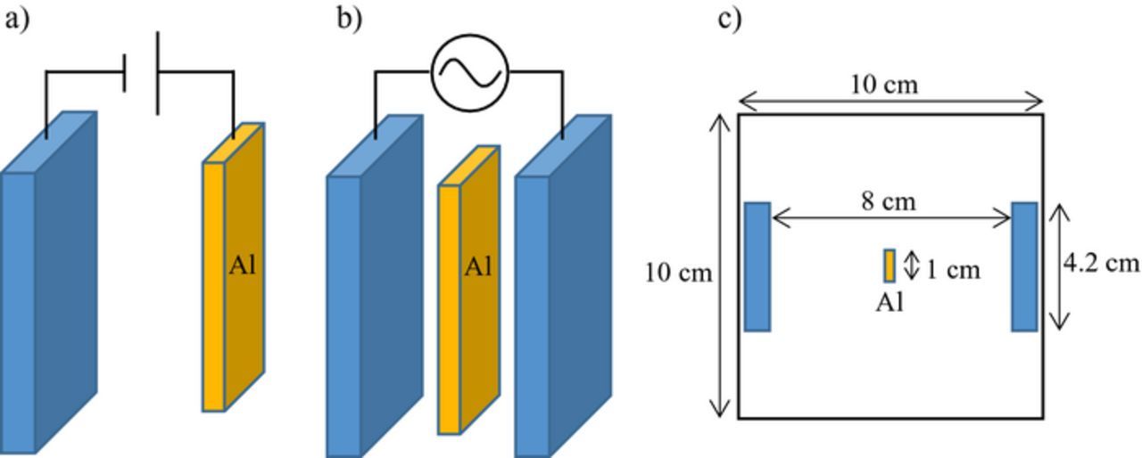
Figure 1. Schematic illustrations of (a) normal DC anodization and (b) bipolar anodization under an AC electric field. (c) Top view of the electrochemical cell used to perform AC-bipolar anodization.
Bipolar anodization of aluminum sheet under AC electric field
Figure 1b presents a schematic illustration of wireless bipolar anodization of aluminum via AC electrolysis. The cell consisted of two insoluble carbon electrodes with dimensions of 10 cm × 4.2 cm × 0.8 cm. The carbon electrode area exposed to the electrolyte was 9.5 cm × 4.2 cm × 0.8 cm. The distance between the outer carbon electrodes was 8 cm. An aluminum sheet was positioned at the center of the cell and surrounded by the electrolyte, as shown in Fig. 1c. The specimens were set in the electrolyte by a hanging on a wire in this study. No special operating system such as a diaphragm is used. We adopted a rectangular waveform with a designated frequency of 10, 50, 100, 150, 200, or 700 Hz. The AC voltage represents the maximum applied potential difference of the rectangular waveform. AC electrolysis was conducted in 8 mmol dm−3 oxalic acid at 20°C and 60 V using an AC power supply (Takasago, AA2000XG2). The changes in current transient during AC-bipolar anodization were measured using a digital multimeter with a data acquisition system (Iwatsu Electric Co., Ltd., VOAC7523H). Here the current represents the root mean square value (i.e., RMS).
Although sulfuric acid is known to be the most popular electrolyte for anodization, we changed the type of electrolyte from sulfuric acid to oxalic acid for AC-bipolar anodization. When sulfuric acid is used for AC anodization, sulfur and sulfur compounds are deposited in the pores of films because of the reduction of sulfuric acid during AC anodization.14,15 To avoid deposition of such sulfur compounds, it was desired to change the electrolyte. In addition, oxalic acid has the advantage that the range of anodization conditions for AC-bipolar anodization can be extended because the appropriate applied potential difference for anodization in oxalic acid is higher than that of sulfuric acid. Further details of the technique and conditions for bipolar anodization under an AC electric field were previously described.13
AC-bipolar anodization of aluminum balls
Aluminum balls (99.5% purity) with diameters of 3 mm (Taiyokokyujikuuke Co., Ltd.) were used in this study. For AC-bipolar anodization, the aluminum balls were placed into and agitated inside a perforated bag (made from polyethylene) while immersed in the electrolyte. The AC electrolysis conditions were the same as those in Sec. Bipolar anodization of aluminum sheet under AC electric field.
Characterization
Structural characterization
The nano-porous structures of the alumina films were evaluated using FE-SEM (JEOL JSM-6701F). The specimens were cut into small pieces and coated with a layer of Pt–Pd before the SEM examination.
Spectrophotometric method
After AC electrolysis, the specimens were mainly stained with a blue dye (TAC BLUE-BRL, 5 g dm−3, Okuno Chemical Industries Co., Ltd.) at 60°C for 10 min to evaluate the thickness and uniformity of the formed films. UV–Vis reflectance spectra were measured using a spectrophotometer equipped with an integrating sphere (KONICA MINOLTA, CM-5). For reflectance measurement of specimens, a target mask with an aperture of 5 mm diameter was used to select the measurement area. The colors were evaluated from the reflectance spectra in the CIE1976L*a*b* color space standardized by Commission Internationale de l'Eclairage. The CIE L*a*b* color space was determined according to DIN 5033, 2° Observer, Illuminant D65.
Results and Discussion
Film thickness
Figure 2a presents the current–time curve for DC anodization in 3 mol dm−3 sulfuric acid. The current density was calculated for the apparent surface area of the aluminum electrode acting as an anode. The current density was stable and approximately 60 A m−2 during DC anodization for 60 min, which suggests that the film thickness increased at a constant rate depending on the charge.
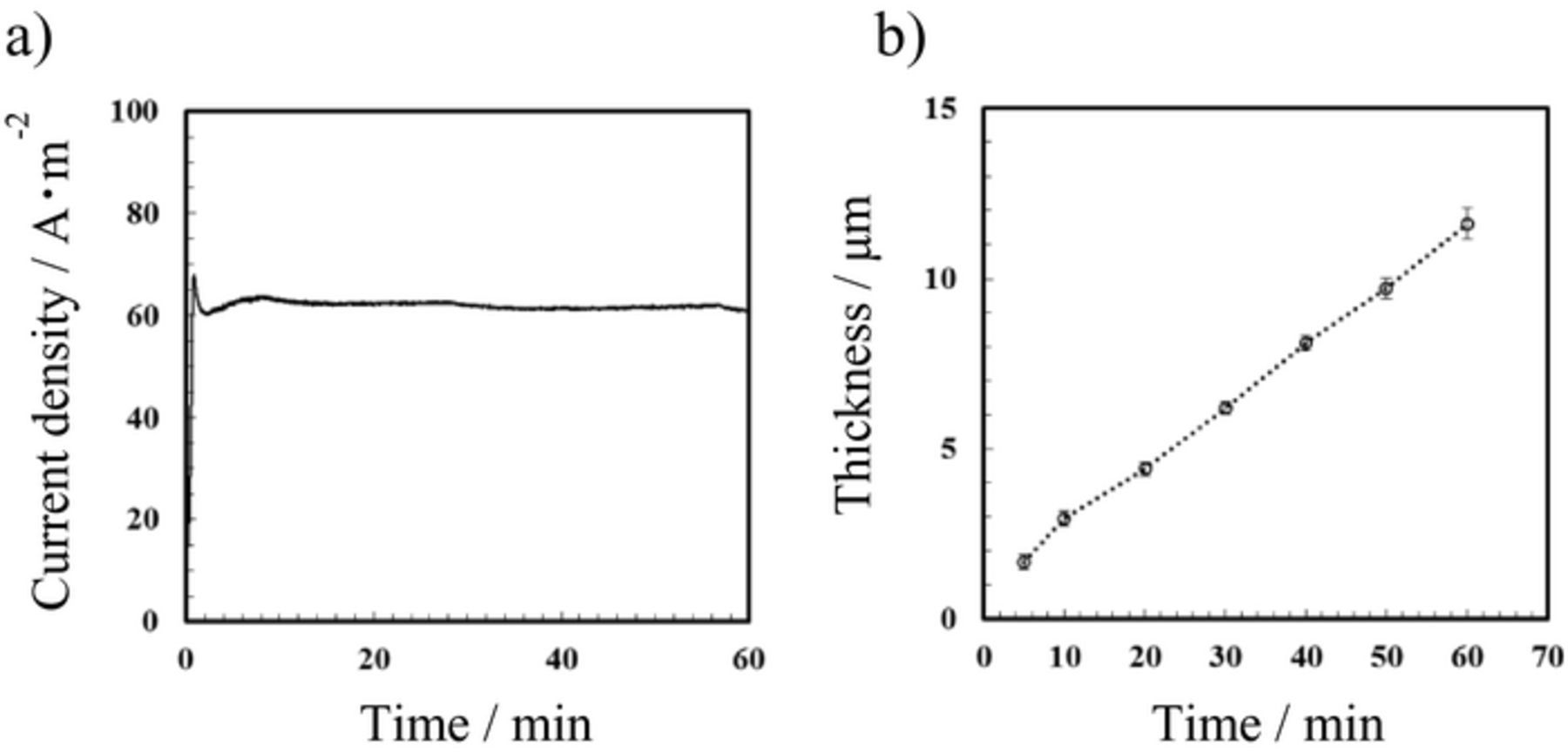
Figure 2. (a) Current density–time curve for DC anodization of aluminum and (b) relationship between film thickness and anodization time. Anodization was conducted in 3 mol dm−3 sulfuric acid at 20°C and 20 V.
Figure 2b shows the relationship between the film thickness and anodization time. The film thickness was directly measured using cross-sectional SEM. For DC anodization, the thickness of the oxide film is well known to be determined predominantly by the charge delivered. If the current density is almost constant during anodization at a constant applied potential difference, the charge delivered is determined by the anodization time. In the present case, the relationship between the film thickness and anodization time was approximately linear because of the stable DC anodization under almost constant current density. After anodization for 60 min, the film thickness was approximately 12 μm; the growth rate of the anodic alumina film was estimated to be approximately 3.3 nm s−1.
Figure 3 presents digital photos of the dyed specimens (1 cm × 5 cm), which were prepared by DC anodization with different anodization times followed by dyeing in blue dye. To confirm the effect of film thickness on the color tone of the specimens colored with the blue dye, the dyeing was conducted in the same bath at 60°C for 10 min in all the cases. The color tone of the anodized specimens changed from pale blue to a deeper blue with increasing anodization time. The pale color was attributed to interference of light reflecting from the top surface of the films and the interface of the alumina film as well as the underlying aluminum. The anodized specimens with relatively thin oxide films exhibited pale blue coloration compared with the deep blue color for thicker oxide films, which were prepared using longer anodizing times. This result clearly indicates that a thicker porous oxide film can be colored deep blue depending on the amount of dye absorbed into the pores.
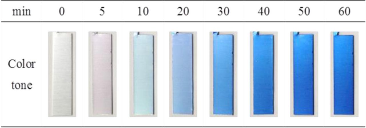
Figure 3. Digital photograph of aluminum sheets after DC anodization for different anodization times and subsequent dyeing. The anodization conditions were the same as those in Fig. 2.
UV–Vis reflection spectra of the dyed specimens are presented in Fig. 4a. The pretreated aluminum substrate exhibited a relatively high reflectance of 60–70% from UV to visible regions. Multiple oscillations with peaks and valleys are observed in the reflectance spectra of the specimens anodized for 5 and 10 min because the films were thinner. In general, the number of oscillations resulting from the interference was large for the thicker films and increased with increasing film thickness. Similar color properties of anodic oxide films on aluminum have been previously reported by several authors.16–20 When the film thickness reached 5 μm (i.e., anodization time of 20 min), it was difficult to detect the interference color. In addition, the reflectance at approximately 600 nm markedly decreased, whereas that at approximately 450 nm retained a high value of over 40%. These results indicate that the blue color became darker with increasing film thickness.
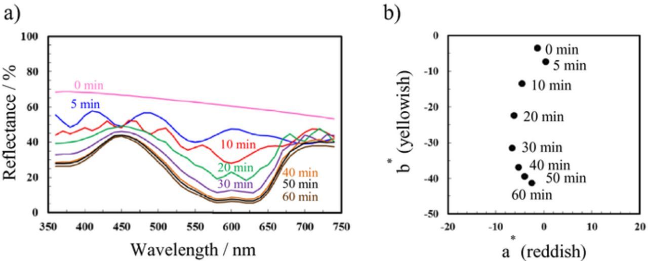
Figure 4. (a) UV–Vis reflectance spectra and (b) CIEL*a*b* color coordinates of aluminum specimens after DC anodization for different anodization times and subsequent dyeing.
Figure 4b presents the color coordinates in the CIE L*a*b* color space. Here, the a* and b* axes represent the red/green and yellow/blue components, respectively. For the a* axis, positive values indicate red, whereas negative values indicate green. For the b* axis, positive values indicate yellow, whereas negative values indicate blue. As observed in Fig. 4b, thicker oxide films formed after longer anodizing times had negative b* values. For the specimen anodized for 60 min, the b* value was approximately −40; this specimen had the deepest blue color of all the specimens. This tendency agrees well with the variation of color tone of the dyed specimens in Fig. 3. Therefore, the film thickness can be indirectly estimated by the color tone of the dyed specimens.
AC-bipolar anodization of aluminum sheet
In conventional anodization processes based on DC or AC electrolysis, a direct electrical connection between the aluminum object and outer electrode is essential for completing the electrical circuit. In the present study, the effects of an external field on the film formation on unconnected aluminum via AC electrolysis were investigated. Figure 5 presents a typical current–time curve for AC electrolysis of the unconnected aluminum sheet. The current density was calculated for the carbon electrode area exposed to the electrolyte (98.36 cm2) without accounting for the exposed aluminum surface area (10 cm2).
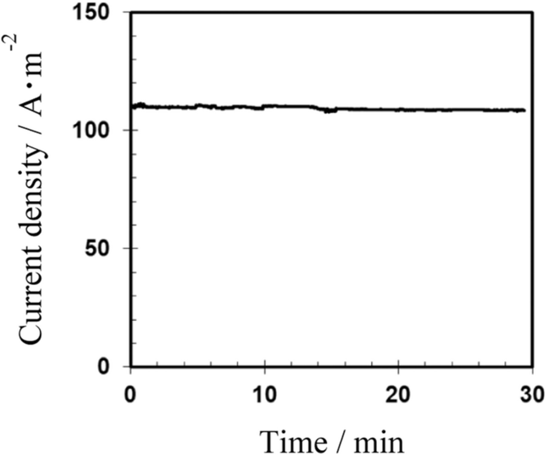
Figure 5. Change in AC current density with reaction time. The AC current density was measured for AC-bipolar anodization in 8 mmol dm−3 oxalic acid at 20°C and 60 V at a frequency of 150 Hz.
For AC electrolysis in 8 mmol dm−3 oxalic acid at 20°C, 60 V, and 150 Hz, which were the previously defined base conditions,13 the current density was approximately stable at 110 A m−2. This finding suggests that the electrochemical reaction proceeded at a constant rate depending on the charge (i.e., the current density). In our previous study, changing the frequency had little effect on the current density during AC electrolysis.13 The effects of temperature and applied potential difference on current density were also previously reported.13
In the present study, we also investigated the effect of frequency on the formation of porous alumina films using AC-bipolar anodization. Figure 6 shows the appearance of the specimen surfaces (1 cm × 5 cm) after AC-bipolar anodization and subsequent dyeing for comparison with those after DC anodization in Fig. 3. When AC electric field was applied to the outer electrodes, oxide film formation occurred on both sides of the aluminum.
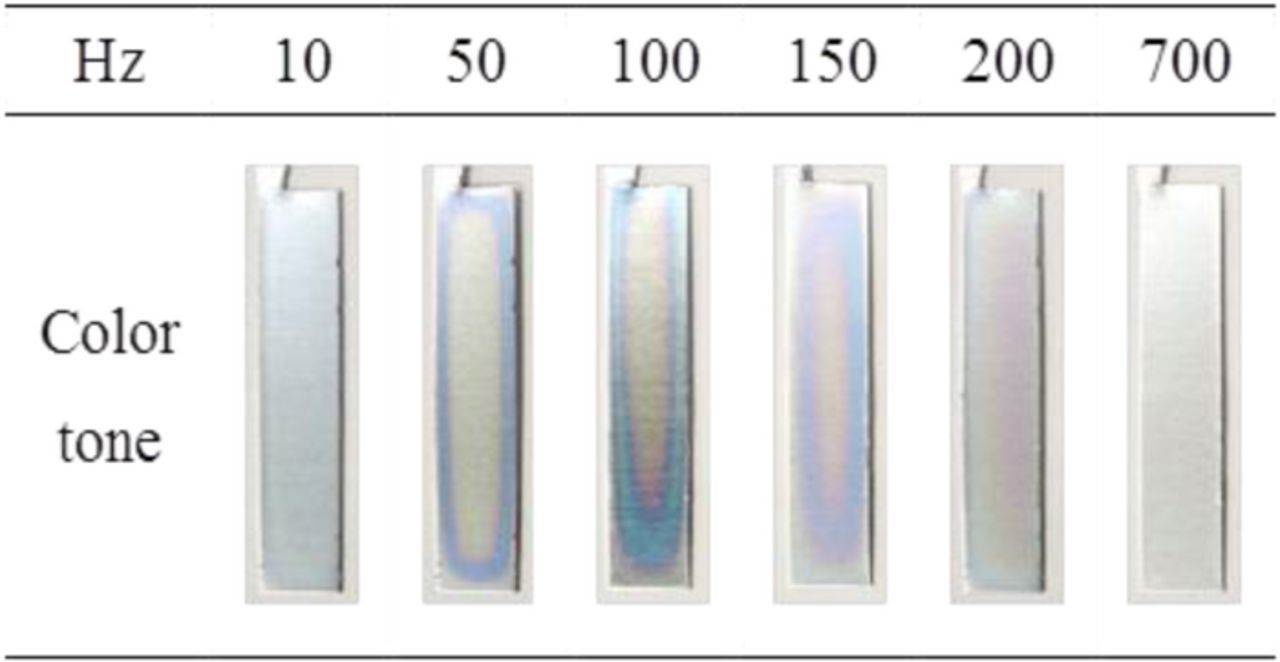
Figure 6. Digital photograph of aluminum sheets after AC-bipolar anodization for different frequencies and subsequent dyeing. AC-bipolar anodization was conducted in 8 mmol dm−3 oxalic acid at 20°C for 30 min at 60 V.
AC electrolysis was conducted in 8 mmol dm−3 oxalic acid at 20°C and 60 V for 30 min at various frequencies from 10 to 700 Hz. The current densities for the specimens treated at different frequencies were the almost same values (100–110 A m−2). Although the same output potential difference of 60 V was applied, the degree of dyeing differed distinctly; the thicknesses of the obtained films were thought to be different, causing these dyeing differences. The specimens treated at 100 and 150 Hz were relatively deep blue in color compared with the specimens treated at other frequencies. However, the blue coloration was not even over the entire surface of the aluminum bipolar electrode. These varying color tones indicate that the thickness of the formed films was not uniform. The heterogeneity of the color tone was observed on both sides of the aluminum.
Yang et al. studied the structural colors of anodic porous alumina films prepared using a carbon ball as a point cathode electrode for normal DC anodization and reported that the gradient of the film thickness was caused by the symmetrical distribution of current density on the aluminum anode.21 Even in this study, although the current distribution could not be measured on the aluminum bipolar electrode, the blue coloration indicates that the film thickness was non-uniform; the current density might have non-uniformly varied outward from the center of the aluminum specimen. Because the movement of the electric charge periodically reverses direction between the positive and negative, ion transport under an AC electric field is much more complicated than in DC. It may be necessary to consider forces such as electroosmosis and dielectrophoresis.22,23
The reflectance curves of the aluminum treated at frequencies ranging from 10 to 700 Hz are presented in Fig. 7a. AC electrolysis was conducted for 30 min in all the cases. The reflectance spectra were collected at a relatively dark blue part of the dyed specimens using a target mask. The reflectance of the aluminum specimens treated at 10, 50, and 200 Hz had relatively high values of 50–60 at a wavelength of approximately 400 nm. The color tone of these specimens was pale purple. For the aluminum specimens treated at 100 and 150 Hz, the reflectance at 580–640 nm markedly decreased, whereas the reflectance at 450–480 nm remained high (over 50%). The reflectance minimum of the aluminum treated at 100 Hz slightly shifted to longer wavelength compared with that of the specimen treated at 150 Hz. The spectral changes of the specimens treated at 100 and 150 Hz indicate that the blue or blue–green coloration became darker. However, the aluminum treated at 700 Hz exhibited a high reflectance over 80% from UV to visible regions. At this frequency, film formation was thought to be minimal or non-existent. As indicated by the CIE L*a*b* color coordinates of the dyed specimens in Fig. 7b, the aluminum treated at 150 Hz was relatively deep blue in color; a thicker oxide film could be formed at 150 Hz even for the same reaction time of 30 min.
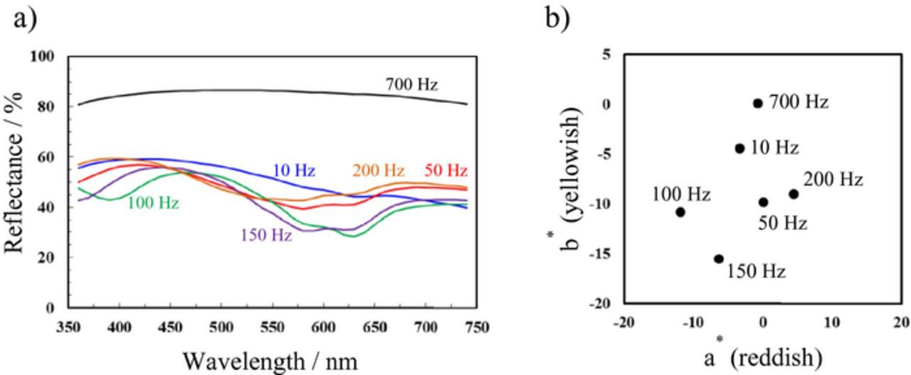
Figure 7. (a) UV–Vis reflectance spectra and (b) CIEL*a*b* color coordinates of aluminum specimens after AC-bipolar anodization and subsequent dyeing.
Figure 8 shows the effect of frequency on the surface morphology of the porous alumina films. At a lower frequency of 10 Hz and a higher frequency of 700 Hz, the pore diameter of the obtained porous oxide films was approximately 10 nm and relatively large. At a higher frequency of 700 Hz, the thickness of alumina film was several tens of nanometers. However, in the middle range of 50–200 Hz, porous alumina films with relatively small pores were formed. The pore diameter was less than 5 nm, as observed in Figs. 8b–8e. The chemical dissolution and alkalization of the solution due to the hydrogen evolution, associated with cathodic current, might affect the pore diameter of the formed films.24
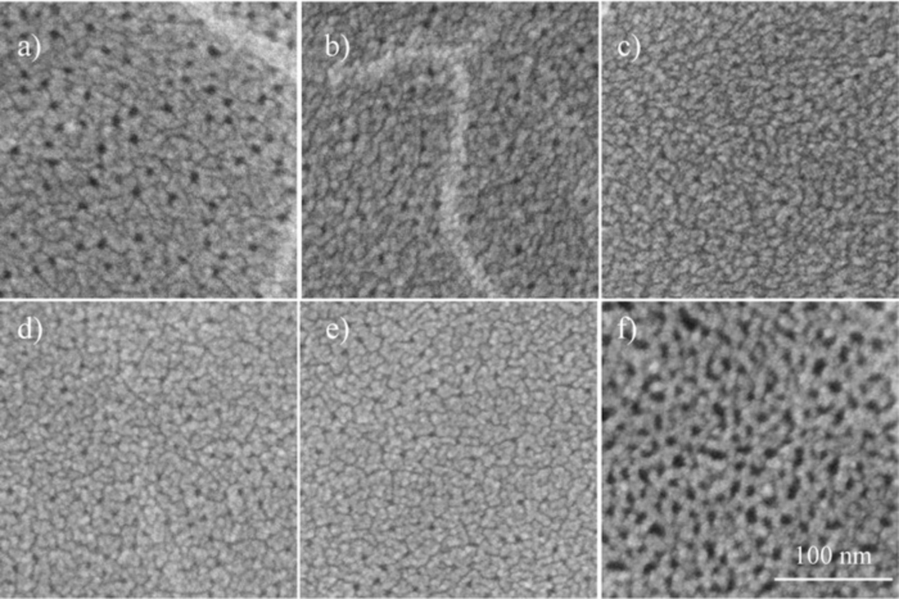
Figure 8. SEM images of surface of aluminum specimens after AC-bipolar anodization in 8 mmol dm−3 oxalic acid at 20°C and 60 V for 30 min at (a) 10, (b) 50, (c) 100, (d) 150, (e) 200, and (f) 700 Hz.
Figure 9 shows cross sectional SEM images of the alumina films formed by AC-bipolar anodization at 60 V. SEM images of the films formed by conventional AC anodization at 5 V and 60 V are displayed for comparison.25 These images indicate that the dimensions of porous alumina (e.g., film thickness, interpore distance, and pore diameter) treated at 60 V using AC-bipolar anodization without a direct electrical connection were roughly the same as those formed at 5 V using conventional AC anodization with a direct connection. It corresponds to the potential distribution on the aluminum used as a bipolar electrode, which was located between the driving electrodes. If an applied potential difference between the driving electrodes is big enough, redox reactions can be carried out on the unconnected aluminum electrode. When AC anodization was conducted at 60 V, laminated films with discontinuous pores were formed, as shown in Figs. 9c and 9f, the details of which were reported in our previous paper.25 Although AC electrolysis was conducted under the same applied potential difference of 60 V, the structure of the obtained films was distinctly different due to the difference in the potential distribution established between the electrodes.
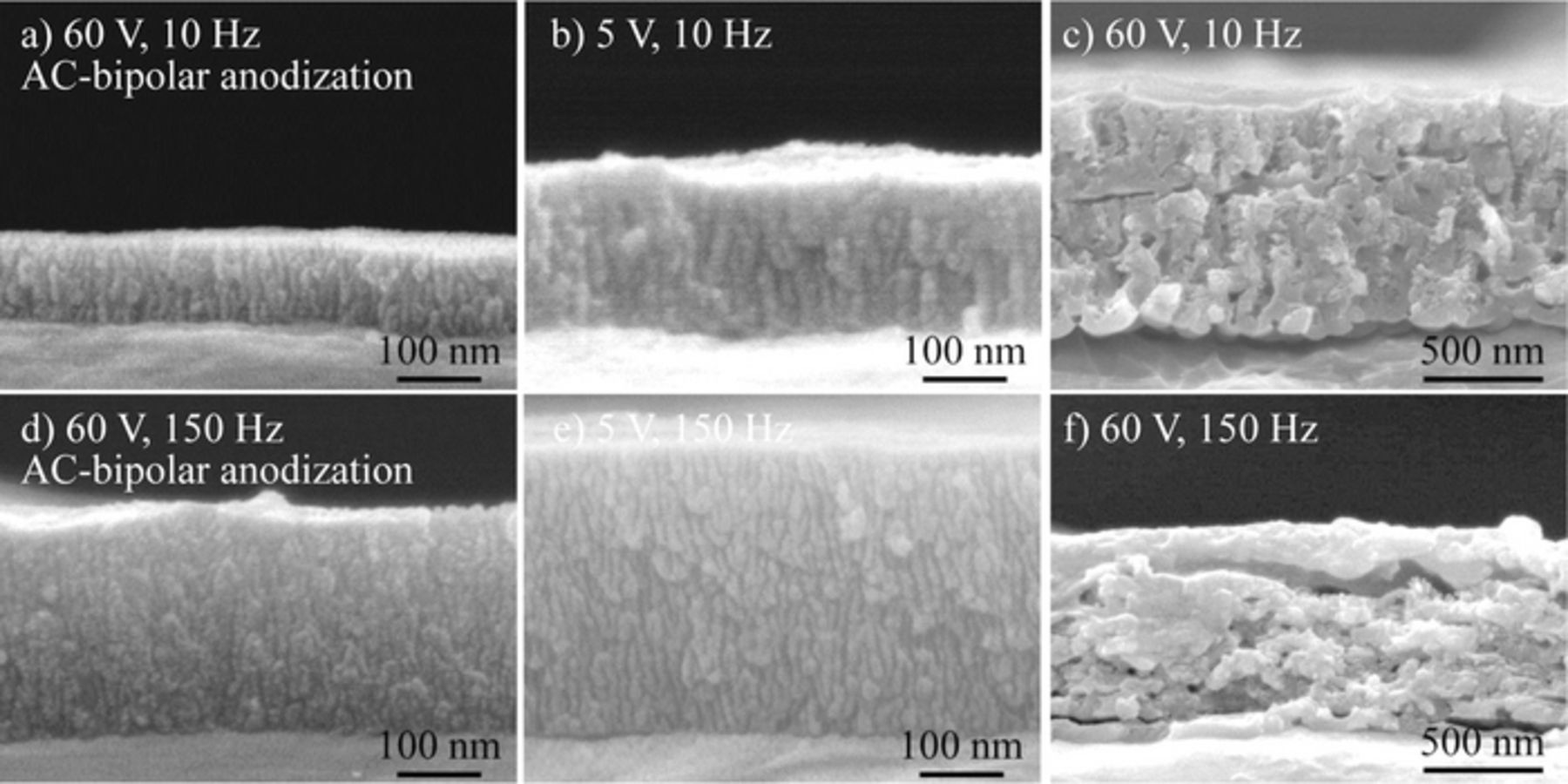
Figure 9. Cross-sectional SEM images of porous alumina films formed at different applied potential differences and frequencies by (a, d) AC-bipolar anodization and (b, c, e, f) AC anodization in 8 mmol dm−3 oxalic acid at 20°C for 30 min.
The flow of current and the potential distribution on the aluminum bipolar electrode seem to be similar to those of stray current–induced polarization.26 When a current is applied through an electrolyte, ions move toward the oppositely charged electrode. At that moment, a conductive material with delocalized electrical charges is electrostatically polarized. This electrostatic separation of charges induces a polarization, which enables redox reactions on the bipolar electrode. If the resistance of the aluminum electrode and the polarization resistance at the two surfaces is less than the resistance of the electrolyte, the current will flow through the unconnected aluminum electrode. Although it is difficult to provide a clear explanation of the potential distribution on a unconnected aluminum electrode at present, further studies on the dependency of applied potential difference for the dimensions of porous alumina films would facilitate the understanding of the mechanism of film growth during AC-bipolar anodization.
The relationship between film thickness and frequency is presented in Fig. 10. The film thickness was evaluated directly from SEM images for the undyed specimens. This result was the average of ten measurements in different areas except for thin part of the film at edges. Plots of the films formed by conventional AC anodization at 5 V are displayed for comparison.25 The films formed at frequencies in the range from 50 to 150 Hz were thicker than those formed at other frequencies even in the same reaction time of 30 min in both cases. After AC-bipolar anodization for 30 min at 150 Hz, the thickness of the porous alumina film was approximately 270 nm. This result for AC-bipolar anodization agrees well with the variation of color tone of the dyed specimens shown in Figs. 6 and 7. Moreover, an important point to emphasize is that the dependence of frequency on film thickness was almost in agreement with the tendency observed for conventional AC anodization. This finding suggests that the film formation behavior for AC-bipolar anodization was quite similar to that of conventional AC anodization. In fact, even if an electrical connection is indirect ("wireless treatment"), the anodic reaction (i.e., anodic film formation) proceeds by switching polarity during AC electrolysis.
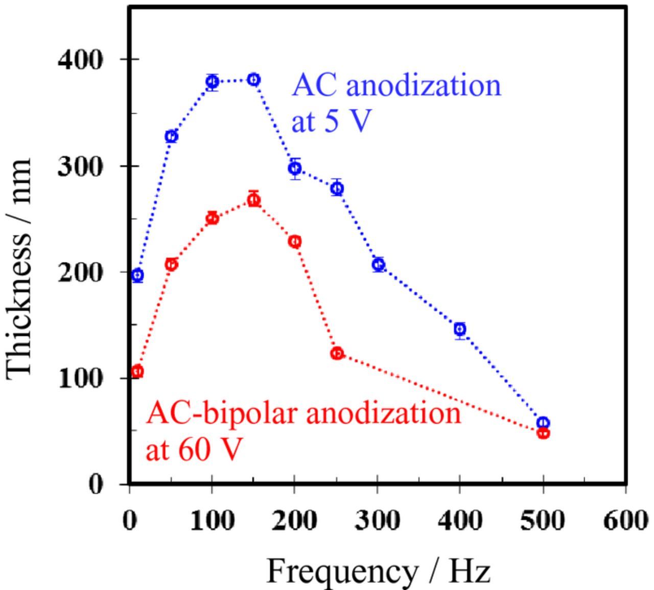
Figure 10. Relationship between film thickness and frequency. AC-bipolar anodization and AC anodization were conducted in 8 mmol dm−3 oxalic acid at 60 V and 5 V, respectively.
For AC-bipolar anodization presented in this study, even though the same output potential difference of 60 V was applied to the outer carbon electrodes used as driving electrodes in all the cases, the dimensions of the porous structure varied based on the frequency, as shown in Figs. 8–10. As with conventional AC anodization with a direct connection,25 balance between the anodic current (which contributes to film formation) and the cathodic current (which contributes to hydrogen evolution) is speculated to be an important factor affecting the film structure. In the range from 50 to 150 Hz, the balance between the anodic reaction ("film formation") and the cathodic reaction ("hydrogen evolution") might be adequate for efficient film formation. At low frequency of 10 Hz, the low film thickness is thought to be due to low effective current density as well as conventional AC anodization.25 On the other hand, it is possible that the efficiency of oxide film formation decrease due to larger capacitive currents at high frequency of 700 Hz.24 The details of the relationship between current density and frequency for AC-bipolar anodization are presently not completely understood. For a more precise understanding of current response, further investigations by the oscilloscope measurement or electrochemical impedance spectroscopy are necessary.
In contrast to DC anodization, ion migration of the cations (e.g. Al3+) and the anions (e.g. O2−, OH−, and electrolyte-derived anions) under an AC electric field is complicated. For the growth of porous alumina films during AC-bipolar anodization, the transport number and mobility of electrolyte species should be considered. Attempts to clarify the effects of the composition and concentration of an electrolyte and waveform on the film structure of porous alumina under an AC electric field are currently underway in our laboratory.
Simultaneous AC-bipolar anodization of aluminum balls
To expand the range of applications of the anodization technique, the development of surface treatments that do not depend on the sizes and shapes of the products is strongly desired. An important advantage of AC-bipolar anodization presented here is that it enables the formation of a porous alumina film even on a surface with a large number of small components, including small balls. Because such small balls cannot be uniformly oxidized using conventional anodization, which requires a direct electrical connection, a surface treatment for small aluminum components has not yet been established.
Figure 11 presents a photograph of aluminum balls with diameters of 3 mm after AC-bipolar anodization and subsequent dyeing. AC-bipolar anodization was conducted for 240 min under the base conditions used in our previous study.13 The treated aluminum balls were then immersed in blue, red, yellow, and black dyes. The dyes were absorbed by the porous alumina films over the entire surface of the aluminum balls; no undyed portion was detected. This result indicates that the porous alumina films were uniformly and simultaneously formed on numerous aluminum balls.
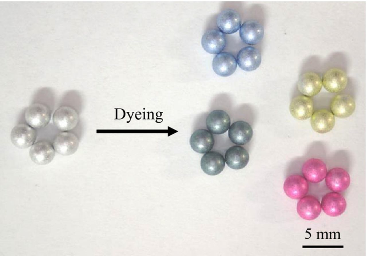
Figure 11. Digital photograph of aluminum balls after AC-bipolar anodization and subsequent dyeing. AC-bipolar anodization was conducted in 8 mmol dm−3 oxalic acid at 20°C for 240 min at 60 V.
Although there is room for further investigations, AC-bipolar anodization is considered to be a valid method for the fabrication of symmetrical objects without electrical connection. Using the indirect-oxidation-based surface treatment, aluminum components with a wide variety of sizes and shapes can be oxidized with high throughput at a low cost. We believe that this method based on a wireless process can introduce new possibilities for electrochemical surface treatment of various conductive materials, including semiconductors and metals other than aluminum.
Conclusions
We investigated the effect of an external electric field on oxide film formation on unconnected aluminum electrodes. When AC electric fields were applied, symmetrical films were simultaneously formed on both sides of the aluminum sheet bipolar electrode. Notably, the aluminum surfaces were continually exposed to the anodic and cathodic reaction by switching polarity during AC electrolysis. The films formed at frequencies in the range from 50 to 150 Hz were thicker than those formed at other frequencies even in the same reaction time. Moreover, an important point to emphasize is that the dependence of frequency on film thickness was almost in agreement with the tendency observed for conventional AC anodization.
Acknowledgments
This work was supported by the Light Metal Education Foundation of Japan and by a Grant-in-Aid for Challenging Exploratory Research [grant number 17K18994] from the Japan Society for the Promotion of Science.
ORCID
Hidetaka Asoh 0000-0003-0722-9994