Abstract
We report the use of cubic palladium nanoparticles (PdNPs) for the catalytic oxidation of hydrazine for use in a hybrid self-powered N2H4 sensor. Multiwalled carbon nanotube electrodes were prepared and functionalized with PdNPs by drop casting, confining the colloidal suspension of nanoparticles into the 3D-carbon nanotube matrix support. Electron microscopy and electrochemical characterization experiments were performed and confirmed the presence, uniform distribution, and accessibility of the metallic particles. Cubic PdNPs with an average diameter of 22.5 nm were investigated for their catalytic hydrazine oxidation capacities at varying hydrazine concentrations. Application of the PdNPs for electrochemical detection of hydrazine was demonstrated using a hybrid fuel cell setup with the PdNPs-based electrode as the anode and a bilirubin oxidase bioelectrode as the oxygen-reducing cathode. The self-powered hybrid sensor exhibits linear hydrazine detection from 0.02 to 4.00 mmol L−1 and a sensitivity of 53 ± 3 mW cm−2 mmol−1 L. When using the air-breathing cathode setup, the fuel cell could deliver a maximal current and power output of 1.23 ± 0.08 mA cm−2 and 267 ± 10 μW cm−2 respectively. PdNPs supported on carbon nanotube electrodes are thus promising catalytic materials for self-powered sensing and hybrid fuel cell applications via consumption of environmental contaminants.
Export citation and abstract BibTeX RIS

This is an open access article distributed under the terms of the Creative Commons Attribution 4.0 License (CC BY, http://creativecommons.org/licenses/by/4.0/), which permits unrestricted reuse of the work in any medium, provided the original work is properly cited.
Hydrazine, N2H4, is extensively used commercially for the production of agricultural herbicides and pesticides, as a rocket propellant in the aerospace industry, as the refining agent for precious ores recovery, and as a corrosion inhibitor (oxygen scavenger) in water boiler rooms.1,2 The use of N2H4 as a fuel has attracted huge interest since the 1970s largely due its high solubility, rapid kinetics and low oxidation potential which enable large current densities not possible with other fuels such as hydrogen and ethanol.3 The theoretical electromotive force for a N2H4/O2 fuel cell is relatively large with a value of 1.56 V compared to other fuel/oxidant couples (1.23 V for H2/O2, 1.20 V for glucose/O2 and 1.15 V for ethanol/O2 systems) and therefore desirable for increasing overall performances.4–6 N2H4 is also a "carbon-free" reducing agent due to its efficient conversion into N2 gas and water unlike more traditional fuels which release CO2 during their oxidation process. Hydrazine can also be stored in liquid form and will not participate in increasing greenhouse gas levels as is the case for other fuels such as hydrogen gas.
As a result of widespread industrial use, hydrazine and its derivatives are frequently found in our environment and this poses health risks. Hydrazine is a documented toxic environmental contaminant and is known for its potential human carcinogenic and mutagenic effects.7,8 Even acute poisoning can result in adverse health conditions ranging from dizziness to damage of the central nervous system.8 Since large volumes of hydrazine are consumed on a daily basis and this consumption will likely increase with time, there is a great need to develop methods of detecting and remediating hydrazine in the environment. Current methods of dealing with high levels of hydrazine in the environment include chemical treatment with oxidizers such as sodium/calcium hypochlorite (bleach). Thermal or chemical methods typically give incomplete oxidation and may create more hazardous conditions than before the treatment.9 The development of disposal techniques which completely convert hydrazine fuel or environmental solutions to non-toxic compounds is therefore highly desirable and only a few (bio)chemical approaches exist.10,11 However, these techniques only intend to phase out hydrazine from fuel or contaminated solutions without taking advantage of its high energy density.
Several electrochemical systems have now been developed for detection and/or electrocatalytic oxidation of hydrazine in aqueous solutions. However, the electrochemical response at unmodified electrodes is hindered by slow electron transfer kinetics and a very large oxidation overpotential requirement, leading to poor sensitivity and reproducibility. A range of electrodes have been developed to address these limitations including chemically-modified electrodes with metal complexes as efficient electrocatalysts. More recently, the use of composite carbon electrodes with metal particles and nanoparticles have been developed as effective composite catalytic electrodes.12–17 Palladium nanoparticles are currently of high interest as electrocatalysts for direct hydrazine oxidation owing to their rate-enhancing electronic properties.18 However, despite the attraction of such electrocatalysts for hydrazine oxidation for sensing or energy production purposes, to the authors' best knowledge, no reports exist on their integration into hybrid biofuel cell systems. Furthermore, such hybrid systems could be developed into self-powered systems, a concept first reported by Katz and coworkers, where the fuel cell output is used as the sensor signal.19
In this work, we aim to demonstrate that CNT-supported PdNPs catalysts can be used for the consumption of aqueous hydrazine as a possible method of environmental remediation whilst, at the same time, generating clean electrical power and/or sensing the concentration of hydrazine present. Initial investigations were performed to optimize PdNPs loadings on MWCNT surfaces. Since hydrazine is known to scavenge dissolved oxygen, bilirubin oxidase (BOx) biocathodes made from gas diffusion layer (GDL) electrodes were utilized for construction of a hybrid hydrazine/O2 fuel cell and self-powered sensor. This fuel cell configuration was adapted to overcome low O2 concentration in aqueous electrolyte solution to improve overall catalytic performances.
Materials and Methods
Chemicals and materials
Polyvinylpyrrolidone (PVP, MW ∼ 55,000 g mol−1), L-ascorbic acid, potassium bromide, potassium tetrachloropalladate(II), 1-pyrenemethylamine hydrochloride (PMA), 5,5'-dithio-bis(2-nitrobenzoic acid) (DTNB), N-hydroxysuccinimide (NHS), hydrazine solution (N2H4; 35 wt% in H2O) and 1-methyl-2-pyrrolidone (NMP), disodium citrate, and sodium phosphate were obtained from Sigma Aldrich and used as received. N-(3-Dimethylaminopropyl)-N'-ethylcarbodiimide hydrochloride (EDC) was purchased from Fluka. Bilirubin oxidase (BOx) from Myrothecium verrucaria (E.C. 1.3.3.5) was purchased from Sigma Aldrich. Reagent grade acetonitrile (CH3CN) was received from VWR Chemicals Commercial grade thin multi-walled carbon nanotubes (MWCNTs) (NC3100, 9.5 nm diameter, 1.5 μm length, purity > 95%,) were obtained from Nanocyl (Belgium). Gas diffusion layers (GDL) were non-treated carbon cloth electrodes and were purchased from PAXITECH (France). Distilled deionized water (15 MΩ) was obtained from a PURELAB ELGA purification system. Oxygen and argon were purchased from Air Liquide (France).
Oxidizing electrode fabrication
The anodes used for N2H4 oxidation were made by layer-by-layer deposition of MWCNTs with cubic PdNPs. A 2.5 mg mL−1 MWCNT dispersion in NMP was prepared by 30 min sonication to achieve a homogeneous black suspension. The black suspension was deposited onto the glassy carbon electrode (GCE) to give an electrode disc with a geometric surface area of 0.126 or 0.196 cm2 for 10 or 20 μL droplet deposits, respectively, followed by deposition of various loadings of PdNPs (4 mg mL−1 in NMP). The load of PdNPs was adjusted by depositing different solution volumes onto the electrode surface. The distribution of the deposited cubic PdNPs on the MWCNT electrode surface was verified by scanning electron microscopy (SEM) with a QUANTA FEG 250 (FEI) without coating the substrates with metal. Secondary electron and backscattered electron detection modes were used to assess topography and chemical composition of the samples, respectively. The morphologies of the cubic PdNPs were previously characterized by transmission electron microscopy (TEM) using a JEM-1011 TEM transmission electron microscope operated at 100 kV. For the analysis, one aliquot of the dispersed samples in ethanol was deposited onto a 400-square mesh copper grid with carbon film and dried under vacuum.
Bioreducing electrode fabrication
MWCNT enzyme-modified electrodes were prepared from a 2.5 mg mL−1 suspension in NMP after 20 min sonication and vigorous shaking immediately before use. The black suspension was deposited onto the GCE to give an electrode disc with a geometric surface area of 0.196 cm2 for a 20 μL droplet. The solvent was then removed over several hours under vacuum. Next, the electrodes were incubated in a 10 mmol L−1 PMA solution in CH3CN for 1 h and thoroughly rinsed with CH3CN then deionized water. Subsequently, electrodes were left to incubate in a 4 mmol L−1 DTNB, 4 mmol L−1 NHS and 2 mmol L−1 EDC solution (0.2 mol L−1 phosphate buffer (PB), pH 7.0) for 5 h. The electrodes were rinsed with deionized water to remove any loosely bound species then soaked in McIlvaine buffer (pH 7.0). Modified-(DTNB-Pyr)/MWCNT electrodes were then incubated overnight at 4°C in 40 μL of BOx solution (2.5 mg mL−1) prepared in McIlvaine buffer (pH 7.0). Before testing, electrodes were thoroughly rinsed with deionized water and soaked in fresh McIlvaine buffer solution. For preparation of GDL-based air-breathing biocathodes for sensing, the same preparation methodology was applied as that used for GC electrodes. To ensure the biocathode was not the limiting electrode, three droplets of 20 μL each were deposited onto the GDL surface. The geometric surface area of the GDL-based biocathodes was SGDL = 0.378 cm2.
Electrochemistry
A Biologic VMP3 Multi Potentiostat controlled with EC-lab software was used to perform electrochemical experiments. A three-electrode setup was used for half-cell characterization comprising a glassy carbon electrode (Ø = 3 mm, ALS Co., Japan) as the working electrode, platinum wire as the counter electrode, and a saturated calomel electrode (SCE) as the reference electrode. Prior to modification, the GCE working electrodes were polished with a 2 μm diamond paste purchased from Presi (France), rinsed successively with deionized water, acetone, and ethanol, then left to sonicate for 5 min in ethanol. McIlvaine buffer solutions (pH range: 3 ≤ pH ≤ 9) were used as supporting electrolytes. All solutions for N2H4 oxidation experiments at the half-cell anode were purged with nitrogen gas and a nitrogen flow was maintained on top of the solution during analysis. All experiments were conducted at room temperature unless stated otherwise. Catalytic onset potentials were determined from the foot of the electrocatalytic wave.
Hybrid hydrazine sensor, removal and power system
The fuel cell/sensor set-up comprised of a rounded poly(methyl methacrylate) tube and a flat poly(methyl methacrylate) piece assembled over a rubber joint to form the fuel cell reservoir (see Figure S1). For the air-breathing cell, a 5 mm diameter hole was made into the flat piece to expose the BOx-modified air-breathing biocathode to air. The complete hybrid biofuel cell and sensor system consisted of a PdNPs/ MWCNT anode and a BOx/(DTNB-Pyr)/MWCNT biocathode or BOx/(DTNB-Pyr)/MWCNT/GDL biocathode. The distance between the electrodes was approximatively 1 cm. Oxygen flow was qualitatively maintained but not monitored to obtain reproducible steady state currents between different experiments. When the air-breathing GDL biocathode was used, no additional O2 was provided to the electrolyte. Testing was performed with a relatively slow scan rate of 2 mV s−1 using linear sweep voltammetry. All experiments were performed in a 5 mL volume of McIlvaine buffer (pH 7.0) solution.
Results and Discussion
Scanning electron microscopy characterization of PdNPs and PdNPs/MWCNT-based electrodes
The cubic PdNPs used here with average size of 22.5 ± 2.6 nm were synthesized and characterized as described in our recent work.20 Figure 1A shows a TEM micrograph and the corresponding correlated size distribution for the PdNPs, which confirms good dimension homogeneity and a high yield of cubic shapes. SEM imaging was subsequently performed to assess the presence and distribution of the PdNPs on the MWCNT-based electrodes prepared by deposition from the nanoparticle solution as described in the Experimental section. Figure 1B and 1C show SEM micrographs recorded at an unmodified MWCNT electrode and a PdNP-modified MWCNT electrode, respectively. A well dispersed and homogeneous three-dimensional CNT network is observed for the unmodified MWCNT electrodes. For the PdNPs-modified MWCNT electrodes, the CNT network was maintained and the appearance of bright spots associated with individual and aggregated nanoparticles were observed at high magnification. The relatively uniform distribution of bright spots was observed at multiple regions of the surface indicating an even coverage of PdNPs across the MWCNT electrode surface. The increased brightness observed across parts of the carbon nanotube network for the PdNP-modified MWCNT electrodes is attributed to polymeric material associated with the as-prepared nanoparticle solution. Overall, the electron microscopy analysis confirms the presence and good homogeneous distribution of PdNPs on the surface of the modified electrodes.
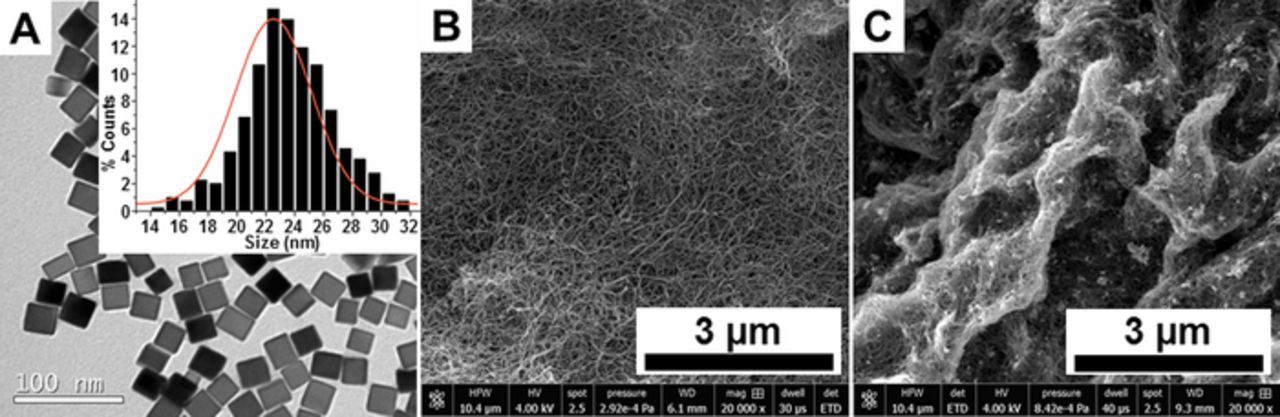
Figure 1. (A) TEM images of 22.5 nm cubic PdNPs synthesized in the presence of 11 mmol L−1 HCl and the correlated histogram of size distribution (inset). SEM images of (B) an unmodified MWCNT surface and (C) a MWCNT/cubic PdNPs surface. The images were recorded using a secondary electron detector (Everhart-Thornley; ETD) to visualize the in-depth details of the MWCNT deposit.
Electrochemical characterization of PdNPs/MWCNT-based electrodes
Figure 2A shows typical cyclic voltammograms (CVs) recorded at unmodified MWCNTs and PdNPs/MWCNT electrodes with cubic PdNPs (22.5 nm) in deaerated McIlvaine buffer (pH 7.0) solution. The CV for bare MWCNT electrodes did not present any faradaic signal when scanning in the range from −0.85 V to 0.3 V vs. SCE at 10 mv s−1. For the PdNP-modified MWCNT electrodes, the voltammograms in the same range reveal the appearance of electroactivity between −0.7 to −0.4 V. The redox peaks observed at negative potentials are ascribed to the characteristic peaks of hydrogen adsorption and desorption on palladium, as reported in different literature reports.21,22 Upon scanning of the PdNPs/MWCNT electrode at more positive potentials, a broad oxidation wave was observed with an onset potential of around 0.5 V and current maximum at 0.6 V, corresponding to hydroxide (PdOH) and oxide (PdO) formation on the Pd surface, as reported previously.21 After formation of the oxide, a new reduction peak appeared on the reverse sweep near 0.0 V, corresponding to palladium oxide reduction. The reduction peak currents were found to be linearly dependent on the scan rate, sustaining the presence of an adsorbed species on the MWCNT electrodes and, furthermore, confirming the good adhesion of the nanoparticles on the MWCNT surface (Figure 2B).
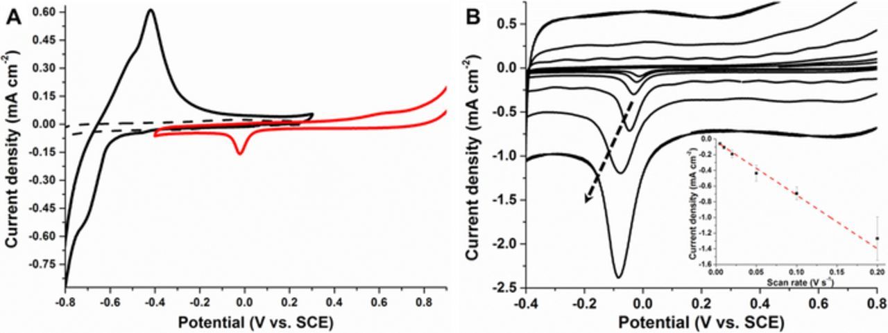
Figure 2. (A) Cyclic voltammograms recorded in the hydrogen evolution region at an unmodified MWCNT GC electrode (dashed line) and PdNPs/MWCNT-modified GC electrode (black solid line) in McIlvaine buffer solution (pH 7.0); (red solid line) cyclic voltammograms recorded at PdNPs/MWCNT-modified GC electrode in the PdO region. Voltammograms recorded (second scans shown) in deaerated solution at scan rate = 10 mVs−1. (B) Cyclic voltammograms of PdNPs/MWCNT-modified GC electrode recorded at different scan rate from 5 to 200 mV s−1 (the black arrow indicates increasing scan rates). Inset: Plot of cathodic peak current for PdO reduction versus the scan rate.
The hydrogen evolution region for MWCNT electrodes modified with cubic PdNPs was investigated in McIlvaine buffer over a pH range from 3.0 to 9.0. Figure 3 shows second scan CVs recorded in N2 saturated solution at different pHs. The oxidation peak potentials shifted in a linear manner toward more negative values with increasing pH, giving an average slope of −55 ± 2 mV per pH unit.
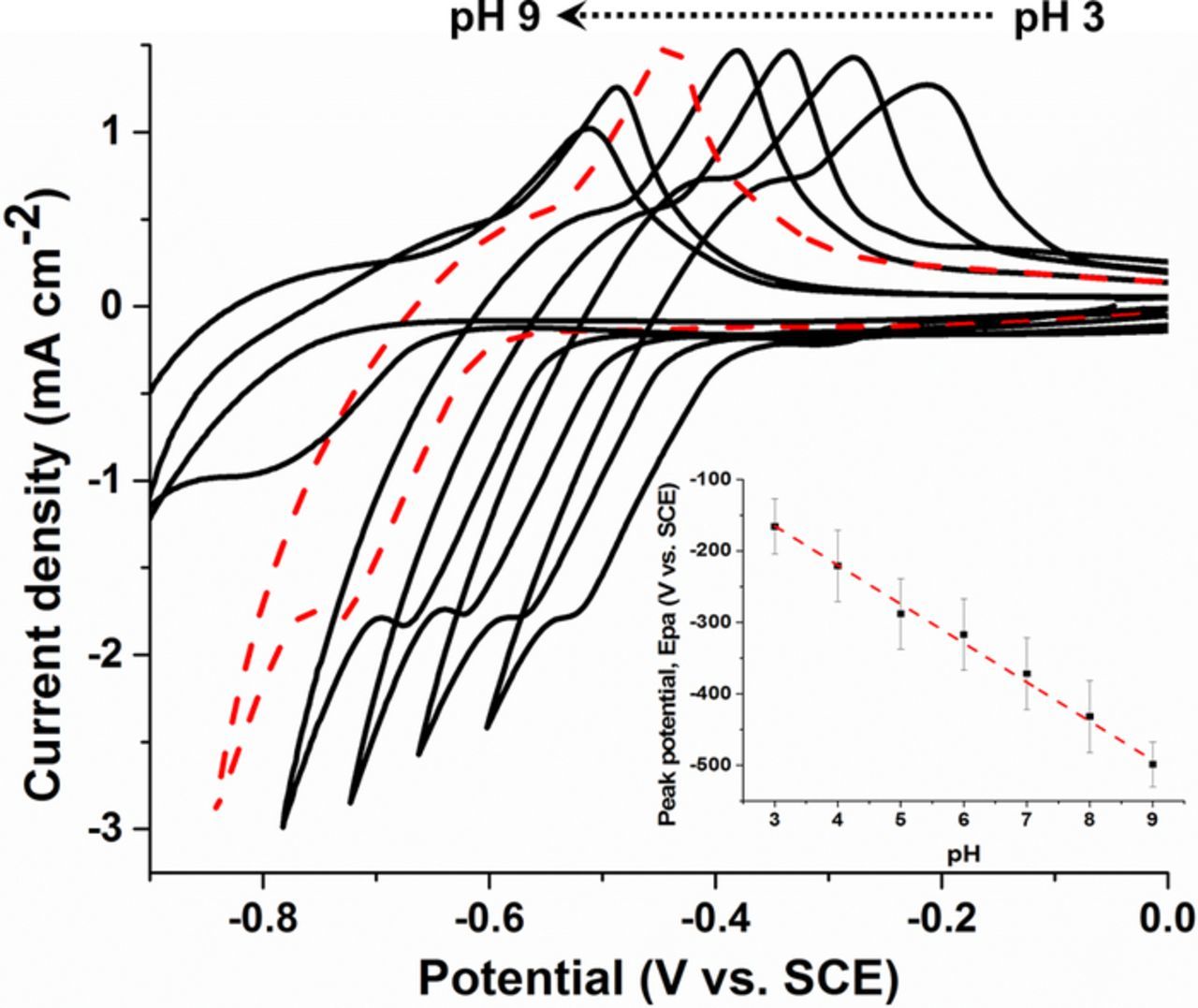
Figure 3. Representative cyclic voltammograms for PdNPs/MWCNT–modified GC electrodes under deaerated solution in McIlvaine buffer at different pH values (dashed line represents pH 7.0). (Inset) Corresponding plot of the anodic peak potential associated with hydrogen adsorption over the full pH range. Error bars represent one standard deviation from triplicate experiments. Voltammograms recorded (second scans shown) in deaerated solution at scan rate = 10 mVs−1.
In order to maximize the surface coverage of PdNPs we investigated the effect of PdNP loading on the MWCNT electrode by monitoring the increase in peak current corresponding to dihydrogen oxidation. Figure 4 depicts the anodic current peak height recorded at −0.45 V as a function of the volume of PdNPs drop-casted for MWCNT electrodes prepared from two different volumes of 2.5 mg mL−1. The palladium loading on the PdNPs/MWCNT-GC modified electrodes investigated therefore varied. The plots in Figure 4 reveal that the dihydrogen oxidation current obtained for electrodes prepared by addition of between 1–5 μL of PdNPs solution (4 mg mL−1) reaches a limiting current after addition of 1 μL of nanoparticle solution for the MWCNT electrodes prepared with a smaller CNT solution volume (10 μL) of CNTs (ie 10% vPdNPs/vCNT). However, for the MWCNT electrodes prepared with a larger volume (20 μL) of CNTs (ie 12.5% vPdNPs/vCNT), larger oxidation currents were obtained after addition of between 2.5 to 5 μL of nanoparticle solution (4 mg mL−1), with a limiting current after addition of 2.5 μL of solution. These experiments clearly show that that the amount of hydrogen oxidation current and therefore PdNP loading can be controlled by finely adjusting the volumes of PdNP and CNT solutions used during electrode fabrication. Based on these results, nanocomposite PdNP electrodes with high PdNPs loadings were prepared for electrocatalytic oxidation of hydrazine. The electrodes used to study hydrazine oxidation were prepared using 10% vPdNPs/vCNT and 12.5% vPdNPs/vCNT ratios.
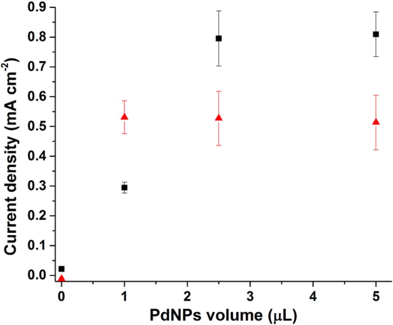
Figure 4. Anodic current peak height recorded at −0.45 V as a function of the PdNPs volume used for surface modification for (▪) 20 μL MWCNT electrodes and (▴) 10 μL MWCNT electrodes under deaerated solution in McIlvaine buffer (pH 7.0) at scan rate = 10 mVs−1. Error bars represent one standard deviation from triplicate experiments.
PdNPs-based MWCNT electrodes for electrocatalytic N2H4 oxidation
Since we previously showed that oxygen can be effectively reduced by PdNPs (22.5 nm diameter) at potentials below 0.25 V vs. SCE in aqueous solution,20 we investigated these PdNPs for the oxidation of hydrazine on MWNT-modified electrodes at neutral pH and in deaerated solution. Figure 5A shows typical CVs recorded at unmodified MWCNTs and PdNPs/MWCNT electrodes with cubic PdNPs in deaerated McIlvaine buffer (pH 7.0) solution in the absence and presence of 8 mmol L−1 N2H4. At unmodified MWCNT electrodes, the onset potential for N2H4 oxidation was observed at 0 V. In contrast, the PdNP-modified MWCNT electrodes exhibited a drastic change in the electrocatalytic properties. The presence of the metallic nanoparticles caused a shift in the oxidation onset potential toward a more negative potential at around −0.4 V and with the hydrazine oxidation peak at Ep = −0.2 V. Comparison of the two different electrodes prepared using "small" (10% vPdNPs/vCNT) or "large" (12.5% vPdNPs/vCNT) amounts of PdNPs revealed, surprisingly, that the electrodes with the smaller amount of PdNPs gave the highest electrocatalytic current, which reached 2.80 ± 0.13 mA cm−2 compared to 2.04 ± 0.34 mA cm−2. During electrocatalytic oxidation, a larger amount of gas bubble formation was observed for the electrodes prepared with the larger amount of PdNPs. The lower catalytic current observed is attributed to impeded hydrazine diffusion and reduced electroactive surface area due to the gas bubbles at the surface. Next the catalytic performance of the PdNPs was assessed over a wide concentration range for PdNPs/MWCNT-modified electrodes prepared with the smaller amount of PdNPs. A linear calibration plot was obtained from CVs for the catalytic oxidation current at 0.1 V as a function of increasing hydrazine concentration. This experiment shows that in the μmol L−1 to mmol L−1 concentration range there are no significant limitations due to substrate diffusion, catalytic surface area or catalyst degradation with repeat electrochemical cycling over a wide concentration range and at very high mmol L−1 concentrations of hydrazine. It is noted that for these experiments the catalytic current was measured from the reverse sweep at 0.1 V as this provides a more stable and reliable picture of the current achieved under continuous operation of the electrode e.g. repeat cycling. High electrooxidation currents were recorded which reached a current maximum of 4.59 ± 0.20 mA cm−2 at 100 mmol L−1 N2H4 solution.
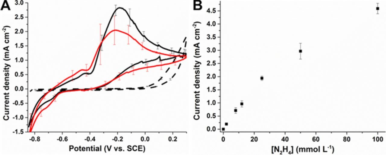
Figure 5. (A) Representative cyclic voltammograms for (dashed line) MWCNT-modified electrodes, (solid black line) 10% vPdNPs/vCNT PdNPs/MWCNT-modified electrodes and (red solid line) 12.5% vPdNPs/vCNT PdNPs/MWCNT-modified electrodes under deaerated solution in McIlvaine buffer (pH 7.0) in the presence of 8 mmol L−1 N2H4, at 10 mV s−1 during the first CV scan. (B) Calibration curve obtained at 10% vPdNPs/vCNT PdNPs/MWCNT-modified electrodes from cyclic voltammograms recorded at increasing concentrations of N2H4. Currents were taken at 0.1 V vs. SCE during the backward scan. Error bars represent one standard deviation from triplicate experiments.
BOx-based bioelectrode for O2 reduction
In order to develop the self-powered sensor, an enzymatic biocathode was employed as the cathode to pair with the optimized PdNPs/MWCNT-modified electrode as the anode. The standard biocathode used here for the enzymatic four-electron oxygen reduction reaction was described in our recent work.23 The biocathode exploits the use of negatively charged (5,5'-dithiobis(2-nitrobenzoic acid)) groups to provoke preferential orientation of the BOx enzyme toward the surface and thus facilitate efficient direct electron transfer for the oxygen reduction reaction. Figure 6 shows the CVs recorded at a GC-based BOx/(DTNB-Pyr)/MWCNT in quiescent solution and under oxygen purging. Firstly, for both oxygen conditions, the onset potential for the oxygen reduction reaction is Eonset = 0.52 ± 0.01 V. This is close to the redox potential of the laccase T1 copper center responsible for the intramolecular electron transfer to the T2/T3 site at which O2 is reduced to H2O. Comparison of the CVs recorded in quiescent solution and under oxygen purging reveal the drastic difference in catalytic current possible as a function of oxygen content. In buffer solution the dissolved oxygen is typically [O2] ≈ 0.2 mmol L−1 whereas under oxygen bubbling saturated oxygen levels of [O2]sat ≈ 1.2 mmol L−1 are possible. Under continuous oxygen saturation conditions, the maximum achievable current densities were 1.34 ± 0.15 mA cm−2 at 0.1 V, which compares to 0.06 ± 0.01 mA cm−2 at 0.1 V with only dissolved oxygen. After the addition of 8 mmol L−1 of hydrazine under oxygen saturation conditions with bubbling, a decrease of the observed resting potential from 0.52 V to 0.34 V was observed. Moreover, the voltammograms show that the O2 reduction onset potential was lowered to more negative potentials (Eonset = 0.35 ± 0.01 V) and with a noticeable decrease in cathodic current. This observation reveals that there is a competition between oxygen reduction from the BOx enzyme immobilized on the electrode surface and the electrooxidation of N2H4 in solution at the electrode surface (see Figure 5). Nevertheless, at high overpotential with Eapp = 0 V to 0.15 V, the maximum steady-state current densities obtained were identical to that recorded in the absence of hydrazine.
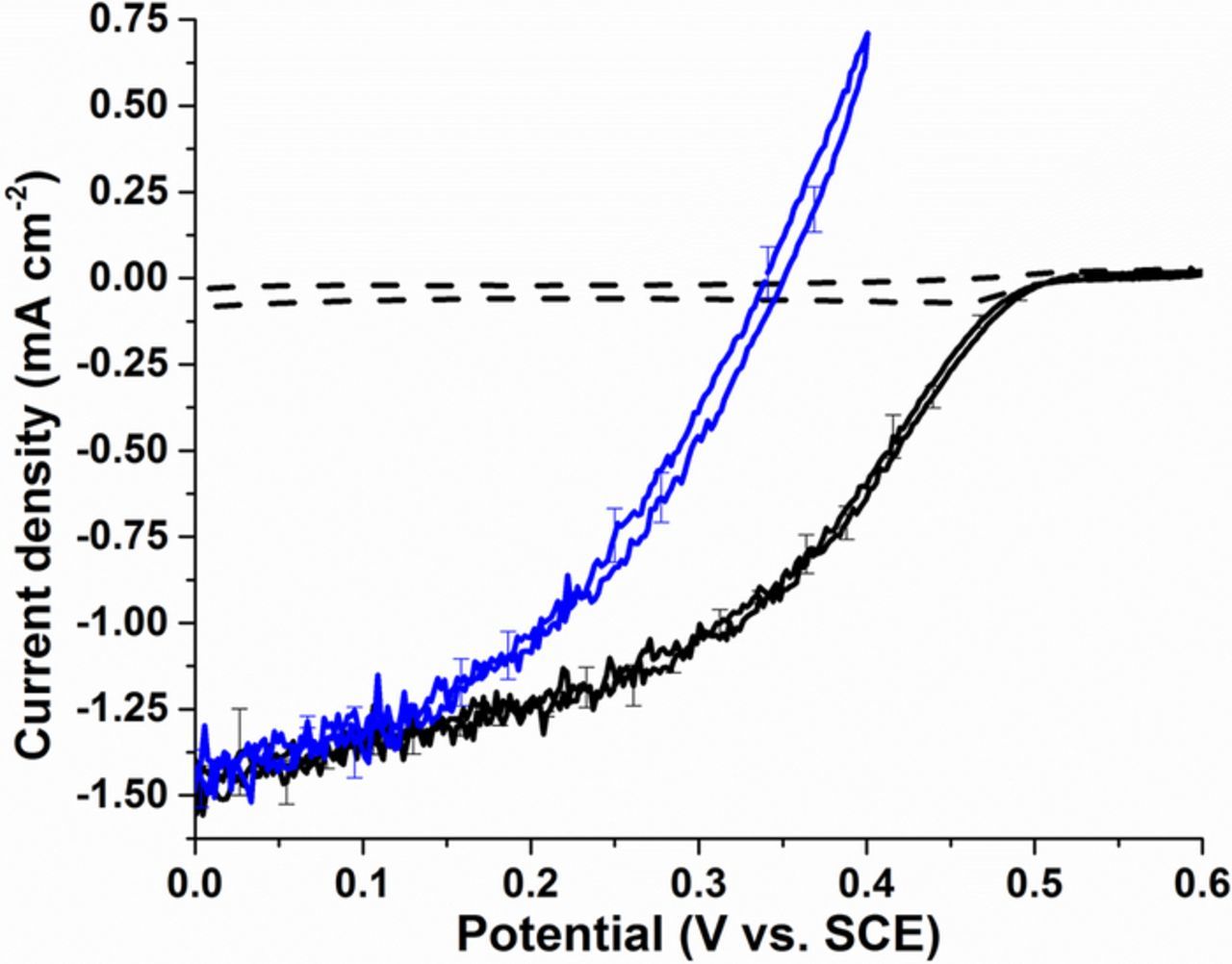
Figure 6. Representative cyclic voltammograms for BOx/(DTNB-Pyr)/MWCNT-modified electrodes under quiescent solution in the absence of N2H4 (dashed line) and under oxygen purging without (black solid line) or in the presence (blue solid line) of 8 mmol L−1 N2H4 solution in McIlvaine buffer (pH 7.0) at 10 mV s−1. Error bars represent one standard deviation from triplicate experiments.
Hydrazine self-powering sensor and remediation system
The complete hybrid N2H4 self-powered sensor was built by combining a PdNPs/MWCNT modified electrode as the anode and a BOx/(DTNB-Pyr)/MWCNT biocathode supported either on GC or GDL. In initial experiments, the GC-based biocathode was employed and oxygen was continuously purged to keep the oxygen solution concentration constant and to maximize power output (see cell configuration in Figure S1). The bioanode was prepared using the optimized anode prepared using the 10% vPdNPs/vCNT ratio which gave the highest catalytic activity for hydrazine oxidation. In the absence of hydrazine, the open circuit voltage (OCV) of the fuel cell / sensor was 147 ± 7 mV. Upon polarization of the electrodes between OCV and 0 V a maximum power density of Pmax = 0.2 μW cm−2 was obtained (Figure S2). Next, polarization curves were recorded for 10 different concentrations in the range of 0.2 to 15 mmol L−1 of hydrazine and the three parameters of OCV, Pmax and current density (Jmax) were monitored, and importantly, all three parameters increased with increasing hydrazine concentration. For hydrazine sensing, the maximum power density was measured from linear sweep voltammograms after each individual hydrazine injection into the solution, then a calibration curve was recorded presenting Pmax = f ([N2H4]) (Figure 7A). It can be clearly observed that the Pmax varies linearly with N2H4 concentration in the range of 0 to 4 mmol L−1 with a slope of 53.4 ± 3.4 mW L mmol−1 cm−2 (R2 = 0.994) before saturation is reached at a hydrazine concentration ≥ 6 mmol L−1 where Jmax = 937 ± 23 μA cm−2 and Pmax = 211 ± 30 μW cm−2, respectively. Finally, with the aim of alleviating the need for an oxygen source to operate the sensor device, for a more realistic sensor which could be applied at contaminated hydrazine sites, a second configuration of biocathode was employed. The biocathode was prepared as before but on a GDL substrate rather than GC (see cell in Figure S1) and in complete quiescent solution rather than under continuous oxygen bubbling. The advantage of the GDL is that oxygen can be brought to the cell system naturally via diffusion from the air giving increased currents compared to simple quiescent solution. Furthermore, the GDL electrodes further benefit from being lighter and more portable than typical GCE working electrodes. The device with the GDL-based cathode was operated and the data analyzed as described for the first self-powered sensor, and the results obtained were in agreement with those obtained previously (see Figure 7A). The only significant difference was regarding the limiting current obtained for this type of device which was slightly higher for the cell setup using the GDL-based biocathode. Additionally, the shapes of the power curves clearly indicate a diffusion limitation of the system at low concentration of N2H4 due to the absence of mechanic convection from the O2 purging. For GCE-based biocathodes this type of diffusion limitation was not observed due to very high rates of mass transport (see Figure S2).
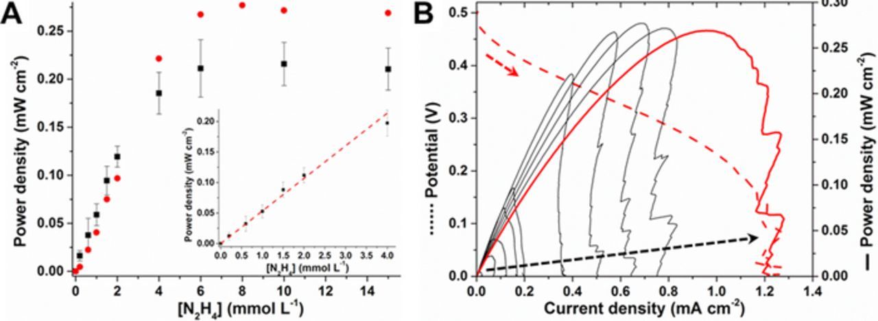
Figure 7. (A) (▪) Calibration curve for N2H4 sensing from 0 to 15 mmol L−1 obtained from maximum power density for each N2H4 concentration using the optimized anode and GC-based biocathode. (Inset: linear range for N2H4 quantification). ( ) Calibration curve for N2H4 sensing obtained with the GDL-based biocathode device. Error bars represent one standard deviation from triplicate experiments. (B) Representative power curves for the self-powered N2H4 sensor utilizing GDL-based biocathodes in quiescent solution in the presence of increasing concentration of N2H4 from 0.2 to 15 mmol L−1 as shown with the black dashed arrow. The curves were obtained from linear polarization curves recorded at 2 mV s−1 from OCV to 0 V as shown with the red dashed line.
Conclusions
A self-powered sensor has been developed which allows the electrochemical detection of hydrazine in solution without any additional external power supply and using a known environmental contaminant and natural oxygen as the fuels. Due to their remarkable catalytic properties, 22.5 nm diameter PdNPs immobilized onto a MWCNT matrix were used for the electrooxidation of the contaminant, hydrazine, in aqueous solution. This electrode was employed as an anode and combined with a BOx-based electrode as the cathode to form the self-powered sensor as a novel hybrid biofuel cell. This sensor exhibited a linear power response with increasing concentration in the range 0 to 4 mmol L−1 in continuously saturated O2 solution with a regular immersed biocathode with a glassy carbon support. To provide better insight into the practical use of the sensor as a future transportable sensing device, the biocathode was replaced with an air-breathing biocathode that alleviated the need of O2 supply from the system. The linear sensing range was equivalent to the one obtained using glassy carbon. In addition to providing the ability to detect hydrazine in solution, this hybrid self-powering device could be used "in the field" for the remediation of contaminated areas while generating green electrical current with the production of nitrogen gas and water as by-products. As a hybrid fuel cell, the open circuit voltage, maximum current density and the maximum power density were in the range of 0.5 V, 1.2 mA cm−2 and 0.25 mW cm−2, respectively, in quiescent solution. Ongoing research must be assessed to decrease the cross reaction of hydrazine oxidation with the biocatalytic reduction reaction at the cathode which reduces the open circuit voltage potential possible. Furthermore, a more efficient cell design for efficient gas removal from the oxidizing electrode is desired. Future work will address application of the sensor in contaminated waste waters.
Acknowledgments
The authors are grateful to CNPq and CAPES for financial support received under the COFECUB 2014 Program to complete this collaborative project. Additionally, this work was also supported by the Central Laboratory of Electron Microscopy (LCME) (TEM analysis) and the multiuser facility LDRX (XRD patterns) at UFSC. Further support was granted by the projects CAROUCELL (ANR-13-BIME-0003-02) and Labex ARCANE (ANR-11-LABX-0003-01). The authors would also like to thank the platforms "Surfaces Functionalization and Transduction" of the scientific structure "Nanobio" for providing facilities and "Microscopy" of the ICMG structure for SEM imaging.