Abstract
Electrochemical flow capacitors (EFCs) are a recently developed energy storage technology. One of the principal performance metrics of an EFC is the steady-state electrical current density that it can accept or deliver. Numerical models exist to predict this performance for specific cases, but here we present a study of how the current varies with respect to the applied cell voltage, flow rate, cell dimensions, and slurry properties using scaling laws. The scaling relationships are confirmed by numerical simulations and then subsequently by comparison to results from symmetric cell EFC experiments. This modeling approach permits the delimitation of three distinct operational regimes dependent on the values of two nondimensional combinations of the pertinent variables (specifically, a capacitive Graetz number and a conductivity ratio). Lastly, the models and nondimensional numbers are used to provide design guidance in terms of criteria for proper EFC operation.
Export citation and abstract BibTeX RIS

This is an open access article distributed under the terms of the Creative Commons Attribution 4.0 License (CC BY, http://creativecommons.org/licenses/by/4.0/), which permits unrestricted reuse of the work in any medium, provided the original work is properly cited.
The electrochemical flow capacitor is a new energy storage technology that has gained interest for grid-scale applications.1–4 EFCs store energy by charging the double layers that exist at the interfaces between the particles and an electrolyte solution in a flowable slurry electrode. The slurry particles with their charged surfaces are then subsequently transferred to external tanks for energy storage. The stored energy can be recovered by pumping these particles back through the cell during discharge. As is the case for flow batteries, external storage of the charged slurry allows for decoupling of power and energy capacity.
A schematic of a four-tank EFC is shown in Figure 1. This design consists of two half cells separated by a membrane. The membrane prevents electronic charge transfer between the negative and positive half-cells but permits the exchange of ions. During charging, slurry is pumped from tanks of uncharged particles through the cell in order to be charged; after passing through the cell this slurry is then stored in a separate set of tanks for charged particles.
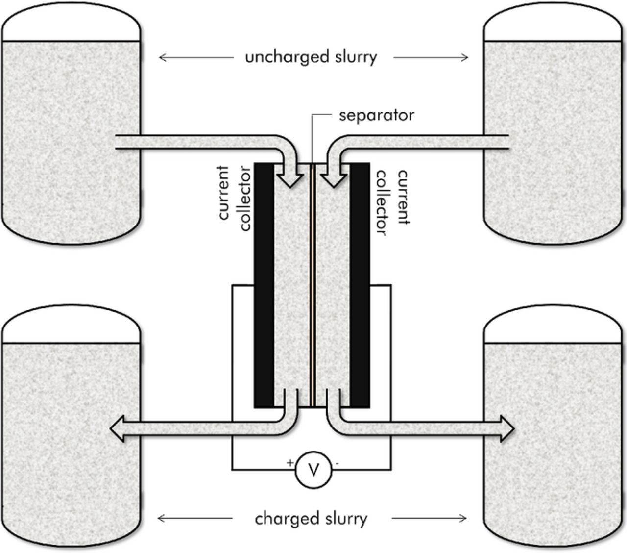
Figure 1. Schematic of a typical EFC during charging.
For this four-tank implementation, discharge then requires reversal of the pumps to redirect the charged particles back into the cell. This approach requires the double layer capacity of the entire slurry flow to be charged as fully as possible upon leaving the cell (i.e. the slurry needs to be fully utilized such that all of the available surfaces are charged to half of the voltage applied across the entire EFC cell). This four-tank approach allows immediate extraction of energy at the charging potential as all of the stored slurry at any point in time is fully charged. However, the necessity of fully charging the entire slurry stream can place severe restrictions on the maximum achievable current density. An alternative two-tank approach,5 foregoes the separate storage tanks for the charged and uncharged slurries and instead operates in a continuous mode. This approach is similar to the charging/discharging of conventional (non-flowing) capacitors. When operating in this mode larger currents are possible as it is no longer necessary to maintain full utilization of the slurry that passes through the cell. Immediate extraction of current at the full charging potential, however, is not possible as the stored slurry in the positive and negative tanks is not necessarily fully charged at any given time.
In both of these EFC implementations, the steady state current that results from a specific combination of flow rate, charging voltage, slurry properties, and cell dimensions is the performance metric of interest. In analogy to heat and mass transfer, this steady state current has been shown to be controlled by the formation of boundary layers of the overpotential as the slurry passes through the cell.6 In general, the potentiostatic charging of an EFC is therefore very similar to the Graetz problem7 from heat transfer. The Graetz problem involves the development of the thermal entrance region in a fully developed laminar flow upon encountering a heated section of wall along a channel. The boundary layers of overpotential that form in an EFC as the slurry passes the leading edge of the current collector held at constant applied potential are analogous to the boundary layers of temperature that form as the fluid passes the section of wall held at a constant temperature in the Graetz problem. As such, in order to understand the steady state current that an EFC can accept or deliver, scaling laws and nondimensionalization techniques similar to those from heat and mass transfer are therefore applied to EFC charging in this paper. The scaling relationships are first confirmed by numerical simulations and then subsequently compared to the results from single-tank symmetric cell EFC experiments.
Mathematical Model
The mathematical approach used to describe the capacitive charging of a flowable slurry electrode is identical to that developed by Hoyt, Wainright, and Savinell.6 The methodology is similar to the macroscopic approach used in earlier work by Newman for porous electrodes8,9 that was then subsequently applied to fluidized bed electrodes and slurry electrodes.10–12 Unlike the earlier approaches, though, advection of the overpotential/surface charge was included in the governing equations as described in reference 6 and repeated here.
The governing equations for the purely capacitive slurry are6
![Equation ([1a])](https://content.cld.iop.org/journals/1945-7111/162/6/A1102/revision1/jes_162_6_A1102eqn1.jpg)
![Equation ([1b])](https://content.cld.iop.org/journals/1945-7111/162/6/A1102/revision1/jes_162_6_A1102eqn2.jpg)
Here σ is an effective electronic conductivity of the slurry solid phase, Φ1 is the potential of the percolating electronic network, κ is an effective ionic conductivity of the solution, and Φ2 is the potential in the solution phase. The double layer capacitance is described by the quantities 'a' (which is the specific interfacial areal density — m2 of surface area per m3 of slurry-electrolyte volume) and 'C' (which is the capacitance per unit interfacial area). The combined quantity aC is the volumetric capacitance. It should be noted that the effective conductivities and capacitance values are not necessarily spatially uniform within an EFC.
Similar to what Johnson and Newman showed for porous electrodes,13 Equations 1a and 1b can be combined into an equation for the overpotential η = Φ1-Φ2
![Equation ([2])](https://content.cld.iop.org/journals/1945-7111/162/6/A1102/revision1/jes_162_6_A1102eqn3.jpg)
This single equation is not sufficient to fully describe the system (one of the initial equations must be retained in order to completely specify both Φ1 and Φ2), but this formulation is useful in that it indicates that the behavior of the overpotential is described by advection-diffusion analogous to heat or mass transfer. The presence of features such as boundary layers of overpotential thus arise. This equation can be simplified further still though the introduction of the electronic diffusivity from Johnson and Newman.13 The resulting equation is
![Equation ([3])](https://content.cld.iop.org/journals/1945-7111/162/6/A1102/revision1/jes_162_6_A1102eqn4.jpg)
where αe is the electronic diffusivity αe = κσ/aC(κ + σ) (with units m2/s). The equivalence of this equation to those in heat transfer naturally leads to analogous nondimensional parameters.
The work of Hoyt, Wainright, and Savinell6 introduced two of these parameters, the capacitive Péclet number and the capacitive Prandtl number. Each is shown below
![Equation ([4])](https://content.cld.iop.org/journals/1945-7111/162/6/A1102/revision1/jes_162_6_A1102eqn5.jpg)
![Equation ([5])](https://content.cld.iop.org/journals/1945-7111/162/6/A1102/revision1/jes_162_6_A1102eqn6.jpg)
For the capacitive Péclet number, U is the mean slurry velocity in the channel, and δ is the gap between the membrane and the current collector. This nondimensional number describes the rate of advection of the overpotential along the EFC channel compared to lateral diffusion across the channel. For the capacitive Prandtl number, ν is the kinematic viscosity of the slurry (i.e. its momentum diffusivity). This number describes the rate of growth of the overpotential boundary layers relative to the rate of growth of the hydraulic boundary layers. As the conductivities and specific capacitances are not necessarily spatially uniform, characteristic values of the slurry properties (such as the static values, or the average flowing values) must be used in these definitions depending on the context.
In our earlier work,6 the capacitive Prandtl number of a typical candidate EFC slurry was shown to generally be a very large number; this suggests that the overpotential boundary layers grow much more slowly than the hydraulic boundary layers with respect to distance along the electrode. The challenges of achieving satisfactory current densities in an EFC is therefore similar to the challenges encountered in heat transfer into high Prandtl number fluids – possible remedies of which include designs that break up the overpotential boundary layers or induce turbulence.
In this work additional nondimensional parameters describing the mathematical equations are introduced and the dependence of the device performance on these parameters is explored. Furthermore, scaling relationships in terms of these parameters are created and compared to numerical solutions.
Numerical Implementation
The numerical approach taken is identical to that in the earlier work of Hoyt, Wainright, and Savinell.6 A three-dimensional solver for the coupled set of equations 1a and 1b along with the associated Navier-Stokes equations for fluid flow was created using the OpenFOAM open source, finite volume CFD framework.14
The EFC was modeled as shown in Figure 2. For the sake of simplicity, the EFC geometry considered is that of a two-dimensional channel (although the solver is fully capable of more complex three-dimensional geometries). Due to symmetry, only the positive half-cell of the EFC is modeled. The applied potential across the half-cell ΔV0 (i.e. one-half the total voltage applied across the entire cell) is considered to be constant along the length of the electrode. As in the earlier work by the authors,6 the resistance from the separator was ignored as was any cell assembly or slurry-to-electrode contact resistance. Gradients in electrolyte concentration are also assumed to be negligible. The slurry is modeled as a laminar, Newtonian fluid, resulting in fully developed parabolic velocity profiles at the electrode due to the inclusion of sufficiently long entrance regions. This is only an approximation as the rheological properties of a real slurry are non-Newtonian in character and may possess slip at the wall;15,16 the development of the boundary layers of overpotential is similar with the Newtonian assumption though, so it is adopted out of simplicity. To ease comparison of the numerical results to the scaling relationships that are to be developed, aC and σ in the numerical approach are considered to have constant, uniform values regardless of the flow rate. This is an approximation as the electronic conductivity can be a function of shear rate.17 The assumption of a constant aC is also called into question for certain slurries (e.g. activated carbons) at low residence times where the ions may not have sufficient time to fully diffuse into micropores of the slurry particles.
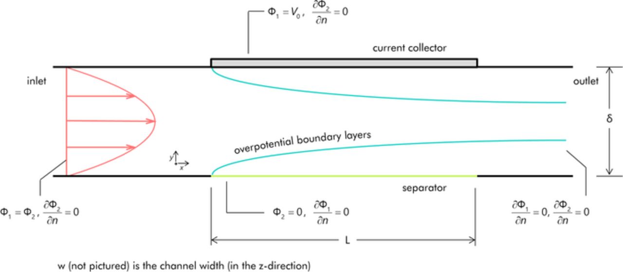
Figure 2. Setup for the two-dimensional model of the EFC positive half-cell. Boundary conditions are as indicated. Figure is not to scale. The fully developed velocity profile is as shown (a uniform velocity profile is used as the boundary condition at the inlet). Boundary layers of overpotential are created at both the membrane and current collector due to advection-diffusion of surface charge.
The performance metric of interest is the steady state current that the EFC can achieve; this value is found in the numerical simulations by performing an unsteady calculation over a sufficient time period to allow the initial transients to die away.
Experimental
Experiments have also been run for comparison to the models that have been developed. Unlike the aforementioned four-tank and two-tank EFC approaches, these experiments were performed using only a single tank. This approach is analogous to the symmetric cell experiments of flow batteries;18,19 instead of storing the positively and negatively charged slurries for subsequent discharge, the outflows from both half cells are simply remixed to a uniform uncharged state in the single reservoir. Doing so allows for consistent uncharged conditions at the inlets of the EFC half-cells.
Two completely separate experimental cases, Case 1 and Case 2, were performed. Each case used a different EFC cell and slurry composition. Parameters for the individual cases are shown in Table I below. Each EFC consisted of a rectangular channel with the geometric dimensions specified in the table (length L, width w, and channel gap thickness δ). Nafion 117 (DuPont, Wilmington, DE) was used as the separator.
Table I. Experimentally measured values describing the two separate EFC symmetric cell cases (Case 1 and Case 2).
| Case 1 | Case 2 | |
|---|---|---|
| σstatic (mS/cm) | 19.8 | 6.3 |
| aC (F/ml) | 2.39 | 15.7 |
| ΔV0 (V) | 0.05 | 0.5 |
| L (mm) | 51.0 | 20.0 |
| w (mm) | 6.0 | 6.0 |
| δ (mm) | 1.0 | 0.57 |
| AR1 | 51 | 35.1 |
| αe,static (m2/s) | 1.49×10⁻⁷ | 7.31×10⁻⁹ |
The Case 1 slurry consisted of 10 wt% Nano27 (Asbury Carbons, Asbury, NJ) carbon nano-platelets in 1 M H2SO4. The Case 2 slurry consisted of 6.5 wt% Nano27 carbon nano-platelets and 7.9 wt% YP-50 activated carbon (Kuraray Chemical Company, Osaka, Japan) in 1 M H2SO4. Nano27 has a BET surface area of 225–275 m2/g, and YP-50 has a BET surface area of 1500–1800 m2/g. Electrical impedance spectroscopy (EIS) under stationary conditions was used to determine their respective electronic conductivities. In a membrane-less cell, the low-frequency resistance of the impedance along with the cell's length-over-area factor were used to specify the static electronic conductivity value.17 The specific capacitance of the slurry was determined through potentiostatic charging of the slurry volume within the EFC cell; the total surface charge transferred to the particles was found by integrating the current until it decayed to zero. The resulting equation for aC appears as follows:
![Equation ([6])](https://content.cld.iop.org/journals/1945-7111/162/6/A1102/revision1/jes_162_6_A1102eqn7.jpg)
The experimental procedure to determine the performance of the EFCs consisted of potentiostatic charging of the flowing slurry across a range of flow rates. Flow was provided by a Masterflex L/S peristaltic pump (Cole-Parmer, Vernon Hills, IL). The initial transients in the current response were allowed to die away until the steady-state current could be determined.
Scaling Analysis of the Mathematical Model
Full numerical solution of the dimensional governing equations can be employed to determine the steady-state current that is achieved. Changes in flow rates, slurry characteristics, cell geometry, the voltage applied across the cell, and the charged state of the incoming slurry can all be explored through individual numerical trials. The use of nondimensionalization is advantageous in that it can lessen the number of numerical simulations to be performed by reducing the parameter space into fewer independent terms. Furthermore, scaling relationships based off of the nondimensional parameters can also be created to permit simple estimates of the expected current and to provide design guidance.
Nondimensional current scales
The principal quantity that is desired to be predicted by modeling is the steady-state current, I, that can be achieved by a particular EFC for a given cell voltage, flow rate, etc. Three different scales (i.e. characteristic current values associated with EFC performance) exist to nondimensionalize this current; depending on the context, one particular scale may be more useful than the others.
The analogous appearance of Equation 3 to advection-diffusion heat transfer leads to the first such scale, Idiff (i.e. the diffusion-controlled current). Analogously to the conduction heat transfer rate into a channel driven by a temperature difference, Idiff is a current that is driven by the total potential difference across the half-cell (ΔV0) divided by the diffusion-controlled resistance, Rdiff.
![Equation ([7])](https://content.cld.iop.org/journals/1945-7111/162/6/A1102/revision1/jes_162_6_A1102eqn8.jpg)
Here ηi is the uniform overpotential at the inlet; it is included in order to take into account the attenuation to the achievable current that results from partially charged particles being reintroduced into the cell when a two tank approach is used. Rdiff is equal to a length-over-area ratio multiplied by a resistivity value. Equation 2 shows the appropriate resistivity to be equal to the quantity (1/σ + 1/κ). Rdiff is hence,
![Equation ([8])](https://content.cld.iop.org/journals/1945-7111/162/6/A1102/revision1/jes_162_6_A1102eqn9.jpg)
Idiff is a measure of the current that results from the applied cell voltage as mediated through restrictions imposed by growth of the overpotential boundary layers. For a velocity profile that is fully developed by the time the flow reaches the leading edge of the electrode/membrane, dimensional analysis of the governing equations requires the quantity I/Idiff to be a function of at most three nondimensional variables: the capacitive Péclet number (Pec = Uδ/αe), the aspect ratio of the cell (AR = L/δ), and a ratio of the ionic and electronic conductivities (γ). The ratio of the conductivities could take various forms; κ/σ is the most obvious one. However, a more advantageous way to express this ratio is as γ = (κ + σ)(1/σ + 1/κ) – the reason for the selection of this particular expression will be discussed shortly. In general,
![Equation ([9])](https://content.cld.iop.org/journals/1945-7111/162/6/A1102/revision1/jes_162_6_A1102eqn10.jpg)
In analogy to the Graetz problem in heat transfer though,7 scaling in the longitudinal direction allows for Pec and AR to be combined into a single composite parameter, the capacitive Graetz number
![Equation ([10])](https://content.cld.iop.org/journals/1945-7111/162/6/A1102/revision1/jes_162_6_A1102eqn11.jpg)
Gzc is a newly defined nondimensional number similar to the Graetz number in heat transfer. The capacitive Graetz number characterizes the growth of the laminar overpotential boundary layers within the channel. Small capacitive Graetz numbers imply that the overpotential boundary layers will extend across the entire channel gap upon reaching the end of the current collector (hence fully utilizing the slurry). I/Idiff is therefore only a function of two independent nondimensional parameters. The functional relationship appears as follows:
![Equation ([11])](https://content.cld.iop.org/journals/1945-7111/162/6/A1102/revision1/jes_162_6_A1102eqn12.jpg)
The second current scale arises when considering the maximum charge that can be accepted by the double layers of the slurry particles as they flow through the cell. At the fully utilized limit (where the double layers at the exit of the cell are equal to the half-cell voltage), this current takes the form
![Equation ([12])](https://content.cld.iop.org/journals/1945-7111/162/6/A1102/revision1/jes_162_6_A1102eqn13.jpg)
Here  is the total volumetric flow rate of the slurry. A similar term has been called a "hydraulic current".4 After rearrangement, this capacitive current scale can be related to the diffusional current scale by the following relationship:
![Equation ([13])](https://content.cld.iop.org/journals/1945-7111/162/6/A1102/revision1/jes_162_6_A1102eqn14.jpg)
The capacitive current scale Icap is particularly useful when considering EFCs operating in a fully-utilized, single-pass mode (as depicted in Figure 1). An EFC operating as such must maintain a sufficiently high I/Icap ratio (as near to one as possible) in order to perform as intended, and must therefore be operated at a small capacitive Graetz number.
Idiff and Icap both have direct analogies in heat transfer and arise from consideration of overpotential advection-diffusion behavior. The third current scale, Iohmic, however, does not have a direct analogue. Unlike in heat transfer where increasing flow rates inexorably lead to higher heat transfer rates, Iohmic is an upper limit of the achievable current that is imposed by IR-losses alone (regardless of increases in flow). This limit comes into play at high capacitive Graetz numbers where the overpotential boundary layers become very thin and the utilization of the slurry is low. Under these circumstances, the parallel ionic and electronically conductive paths are both fully accessible and are not impeded by the presence of overpotential boundary layers. Similarly to Idiff, this current can be expressed as a total potential difference across the cell divided by a resistance:
![Equation ([14])](https://content.cld.iop.org/journals/1945-7111/162/6/A1102/revision1/jes_162_6_A1102eqn15.jpg)
The resistance in the Ohmically-controlled limit, however, takes the form
![Equation ([15])](https://content.cld.iop.org/journals/1945-7111/162/6/A1102/revision1/jes_162_6_A1102eqn16.jpg)
This form is equivalent to the high-frequency limit of electrochemical impedance spectroscopy (Rhf).20 Iohmic can be expressed in terms of Idiff as
![Equation ([16])](https://content.cld.iop.org/journals/1945-7111/162/6/A1102/revision1/jes_162_6_A1102eqn17.jpg)
The simplicity of this expression is the reason for selecting the specific form of the conductivity ratio γ that was adopted earlier. γ has a minimum value of 4 when κ/σ = 1, which shows that the Ohmic current scale is always larger than the diffusional scale. One additional advantage of this definition of the conductivity ratio is that γ is unchanged if the numerical values of the ionic and electronic conductivities are swapped. Swapping the respective conductivities changes whether the boundary layer principally grows outward from the current collector or from the membrane,6 but has no effect on the total current that is achieved; thus, having identical γ values for these two respective scenarios eliminates the need to run simulations for cases where, for example, σ > κ (as an equivalent case with κ > σ can be found).
It should be noted that if, in analogy to the convective heat transfer coefficient, an overall "capacitive current transfer coefficient"  based on the inlet value of (ΔV0-ηi) were introduced such that:
![Equation ([17])](https://content.cld.iop.org/journals/1945-7111/162/6/A1102/revision1/jes_162_6_A1102eqn18.jpg)
(where As is the geometric surface area of the current collector) then the quantity I/Idiff can be seen to be equivalent to a capacitive Nusselt number,  , defined as
![Equation ([18])](https://content.cld.iop.org/journals/1945-7111/162/6/A1102/revision1/jes_162_6_A1102eqn19.jpg)
Equation 17 is thus an analogous form of Newton's law of cooling as applied to capacitive slurry electrodes. A similar development based off of the log-mean difference between the inlet and outlet values of ΔV0-ηm (where ηm is the bulk value of the overpotential) is also possible.
Approximate solutions and operational regimes
Through the use of this scaling approach, an approximate solution for the variation of the steady-state current, I, with respect to changes in flow rate, cell geometry, and slurry properties can be found. This approximate solution is based off of the combination of individual solutions for three distinct operational regimes of an EFC.
The first regime is that of the fully-utilized slurry where the overpotential distribution across the entire channel at the exit of the cell is nearly equal to the voltage applied across the half-cell. As mentioned, this occurs at low capacitive Graetz numbers where the overpotential boundary layers from the current collector and membrane have sufficient space to grow and join together. In this regime, asymptotically 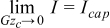 . The nondimensional currents can thus be expressed in the following forms, where the subscript '1' indicates that this relationship is for the first regime (i.e. the fully utilized regime)
![Equation ([19])](https://content.cld.iop.org/journals/1945-7111/162/6/A1102/revision1/jes_162_6_A1102eqn20.jpg)
![Equation ([20])](https://content.cld.iop.org/journals/1945-7111/162/6/A1102/revision1/jes_162_6_A1102eqn21.jpg)
The second regime is for moderate Graetz numbers where the overpotential boundary layers are able to freely grow but do not have sufficient time/space within the cell in order to extend across the entire channel gap. Due to the direct analogy to heat transfer implied by Equation 3, the scaling relationship governing the total EFC current is identical to the scaling relationship controlling the heat transfer rate in the Graetz problem.7 The scaling of the Lévêque solution to the Graetz problem21 therefore applies at sufficiently large Gzc. In general though, the boundary conditions on the overpotential differ from those of the canonical Graetz problem (i.e. Dirichlet or Neumann specifications) as the boundary conditions for the EFC model are specified in terms of Φ1 and Φ2, and not in terms of η directly. However, when IR losses become negligible (i.e. I/Iohmic is less than roughly 0.1), the sum of the overpotentials at the current collector and membrane nearly equals ΔV0 (i.e. a uniform value). Under these circumstances then, the EFC model acts identically to the standard uniform-temperature Graetz problem in a channel. As I/Idiff is directly analogous to the average Nusselt number from heat transfer, the standard Lévêque result for  for thermally developing flow in a channel can be used,22 resulting in the expression
![Equation ([21])](https://content.cld.iop.org/journals/1945-7111/162/6/A1102/revision1/jes_162_6_A1102eqn22.jpg)
Here c0 is equal to (3/2)2/3/Γ(4/3) = 1.467. Extensions to this Lévêque result are possible (i.e. the inclusion of higher-order terms of Gzc),23 but this has not been pursued. This specific value of c0 is valid for the fully-developed parabolic velocity profile of the Newtonian fluid; an alternative rheological model (such as the Ostwald–de Waele relationship) can be expected to alter the value of c0 somewhat (as has been shown for heat transfer24), but an examination of this effect has been left to a future paper.
Through their definitions, I/Icap and I/Iohm can be similarly expressed in this regime as
![Equation ([22])](https://content.cld.iop.org/journals/1945-7111/162/6/A1102/revision1/jes_162_6_A1102eqn23.jpg)
![Equation ([23])](https://content.cld.iop.org/journals/1945-7111/162/6/A1102/revision1/jes_162_6_A1102eqn24.jpg)
The third and final regime is the Ohmically limited regime. In this regime IR-losses dominate and, as discussed, the current becomes invariant of flow. Asymptotically, 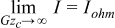 . Therefore
![Equation ([24])](https://content.cld.iop.org/journals/1945-7111/162/6/A1102/revision1/jes_162_6_A1102eqn25.jpg)
![Equation ([25])](https://content.cld.iop.org/journals/1945-7111/162/6/A1102/revision1/jes_162_6_A1102eqn26.jpg)
Each of these regimes therefore possesses a unique limitation that controls the magnitude of the current. For the fully utilized regime (regime 1), it is the inability to charge the slurry beyond the applied potential. At intermediate values of Gzc (in regime 2), it is the rate of development of the overpotential boundary layers. At high Gzc (in regime 3 — the Ohmically limited regime) it is the prevailing magnitude of the IR-losses. The three separate solutions for these respective operational regimes can be combined into a single composite curve to predict the steady-state current if it is assumed that smallest of these three unique limitations is the sole controlling factor. Hence, the quantity I/Idiff (as a function of the capacitive Graetz number and γ) can be expressed as by an approximate scaling solution as
![Equation ([26])](https://content.cld.iop.org/journals/1945-7111/162/6/A1102/revision1/jes_162_6_A1102eqn27.jpg)
where, again, the numerals 1, 2, and 3 refer to the expressions for the fully utilized, diffusivity limited, and Ohmically limited regimes respectively. Similar constructions can be performed for I/Iohmic and I/Icap. A qualitative plot of I/Idiff (equivalently, γ(I/Iohmic)) resulting from this assumption is shown in Figure 3. Plotted versus log scales, the results for each regime are represented as a line.
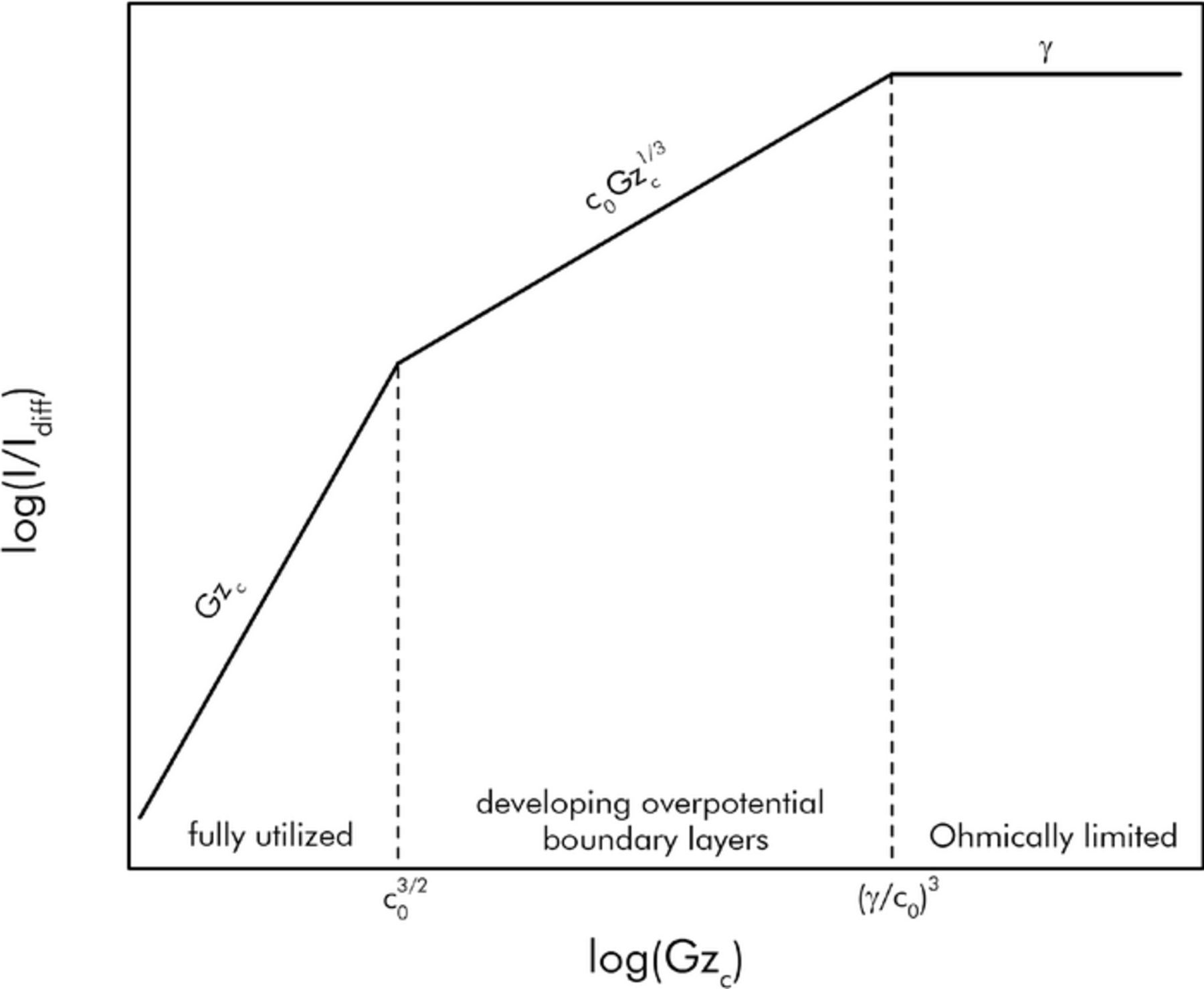
Figure 3. Prediction of the steady state EFC current I/Idiff using the composite construction of scaling results from the three operational regimes.
The plot of I/Icap is shown in Figure 4. This plot is useful for consideration of single-pass EFCs where the slurry is desired to be as fully utilized as possible.
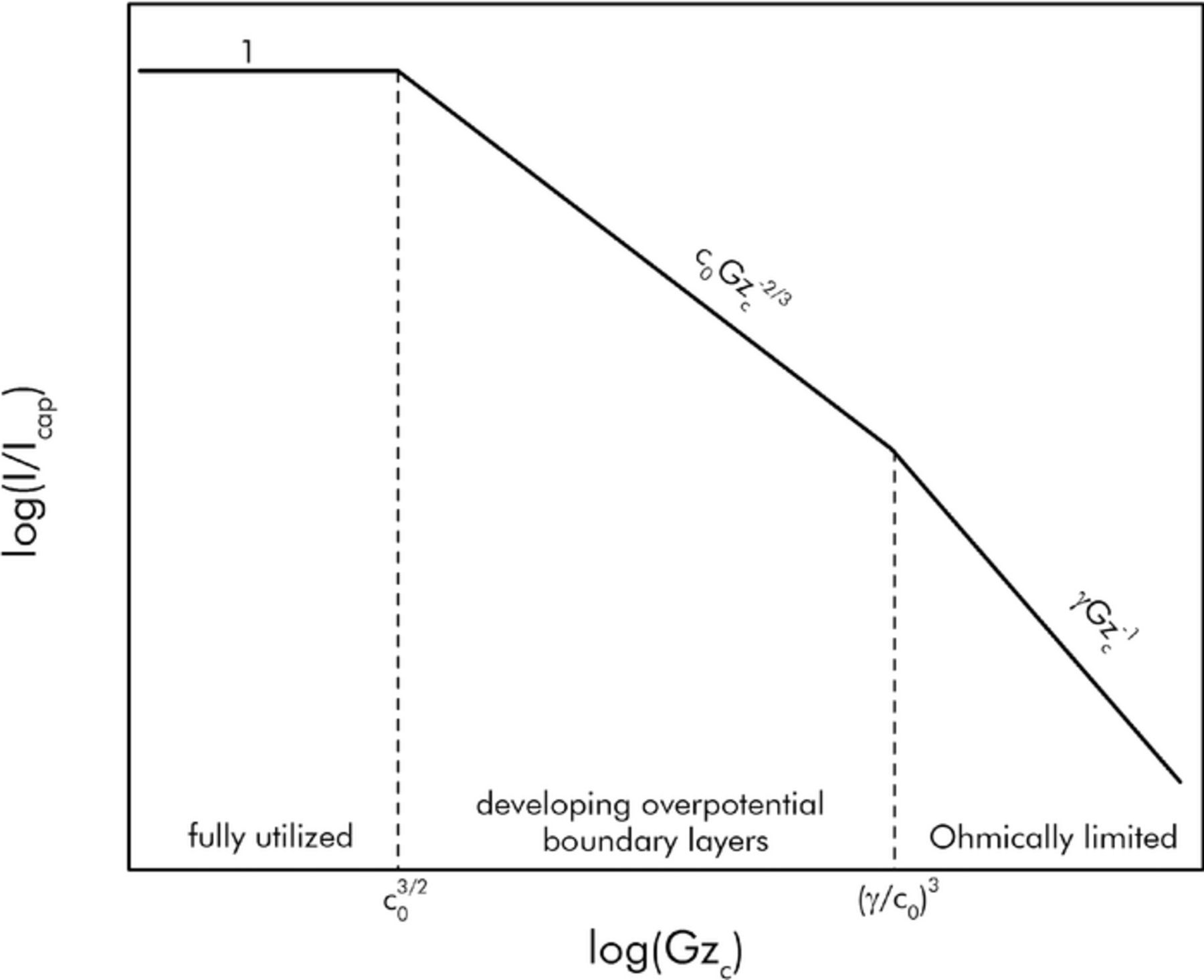
Figure 4. Prediction of the steady state EFC current I/Icap using the composite construction of scaling results from the three operational regimes.
In both of these plots, the transition from the fully utilized regime to the diffusivity limited regime can be calculated to occur at Gzc = c03/2. The transition from the diffusivity limited regime to the Ohmically limited regime can be calculated to occur at (γ/c0).3 In reality the transition between regimes does not occur abruptly at distinct capacitive Graetz numbers, but is spread across intermediate transitional zones. Comparison with numerical results from computational fluids dynamics simulations will be presented in a subsequent section to delimit this more fully. In general, the family of curves that result from this composite construction can serve as good upper estimates of the expected performance from a given EFC.
Results
Scaling and numerical modeling
In order to determine the validity of the above scaling relationships, computational simulations of the governing equations were run for a large number of combinations of flow rate, ionic conductivity, electronic conductivity, and specific capacitance of the slurry. The simulations were done in terms of dimensional quantities, and the results were subsequently nondimensionalized. As mentioned, in order to simplify the numerical/scaling comparison, in this section the slurry properties are considered to be uniform constants.
A plot of the numerically determined curves for I/Idiff versus the capacitive Graetz number for various values of γ are shown in Figure 5. As suggested by the scaling approach, the results were found to be dependent only on the capacitive Graetz number and the conductivity ratio γ. The composite scaling solution for each curve is also shown in the figure. The agreement between the scaling and numerical results is very good.
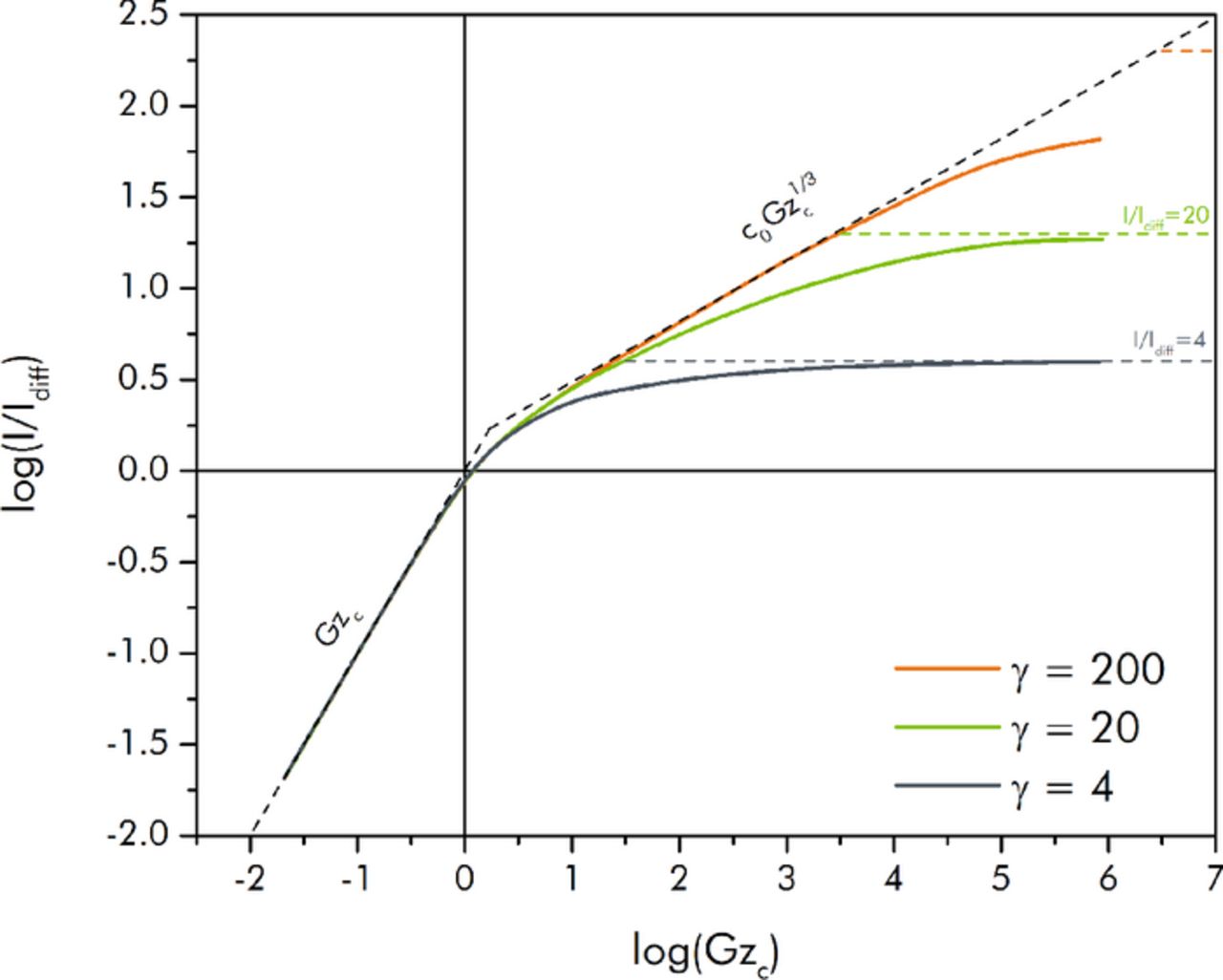
Figure 5. Nondimensional steady-state current I/Idiff (equivalently, γ I/Iohmic) versus capacitive Graetz number (Gzc) for various values of γ. Solid curves represent computational results, while the dashed segments represent the composite scaling solution.
In the fully utilized regime (away from the transitional zone), all of the numerically predicted curves match the scaling result in Equation 19 extremely well. For the diffusivity limited regime, the γ = 200 curve follows the scaling results of Equation 21 for a considerable range of Gzc, while the γ = 20 briefly does so. The γ = 4 case (where κ/σ = 1), however, does not. The reason this occurs is because the low Ohmic limit (relative to Idiff) in this case never allows the overpotential boundary layers to grow freely; thus, the two intermediate transitional zones that exist between the three respective regimes overlap, and the boundary layer growth behavior and scaling is never able to be expressed. As γ is increased (i.e. as the ratio of the Ohmic to the diffusional current scale is made larger) to values beyond those shown in the figure, the numerical solutions follow the c0Gzc1/3 scaling result for greater and greater extents of Gzc. Once Gzc is further increased all of the curves do begin to asymptotically approach the Ohmic limit from Equation 24 (although the γ = 200 case must be pushed to larger Gzc than those that were simulated in order to more fully achieve its limiting value).
A plot of the numerically determined curves for I/Icap versus the Graetz number for various values of γ are shown in Figure 6. This is the same data as in Figure 5 except related through Equation 13. The composite scaling solutions for each curve are again also shown in the figure. Not surprisingly, the agreement between the scaling and numerical results is again quite good. As mentioned, plotting the steady-state current scaled to Icap is useful when seeking to determine performance in the context of the four tank, single-pass EFC approach. For example, from these plots it can be ascertained that in order to utilize the slurry to a sufficient degree, the capacitive Graetz number must be maintained to be sufficiently low. For a desired 95% utilization requirement (i.e. if it is wished that the bulk overpotential of the fluid leaving the cell is at least 95% of the total half-cell potential; equivalently, I/Icap = 0.95), the numerical plots show that Gzc must be less than roughly 0.8 regardless of the conductivity ratio. For given slurry characteristics and a specified cell aspect ratio the only way to achieve a Graetz number this low is through the use of a low flow rate (which, in turn, could imply a very small steady state current). The scaling solution predicts a somewhat higher criterion for 95% utilization (Gzc = 1.91) because it does not account for the transitional zone between the two regimes that leads to earlier attenuation of the performance.
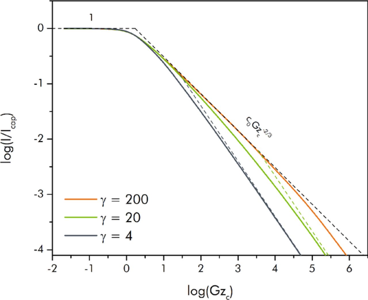
Figure 6. Nondimensional steady-state current I/Icap versus capacitive Graetz number (Gzc) for various values of γ. Solid curves represent computational results, while the dashed segments represent the composite scaling solution.
In general, the results in Figure 5 and 6 suggest that the scaling relationships can be used as reasonable upper estimates of the numerically predicted steady-state current from an EFC; a family of numerical curves for a variety of values of γ can be used when better predictions are required. In either case, for certain slurries possessing micropores the results must be applied cautiously when the residence time within the cell is small as sufficient time may not be available for ions to diffuse into the interior of the particles (thus making the assumption of a constant specific capacitance regardless of flow rate questionable).
Contour plots of the overpotential as calculated by the numerical model are shown in Figure 7 in order to demonstrate the characteristics of the three regimes qualitatively. For the fully utilized regime in Figure 7a, the overpotential of the slurry has uniformly reached the half-cell potential across the entirety of the channel as it proceeds downstream. At higher capacitive Graetz numbers, growth of the boundary layer of overpotential becomes far more visible, as in Figure 7b. As the Graetz number is made larger still, eventually the boundary layer becomes very thin as in Figure 7c, and the current becomes Ohmically controlled.
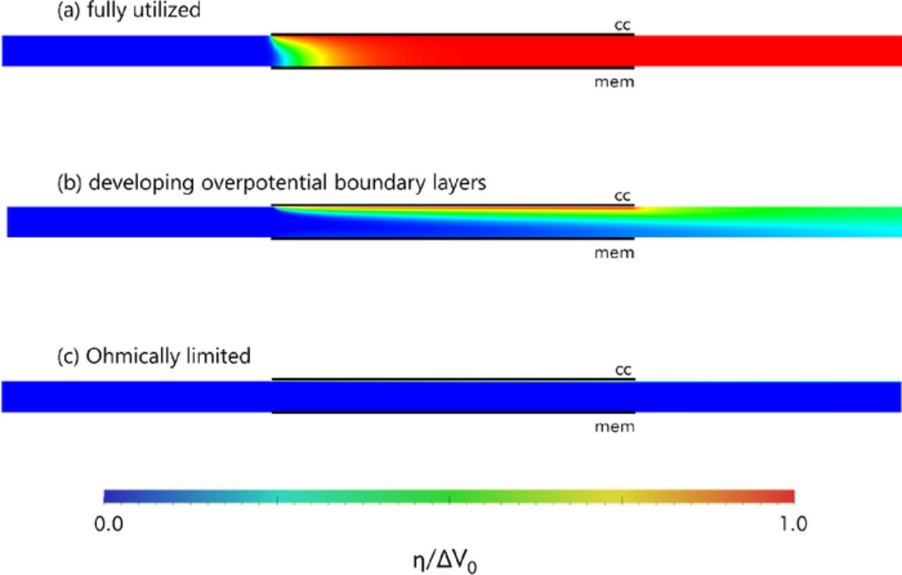
Figure 7. Contour plots of overpotential for the three operational regimes. Horizontal axis has been scaled by a factor of 1/3 for visual clarity. κ > σ for all cases. (a) Fully utilized regime (Gzc = 0.21, γ = 20) (b) Regime with developing overpotential boundary layers (Gzc = 8.7, γ = 20) (c) Ohmically controlled regime (Gzc = 87000, γ = 20).
Experimental results
As the scaling relationships have been shown to be consistent with the simplified numerical results (where the slurry properties were considered to be spatially uniform), experimental data has been taken in order to examine the applicability of these relationships to real-world EFCs. The experimental data consisted of the steady state currents that resulted from operation of the Case 1 and Case 2 single-tank EFCs at specified flow rates. Typical chronoamperometric data for Case 2 is shown in Figure 8 for a single flow rate (100 ml/min). As can be seen, an initial spike in the current upon the application of the cell voltage at t = 0 s quickly decays away until the current assumes a steady-state trend; the sinusoidal appearance of the data even during steady-state occurs due to the pulsatility of the flow as provided by the peristaltic pump.
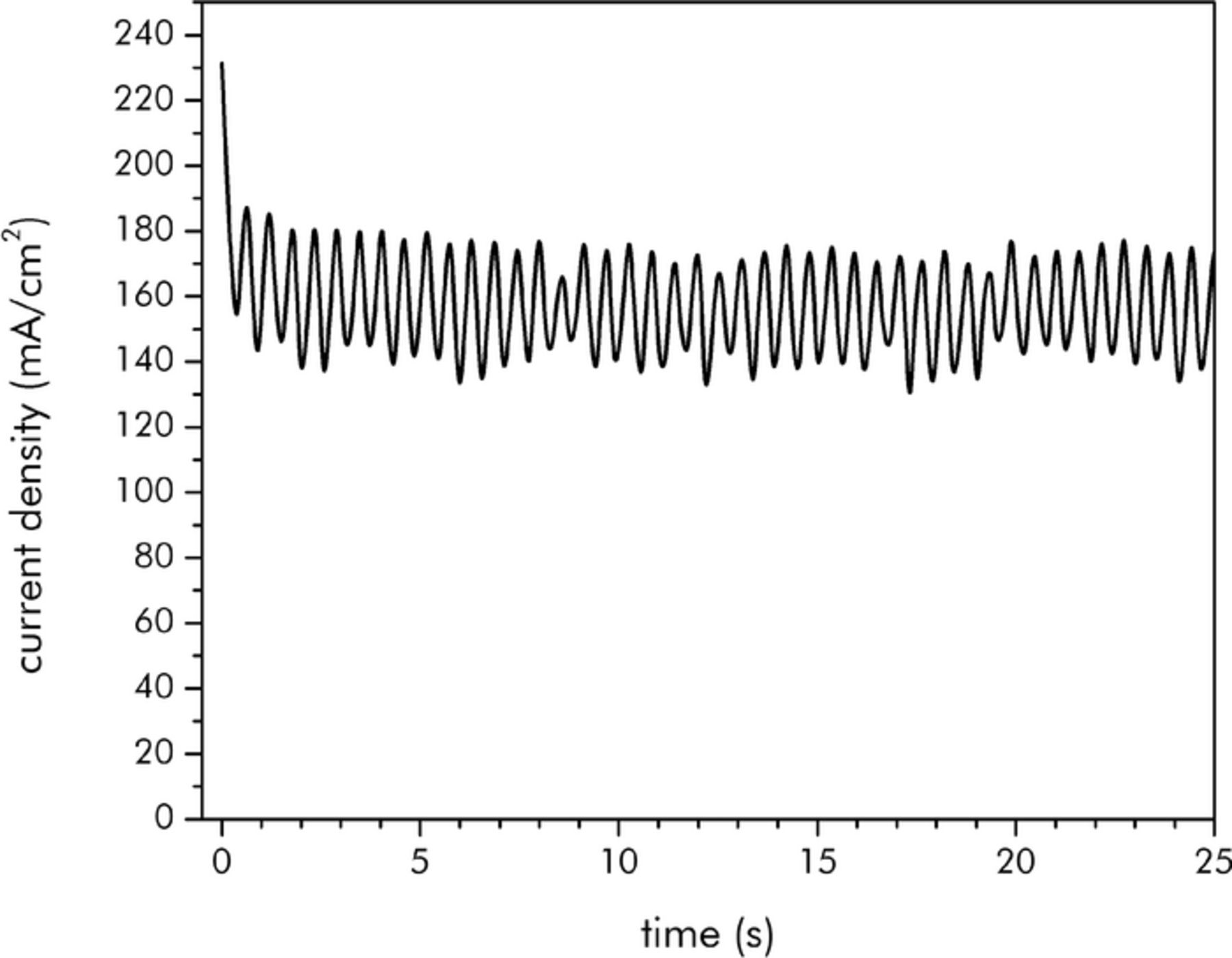
Figure 8. Chronoamperometry curve for Case 2 charging at 100 ml/min.
A plot of the steady-state current that resulted as such for Cases 1 and 2 across a range of flow rates is shown in Figure 9. This data is plotted in its raw, dimensional form. The somewhat limited range of flow rates selected (25 ml/min to 250 ml/min) are those that were permissible by the use of the peristaltic pump. It should be noted that Case 2 has current densities much higher than those reported in literature for EFCs (e.g. 100 times the 2 mA/cm2 at 13 ml/min reported in Porada, et al.5). This is because a far larger amount of conductive additive (in this case an additive possessing a high aspect ratio) was included, thereby ensuring a sufficiently large electronic conductivity, and, hence, a large electronic diffusivity. Admittedly, the specific capacitance of the Case 2 slurry is lower than that of the slurry used by Porada, et al., but as it is a flow capacitor with arbitrarily large tank size, using a slurry composition that favors high current densities in such a manner may be permissible.
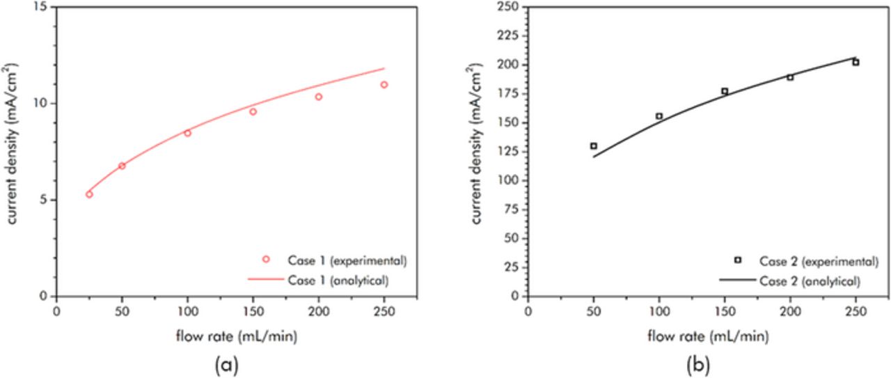
Figure 9. Steady-state current density (mA/cm2) for (a) Case 1 (Nano27 in 1 M H2SO4) and (b) Case 2 (YP-50 and Nano 27 in 1 M H2SO4) versus flow rate. Note: one reason for the large difference of the magnitude of the current densities between the two cases is that Case 1 was performed at a total cell potential of 0.1 V while Case 2 was performed at 1.0 V.
These results can be compared to the scaling predictions through use of nondimensionalization of the experimental data. This limited flow rate range from the peristaltic pump leads to an equally narrow range of the resulting Gzc for any particular case. As it was desired to show the experimental trend across as great a range of Gzc as possible, slurries of considerably different properties were selected for Cases 1 and 2. Case 1 is comprised entirely of the Nano27 high aspect-ratio conductive additive (and is hence, highly conductive but does not possess a large specific capacitance) while Case 2 is comprised of both Nano27 and the highly porous YP-50 activated carbon (and is hence modestly conductive with a far larger specific capacitance).
As is the case in the Graetz problem in heat transfer, specification of the appropriate fluid/slurry properties to be used in the nondimensionalization is challenging. In heat transfer, the fluid properties can change across the channel gap due to the dependence of viscosity, etc. on the local temperature. This variation leads to concepts such as that of the film temperature.7 For the nondimensionalization of the EFC results, similar complications arise.
The principal issue is that the applicable flowing conductivity value is difficult to specify. The ionic conductivity can be assumed to be the literature value of 1 M H2SO4 and can also assumed to be unattenuated by any Bruggeman-type effect as the volume fraction of particles in each case is less than 10%. The specific capacitance can also be treated straightforwardly assuming that flow rates are sufficiently low to prevent residence time effects from occurring — in those cases, the steady value of the specific capacitance can be used for each respective slurry.
The flowing electronic conductivity number though is more problematic. Generally the average flowing electronic conductivity value of a slurry as measured across the entire cell is a factor of two or so lower than its static value.25 However, this integrated average value is not necessarily suitable to describe the growth of the overpotential boundary layers as, for the flow rates used, the boundary layers are small and confined to a small region near the current collector. The growth is thus more accurately described by the local conductivity adjacent to the current collector. This near-wall region is where the largest shear rates are present, suggesting that the local value of the electronic conductivity would be lower there than the factor of two reduction alone. As uncertainty in the determination of the numerical value of this local conductivity exists, for the nondimensionalization it was assumed that the electronic conductivity for both experimental cases could be described by the static electronic conductivity value divided by an unknown factor (to be determined from a fit to the data). The single factor that was found to apply to both cases was 5.5.
Figure 9 includes the results from this scaling approach in dimensional form, while Figure 10 shows the experimental data that has been nondimensionalized accordingly along with the scaling solution. From Figure 10 it can be discerned that both of the sets of experimental results were in the range of Gzc such that the Lévêque scaling was applicable. As can be seen, the 1/3-power Gzc dependence was matched well by both sets of data. For Case 1, the exponent was determined from a least-squares fit to be 0.32 ± 0.01. For Case 2, the exponent was found to be 0.28±0.01. The slightly smaller exponent for Case 2 may be the result of residence time effects lowering the effective specific capacitance of the slurry at higher flow rates (as much of the surface area of the YP-50 slurry constituent comes from micropores).
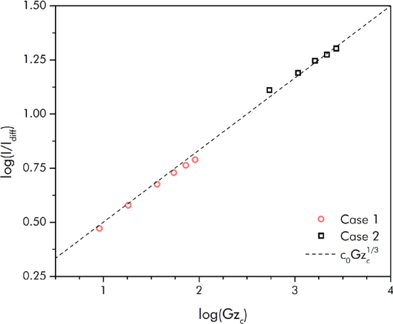
Figure 10. Scaling prediction and nondimensionalized experimental steady-state current versus capacitive Graetz number (plotted on log-scales in order to show the 1/3-power dependence); note: the nondimensionalization was based off a characteristic flowing electronic conductivity factor that resulted from a fit to the experimental data.
Alternative explanations also exist to account for the fact that the experimental current is much lower than predicted. For example, the presence of a contact resistance at the slurry/current-collector interface could also act to reduce the achievable current density. Earlier papers have noted that this contact resistance can be somewhat large; Dennison, et al. found it to be up to 40% of the high-frequency resistance of their EFC cell.3 Compared to the low-frequency resistance of the cell though (which is what is pertinent to actual EFC charge/discharge operations), the contact resistance they reported was negligible. Furthermore, reference 3 also reported that the contact resistance is significantly reduced with higher flow rates. As the flow rates used in the Case 1 and Case 2 experimental studies are much larger than those in reference 3, these combined facts suggest that the contact resistance would be negligible for our EFC system. Another resistance that could also act to reduce the charging current is that from the separator. Both the contact and membrane resistances, however, act in series with the effective resistance of the EFC that is predicted by the scaling approach. The exponent of the scaling solution for the experimental current with respect to capacitive Graetz number would thus be altered from the expected 1/3-power if either of these resistances were appreciable.
Thus, the close agreement of the scaling exponents from experiment and modeling (i.e. the fact that they are so close to 1/3) suggests that the EFC performance in our experiments is indeed governed primarily by overpotential boundary layer growth within a region near the wall where a linear velocity gradient prevails. It is unclear, however, why the electronic conductivity had to be reduced by a larger than expected factor from its static value in order to make the experimental results overlap with the scaling law result. More investigation must be performed in order to confirm that it is indeed localized attenuation of the electronic conductivity that is occurring due to the presence of the higher shear rates in the boundary layer region.
Discussion
Design guidance can arise from the mathematical relationships that have been developed. For example, the scaling results show that if operating in the Ohmically limited regime, raising the flow rates does not improve the total current that can be accepted or delivered by an EFC, but lengthening the electrode results in a linear increase in the total current (assuming the lengthening doesn't drop the EFC out of the Ohmically controlled region). If operating in the diffusivity controlled regime, the total current is proportional to L2/3, and U1/3 (again, assuming the alteration to Gzc doesn't push the EFC into another operational regime). In the fully utilized regime lengthening the electrode has no effect on the total current, but the current is linearly proportional to the flow rate. These relationships can dictate the cell geometrical dimensions and the slurry flow rates that should be chosen for an optimal EFC design, especially when compared to the changes to the pumping losses that would occur in concert. A full exploration of this optimization is not pursued here.
Additional design guidance can be offered specific to the fully utilized flow regime. If the electronic conductivity is much lower than the ionic conductivity (as is the case for most EFC slurries), then it can be shown that the maximum possible current density while still operating in this regime is
![Equation ([27])](https://content.cld.iop.org/journals/1945-7111/162/6/A1102/revision1/jes_162_6_A1102eqn28.jpg)
where icrit is the maximum possible current density for the fully-utilized regime and Gzc,crit is the critical capacitive Graetz number for 95% utilization (i.e. Gzc,crit = 0.8). This result is not a function of the specific capacitance of the slurry; for a given cell design, alterations to the value of aC can simply be countered by a commensurate alteration to the flow rate to achieve the same Gzc. This formula can be used to examine the practicability of grid-scale four-tank EFC systems as the current density that these systems can accept or deliver is generally one of the most important performance metrics. Capital cost models26,27 suggest that to reach target costs on the order of $200/kW, even if the costs of the electrolyte and slurry constituents are minor, any viable large-scale energy storage system needs to provide a current density of at least 100 mA/cm2. Assuming a channel gap of 1 mm and a total applied voltage of 1.0 V (potentials beyond which would require non-aqueous electrolytes), a flowing slurry electronic conductivity of 25 mS/cm would be required to achieve this minimum current density. This suggests a static conductivity value of at least 50 mS/cm or beyond is required for economic viability. Creating a slurry with an electronic conductivity this large while simultaneously maintaining a large specific capacitance (in order to minimize tank size and material costs) is a significant challenge, suggesting that the two-tank continuous flow option of Porada, et al.5 may be necessary. In the two tank case acceptably large current densities are possible as shown in Figure 9b, but these would necessarily be at an unacceptably low voltaic efficiency (the results in Figure 9b are, in fact, at a voltaic efficiency that is nearly zero). Furthermore, in this approach the power required to pump the slurry rises much faster with respect to flow rate than the 1/3-power at which the current density increases; inasmuch, any performance improvements from this option could be outweighed by pumping losses. Thus, it is clear that technical challenges remain for the EFC concept.
The modeling approach in this paper is applicable to systems beyond EFCs alone though. Flow batteries with flowable slurry electrodes present the same capacitive behavior as discussed for EFCs combined with simultaneous faradaic reactions. Inclusion of a faradaic transfer current to the model would permit simulation of these systems. The inclusion of mass transfer terms would furthermore allow the modeling approach to simulate capacitive deionization (FCDI) systems that utilize flowable slurry electrodes.28 Work toward this end is being pursued as future work.
Conclusions
In this paper, scaling relationships that allow for the prediction of the steady-state performance of EFCs were created. It was demonstrated that the performance of an EFC can be described in terms of two parameters, the capacitive Graetz number and the conductivity ratio γ. Depending on the particular values of these parameters, an EFC was shown to operate in one of three possible regimes: a fully utilized regime, a diffusivity limited regime, and an Ohmically limited regime. A composite scaling solution for the steady-state current that is achieved during charging at a given cell potential was discussed. These scaling results were compared to numerical solutions of the governing equations and good agreement was found. The scaling results were then compared to experimental EFC results in the diffusivity limited region of operation and the scaling exponents were found to match well. Guidance for future EFC designs was provided including discussions of a criterion delimiting the maximum permissible capacitive Graetz number for successful operation of a fully-utilized, single-pass EFC.
Acknowledgments
This work was performed under ARPA-E contract DE-AR0000352. Thanks to Nicholas Sinclair for construction of the EFC cell used in the Case 2 experimental study.