
Abstract
This work presents a platinum wire micro-reference electrode suitable for recording in-operando individual electrochemical impedance spectra of both the anode and the cathode in a proton exchange membrane water electrolyzer. The setup enables the protonic membrane potential to be accessed outside the active area. The reference electrode allows for the analysis of kinetic parameters for anode and cathode reactions separately. However, the exact location of the measured membrane potential is unknown due to a potentially asymmetric potential distribution, which makes the calculation of exact kinetic parameters non-trivial. Qualitative analyses of the potential distribution behavior over temperature, cell compression, and current density are shown.
Export citation and abstract BibTeX RIS

This is an open access article distributed under the terms of the Creative Commons Attribution 4.0 License (CC BY, http://creativecommons.org/licenses/by/4.0/), which permits unrestricted reuse of the work in any medium, provided the original work is properly cited.
The objective of this manuscript is to provide a comprehensive analysis of proton exchange membrane (PEM) electrolysis characterization via dynamic hydrogen reference electrodes (REs). This effort is part of the ongoing work to increase the efficiency and lower the capital costs of carbon-emission-free hydrogen production systems. Reference electrodes enable the study of the individual electrochemical performance of the half-cell reactions. Specifically, the cathodic hydrogen evolution reaction (HER), and anodic oxygen evolution reaction (OER) in the case of water electrolysis.1 Improved characterizations of the half-cell reactions and loss mechanisms in the cell lead to enhanced design of materials such as catalyst layers.2
It has been shown that a dynamic hydrogen electrode (DHE) can be used for in situ and electrode specific fuel cell (FC) potential measurement.3 A growing collection of work is now trying to apply these principles to PEM water electrolysis (WE) systems. Besides a DHE, other REs have been used in PEM systems such as salt bridges, pseudo-REs in between the membrane, or reversible electrodes by laser ablation. 4–6 These REs require adjustments to the materials, for example, an ionomer treatment of the porous transport layer (PTL) in case of the salt bridge or specific CCM preparation for the other two types.7 This work focuses on DHEs since they require minimal intervention in the cell material. Past approaches from FC research will be reviewed, followed by existing approaches for WE.
Much of the work on DHEs was pioneered for use in solid oxide electrochemical systems. Nagata et al. found that overpotentials could be measured between working and counter electrodes and a reference electrode. Edge-type REs, such as this, utilize the lines of constant potential that travel in-plane through the membrane and outside of the anode and the cathode active areas to record a potential. It was also noted then that the geometric placement of the electrodes within the cell affected the measurements. 8 Winkler et al. demonstrated this with simulations of different cell designs, showing the significant effect electrode misalignment can have—especially in the case of thin electrolytes.9 Adler et al. were then able to observe and quantify the distance requirement to avoid skewed measurement, for a reference electrode in a cell with perfectly aligned anode and cathode, to be three times the thickness of the membrane away from the active area. 10
With growing interest in PEM systems, this phenomenon was further modeled by Liu et al., under the assumption that half the membrane resistance could be attributed to both the working and the counter electrode in a PEMFC was found to rely on precise conditions, and that slight differences in electrode size and position could invalidate this assumption. 11 Experimentally, in the cases of PEMFCs, He and Nguyen found that the rate of electrode kinetics also affects a reference electrode's ability to measure at the mid-point of the membrane. 12 Li & Pickup implemented this concept with a DHE in a PEMFC and recorded single electrode results with minimal misalignment error. 13
With mounting evidence of this approach being successfully implemented in PEMFC applications, per above literature scan, interest in replicating it in electrolyzer systems has increased. A similar approach to the one used in the present study was carried out by Rakousky et al. in their respective PEMWE analyses. The authors used a direct current between two platinum wires placed in contact with the membrane on the cathode side of the cell. While no external hydrogen needs to be supplied, the exact hydrogen concentration at the RE is unknown. By doing this, they were able to collect half-cell potentials but could not distinguish any further electrode characteristics. 14
Thus far, previous approaches with DHE REs for voltage measurements have been reviewed. However, cell characterization usually includes methods beyond potential analyses. For comparison with the results of this paper, to conclude the review, we highlight work that has used various types of REs for advanced characterization methods.
Ideally, the implementation of reference electrodes into PEM systems allows not only for additional potential measurement locations, but also for characterization techniques such as Electron Impedance Spectroscopy (EIS) to be used for the collection of half-cell specific data. The benefits of using EIS in solid-state systems have been well-studied. 15 However, these results have primarily been collected in two electrode systems. Some ingenious solutions have previously combined reference electrodes and two electrode EIS to break down loss contributions. Since there have been successful examples in PEMFC applications,6,16–18 the proximate focus is on PEMWE. Kang et al. placed a pair of gold ribbons on the anode and cathode catalyst layers to measure anode, cathode, and catalyst coated membrane (CCM) resistances. 19 Nagasawa et al. used a liquid electrolyte compartment enable measurement outside the active area on each side of the CCM. Their work presents a dissection of full cell ohmic losses into separate contact resistances at the anode and the cathode and into membrane resistance as well. 20
If a third electrode can be placed between the anode and the cathode, the high-frequency resistance can be attributed between the two half-cells. To achieve this, Sorsa et al. and Hartig-Weiss et al. sandwiched a micro-platinum wire between two single-sided catalyst coated membranes to create a pseudo-reference electrode. 21,22 While Hartig-Weiss et al. chose a location in the active area for their sensing position, Sorsa et al. coated an electrode ring around a round-shaped catalyst layer to place upon their reference electrode. Thus, both works did not require perfect alignment. In the latter work, the observed EIS sees near-expected attributable splits in the high frequency resistance (HFR) region, with some artifacts believed to be associated with side reactions. In the work of Hartig-Weiss et al., EIS was only measured at open circuit voltage (OCV) conditions. The reason was that the RE potential was affected under operation. Xu et al. used a DHE to study anodic catalyst materials. Since the focus was primarily on the anode results, the EIS results were all to that effect. 23 All methods mentioned above successfully diagnose at least partial sources of efficiency loss in their respective cells. Some methods provided more insight than others, thereby demonstrating that despite difficulties associated with EIS combined with REs in PEM electrolysis, there is value in using the technique.
Based on the past and current research efforts, three next steps are identified and elaborated on in the present contribution. Going beyond half-cell potential analysis, the RE in the present work is used to specifically study the kinetics of the cell and the associated kinetic parameters. DHE REs have been used in the past but are rarely subjected to structural measurement uncertainty testing. This is to be accomplished in the present work. Moreover, the DHE setup is combined with EIS measurements, and the potential distribution is analyzed based on the EIS results for the first time.
This paper will address the three research aspects with a DHE made of a micro-platinum wire in contact with the membrane outside the active area in an isolated compartment of humidified hydrogen. The contact point is at least three times the membrane thickness away from the active area in order to access the uniform potential region. This setup is the enhanced WE version of the FC setup used by Herrera et al. 3,24 A total of 119 individual tests are carried out to assess the RE reproducibility. The results of the half-cell potential with HFR measurements, and kinetic analysis lead to a discussion on the prevalence of misalignment in solid state systems and the benefits of using EIS to diagnose it. Finally, the robustness and the limitations of the method are discussed through a set of variations of influencing parameters.
Reference Electrode: Materials and Methods/Experimental
Setup and working principle
The setup description starts with an outline of the standard test cell and the testing equipment. Thereafter, the working principle of the RE is described. On this basis, the corresponding modifications to the cell are explained and the materials employed for the RE are listed.
The research cell is designed for PEMWE and manufactured by Fraunhofer ISE. It has a 4 cm2 active area, gold-plated titanium current collectors, and end plates with flow fields built in. Details can be found in Ref. 25. Surrounding the raised flow fields are polyether ether ketone (PEEK) gasket seats. The cell is equipped with porous transport layers (PTLs). The PTLs are located in contact with the flow fields. In between the PTLs, a CCM is positioned. Details on the PTLs and CCMs are given in the following subsection with each measurement protocol. Once assembled, the cell is mounted in an electrolysis test station (Greenlight Innovation E20) for experiments. The test station provides anodic and cathodic water recirculation loops with temperature control. The cell is connected to a potentiostat (SP-150 with VMP3B-5 from BioLogic) for electrical measurements.
Next, the working principle of the RE is explained. The DHE is based on the concept of the hydrogen's standard electrode potential. Therefore, a platinum surface in contact with an electrolyte and hydrogen is required. On the platinum surface, the hydrogen equilibrium reaction takes place. The electrode thus has a stable and known potential. Accordingly, the main requirements for the DHE are as follows. The platinum wire needs to be flushed with hydrogen. Furthermore, it needs to be electronically and ionically contacted. Finally, the wire needs to touch the membrane and the membrane needs to have moisture. Since the aim is to measure the membrane's protonic potential, the touchpoint must be located outside the active area.
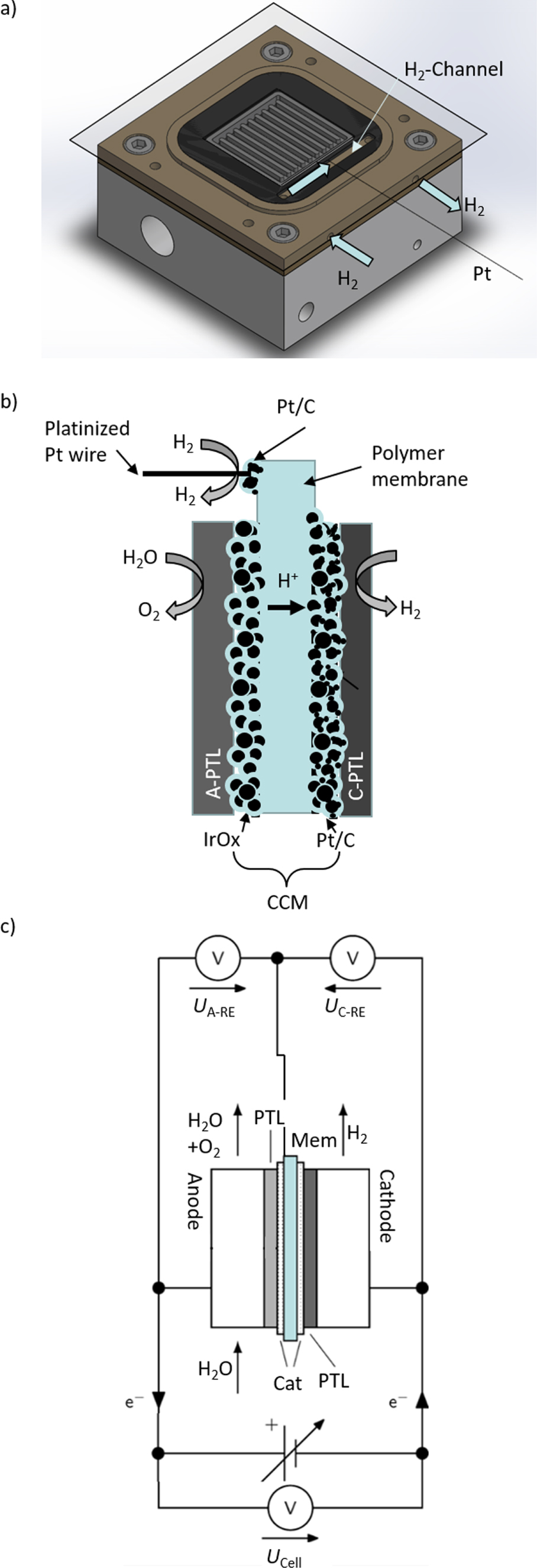
In order to fulfill the main requirements, the research cell is equipped with an additional compartment in the PEEK frame. The compartment allows humidified hydrogen to be circulated and is located outside the active area of the membrane. Figure 1a shows a technical drawing of a modified cell. The PEEK frame on the anode side is machined to provide the inlet and outlet for the humidified hydrogen gas compartment (highlighted). A gas loop is created from outside the cell into the middle of the gaskets. More precisely, this is made possible by removing a portion of the gasket above the holes bored out of the frame so that the gas flows over the membrane. This region is outside the active area but inside the compressed zone of the cell.
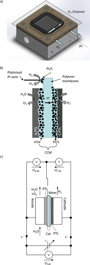
Figure 1. Setup of the platinum wire reference electrode, (a) technical drawing of the modified electrolysis cell electrode block with platinum wire, (b) sketch of the experimental setup, (c) measurement specifications in RE-setup.
Download figure:
Standard image High-resolution imageLastly, the materials for the RE are outlined. The DHE consists of a 59 μm thick polytetrafluoroethylene (PTFE)-insulated platinum wire. Only at the two ends of the wire is approximately 5 mm of the insulation removed, one end for contact with the measurement device, and the other has been additionally platinized to increase the contact area towards the reference electrode. The method of Ives & Janz is used for platinization. 26 Scanning electron microscopy (SEM) images of the platinized platinum wire can be found in Fig. S1 in the SI. This end of the wire is then placed on a section of the membrane with an additional platinum spray patch added. The recipe for the platinum patch and a picture of the prepared CCM can be found in the SI (Fig. S2). Figure 1b shows a typical 5-layer PEM cell with the platinum patch on the membrane and the location of the DHE. As mentioned above, this membrane location is positioned over the cut-out gasket and the PEEK frame's hydrogen inlet/outlet ports. It is crucial to ensure this measurement point is always far enough away from the active area to have the best chance to measure the potential in the uniform potential area. Figure 1c shows the measurement device connections.
Measurement protocol
The measurement protocol for testing is described as follows. First, the general preparation procedure is outlined. Second, the specific RE-related tasks are described. Lastly, the individual protocols for the three research questions are presented.
For each test, the cell flow fields are rinsed with DI water for cleaning and dried with compressed air. PTLs are cleaned in an ultrasonic bath for 15 min. The CCMs are placed directly into the cell in a dry state. Once the components are in place, the cell is compressed to approximately 1 kN to ensure no internal movement. The cell is then connected to the test station. Anode and cathode water recirculation at 60 °C with a flow rate of 0.5 l min−1 is used. Thermal conditioning is carried out by running the water recirculation for 30 min with an unpolarized cell. This period also allows for the membrane to expand as it becomes saturated. Once complete, the cell is compressed to 2.5 kN, and a timer is set for 5 min to allow the system to settle (normally leading to small relaxation of the compression). Then, the cell compression is raised back up to 2.5 kN.
The RE-related tasks encompass the hydrogen flow provided by an FC test station (Greenlight Innovation G20) close to the WE test station. Specifically, the hydrogen flows at a gas temperature of 35 °C with a relative humidity of approximately 75%. Initially, the temperature was set to 60 °C, which is the cell temperature. However, cooling down of the tubing due to atmospheric contact lead to water condensation within the tubes. A stable RE potential without water condensation could only be achieved with 35 °C hydrogen feed. The flow rate is set to 0.01 LPM.
In the following, materials and electrochemical test protocols are presented. Results are divided into cell characterization, RE reproducibility assessment, and HFR measurements. The HFR measurements include a subsection on temperature and compression variation effects.
Cell characterization
First, polarization measurements at ambient pressure conditions are recorded. Polarization behavior is assessed by a galvanostatic step profile with current density steps between 0.005 and 1 A cm−2 with impedance measurements at every current density step for determining high-frequency resistance RHF. A frequency range of 100 kHz to 0.1 kHz with 11 points per decade is used. The amplitude for EIS is set to 5 mV. The polarization measurements are carried out thrice. Throughout the manuscript, the following materials will be referred to as standard materials. The standard PTL materials are titanium fiber PTL with a thickness of 0.2 mm for the anode side and carbon paper for the cathodic PTL (Freudenberg, E20H). The standard CCM is a 127 μm thick Nafion™ membrane with catalyst loadings of 2 mgIr cm−2 and 1 mgPt cm−2 (Hiat). The exemplary cell characterization in the results section is shown for a low loading CCM (0.5 mgIr/cm2 and 0.5 mgPt/cm2 (Hiat)) and an iridium-coated PTL. Material indications can also be seen in Table S1 in the SI. The characterization is carried out at a water and cell temperature of 80 °C.
RE steadiness
As the next step, 119 experiments are carried out to analyze the functionality of the reference electrode. The stability tests consist of a constant current hold at 100 mA cm−2 for 5 min. The majority of the experiments are carried out with materials as those described in the cell characterization procedure. In addition, the following materials are used to investigate the influence of different materials on the results. Tests 14–24 are carried out with a two-layered PTL on the anode side. During tests 43–50, lower catalyst loadings (0.5 mgIr cm−2 and 0.5 mgPt cm−2, HIAT) and iridium-coated PTLs are used. Materials specifications can also be found in Table S1 in the SI.
Potential distribution analysis based on EIS
In the framework of the HFR measurements and potential distribution analyses, water recirculation temperature and cell compression are changed. The temperature variation is performed with cathode PTL and CCM, as described in the cell characterization section. However, the anode PTLs are two-layered titanium fiber material (Numbers 14–16 in Table S1 in the SI). A run-in at 60 °C, with the cell being compressed to 2.5 kN, is carried out as a first step. Therefore, the cell characterization protocol presented above is used. In the second step, water is cooled to 40 °C, the third is heated to 60 °C, and the fourth to 80 °C. Each time, the cell characterization measurement protocol from above is carried out.
Last, the cell compression is varied. The cell is run in at 60 °C and compressed to 2.5 kN. Then the compression in the system is reduced to 1.25 kN, then stepped up to 3.25 kN in 1 kN steps. The measurement protocol from the cell characterization procedure presented above is carried out at each step. Material is outlined in the temperature variation and corresponds to 17–19 in Table S1 in the SI.
Potential distributions with RE
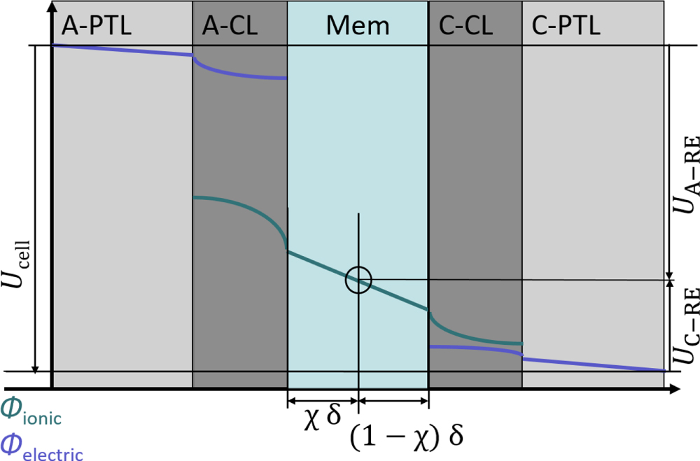
So far, it is outlined that the RE senses the protonic potential of the membrane. However, the potential in the membrane depends on the position, e.g., inside/outside/at the edge of the active area. This subchapter explains the potential distribution within the cell and gives theoretical background. Figure 2 displays the protonic and electronic potential distribution for a typical PEMWE cell. It should be emphasized here that the figure and subsequent explanations are given under the assumption that the measured ionic potential lies within the limits of the membrane potential. The work of He et al. shows that in extreme cases a potential can be measured which exceeds this range. 12
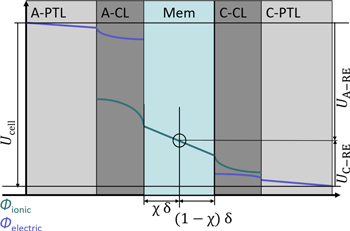
Figure 2. Electric and protonic potential distribution in a typical 5-layer PEM water electrolysis cell, RE outside the active area, indication of potential measurements.
Download figure:
Standard image High-resolution imageA general equation for the cell potential can be found in Ref. 7. The cell voltage can be further decomposed into the anode and cathode contributions (Eq. 1).

Equation 1 shows that the main factors in cell potential gains (kinetic losses, mass transport losses, and ohmic losses Rel, RH+, Rmem) occur on both the anode and cathode. The overpotentials related to reaction kinetics are denoted with ηact and those related to mass transport with ηmt. The contributing effect of the ohmic resistance is broken down between the protonic resistance in the CLs, which RH+ cl represents, and the electronic resistance within the bipolar plate (BPP), PTLs and the CLs written as Rel bbp, Rel ptl, and Rel cl, respectively. The electrode on which these factors occur are denoted with a superscript "A" for the anodic contributions and a superscript "C" for the cathodic contributions. Further electrode-specific resistances can occur at the interfacial points within the cell, specifically between the PTL and the CL of each electrode, Rptl|cl,A and Rptl|cl,C. Furthermore, the interface between the BPP and PTL can contribute to the total ohmic resistance, Rbbp|ptl,A and Rbbp|ptl,C. Subsequently, the contributions from the BPP will be neglected for simplification. However, a reference electrode is required to measure these effects—the working principle of which will be described subsequently.
With the RE, the two voltage measurements between the RE and the electric potential of the anode and cathode can now be provided in addition to the full cell voltage Ucell measurement. Figure 2 indicates the voltage measurement locations, and the corresponding definitions can be found in Eqs. 2 and 3.


Contributions in the measured voltages for RE to the anode can be found in Eq. 2. The share of Rmem H+ depends on the ionic potential distribution in the membrane, especially outside the active area. Here, the factor Χ is introduced to account for the location of the corresponding equal-potential line in the active area. Χ can be between 0 and 1. In the case of a symmetric potential distribution, it would result in Χ = 0.5. For RE to the cathode (Eq. 3), the remaining share of the ionic resistance in the membrane (1- Χ) Rmem H+ is included.
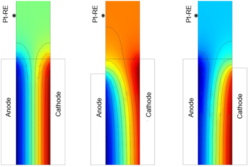
The effect of misalignment on the ionic potential at the RE location can be seen in Fig. 3. For ideal conditions (left, no misalignment of the CLs and similar kinetics for both electrodes), the RE senses the potential of the middle of the membrane. If the cathode CL is larger than the anode CL (middle), the ionic potential at the RE location is closer to the one at the cathode. In the opposite case (right), the RE senses closer to the anode. According to He and van Nguyen, symmetry is also disrupted by different kinetics at the anode and cathode. Specifically, a slight bending of the equal-potential line towards the faster electrode occurs. 12 For the present case, even with perfectly aligned electrodes, the RE location would be shifted towards the anode side to a small extent. Moreover, the importance of locating the reference electrode at a distance of three times the membrane thickness away from the edge, as stated earlier, becomes visible. The edge effect leads to a non-uniform potential when moving closer to the active area.

Figure 3. Effects on the potential profiles of the misalignment of the anode and cathode electrodes in a solid electrolyte, after Herrera et al. 27
Download figure:
Standard image High-resolution imageData evaluation: HFR and tafel analysis
Subsequently, the steps for the evaluation of measured data are explained. The steps include a correction of the measured potentials by the RE's potential, evaluating EIS measurements, and a common approach for kinetic analysis.
Potential of RE
Measured voltages are corrected by the potential of the Pt wire and thus presented against SHE potential. See Eq. 4 for the cathode measurement. The same procedure is valid for the anode.

The potential of the platinum wire, EDHE, depends on the surrounding humidified hydrogen flow and can be calculated via the Nernst equation, Eq. 5.

In Eq. 5, R is the gas constant, T is the local temperature (35 °C), F is Faraday's constant, cH+ Mem is the proton concentration in the membrane, and pH2 is the partial pressure of the hydrogen gas. Proton reference concentration equals 1 mol l−1. A proton concentration of 0.54 M for fully saturated Nafion™ was found in the literature. 28 This concentration corresponds to a pH value of 0.27. No information was found regarding the dependence of membrane proton concentration on the operating current. Therefore, the value is assumed to be constant in the course of this work. The partial pressure of hydrogen can be calculated via the measured pressure in the FC test station's inlet tube, the relative humidity (RH), and the partial pressure of water vapor. The latter can be calculated from Antoine's equation (Eq. 6). The constants were obtained from the National Institute of Standards and Technology based on Bridgman and Aldrich data. 29

The partial pressure of hydrogen is calculated according to Eq. 7. The pressure in the humidified hydrogen line precirc is set and controlled during the experiment.

Data evaluation for EIS measurement
The HFR is measured via EIS. It is assumed that the ohmic cell resistance equals the measured high-frequency impedance, where the imaginary part of the impedance equals zero. In this work, it is calculated by linear interpolation of data at the intercept with the x-axis (-Im = 0) in the Nyquist plot. This procedure is well known in full cell measurements. In this contribution, additional half-cell HFR values are measured. A typically obtained Nyquist plot is presented in Fig. 4a. Materials used for this example correspond to number 50 in Table S1 in the SI. In some cases, several intercepts with the zero-axis can be found. In these cases, the intercept at lower frequencies is used to calculate the HFR value (RHF). Figure 4b is a higher magnification of Fig. 4a focusing on the cathode-to-RE (C-RE) signal. At frequencies above 28 kHz, the Nyquist diagram displays artifacts in the form of large outliers. In the course of this work, the share of the respective half-cell HFR from the full cell HFR is shown. The value is calculated by dividing the half-cell HFR by the full cell HFR.
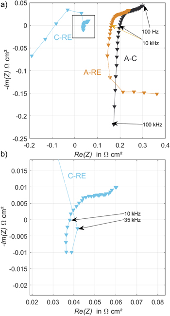
Figure 4. Nyquist plot of anode (A)-RE, cathode (C-RE), and total cell impedance (A)-(C) for tested at 0.25 A cm−2 with amplitude of 5 mV and frequency range from 100 kHz to 0.1 kHz. Used for determination of RHF. Figures (a) and (b) show different magnifications of the same data.
Download figure:
Standard image High-resolution imageData evaluation for kinetic analysis
Data from polarization and HFR measurements are used together to calculate the HFR corrected voltage. This is shown for the full cell measurements in Eq. 8 but also applies to half-cell measurements.

Calculating HFR corrected voltages ( ) is a necessary step to be able to complete the Tafel analysis. In this work, the Tafel analysis is carried out via linear interpolation in a logarithmic current density region, 0.01–0.1 A cm−2, of the HFR corrected voltage for the full cell. It is assumed, that all other losses are negligible at these low current densities. This is demonstrated in Eq. 9, where ηact, the kinetic overpotential, is the difference between
  and the reversible full cell voltage Urev, b is the Tafel slope, and i0 [A cm−2] is the apparent exchange current density. Again, equations are shown for the full cell but also apply to both half-cells.

For large overpotentials, the Tafel analysis is justified. For small kinetic overpotentials, it is common to simplify the Butler-Volmer equation with a linear approximation. The linearity between the kinetic overpotential and current density is shown in Eq. 10, where αf is the charge transfer coefficient for the forward reaction and αb for the backward reaction.

For comparison, the Tafel approximation is used first for all kinetic analyses. It should be noted that the HER is usually a fast reaction and crosses into the linear approximation range. Linear regression is carried out when the Tafel approximation results in low b and large i0 values. The sum of the charge transfer coefficients αf and αb can be assumed to equal one. 30
Tafel fitting for the half-cells is described in Eq. 9. The Nernst potential for each electrode can be calculated as follows in Eqs. 11 and 12, where cH+ CL is the proton concentration in the CL. The product gases are assumed to be fully humidified at the reaction site. Reference concentrations are equal to 1 mol l−1.


While the proton concentration in the membrane used in Eq. 5 is a literature value of 0.54 M, the value for the ionomer of the CL is unknown. Proton concentration in Nafion™ depends on the water content. 28 For PEMFC, the water content in the CL is lower compared to the membrane. 31 For PEMWE, no study was found regarding water contents in Nafion™ CLs. Moreover, the proton activity at the reaction site (catalyst particle) might be locally different from the bulk CL. The proton activity is uncertain, yet it plays a critical role in determining the reversible potential of the cathode and consequently impacts the kinetic analysis of the HER. Below, we will provide a brief analysis of the influence.
The sensitivity of EC,rev to ccl H+ is shown as follows for two cases. First, the potential is calculated with the membrane proton concentration of 0.54 M. Second, the Nafion™ volume fraction in the CL is assumed to be 25%. All other influences on the proton concentration discussed above are neglected. Thus, a proton concentration of 0.54/4 M is used. It should be noted that this is only valid on a macroscopic scale. At 60 °C and ambient gas pressure at the electrode (not to be confused with hydrogen pressure in the recirculation line for the DHE), EC,rev(0.54 M) is −15.1 mV while EC,rev(0.14 M) is −54.9 mV. This leads to a change in i0 in Eq. 9 in multiple orders of magnitude. In this work, the latter value is used for kinetic analysis. Moreover, it is not clear if the proton concentration changes with different operating currents. Future investigation via in operando pH measurements at the CL is required to validate the assumption of a fixed pH value.
Results and Discussion
First, the resulting voltage and impedance measurements are shown and used to enhance the loss breakdown. Second, the precision of the RE measurement will be discussed. Therefore, measured values of UC-RE are presented to discuss how stable they are throughout 119 measurements. Third, the effect of misalignment becomes the main focus. Statistics of the share of anode and cathode HFR throughout 49 measurements are presented. The effect of misalignment is artificially engraved to verify the assumptions from earlier works. Through a variation of temperature and theoretical models, ohmic resistance is split into temperature and non-temperature-dependent contributions. An additional study with compression force variation and its effect on the share of anodic and cathodic HFR contributions is presented.
Cell characterization
In the following, results from cell characterization measurements are presented. This subchapter offers a use case of the RE, which leads to an improved loss breakdown. The voltages of the full cell and half-cells as a function of current density for a low loaded CCM and iridium-coated PTL (SI, Table 1, Setup 50) are presented subsequently. Figure 5a shows the voltages. The cell voltage, in black, increases as expected over current density. The anode-to-RE voltage (A-RE, orange) is slightly lower and increases less over current density. The cathode-to-RE voltage (C-RE, blue) lies below zero and decreases over current density. The general trends follow the expectations. Figure 5b shows the corresponding HFR for full cell and half-cells over current density. The HFR is stable in a range of 200–220 mOhm cm2. The anode-to-RE HFR lies in a range of 160–190 mOhm cm2 and the cathode-to-RE in a range of 30–40 mOhm cm2. The anode and cathode HFR sum lies within 95% of the measured full cell HFR. As stated in Eqs. 2 and 3, the half-cell HFR values include different contributions, such as catalyst, interface, and PTL resistances. These differ for the two electrodes since different materials are used. Moreover, the HFR values include unequal shares of the membrane resistance due to the unknown misalignment factor. When interpreting the impedance spectra, it should be taken into account that the potential distribution within the membrane also depends on the current density. According to He and van Nguyen, the potential detected by the RE changes at different current densities due to the different kinetics at the anode and cathode. 12 For simplicity, it is assumed in the present work that the shift of the equivalent potential lines is minimal at the EIS amplitudes used here.
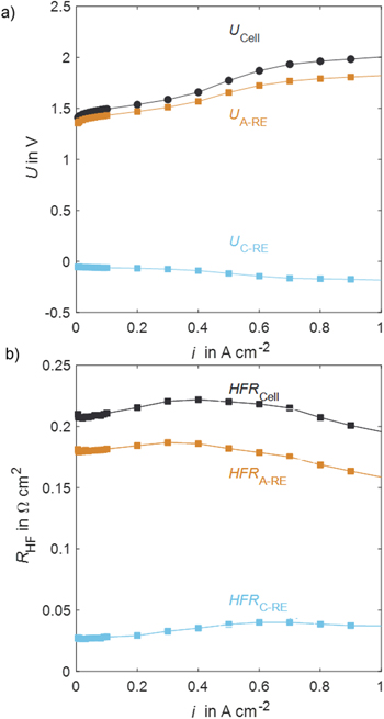
Figure 5. Cell voltage analysis of a PEM water electrolysis cell with a low loaded CCM and iridium-coated PTL material at 80 °C with RE: (a) Polarization curves, (b) HFR over current density.
Download figure:
Standard image High-resolution imageA kinetic fitting for the full cell and half-cells is carried out as a next step. Figure 6a shows the HFR corrected full cell voltage over current density. The Tafel slope is 48 mV dec1, with a 95% confidential interval (CI) of [47,50], and the exchange current density 6.2⋅10−8 A cm−2, 95% CI [4.4⋅10−8, 8.9⋅10−8]. Figure 6b shows the kinetic analysis for the OER. The Tafel slope is 42 mV dec1, 95% CI [41, 43], and the exchange current density 1.2⋅10−8 A cm−2, 95% CI [8.0⋅10−9, 1.8⋅10−8]. Figure 6c shows a linear fit for the HER to complete kinetic analysis. Previous Tafel fitting resulted in small Tafel slopes and large exchange current densities. Thus, a fast reaction is verified, and Eq. 10 applies. The resulting exchange current density from linear fitting is 269.4⋅10−3 A cm−2, 95% CI [235.2⋅10−3, 315.3⋅10−3].
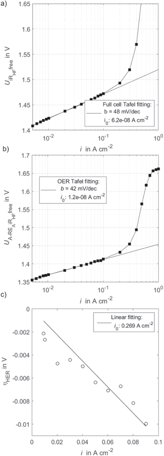
Figure 6. (a) Full cell Tafel analysis, (b) OER Tafel analysis with HFR corrected half-cell voltage, (c) HER linear approximation regression analysis with the HFR and Nernst potential corrected C-RE signal.
Download figure:
Standard image High-resolution imageAs mentioned, analysis is carried out with a proton concentration of 0.14 M. This value only considers an estimated volume fraction of Nafion™ in the CL and no other impact factors such as water content or local effects. The determined kinetic parameters are in good agreement with recently published values, where a different RE was used.7 There, the Tafel slopes for OER were measured between 49–51 mV dec−1. OER exchange current densities were measured between 7.03⋅10−8 to 1.0⋅10−7 A cm−2. HER exchange current density from linear fitting resulted in 186.9⋅10−3 A cm−2.7 Generally, the measured Tafel slope and exchange current density fall in the same range. The present work resulted in a slight shift towards lower b and larger i0 for the OER. In other words, the OER kinetics appeared to be faster in the present work. For HER, i0 resulted in slightly larger values. However, the applied materials were moderately different, e.g. catalyst loadings.
RE reproducibility
After demonstrating a use case for the RE, this subchapter thoroughly studies the reproducibility of the DHE RE. Figure 7a shows the measured voltage UC-RE vs SHE over the number of tests. Measurements with a different PTL type (SI, Table 1, Setup 14–24) and intentionally misaligned electrodes (SI, Table 1, Setup 4–7 and 25–33) are marked individually since these setups resulted in large outliers. The remaining 95 tests are labeled with average test. Tests with the same assembly typically have more similar values than newly assembled cells' measurements. The median value of the 95 tests is −34.6 mV. The standard deviation is 30.7 mV. Tests without Pt patches (number 75 and higher) result in larger deviations.
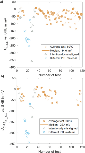
Figure 7. (a) Voltage UC-RE throughout testing at 100 mA cm−2, 5 min average, 60 °C–80 °C cell temperature, ambient pressure, (b) HFR corrected voltage only for tests with EIS measurement, test without EIS are left out.
Download figure:
Standard image High-resolution imageAs shown in Eqs. 3 and 4, the measured value includes EC,rev, ηC act, Rptl|cl,C el , Rptl,C el, Rcl,C el, Rcl,C H+, parts of Rmem, and ηC mt,. These contributions can differ within the tests. Out of these contributions, the ohmic resistances can be measured. For 62 tests (material used is indicated in Table S1 in the SI), EIS measurement is carried out, and the half-cell HFR can be assessed. Figure 7b shows the corresponding HFR corrected values for these tests. The median value is −22.4 mV. The standard deviation is 22.5 mV when discounting the outliers, as discussed above.
The remaining contributions after HFR correction (EC,rev, ηC act, ηC mt) can differ from setup to setup. As seen in Fig. 7, the different PTL material and the intentionally misaligned electrodes resulted in large deviations. This can be due to changes in mass transport or activation losses.
Another impacting factor is the proton concentration on EC,rev, as shown in Eq. 11. A change in pH from 0.27 (proton concentration equals 0.54 M) to 0.85 (proton concentration of 0.14 M) resulted in a voltage difference of approx. 40 mV. In addition, the potential of the RE varies due to local changes in temperature and relative humidity.
In conclusion, the RE itself includes an uncertainty that is more pronounced for different assemblies and smaller for different tests with identical setups. Especially for sensitive kinetic analysis such as exchange current densities, a possible RE potential inaccuracy should be considered. In spite of that, the RE is successfully utilized in a large number of experiments.
Potential distribution analysis through share of HFR
In the following, a focus on the HFR share between the anode and cathode is set. The subsequent part includes a statistic on how anode and cathode contribution to cell HFR is distributed. Moreover, the HFR share is influenced by misaligning the electrodes, varying the temperature, the cell compression, and the current density. Through these variations, the disadvantage of the unknown symmetry factor Χ should be overcome to enable even more advanced voltage loss breakdown. However, quantitative analysis is limited.
Investigation of HFR share
Misalignment of anodic and cathodic CL and different kinetics are known to influence the potential distribution outside the active area. While misalignments result in shifts in both directions depending on which electrode is shorter, kinetic effects cause shifts towards the electrode with faster reaction kinetics. In the context of PEMWE, this translates to a shift towards the cathode, thereby resulting in a greater HFR at the anode. Therefore, this work aims to analyze these effects, with an emphasis on misalignment, on the current measurements. Therefore, the share of anode vs cathode HFR is calculated for all tests with EIS measurement. The results can be seen in Fig. 8. Material coincides with the one in Fig. 7b and is indicated in Table 1, SI.
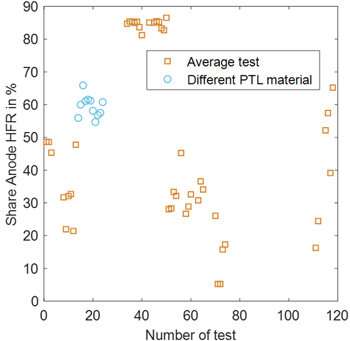
Figure 8. Share of HFR of RE towards Anode from full cell HFR at 100 mA cm−2 for data from reproducibility testing except for intentionally misaligned experiments.
Download figure:
Standard image High-resolution imageIn some cases, the HFR of anode-to-RE accounts for half of the ohmic resistance. In other cases, it lies above or below 50%. A certain variation of the anode-to-RE HFR is expected due to different contributions from, e.g., contact resistances between CL and PTL on the anode and cathode side. However, large variations between 6 and 85% are expected to be caused by asymmetrical potential distribution outside the active area of the membrane. In other words, the symmetry factor changes drastically throughout cell setups and even different tests with identical setups. It cannot be assumed that the symmetry factor is around 0.5. This inhibits any further improvement of the loss breakdown, e.g., dissection of the ohmic resistance into its contributions.
In addition, an SEM image of a CCM cross-section can be found in Fig. S3 in the SI. The image points towards a misalignment of the anode and cathode CLs.
Intentional misalignment
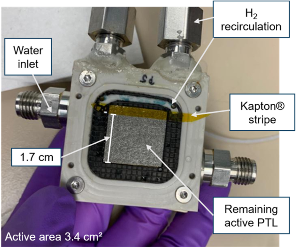
As discussed in the previous section, misalignment is a possible cause that limits further loss breakdown. Testing has shown that it appears to be present in the majority of the cases. As a first step to analyzing this limitation, an extreme case is designed. Namely, the active areas are intentionally misaligned by consecutively covering a part of the PTL on the anode and cathode sides. The setup for a covered anode can be seen in Fig. 9. The remaining active area was measured with a caliper to 3.4 ± 0.02 cm2. Materials used correspond to numbers 6–8 in Table S1 in the SI.
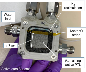
Figure 9. Picture of PEMWE anode block with specifications about the setup for intentional misalignment. Original active area (4 cm2) is reduced to 3.4 cm2.
Download figure:
Standard image High-resolution imageEven though the area underneath the PTL covered with Kapton® is isolated electrically, and from fluid transport, the CL in that region might still participate to a lower amount in the reaction due to in-plane electric and mass transport in the CL. Therefore, the exact active area is expected to be larger than the uncovered area. However, HFR values will be presented as area-specific values for the uncovered area.
For a covered anode PTL, the potential at the RE is expected to shift closer to the cathode side (compare Fig. 3, middle). Therefore, a smaller HFR from the RE towards the cathode is expected. For a covered cathode PTL, the HFRA-RE is expected to be lower. Measurements follow these expectations, as can be seen in Fig. 10. For non-covered PTLs, the HFRA-RE is smaller than the HFRC-RE. This can in parts be explained by faster cathode kinetics, as explained in the materials and methods section, and in parts points towards a larger anode. Values are measured at a current density of 1 A cm−2. The absolute values can be found in Table S2 in the SI. The sum of HFR towards the anode and cathode slightly deviates from the measured full cell HFR. Therefore, the percentages in Fig. 10 do not add up to 100% in all cases.
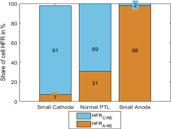
Figure 10. Share of anode-to-reference and cathode-to-reference HFR for different misalignments.
Download figure:
Standard image High-resolution imageIn previous works, intentional misalignment is used to isolate the CL, PTL, and contact resistances from the membrane resistance. 20 From the present measurements, the sum of CL, PTL, and contact resistances for the anode is expected to be smaller than 12.5 ± 0.07 mΩ cm2 and, on the cathode side, 3.5 ± 0.02 mΩ cm2. However, these values can still include a fraction of the membrane resistance. Moreover, the actual active area is unknown, increasing the uncertainty of these values.
Temperature effect on the HFR share
The previous section dealt with extreme misalignment and how the ohmic resistance from PTL, CL, and contacts can be narrowed down. Another way to dissect protonic resistance in the membrane from other ohmic resistances is via temperature variation. This is carried out in the following. Materials corresponding to numbers 14–16 in Table 1, SI. It should be noted that different materials are used in the intentional misalignment section, and results cannot be transferred directly. Subsequently, the equations for fitting are presented.
Fitting for HFR contributions and the symmetry factor
Temperature changes strongly affect the membrane resistance, which is a large part of the HFR. Other contributions to the HFR are only slightly affected by temperature changes. Previous work by Schuler et al. took advantage of this to separate ohmic resistance into contributions from the setup, interfaces, and the membrane via full cell measurements. Equation 13 was introduced in their work, with δ being the swollen membrane thickness and σ the ionic membrane conductivity. The value EK in the temperature correction term equals 7.83 kJ Mol−1. The parameter RInt accounts for the temperature-invariant resistance at the anode and cathode. 32
In the present work, Eq. 13 is supplemented by Eqs. 14 and 15 for anode and cathode HFR, respectively. Subsequently, the impact of temperature on the reaction kinetics and its corresponding influence on the symmetry factor is omitted from consideration.


A current density of 1 A cm−12 is used for the HFR calculation. First, Fig. 11 shows the share of anode and cathode HFR over temperature. It can be seen that the anode value is larger, and its share increases with higher temperatures. That points towards a larger PTL, CL, and contact resistance on the anode side. The absolute values can be found in Table S3 in the SI.
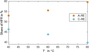
Figure 11. Share of anode and cathode HFR over temperature.
Download figure:
Standard image High-resolution imageFigure 12 shows the results from fitting HFR values (cell, A-RE, and C-RE) at three different temperatures to Eqs. 13–15. Fitting is carried out with a Matlab® solver for nonlinear least-squares problems (lsqnonlin) with a trust-region-reflective algorithm. A global search is used with a multistart object set to 100.
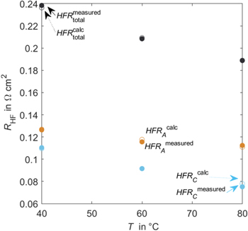
Figure 12. Measured Ohmic resistance for full cell and half-cells over temperatures, theoretical values.
Download figure:
Standard image High-resolution imageTheoretical data meets the measured values. The calculated parameters result in an ionic membrane conductivity of 1.5 S cm−1 and a symmetry factor of 0.34. literature values for the ionic membrane conductivity are reported to be 2.29 S cm−1. 32 The value calculated here results in a slightly lower conductivity, but it also accounts for variations in membrane thickness. The membrane thickness used in the present calculation is valid for dry Nafion™. In operando thickness is expected to be larger due to swelling. The calculated symmetry factor is smaller than 0.5. This indicates that the potential is shifted more toward the anode side. In terms of misalignment, the cathode CL would be smaller.
The fitted anodic constant resistance contribution is 0.07 Ω cm2. For the cathodic constant resistance contribution, a value of 0 Ω cm2 is fitted. The anodic temperature invariant resistance is significant, accounting for almost half the total anodic resistance at 80 °C. The value for the cathode side is calculated to be zero. However, the PTL, CL, and contact resistance cannot be zero. That indicates that the fitted parameters are not consistent with reality. As a possible reason, the membrane thickness may change with temperature due to different swelling behavior. That would affect the symmetry factor. The model would need to be extended outside the scope of this work.
Compression effect on the HFR share
Another way to change the HFR share is by changing the compression of the cell. Figure 13 shows the share of anode and cathode HFR over cell compression. Absolute values can be found in Table S4 in the SI. HFR is measured at 1 A cm−2. The anode-to-RE HFR is always larger. Both values converge with more extensive compression. Larger cell compression can lead to better contact between different layers and better catalyst utilization for a certain range. Moreover, the membrane thickness will shrink with higher cell compression. However, there is no physical description of the compression dependence for the different resistance contributions. Therefore, no fitting is carried out. Anode and cathode HFR values convergeing with compression can have two reasons. 1) the symmetry factor itself is affected and is shifted closer to 0.5 and 2) anode and cathode contact resistances behave differently with compression. For 2), the observed behavior would show an anodic contact resistance that can be significantly improved with higher compression.
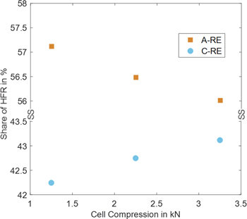
Figure 13. Share of Anode and Cathode HFR from full cell at different cell compression levels.
Download figure:
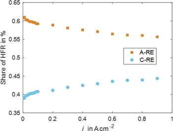
Standard image High-resolution imageCurrent density effect on the HFR share
Hitherto, HFR has been analyzed at the current density of 1 A cm−2. However, the temperature field is expected to change at varying current densities. Since the temperature was shown to impact the anodic and cathodic HFR values, a closer look at their behavior over current density is carried out.
Figure 14 shows the share of anode and cathode HFR over current density at 60 °C. Absolute values for anode, cathode, and full cell HFR and different temperatures over current density can be seen in Fig. S4 in the SI. Material corresponds to numbers 15 in Table S1 in the SI. It can be observed that the anode share slightly decreases with higher current density. The cathode share behaves oppositely, showing a steady increase. The increase can be observed at the absolute full cell level, too.
Figure 14. Share of Anode and Cathode HFR from full cell over current density.
Download figure:
Standard image High-resolution image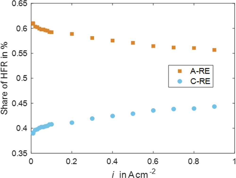
The reaction front within the CL is known to change over current density. 33 Depending on numerous factors (proton and electron conductivity, kinetic parameters, structural parameters, amongst others), the reaction occurs at different locations over the trough-plane axes of the CL. Especially when unequal kinetic regions are considered for the half-cell reactions in a cell (e.g. logarithmic Tafel kinetics vs linear, fast kinetics) the reaction front will shift differently in the anode compared to the cathode CL over current density. This behavior could be the present case where the sluggish reaction at the anode side might shift towards the membrane. This goes hand in hand with more significant effective ohmic resistance for the cathode and smaller for the anode with a larger current density.
Summary and Conclusions
A DHE reference setup has successfully been adapted from fuel cell to electrolysis applications. It is integrated into a standardized test cell manufactured by Fraunhofer ISE. A total of 119 experiments verify the RE's functionality and specify its uncertainty. Information about half-cell potentials and HFR values can be accessed at a current density range of up to 1 A cm−2. This information is used to measure OER and HER kinetic parameters. The Tafel slope for OER attained values around 42 mV dec−1 and an exchange current density of around 1.2⋅10−8 A cm−2. HER kinetic analysis resulted in a linear approximation with an exchange current density of 0.269 A cm−2.
Additionally, the collected half-cell HFR results confirmed that misalignment is nearly always present in measurements. Therefore, half-cell EIS data is necessary for HFR-corrected half-cell voltages. Assuming to measure half of the membrane resistance would lead to erroneous results. Further misalignment and loss breakdown analysis is proposed by analyzing trends over temperature, cell compression, or current density. However, these have limitations regarding the discovery of the exact misalignment.
Future work includes an extended model for the temperature dependence of ohmic resistance. Moreover, the RE setup is currently in use for a 1,000 h long-term degradation test for PEMWE.
Acknowledgments
The authors gratefully acknowledge the financial support by the Federal Ministry of Economic Affairs and Climate Action of Germany in the framework of HoKaWe (03EI3029B), Ray Bi, for ink preparation for Pt patches and support in spray coating, Yu Pei for fruitful discussion on reference electrodes (both Department of Chemical and Biological Engineering at the Clean Energy Research Centre, University of British Columbia), Jonathan Brandt, Institute of Electric Power Systems, LUH, for knowledge and support in global optimizations, Grace Lindquist, Department of Chemistry and Biochemistry, University of Oregon, for fruitful discussion on reference electrode implementations. This research was partly funded by a doctoral scholarship from the DAAD-Stiftung to the first author.
Supplementary data (2.5 MB DOCX)