
Abstract
Microphotosynthetic Power Cells (μPSCs) have emerged as a promising bioelectricity generation technology with the potential to meet the low-power application demand in a sustainable, and environmentally friendly manner by leveraging the photosynthetic capabilities of autotrophs. Internal losses connected to the transfer of charges from the photosynthetic organisms to the electron acceptor (anode electrode), however, continue to pose a serious challenge to the efficiency of the system. Over the years, many different designs have been reported. The potential of boosting power density with device miniaturization is discussed in this study as it provides a crucial pathway for performance enhancement.
Export citation and abstract BibTeX RIS

This is an open access article distributed under the terms of the Creative Commons Attribution 4.0 License (CC BY, http://creativecommons.org/licenses/by/4.0/), which permits unrestricted reuse of the work in any medium, provided the original work is properly cited.
Photosynthesis, the world's oldest energy conversion process, relies on light energy and water, the most abundant resources available, to keep green life going. 1,2 During photosynthesis, CO2 is reduced into chemical energy to fuel cellular activities, giving off oxygen as a byproduct. 3 Biological electrochemical systems (BECs), like the Microbial Fuel Cell (MFC) 4–6 and the μPSC 7–9 (also referred to as biophotovoltaic cell (BVC), 10 microphotosynthetic electrochemical cell (μPEC), 11 and microfluidic bio-solar panel 12 in the literature) have emerged a promising alternative to fossil combustibles to meet the rising global energy demand. The μPSC is characterized by its use of living organisms, precisely oxygenic photosynthetic organisms, as "natural" solar panels - cheap, self-regenerating, and readily available - for electricity generation; unlike its counterpart which uses heterotrophic bacteria as biocatalysts - to catalyze the oxidation of organic substrates (e.g., biomass, waste-water, etc.). Currently, the conversion efficiency of the latter is higher, 13,14 but the organic fuels it relies on are not inexhaustible, as opposed to the former's energy source—the Sun—which is near-infinite and widely available. μPSCs are currently unable to convert the photosynthetic microorganisms' high energy conversion efficiency into power output. 15 As a result, extensive research from both biological and engineering perspectives is required to determine what the limiting factors are. The working principles of the μPSC and the MFC are illustrated in Figs. 1a and 1b respectively.
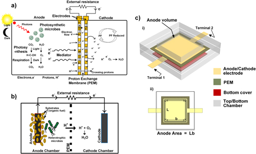
Figure 1. Schematic describing the operating principle of (a) a Microphotosynthetic power cell (μPSC), and (b) a microbial fuel cell (MFC). (c) i A descriptive 3D model of the μPSC, ii Top view showing the anode work area. The fabrication process is described in Ref. 16.
Download figure:
Standard image High-resolution imageThe BECs have over the years transitioned through a series of model changes geared toward performance enhancement. The more established MFCs 13,17–22 have received a lot of attention and have played an important role in the optimization of the rather nascent μPSC. 2,7,12,23,24 Miniaturization in a general sense offers huge potential for improved precision and throughput in cell studies. It has found huge usefulness in microfluidic cell studies, which allows for small culture volume, as well as single-cell studies—useful in identifying salient genetical characteristics which could, in turn, be used to direct the development of certain efficient cell lines, 25–27 in bioelement detection, 27–29 cell separation, 30 and so on. Similarly, in the context of bioelectricity generation with PSCs, miniaturization reduces the distance charges released by the donors (photosynthetic organisms) have to travel to reach the acceptor (the anode electrode), minimizing resistive losses in the anolyte. 4
Working of The μPSC
The typical architecture and working of the μPSC are described in Fig. 1a. It comprises two chambers, an anode chamber—containing the anode electrode and the photosynthetic microorganisms (e.g., algae, cyanobacteria, etc.), and a cathode chamber, comprising the cathode electrode. Both chambers are separated by a unit comprising a proton exchange membrane (PEM) sandwiched by the anode and cathode electrode, often referred to as membrane electrode assembly (MEA). Electron transfer from the microbes to the anode electrode can be through direct cell contact (cytochrome based), 31,32 direct nanowire contacts, 33 or mediator supported. 8,16 The electron travels from the anodic electrode via an external circuit (as seen illustrated in the figure) to produce electricity as they continue to the cathode. The protons, on the other hand, transit through the PEM (commonly made of Nafion - sulfonated tetrafluoroethylene-based fluoropolymer) to the Cathode compartment. The PEM at the same time prevents the cross-flow of the electrons. The cathodic reaction is often a function of the type of electron acceptor used; 8,34,35 nevertheless, in all, the diffused protons recombine with oxygen in the cathode section (i.e. the electron donor is re-oxidized, and oxygen gets reduced) to produce water, carbon dioxide, and energy. The chemical equation of photosynthesis and respiration are as follows:
Photosynthesis:

Light-dependent
Respiration
Light-independent

Algae have been used extensively in the μPSCs for their characteristic photosynthetic nature, and more so, for their ability to grow fast and as well survive adverse weather conditions. Species like Chlamydomonas reinhardtii, Dunaliella tertioelecta, and Chlorella vulgaris have garnered the most attention, according to the literature. 8,16,34
Applicability
The μPSC is applicable in various ultra-low and low-power (0.1–100 mW) applications. For instance, in a very recent study, a single unit of the μPSC was shown capable of powering a microprocessor (Arm Cortex M0+) for six months. 36 There is another study that showed its utility in an internet of things (IoT) humidity sensor (0.18 mV), 37 explorable in remote weather monitoring. The μPSC can also be used to power IoT sensors in autonomous vehicles, and ultrasonic sensors, given their low power requirements (0.2–80 mW). 37–39 More so, a combination of two or more PSC devices in parallel or series arrays could be used to meet higher power demands. For further details on the application potentials of the μPSC technology, readers can refer to our previous works. 9,40
Current status
While still in its early stages, the μPSC holds a lot of potential for a carbon-negative power supply. Based on the literature, the μ-PSC designs can produce open-circuit voltages in the range of 100–993 mV and short circuit currents in hundreds of μA, current densities in the range of 0.2–3000 mA m−2, and power densities ranging from 0.0004 to 715 mW m−2. 8,16,23,34,41–43 Thus far, the maximum power reported of a single μPSC device reported is 715 mW m−2, 42 which involved the use of gold nanoparticles in the anode chamber to enhance photon absorption as well as electron transport from the microorganism (algae - Chlamydomonas reinhardtii) to the anode surface. Although this represents a significant advancement for micro-biological solar cells generally, considerable work remains to be done to fulfill commercial requirements. For more information on the development of the μPSC technology, readers are referred to Refs. 4, 8, 42–45.
Performance measurement
Some common parameters for quantifying the performance of the μPSC include, open-circuit voltage (OCV), current density (CD), power (P), power density (PD), polarization and power curves, quantum yield, and Coulombic efficiency,  5,24
The OCV quantifies is the maximum potential obtainable from the cell, measured from the terminals of the cell in the absence of an external load or electric current - as opposed to the maximum potential attainable in the cell (i.e., the ideal voltage). The ideal voltage (~1.2 V in an air-cathode MFC: 0.805 V from the cathode and −0.42 V from the anode
5
), which corresponds to the cell emf (
5,24
The OCV quantifies is the maximum potential obtainable from the cell, measured from the terminals of the cell in the absence of an external load or electric current - as opposed to the maximum potential attainable in the cell (i.e., the ideal voltage). The ideal voltage (~1.2 V in an air-cathode MFC: 0.805 V from the cathode and −0.42 V from the anode
5
), which corresponds to the cell emf ( )/Nernst reversible voltage (NRV), comes in the absence of internal losses (such as ohmic, concentration and activation losses). The current divided by the total electrode area gives the CD. It reflects the inherent rates of charge transfer between analytes and the electrode, providing insights into the structure and interrelation of the analyte and the current collector. Measured cell voltage
  is often a linear function of the current, and simply described as
  where
where  is the summation of all internal losses of the μ-PSC, proportional to the system's internal resistance
  and generated current
  Power is estimated
  the voltage is taken across a fixed external resistor
  while the current
  is estimated from
  Hence, power is estimated normally as
  The PD is useful for comparing the power yield of different systems. Power is normalized to a characteristic feature of the generating system, usually the effective anode surface area, as it is where the biological reactions take place.
4,8,45
Further discussions on the PD will be presented in the next section. The Coulombic efficiency basically describes the efficiency of the system in harnessing electrons from the photosynthetic organisms; in terms of the ratio of electrons recovered to the amount available in the system if all the microorganisms produced current.
46
The PD is useful for comparing the power yield of different systems. Power is normalized to a characteristic feature of the generating system, usually the effective anode surface area, as it is where the biological reactions take place.
4,8,45
Further discussions on the PD will be presented in the next section. The Coulombic efficiency basically describes the efficiency of the system in harnessing electrons from the photosynthetic organisms; in terms of the ratio of electrons recovered to the amount available in the system if all the microorganisms produced current.
46
Power density, a key factor for performance comparison and optimization
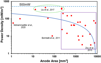
The PD is basically a measure of the power generated by a device divided by the size of the device. At the macrolevel, it presents a straightforward approach to compare any power product towards efficiency enhancement as well as for thermal considerations. In the BES settings, it quantifies the performance in terms of power output per electrode size (active surface area, in particular), with a common unit of measurement of PD in milliwatts per meter square (mA/m2). Hence, one simple approach to increasing PD is reducing component size (that is, miniaturization). It principally provides the benefit of higher surface-to-volume ratio, hence, heat—a critical efficiency parameter of any electrical/mechanical system—is dissipated faster than stored; and a system that releases energy quickly can also recharge quickly. In addition to this, there is also the advantage of component integration. Energy supply from components small enough to fit inside a cell phone or camera flash, for instance, and sufficient to power the device makes an ideal high-power density system. Similarly, in BECs, in addition to the benefits of reduced anolyte volume and shorter charge transport length scales, the thermal performance of the system is enhanced by the dominance of heat dissipation over heat storage, resulting in greater efficiency, measurable through the PD. This is highlighted by our assessment of the several types of PSC designs that have been reported during the past two decades, which is summarized in Fig. 2. For ease of classification and a fair comparative basis, devices that implemented external performance boosters like gold or silver nanoparticles, as in Refs. 42, 47, and the like are left out.
Figure 2. The trend of Power Density increase with decreasing component size in the last two decades (Details in Appendix).
Download figure:
Standard image High-resolution image
As earlier indicated, the main goal of this work is to examine the relationship between size reduction and power output from the several different uPSC designs that have been reported during the past two decades. In essence, miniaturization enhances the physical proximity of the biocatalyst organisms to the anode surface, shortening the length scale of charge transfer and reducing resistive loss in the electrolyte as a result. By contrast, in macro BECs, where charges must travel longer distances, factors including ohmic polarization, reaction kinetics, and concentration (mass transport) polarization are known to have significant limiting impacts on power outputs. 4,22
Figure 2 presents an overview of the Power Densities of intrinsic μPSCs (that is, with no external energy booster) from recent literature data (details in supplementary Table A). While other factors such as biocatalyst agents' photosynthetic capacity, electrode material, light intensity and so on all play a role in the device's electrical output, increasing the surface-to-volume ratio of the working unit through miniaturization offers great prospects for optimizing the overall performance of the μPSC technology. There are also instances where extrinsic energy inputs have been used to obtain significant power density boosts. 42,43,48 Nevertheless, a comprehensive review of the literature, summarized in Fig. 2, reveals a noteworthy connection between miniaturization (measured in terms of anode surface area) and gains in power density. Clearly, most of the reported works have shown lower power density with higher anode area (highlighted by the rectangular box in the figure). The green ellipse, on the other hand, demonstrates the higher power densities amongst all the listed μPSCs. The studies, in other words, demonstrated relatively optimum anode surface areas. This in all emphasizes the need for optimal anode area design in order to increase the PSC's power density.
Subsequently, to push the μPSC technology to levels suitable for real-world applications, two or more units of the μPSC device can be arrayed in diverse configurations to obtain an optimized total operating voltage and current, sufficient to meet the demands of low-power devices. 49 The various array configurations and their power output have been investigated and it was suggested to design the array configurations based on the power requirement. To this end, the beauty of miniaturization, which offers a huge promise of power enhancement through optimal work area design and the combining of many small units, becomes even more tangible in our quest to push green energy to the greatest heights.
Challenges and Future Needs
Even though the μPSC technology is capable of producing power in both light and dark conditions, quite a few intrinsic and extrinsic limiting factors still abound, posing an impediment to its commercial application. Efforts and investment are, however, increasingly on the rise towards resolving these issues and achieving reliable operational cost-effective performance. 10,16,42,50–52 The various issues relating to design, fabrication complexity, manufacturing cost, modeling, materials, and operating conditions are described in our prior study. 9 We have also, in another study, discussed the enormous application potential of the technology, in the effort to reduce our dependence on fossil combustibles which continually pose a threat to our ecosystem. 40 Although the idea of improving power density by lowering component sizes is very practical , there is a limit to the strategy because size is also a key factor in the actual component value. As a result, more research is needed to establish the limits and bounds of miniaturization, as well as component arrays (how small is too small, and how large of an array would be most efficient) -from the perspective of overall system efficiency, and to establish a guide for making informed tradeoffs toward relevant design optimization.
Summary
The eco-friendly μPSC technology thus far is capable of power densities just in 100 s of  A way to improve power output is by increasing interaction between the electron-donating photosynthetic organisms and the electron-accepting electrode through miniaturization. As power density becomes a more important factor in comparing power products (dc-dc converters, power amplifiers, etc.), power circuit design and supply, and others, future μPSC studies need to closely look at minimizing internal losses, enhancing thermal performance, as well as increasing integration for efficient sustainable performance in commercial applications.
Acknowledgments
The authors acknowledge the financial support of M.P. from the Natural Sciences and Engineering Research Council of Canada (NSERC), New Frontiers Research Fund, and Concordia Research Chair.
Appendix
Table A·I.
Table A·I. List of photosynthetic power cell studies in recent years (in the order of increasing anodic electrode area).
| Study (First Author, Date) | Device name | Active Anode Area [mm2] | Active Anode Volume [μl] | Power Density [mW m−2] | Mechanism for electron export (Anode) | Photosynthetic organism |
|---|---|---|---|---|---|---|
| Bombelli, 2014 10 | Bio-photovoltaics | 0.03 | 0.4 | 105 | Free | Synechocystis sp. PCC 6803 |
| Saar, 2018 50 | Bio-voltaic device | 0.08 | 1000 | 300 | K3[Fe (CN)6] | Synechocystis sp. PCC6803 cells |
| Saar, 2018 50 | Bio-voltiac device | 0.08 | 1000 | 500 | K3[Fe (CN)6] | Synechocystis sp. PCC6803 -mutant cells |
| Torabi, 2021 53 | Biophotovoltaics | 0.9 | 1.8 × 10⁶ | 220.7 | Free | Thermosynechococcus elongatus BP-1 |
| Mohammadifar, 2020 54 | Bio solar cell | 1.2 | 10 | 56.4 | Free | Synechocystis sp. PCC6803 |
| Sekar, 2014 55 | Photo-bioelectrochemical cells | 2.5 | n/a | 100 | 1,4-benzoquinone | Nostoc sp. |
| Masi, 2020 56 | Biofuel cell | 13 | 50 | 340 | Free | Thykalod membranes of Spnach plants |
| Yoon, 2014 57 | Microbial Solar Sell | 28 | 57 | 0.0709 | Cyanobacteria, Synechocystis, PCC 6803 | |
| Liu, 2017 58 | Micro biological solar cell | 38.5 | 90 | 438 | Free | Synechocystis sp. PCC 6803 |
| Chiao, 2006 17 | Photosynthetic electrochemical cell (μPEC) | 50 | 4.3 | 0.0004 | Methylene | Blue Anabaena sp. |
| Liu, 2019 59 | Biological solar cell | 50.3 | 100 | 107 | Free | Synechocystis sp. PCC6803, Shewanella oneidensis MR-1 |
| Bombelli, 2011 7 | Bio-photovoltaics | 80 | 150 | 10.2 | [Fe (CN)]3− | Synechocystis sp. PCC 6803 |
| Senthiljumar, 2018 60 | Biophotovoltaics | 100 | 10000 | 0.036 | Free | Chlorella vulgaris |
| Thong, 2021 61 | Biophotovoltaics | 200 | n/a | 0.04 | Free | Chlorella vulgaris |
| Shahparnia, 2015 8 | Photosynthetic power cell | 220 | 2000 | 362.2 | Methylene Blue | chlamydomonas reinhardtii |
| Ramanan, 2015 16 | Photosynthetic power cell | 220 | 2000 | 400 | Methylene Blue | chlamydomonas reinhardtii |
| Thorne, 2011 62 | Photo-microbial fuel cell | 230 | 2300 | 24 | [Fe (CN)]3− | Chlorella vulgaris |
| Saper, 2018 63 | Bio-electrophotochemical cell | 254 | 5 | 200.4 | Free | Synechocystis sp. PCC6803 cells |
| Schneider, 2016 64 | Photo- microbial cell fuel | 390 | 3100 | 14.5 | Fe (CN)3− | C. vulgaris |
| Inglesby, 2013 65 | Photosynthetic microbial fuel cell | 400 | 4000 | 0.0248 | Free | Mixed photosynthetic biofil consortia |
| Firoozabadi, 2021 66 | Biophotovoltaics | 400 | 880 | 148.27 | Free | Synechocystis sp. PCC6803 |
| Cevik, 2020 67 | Bio-electrochemical fuel cell | 625 | n/a | 42.2 | Free | Green alga Choricystis sp. |
| Zhu, 2019 68 | Bio-photovoltaic cell | 625 | 1.4 × 10⁵ | 150 | Free | Synechococcus elongatus UTEX 2973 |
| Gonzalez, 2015 69 | Photosynthetic microbial fuel cell | 800 | 8 × 10⁵ | 42.98 | Activated sludge | |
| Bombelli, 2022 36 | Aluminium Biophotovoltaic System | 860 | 14400 | 42 | Free | Synechocystis sp. PCC 6803 |
| Bombelli, 2022 36 | Aluminium Biophotovoltaic System | 1020 | n/a | 0.4 | Free | Synechocystis sp. PCC 6803 |
| Siu, 2008 19 | Photosynthetic Electrochemical cell | 1200 | 15.6 | 0.0004 | Methylene Blue | Anabaena sp. (Suspension) |
| Ng, 2014 70 | Bio-photovoltaics | 1225 | n/a | 0.27 | Free | Chlorella sp. (UMACC313) |
| Ng, 2018 71 | Bio-photovoltaic cell | 1225 | 5 × 10⁵ | 0.32 | Free | Synechococcus elongatus (UMACC 105) |
| Ng, 2018 71 | Bio-photovoltaic cell | 1225 | 5 × 10⁵ | 0.538 | Free | Synechococcus elongatus (UMACC 105) |
| Sawa, 2017 72 | Biophotovoltaics | 1250 | n/a | 0.38 | Free | Chlorella sp. UMACC 313 |
| Gouveia, 2014 73 | Photosynthetic alga microbial fuel cell | 1260 | 50000 | 62.7 | Bacterial Consortium | |
| McCormick, 2011 15 | Bio-photovoltaic cell | 1300 | 12600 | 10 | Free | Synechococcus sp. WH 5701 |
| Bradley, 2013 74 | Bio-photovoltaic cell | 1300 | 31500 | 0.2 | Free | Synechocystis TM |
| Luimstra, 2014 75 | Photosynthetic microbial fuel cell | 1400 | 70000 | 6 | Free | Pauschulzia pseudovolvox |
| Madiraju, 2012 76 | Microbial fuel cell | 1500 | 60000 | 0.3 | Free | Synechocystis sp. PCC 6803 |
| Wu, 2014 77 | Photo-microbial fuel cell | 1600 | 1.25 × 10⁵ | 64.2 | Free | Desmodesmussp. A8 |
| Bombelli, 2012 78 | Bio-photovoltaics | 2000 | 20000 | 0.02 | Free | Oscillatoria limnetica |
| Nishio, 2010 79 | Photo-bioreactor | 2000 | n/a | 3.2 | Free | Green hot spring microbial mat (Biofilm) |
| Gunaseelan, 2021 80 | Biophotovoltaics | 2000 | 80000 | 275 | Free | Effective Mirobes(EM) and Anaeroubic sludge bank reactor (UASB) |