
Abstract
To date, several high-performing anion exchange membrane fuel cells (AEMFCs) have been demonstrated, but most these studies have focused on Pt containing cathodes with high loadings. Here, we explore and compare the performance and perform electrochemical diagnostics on three leading AEMFC cathode electrocatalysts: Pt/C, Ag/C, and Fe–N–C with electrodes that have been processed with either powder or dispersion-based ionomers using perfluorinated anion exchange polymers. Pt/C had the highest performance but also showed a strong dependence on ionomer type, with powder ionomer exhibiting much higher performance. These results were consistent with the observations for Ag/C but did not hold for the Fe–N–C catalyst where almost no change was observed between powder and dispersion-based ionomers. This is the first-time the impact of powder and dispersion ionomer with different classes of cathode electrocatalysts on the fuel cell performance have been compared, and the results have strong implications for the ability to achieve high performance at low loadings and for better understanding catalyst-ionomer interactions within AEMFCs.
Export citation and abstract BibTeX RIS

This is an open access article distributed under the terms of the Creative Commons Attribution 4.0 License (CC BY, http://creativecommons.org/licenses/by/4.0/), which permits unrestricted reuse of the work in any medium, provided the original work is properly cited.
Fuel cells are promising portable power source due to their advantage of low operating temperature, minimal emissions, and rapid startup. 1,2 Proton exchange membrane (PEM) fuel cell have achieved enormous progress after decades of development and now stand on the brink of the large-scale commercialization. 1,3,4 However, a remaining challenge for PEM fuel cells is materials compatibility under highly acidic conditions such that anion exchange membrane fuel cells (AEMFCs) are of interest to potentially reduce or remove platinum group metal (PGM) requirements. 5–7
Pt is widely used as the catalyst of choice in the alkaline fuel cell cathodes. 8 This is likely because of a desire to achieve high peak power density and/or to improve performance and durability. In many cases, the choice of Pt may also be to probe the AEM and compare it to other AEMs under similar conditions. 9 While these approaches are reasonable, a major gap exists in trying to specifically probe the ability to reduce or remove PGM loadings.
As an alternative to Pt, low cost and abundance make Ag a promising alternative electrocatalyst. Ag catalyst for ORR in alkaline media has been widely investigated with different Ag crystal phases and with various support materials. 10 Although, Ag is less active than Pt, Ag does have reasonable activity under alkaline conditions. 11 In recent publications, Ag/C as cathode catalyst has been demonstrated with more than 1 W cm−2 power density in alkaline fuel cell and hundreds of hours of stability. 12–15
PGM-free catalysts have been under investigation for some time for PEM fuel cells and are therefore available to study in AEMFCs. 16,17 The most common type of PGM-free catalyst is nitrogen-doped carbons with earth abundant metal atoms like iron, Fe–N–C. Most of the work on PGM-free catalysts has been done in acid media for PEMFCs where they have shown good kinetic activity. 16,18 However, durability issues still remain a concern. 19 The operating condition of AEMFCs system offer a potential advantage as materials compatibility under highly basic conditions may offer benefits over highly acidic conditions while also possibly offering kinetic advantages. 11,20,21
Pt/C, Ag/C and Fe–N–C represent 3 model catalysts to explore for their ability to be employed as AEMFC cathodes. In fabricating fuel cell electrodes, catalyst is incorporated with ionomer in the catalyst layer, where the ionomer provides ionic pathways for ion flow to and from reaction sits. 22 Most fuel cells fabricate electrodes using a conventional dispersed ionomer. This has been the technology that has been developed and deployed in PEM fuel cells and is the default for most electrode fabrication. Since 2014, Varcoe et al. developed solid powder type polymers and with the help of Mustain et al. developed high performing MEAs based on powder-based ionomers. 23–25 With powder ionomer, AEMFC peak power density has already achieved over 3 W·cm−2. 26 However, there have not yet been investigations comparing dispersion and solid powder ionomer based electrodes with same polymer used in the electrodes. Our access to novel polymers and experience in powder-based electrodes, enables our team to perform these studies and evaluate the impact of ionomer type on cathode properties and performance. Beyond fuel cell performance, diagnostic tools including high frequency resistance, cyclic voltammetry, and impedance spectroscopy have also been applied. The results provide insight into the differences between different catalysts/ionomer types in terms of catalyst-ionomer interactions and water management impact. The findings are important to achieving higher performing, more durable AEMFCs with reduced PGM content.
Experimental
Membrane and ionomer preparation
Synthesis of the sulfonamide-linked alkyl ammonium perfluorinated anion exchange membrane (PF AEM) Gen 2 polymer was performed as previous reported by Park et al. 27 It will be used as both membrane and ionomer material to fabricate membrane electrode assemblies (MEAs) for fuel cell testing.
Gas diffusion electrode (GDE) fabrication
Dispersion and solid types of ionomers were used as binder in this work, both are based on PF AEM polymer. 10wt.% PF AEM dispersion ionomer solution was prepared from deionized (DI) water (resistivity of 18.2 MΩcm) and 2-propanol (Sigma-Aldrich, suitable for HPLC, 99.9%) dispersion with 1:1 volume ratio. Catalyst ink was prepared by mixing Pt/C (Alfa Aesar, Platinum, nominally 40% on carbon black), DI water, 2-propanol and ionomer solution to make sure the ionomer loading in the catalyst layer is 20 wt.%. With similar ink composition, the PF AEM solid ionomer was ground for 10 min before adding into ink solution. 23 The catalyst mixture was then tip sonicated for 15 s, followed by ice bath sonicating for 30 min. The gas diffusion electrode was fabricated by hand spraying catalyst ink onto a gas diffusion layer (Toray paper TGP-H-060 with 5% PTFE wetproofed). The platinum catalyst loading was verified by X-ray fluorescence spectrometer (HELMUT FISCHER GRUPPE, Fluorescence spectrometer X-ray XDV-SDD) and the Pt loading was found to be 0.5 mg·cm−2.
The MEAs with Ag/C (FC Catalyst, 40% Silver supported on Vulcan XC-72), PtRu/C (Alfa Aesar, Platinum, nominally 40%, Ruthenium, nominally 20% on carbon black) and Fe–N–C (PMF-011904, Pajarito Powder LLC) catalyst fabrication methods were same as Pt/C. The Ag loading in the cathode side was 0.35 mg·cm−2. Non-PGM catalyst loading in the MEA was applied with 0.6 mg·cm−2. All the anode MEAs were applied with PtRu/C mixed with solid ionomer and PGM loading was 0.8 mg·cm−2. The Ag loading could have potentially been made higher, but we experienced difficulties with the powder-based electrodes at higher loading levels and feel that 0.35 mg·cm−2 was sufficiently high for the study presented.
MEA assembly and fuel cell testing
Before fuel cell assembly, GDEs and a PF AEM Gen 2 membrane were exchanged in 1 M KOH solution over 4 h replacing with new base solution every hour. The membrane was sandwiched between two GDLs and pressed together, secured in 5 cm2 Fuel Cell Technologies hardware between two single serpentine flow graphite plates using PTFE gaskets to obtain a 25% compression of the GDEs with torque applied in incremental steps to 40 in-lb.
A modified 890E Scribner Fuel cell Testing Station was used for fuel cell performance evaluation. The cell temperature, anode and cathode dew points were set at 70 °C initially. The H2 and N2 was flown through anode and cathode electrodes at 1000 ml min−1 until achieved desired cell temperatures and electrodes dew point. Then the N2 was switched to O2 and absolute pressure was set at 131 kPa. After OCV stabilized, a constant voltage of 0.5 V was applied for the cell break-in process. Break-in always took around 30 min to observe a constant current density. The polarization curves were measured by sweeping voltage from OCV to 0.1 V at a scan rate of 10 mVs−1. Mass transport overpotentials calculation method are reported in our previous paper. 9
Results and Discussion
Figure 1 provides a summary of the fuel cell performance (a–c), power density (d–f) cell kinetics (g–i), and mass transfer overpotential (j–l) with different catalysts (Pt/C, Ag/C, and Fe–N–C) for both powder and dispersion ionomers. By plotting data in this manner, we can more easily see trends for the three different catalysts investigated as well as trends between different ionomer type. Fuel cell performance, cell voltage and high frequency resistance (HFR) as a function of current density, is shown in Figs. 1a–1c and power density as a function of current density is shown in Figs. 1d–1f. These data reveal significant differences between samples based on both catalyst and ionomer type. The highest fuel cell performance was obtained with Pt/C catalyst reaching up to 1.2 W·cm−2 peak power density with powder ionomer. However, a significant difference of performance between ionomer types was observed. The peak power density obtained with dispersion based ionomer was only 0.65 W·cm2, approximately half that obtained using powder ionomer. The MEA with powder ionomer also exhibited a much lower high frequency resistance (HFR). Similar trends in performance and HFR were also observed for the Ag/C MEA. The powder ionomer MEA reached a peak power density of 0.52 W·cm−2, again also double that of the dispersion ionomer. The HFR of the Ag/C electrode with dispersion ionomer was also much higher than the powder ionomer. These results stand in stark contrast to the observations for MEAs with Fe–N–C catalyst where Fe–N–C MEAs show essentially no performance or HFR impact regardless of ionomer type until high current densities where the dispersion ionomer shows sharper mass transport limitations.
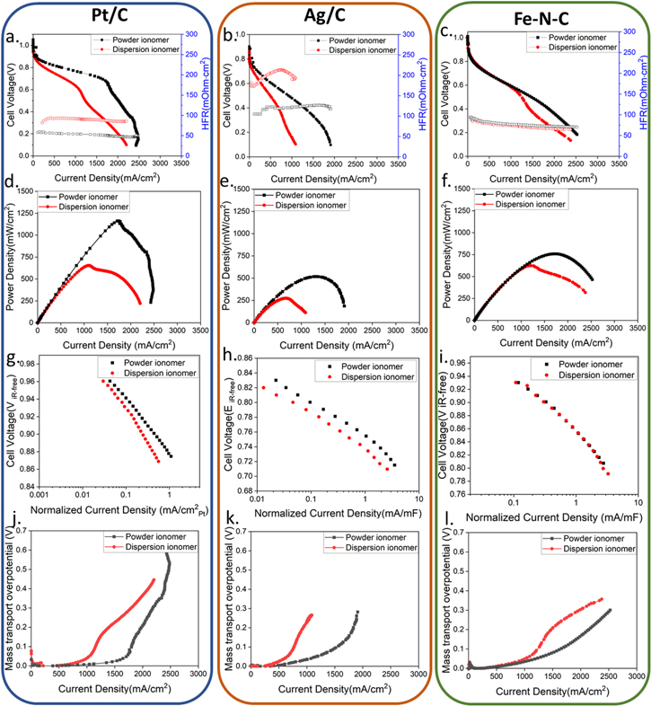
Figure 1. Electrochemical evaluation with Pt/C, Ag/C and Fe–N–C as cathode catalyst applied with powder ionomer and dispersion ionomer. (a)–(c) Cell performance under 100%RH, 70 °C cell temperature and 131 kPaa (d)–(f) power density as function of current density (g)–(i) kinetic data (j)–(l) mass transport overpotential.
Download figure:
Standard image High-resolution imageThe changes in HFR account for only a small fraction of the observed performance differences in the Pt/C and Ag/C MEAs, suggesting that other factors beyond ohmic (kinetic or mass transfer) losses account for most of the observed performance differences. The large changes in HFR are surprising for only a processing change of the cathode. As all the anode electrodes and membranes were prepared identically, and from our extensive work on these systems we know our reproducibility from cell to cell is high, the change in HFR is attributed to the impact that the cathode has on water management in the cell. Specifically, the higher HFR indicates the Pt/C and Ag/C MEAs with dispersion ionomer were at a lower level of hydration compared to the powder ionomer electrode. The relative values of the HFR and their trends with current density provide additional insight into the impact of different cathodes on hydration level. Specifically, Ag/C MEAs showed much higher HFR than Pt/C or Fe–N–C MEAs. Additionally, these Ag/C MEAs showed a trend towards increasing HFR with increasing current density, at low current density reaching a maximum and then decreasing with further increasing current density. In contrast to the Pt/C and Fe–N–C MEAs that showed a general trend of decreasing HFR with increasing current density. These results show that processing of ionomer in the cathode can have a major impact on water balance in the cell for Pt/C or Ag/C electrodes, while essentially having almost no impact on Fe–N–C catalysts, indicating that both the nature of catalyst and the type of ionomer employed can be critical variables for cell optimization.
To probe the impact of catalyst and ionomer on kinetics, the kinetic current densities were recorded and are shown in Figs. 1g–1i. For both Pt/C and Ag/C MEAs, dispersion ionomer exhibited significantly lower kinetic performance than the powder ionomer. Because the same catalysts and catalyst loading was used for these studies, a similar kinetic performance might have been expected. This assumes that each catalyst has similar access, and that catalyst performance is not impacted by the ionomer. These results clearly show that different ionomer types can directly impact kinetic performance. Again, the Fe–C–N MEA showed no dependence on kinetics between the powder and dispersion ionomers, shown in Fig. 1i.
Mass transport overpotential as a function of current density has also been calculated and is shown in Figs. 1j–1l. For all catalysts studied, the powder ionomer MEAs demonstrated lower mass transport overpotential losses compared to dispersion ionomer cathodes. At low current density, the mass transport overpotential losses were nearly identical, but for the Pt/C and Ag/C catalysts the current density at which mass transport losses started to increase were lower for the dispersion-based cathodes. Although the qualitative shape of the dispersion and powder-based cathodes had similarities in these cases. For the Fe–N–C catalyst the dispersion-based cathodes showed slightly a lower current density onset for mass transport losses, but the qualitative shape of the two curves was also different with this gap slightly decreasing at further increasing current density. While it is clear that there are impacts on mass transport losses, it is unclear if these are due to anode or cathode effects. Both anode and cathode are potentially susceptible to flooding, and our other data show cathode changes can impact water management within the membrane and at the anode in these systems. Considering the non-PGM catalyst tends to be much more hydrophilic compared with traditional carbon supported PGM catalyst, 28 some of the differences observed may be related to different surface energy considerations of the different catalyst types.
Other aspects of the different cathodes studied were investigated using electrochemical diagnostics. Cyclic voltammograms (CV) were recorded and are presented in Figs. 2a–2c to further probe the impact of different catalysts and ionomers. Consistent with previous findings a significant difference between the powder and dispersion ionomer CVs is apparent for both Pt/C and Ag/C, while CVs for Fe–N–C are essentially identical. The Pt/C cathodes have perhaps the most telling CVs due to the distinct electrochemical features associated with Pt. 29 It is clear the powder ionomer results in sharper Pt features than that with dispersion ionomer. Thus, for both Pt/C and Ag/C, there exist different catalyst/ionomer interactions between powder and dispersion ionomers. For the Fe–N–C catalyst, essentially identical cyclic voltammogram were observed with different ionomer types, indicating that differences in catalyst/ionomer interactions had little impact on Fe–N–C MEAs. These trends are consistent with the fuel cell performance and kinetic responses presented in Figs. 1a–1i.
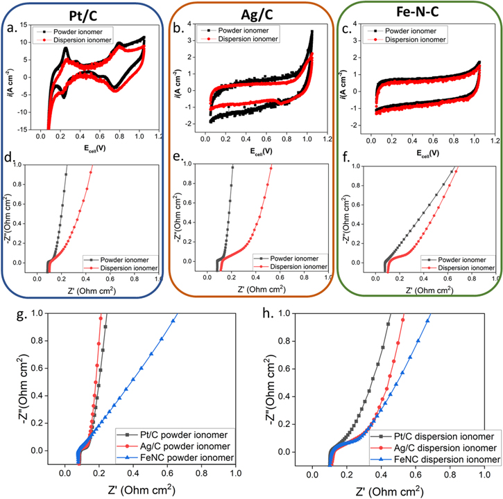
Figure 2. Electrochemical evaluation with Pt/C, Ag/C and Fe–N–C as cathode catalyst applied with powder ionomer and dispersion ionomer. (a)–(c) Cyclic voltammetry data. (d)–(h) Electrochemical Impedance spectroscopy data at OCV under H2/N2.
Download figure:
Standard image High-resolution imageElectrochemical impedance spectroscopy (EIS) data is presented in Figs. 2d–2h. Because essentially identical membranes (within our ability to cast reproducibly, typically within 10% thickness variation) and consistent gas humidification levels were used in all cells, similar high frequency resistance would be expected in the absence of applied current density and was observed in all MEAs. However, the HFR data in Fig. 1 shows significant ranges of HFR were observed for different samples with a strong variation depending on current density in some cases. Operating current density is expected to impact both water management and frequency dependence of real and imaginary contributions to cell impedance. Unfortunately, we did not measure full frequency EIS under operating current densities due to project limitations. Still, it is worthwhile to compare the open circuit EIS data to that of the HFR data obtained under operating conditions.
Figures 2d–2h clearly show almost identical cell resistances, but clear differences in impedance contributions are easily identified. First, for all three catalysts studied Figs. 2d–2f, electrode impedance is significantly larger in the dispersion-based electrodes relative to the powder based electrodes. The powder-based electrodes, Fig. 2g, shows the least electrode impedance for the Pt/C and Ag/C electrodes which have almost identical impedance spectra. The Fe–N–C electrode shows much higher electrode impedance which might be anticipated due to the significantly increased thickness of these electrodes due to the relative density of metal nanoparticle on carbon catalysts relative to PGM-free catalysts. The significant electrode impedance in the dispersion-based electrodes, Fig. 2h, suggest that ion conductivity through the Pt/C and Ag/C electrodes is greatly reduced compared to the powder-based electrodes with the effect being more substantial in the Ag/C electrodes. These data highlight some of the potential limitations of these cathodes in terms of both catalysts employed and ionomer processing employed.
To further study the impact of water balance on these cells with different cathodes, we applied slight humidification changes to the cells and measured cell performance and HFR as reported in Fig. 3. The polarization plots with slight humidity variations indicates that electrode hydration is not only dependent on the catalyst, but also related to ionomer type. For Pt/C and Ag/C catalyst, the electrode with powder ionomer had lower HFR compared with the electrode with dispersion ionomer, and HFR decreased or remained relatively stable with increasing current density for the powder electrode while it increased with current density for the dispersion ionomer. This behavior suggests that the dispersion-based cathode experienced significant dry out within the membrane. This behavior was coupled with lower overall cell current density, which is often associated with anode flooding, but in this case could also be due to less efficient use of the cathode under dry conditions. In most cases, the driest cell conditions resulted in the poorest performance, but in the case of Pt/C powder-based cathode, the driest condition probed resulted in the highest performance of all samples suggesting this cell potentially was limited due to anode flooding considerations that were exasperated at higher humidification. Again, the Fe–N–C cathode showed relatively consistent behavior between the powder and dispersion-based cathodes, and these samples also showed the lowest impact on cell humidification level.
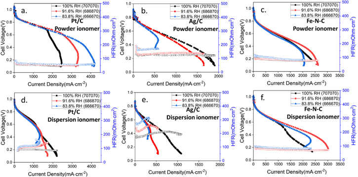
Figure 3. Fuel cell performance applied different catalyst under H2/O2 and 131 kPaa with different relative humidity (a)–(c) Catalyst with powder ionomer in the cathode electrode. (d)–(f) Catalyst with dispersion ionomer in the cathode electrode.
Download figure:
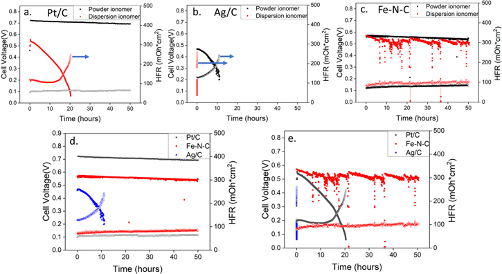
Standard image High-resolution imageWhile durability was not the primary focus of this study, short term durability studies were investigated and can provide additional value to data set presented. Fuel cell stability performance was evaluated at 600 mA cm−2 and cell voltage was recorded as function of testing time, shown in Fig. 4. Pt/C (Fig. 4a) and Ag/C (Fig. 4b) cathodes with powder ionomer exhibited much better stability compared to dispersion ionomer electrodes, while the durability of Fe–N–C (Fig. 4c) cathodes showed very similar performance for both ionomer types. Although the Fe–N–C cathode did show increased noise in the dispersion-based durability test, likely due to intermittent water management issues. The HFR values presented are also of interest where in multiple cases, significant increases in HFR occur in parallel with cell voltage loss. These results suggest that cell dry out and potentially membrane and/or ionomer degradation are important degradation reactions. Figures 4d and 4e allow for direct comparisons to be made between the different catalysts for the same ionomer depositions. Within the powder-based cathodes (Fig. 4d), both Pt/C and Fe–N–C show reasonable durability and low HFR, but Ag/C shows relatively low durability. Within the dispersion-based cathodes (Fig. 4e), only Fe–N–C shows reasonable durability and HFR, with Pt/C show relatively low durability and Ag/C showing essentially immediate catastrophic performance degradation. The mechanisms of these performance losses are not fully understood, but they highlight the impact different processing variables can have on cell degradation.
Figure 4. Fuel cell stability evaluation under H2/Air (CO2 free) condition at 600 mA cm−2 constant current density and at 70 °C cell temperature with 13 1kPa absolute pressure. (a) Pt/C as cathode catalyst. (b) Ag/C as cathode catalyst. (c) Fe–N–C as cathode catalyst. (d) Stability performance comparison with powder ionomer in cathode electrode. (e) Stability performance comparison with dispersion ionomer in cathode electrode.
Download figure:
Standard image High-resolution image
Conclusions
We successfully synthesized and applied powder and dispersion ionomer with different catalyst for fuel cell evaluation under various relative humidity. To our best of knowledge, this is the first time that two different types of ionomer deposition routes were investigated to probe fuel cell performance, and we expanded these studies to include three leading cathode catalyst choices. Carbon supported precious metal nanoparticle catalysts (Pt/C and Ag/C) showed greatly improved performance for powder ionomer than dispersion ionomers. Fe–N–C catalysts exhibited reasonable cell performance, essentially independent of electrode processing route. For the carbon supported precious metal nanoparticle catalyst, the result of electrochemical diagnostics with different MEA processing suggest that catalyst/ionomer interactions are critical in observed cell performance and stability. Fe–N–C catalysts were in general found to be less impacted by ionomer processing than traditional metal nanoparticle based electrocatalysts. The findings of these studies lend great insight into factors impacting electrode performance and may be critical in trying to further reduce precious metal loadings while also improving cell performance and durability.
Acknowledgments
The work was supported by the U.S. Department of Energy under Contract No. DEAC36-08GO28308 with Alliance for Sustainable Energy, LLC, the Manager and Operator of the National Renewable Energy Laboratory. Funding provided by the U.S. Department of Energy Office of Energy Efficiency and Renewable Energy Fuel Cell Technologies Office. The views expressed in the article do not necessarily represent the views of the DOE or the U.S. Government. The U.S. Government retains and the publisher, by accepting the article for publication, acknowledges that the U.S. Government retains a nonexclusive, paid-up, irrevocable, worldwide license to publish or reproduce the published form of this work, or allow others to do so, for U.S. Government purposes. The authors would like to acknowledge Dr. Guido Bender, Doug Wymore, and Chris Antunes for all the laboratory and equipment supports. Additionally, the authors would like to gratefully thank the research groups that provided us with polymer samples.