

Abstract
FeCoxNiyB nanoparticles with tuned cationic ratio integrated on Vertically Aligned Boron-doped Graphene Array (FeCoxNiyB@B-VG) electrocatalysts towards water splitting are successfully prepared by electroless plating. For a specific composition, FeCo66.7Ni33.3B@B-VG electrocatalyst exhibits the highest electrocatalytic activity towards hydrogen evolution reaction, with low overpotentials of 125 and 157 mV at η10 and small Tafel slopes of 52 and 47 mV dec−1 in 1.0 M KOH and 0.5 M H2SO4 solution, respectively. FeCo66.7Ni33.3B@B-VG electrocatalyst displays remarkable catalytic activity towards oxygen evolution reaction by showing low overpotentials of 200 and 569 mV at η10 and small Tafel slopes of 34 and 225 mV dec−1 in 1.0 M KOH and 0.5 M H2SO4 solution, respectively. The result of stability test exhibits that FeCo66.7Ni33.3B@B-VG electrocatalyst has long-term stability for at least 10 h towards water splitting in a wide pH range. And the faraday efficiency of FeCo66.7Ni33.3B@B-VG towards water splitting is around 90%. This study helps to explore the effect of variable cationic ratio in the fabrication of non-noble electrocatalyst to achieve enhanced electrocatalytic activity for water splitting in a wide pH range.
Export citation and abstract BibTeX RIS
The increasing energy demand caused by the depletion of the fossil fuels urges the need of sustainable resources. 1 Water splitting, the only pollutant-free industrial way to generate high purity hydrogen, has attracted great attention. The utilization of commercial noble electrocatalysts towards water splitting, such as Pt/C and IrO2/RuO2, are limited for their few reserves and poor stability. 2–4 Various non-noble high-efficient electrocatalysts have been synthesized as substitutes for noble-metal-based compounds electrocatalysts. Our previous work has proved that ternary iron group metal boride (FeCoNiB) possesses great potential as high-efficiency non-noble electrocatalyst towards water splitting for its excellent intrinsic activity that comes from the synergistic effect between Fe, Co and Ni, and its efficient electron transfer behavior between B atoms and transition metals. 5 Inspiringly, it is reported that the catalytic performance of iron group metal phosphides can be further improved by tuning the cationic ratio of Co and Ni. 6 It is a hint for tuning cationic ratio of FeCoNiB to get its catalytic performance strengthened, which is rarely reported. In general, the single-component FeCoNiB is prone to agglomerate, thus reducing the efficiency of the transportation of electrons. 7 Introducing carbon materials as substrate can efficiently solve the problem of agglomeration of loaded materials. 8 Vertical aligned graphene array is considered as excellent substrate for its great mass transfer capacity, remarkable conductivity and considerable mechanical strength, and its catalytic performance can be further improved by heteroatom doping. 9,10
Herein, FeCoxNiyB [x = Co/(Co + Ni)%, y = Ni/(Co + Ni)%] nanoparticles with tuned cationic ratio integrated on Vertically Aligned Boron-doped Graphene Array (FeCoxNiyB@B-VG) electrocatalysts have been fabricated by electroless plating. The catalytic performance of FeCoxNiyB@B-VG electrocatalysts towards overall water splitting is measured by electrochemical test to explore the influence of the cationic ratio of Co and Ni. This study provides a new avenue to tune cationic ratio of non-noble electrocatalyst for overall water splitting in a wide pH range to get it catalytically-enhanced, thus facilitating the development of overall water splitting.
Experimental
Reagents
NiSO4·6H2O, CoSO4·7H2O, FeSO4·7H2O, C6H5Na3O7·2H2O and C2H10BN (10% aqueous solution) were purchased from Shanghai Aladdin Biochemical Technology Co., Ltd Graphite powder (45 μm, 99.99% purity), H2SO4 (98%), HCl (37.5%), KOH, NaNO3, KMnO4, H2O2 (30%), ethanol, isopropanol and H3BO3 were purchased from Sinopharm Group Chemical Reagent Co., Ltd. Pt/C (20%) and IrO2 (99.0%) were purchased from Shanghai Macklin Biochemical Co., Ltd. Polytetrafluoroethylene (PTFE) pipes with inner diameter of 40 mm and thickness of 2 mm were purchased from Yangzhong Hongda Fluoroplastics Co., Ltd Copper plates with inner diameter of 44 mm and depth of 10 mm were purchased from Zhuji Yishun Building Materials Co., Ltd The PTFE pipe and the copper plate composed the mold of directional freezing. All the reagents were of analytical grade and used as received. Deionized water was used in all experiments.
Preparation of B-VG
GO was prepared by a modified Hummers method. 11 GO (120 mg) was dispersed in the mixture of 400 mg boric acid (the source of boron), 400 μl ethanol (antifreeze) and 10 ml deionized water by ultrasonicating for 1 h. Then the mixture was put in a mold assembled by polytetrafluoroethylene cylinder and copper plate. During the directional freezing process by liquid nitrogen, the ice crystals were influenced by gradients from bottom to the top, resulting in their growth along bottom to the top, and finally caused the formation of vertical aligned structure. 9 The mold was then put in a freeze-drying machine for 48 h. The freeze-dried samples were placed in a tubular furnace to get an annealing process, heated to 800 °C at a heating rate of 10 °C min−1 for 3 h in nitrogen atmosphere. Finally, the tubular furnace was cooled to room temperature, and the preparation of B-VG was completed.
Preparation of FeCoxNiyB@B-VG
The electroless plating baths were prepared according to Table I. The prepared B-VG was immerse into the bath and then heated to 110 °C and held for 5 min, following by adding 0.03 M C2H10BN. After the reaction last for 20 min. The products were washed with deionized water to remove the residual solution, and then put into a vacuum freeze-drying machine for 12 h. Finally, a series of composite electrocatalysts with different cationic ratio of Co and Ni were prepared. The theoretical composition and metal element ratio are shown in Table II.
Table I. Chemical deposition solution formulation of FeCoxNiyB@B-VG.
| Reagents | Bath 1 | Bath 2 | Bath 3 | Bath 4 |
|---|---|---|---|---|
| FeSO4·7H2O (mol L−1) | 0.05 | 0.05 | 0.05 | 0.05 |
| CoSO4·7H2O (mol L−1) | 0.025 | 0.05 | 0.10 | 0.125 |
| NiSO4·6H2O (mol L−1) | 0.125 | 0.10 | 0.05 | 0.025 |
| Na3C6H5O7 (mol L−1) | 0.075 | 0.075 | 0.075 | 0.075 |
| C2H10BN (mol L−1) | 0.03 | 0.03 | 0.03 | 0.03 |
Table II. Theoretical composition and ratio of metal elements in FeCoxNiyB@B-VG.
| Sample | Fe (wt%) | Co (wt%) | Ni (wt%) | x (wt%) | y (wt%) |
|---|---|---|---|---|---|
| FeCo16.7Ni83.3B@B-VG | 25 | 12.5 | 62.5 | 16.7 | 83.3 |
| FeCo33.3Ni66.7B@B-VG | 25 | 25 | 50 | 33.3 | 66.7 |
| FeCo66.7Ni33.3B@B-VG | 25 | 50 | 25 | 66.7 | 33.3 |
| FeCo83.3Ni16.7B@B-VG | 25 | 62.5 | 12.5 | 83.3 | 16.7 |
Characterizations
Field emission scanning electron microscopy (SEM, ZEISS Gemini 500) and field emission transmission electron microscope (HRTEM, Tecnai G2 F20) were utilized to examine the morphologies of the samples. Energy-dispersive X-ray spectrum (EDS) was used to analyze the proportion of the element in the samples. Elemental mapping was used to analyze the dispersion of different elements. X-ray diffraction (XRD) patterns using the Cu Kα radiation in Bragg-Brentano (θ − 2θ) configuration performed phase characterization of the FeCoxNiyB@B-VG. X-ray photoelectron spectra (XPS) was carried out on an X-ray photoelectron spectrometer system (ESCALAB Xi+).
Electrochemical measurements
The electrochemical performance of the catalyst was tested by CHI 660E electrochemical workstation (Shanghai Chenhua Instrument Co. Ltd.). In a typical three electrode system, the saturated calomel electrode (SCE) was used as the reference electrode and the graphite electrode was used as the counter electrode. The prepared electrocatalyst (effective area is 1 × 1 cm2) material was directly used as the working electrode. The electrochemical double-layer capacitance (Cdl) of the catalyst was measured by cyclic voltammetry (CV) in both 1.0 M KOH and 0.5 M H2SO4 electrolyte. The electrocatalytic properties of HER and OER were investigated by linear sweep voltammetry (LSV) and the scanning speed was 5 mV s−1 in 0.5 M H2SO4 and 1.0 M KOH electrolyte, respectively. The charge transfer resistance (Rct) and solution resistance (Rs) of the electrocatalyst was measured by electrochemical impedance (EIS) in 1.0 M KOH electrolyte. The stability of the electrocatalyst material was studied in 0.5 M H2SO4 and 1.0 M KOH electrolyte by chronopotentiometry (CP). The test time was 10 h. To evaluate the application potential of the FeCo66.7Ni33.3B@B-VG electrocatalyst, the faraday efficiency was tested. All the test potential was transformed into the reversible hydrogen electrode (RHE) potential by the equation: E(vs RHE) = E(vs SCE) + 0.241 + 0.05916 pH.
Results and Discussion
SEM, HRTEM and EDS analysis of FeCo66.7Ni33.3B@B-VG electrocatalyst
The vertically aligned structure of the side part and porous structure of the top part of FeCo66.7Ni33.3B@B-VG electrocatalyst resulting from the directional freezing are showed in the SEM image (Fig. 1a). The well-maintained structure demonstrates that B-VG has a remarkable mechanical strength, which allows no damage during the electroless plating process. In the gaps between the parallel graphene sheets, whose width is approximately 20–30 μm, some curly graphene bridges can be observed. The graphene bridges are beneficial for the conductivity of the electrocatalyst, and the bridges may come from the annealing process. 10 The even-distributed FeCo66.7Ni33.3B nanoparticles exhibited in Fig. 1b prove the excellent effect of B-VG on avoiding the nanoparticles from agglomeration. HRTEM (Fig. 1c) exhibits that the average size of the FeCo66.7Ni33.3B nanoparticles is around 100 nm. Figure 1d demonstrates the high crystallinity of the FeCo66.7Ni33.3B nanoparticles with the lattice fringes of (211), (110) and (110) attribute to BFe2, Fe7Ni3 and Co3Fe7 phases, respectively. EDS spectrum and column of detailed data (Fig. 1e) display that the atomic percentage of Co and Ni is 15.81% and 7.79%, and the relative contents of Co and Ni are x = Co/(Co + Ni)% = 67.0% and y = Ni/(Co + Ni)% = 33.0%, which proves tuning cationic ratio of FeCo66.7Ni33.3B nanoparticles by electroless plating is successful. Elemental mapping pictures (Figs. 1f–1k) exhibit the dispersion situation of element C, B, O, Fe, Co and Ni, respectively. The dispersion situation of C and B (Figs. 1f and 1g) demonstrates that the B element may successfully doped into the graphene sheets, and the B element concentrates more in the center of the Fig. 1g means that B element exists in the nanoparticle. Figure 1h displays the distribution of O element, the even-distributed O element may come from the oxygen-containing groups on the surface of the graphene. And in the center of Fig. 1h, the more concentrated O element may come from the oxidized surface of the FeCo66.7Ni33.3B nanoparticle, which is attributed to the inevitable contact with the air. Figures 1i–1k show the well-distributed element of Fe, Co and Ni in single nanoparticle, thus proving the successful synthesis of FeCo66.7Ni33.3B.
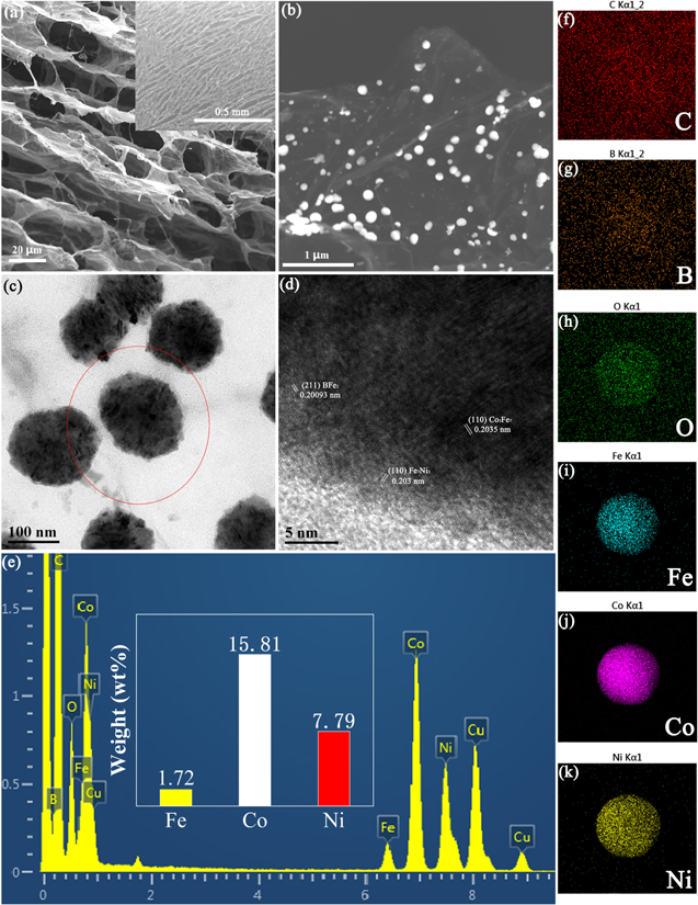
Figure 1. SEM images of FeCo33.3Ni66.7B@B-VG (a), (b), HRTEM images of FeCo33.3Ni66.7B@B-VG (c), (d), EDS spectrum of FeCo33.3Ni66.7B@B-VG (e), Elemental mapping of FeCo33.3Ni66.7B@B-VG (f)–(k).
Download figure:
Standard image High-resolution imageElectrochemical property of the prepared electrocatalysts
Catalytic property of the prepared electrocatalysts for HER
According to Fig. 2a, FeCo66.7Ni33.3B@B-VG electrocatalyst achieves a current density of 10 mA cm−2 at a low overpotential of 157 mV in 0.5 M H2SO4 electrolyte, which is comparable to that of Pt/C@B-VG (146 mV), and much better than FeCo33.3Ni66.7B@B-VG, FeCo83.3Ni16.7B@B-VG and FeCo16.7Ni83.3B@B-VG. Furthermore, the Tafel slope of FeCo66.7Ni33.3B@B-VG is given as merely as 47 mV dec−1 (Fig. 2b), which is comparable to that of Pt/C@B-VG (57 mV dec−1), and significantly smaller than the others. As shown in Fig. 2c, the FeCo66.7Ni33.3B@B-VG electrocatalyst delivers the best HER catalytic activity in 1.0 M KOH solution by displaying a low overpotential of 125 mV at a current density of 10 mA cm−2, indicating its outstanding HER electrocatalytic performance, which is even better than Pt/C@B-VG (150 mV). The Tafel slope of FeCo66.7Ni33.3B@B-VG is 52 mV dec−1 in 1.0 M KOH solution (Fig. 2d), also lower than that of Pt/C@B-VG (55 mV dec−1) and other prepared electrocatalysts. The different electrocatalytic performance of FeCoxNiyB means that the appropriate increase of Co content in FeCoxNiyB@B-VG can effectively reduce the overpotential of water splitting and improve the electrocatalytic activity of the materials. Excessive content of Co will decrease the electrocatalytic performance instead. Because different metal has its own function for water splitting. For example, Co element is beneficial to decrease the overpotential, Ni element is helping to boost the current. 12 Excessive content of Co will cause the reduction of the relative content of Ni and result a weakened synergistic effect between Co and Ni, thus reducing the electrocatalytic activity of the materials.

Figure 2. Linear sweep voltammetry (LSV) curves of FeCoxNiyB@B-VG and Pt/C@B-VG in 0.5 M H2SO4 (a), 1.0 M KOH (c) towards HER. Tafel plots of FeCoxNiyB@B-VG and Pt/C@B-VG in 0.5 M H2SO4 (b) and 1.0 M KOH (d) towards HER.
Download figure:
Standard image High-resolution imageCatalytic property of the prepared electrocatalysts for OER
According to Fig. 3, FeCo66.7Ni33.3B@B-VG possesses the best OER activity among as-prepared samples, with overpotential of 569 mV and 200 mV at current density of 10 mA cm−2 and Tafel slope of 225 mV dec−1 and 34 mV dec−1 in 0.5 M H2SO4 and 1.0 M KOH, respectively. FeCo66.7Ni33.3B@B-VG even shows a better catalytic performance than IrO2@B-VG (overpotential of 318 mV and Tafel slope of 90 mV dec−1) in 1.0 M KOH solution. In Fig. 3c, the slightly raised peak at 1.38 V may be attributed to the oxidation of metal. The higher performance of OER is usually related to the conversion from metal to oxide/hydroxide, which serves as active sites during OER, on the surface of the borides, and the oxide/hydroxide layer can also improve the stability of OER in alkaline solution. 13–15 All the as-prepared samples demonstrate a worse catalytic performance in 0.5 M H2SO4 solution compared with IrO2 (overpotential of 256 mV and Tafel slope of 245 mV dec−1), because the corrosion charge of transition metal compounds at anode is fast in acidic solution. 14 From these phenomena, it can be found that with the relative content of Co increasing from 16.7% to 66.7%, HER and OER electrocatalytic activities of the catalyst also increase correspondingly. However, when the relative content of Co is further increased to 83.3% and the content of Ni is reduced to 16.7%, the electrocatalytic activity of the catalyst decreases greatly. In a word, when the relative contents of Co and Ni are 66.7% and 33.3% respectively, a best catalytic performance of FeCoxNiyB is achieved.
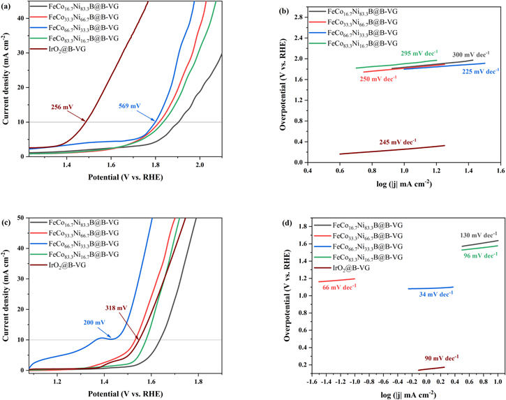
Figure 3. Linear sweep voltammetry (LSV) curves of FeCoxNiyB@B-VG and IrO2@B-VG in 0.5 M H2SO4 (a), 1.0 M KOH (c) towards OER. Tafel plots of FeCoxNiyB@B-VG and IrO2@B-VG in 0.5 M H2SO4 (b) and 1.0 M KOH (d) towards OER.
Download figure:
Standard image High-resolution imageXRD and XPS analysis of the FeCo66.7Ni33.3B@B-VG electrocatalyst
The XRD patterns of FeCo66.7Ni33.3B@B-VG and B-VG as comparison are exhibited in Fig. 4a. The peak of B-VG located at 2θ = 24° disappears in the XRD pattern of FeCo66.7Ni33.3B@B-VG for the intensities of peaks ascribe to FeCo66.7Ni33.3B are too strong. The peak centered at 2θ = 44.84° in the XRD pattern of FeCo66.7Ni33.3B@B-VG can be ascribed to the (211) plane of BFe2 (JCPDS card no.65-2693) and (110) planes of Co3Fe7 and Fe7Ni3 (JCPDS card no.48-1816, no.65-7251). The peak centered at 2θ = 65.1° can be ascribed to the (110) planes of Co3Fe7 and Fe7Ni3 (JCPDS card no. 48-1816, no. 65-7251). The planes of FeCo66.7Ni33.3B@B-VG can match well with the results achieved by the HRTEM analysis, and the shape of the peaks means that FeCo66.7Ni33.3B@B-VG electrocatalyst is well crystalline. Figure 4b shows the XPS spectra about FeCo66.7Ni33.3B@B-VG and there are six characteristic peaks of B 1s, C 1s, O 1s, Fe 2p, Co 2p and Ni 2p, illustrating the FeCo66.7Ni33.3B@B-VG catalyst material is composed of B, C, O, Fe, Co and Ni. The Fe 2p spectrum of FeCo66.7Ni33.3B@B-VG (Fig. 4c) observes three peaks, the fitted peak at 715.35 eV can be attributed to Fe2+ 2p3/2. The peaks at 709.7 and 721.9 eV are due to the zero-valence state of Fe 2p3/2 and Fe 2p1/2, respectively. 16,17 The Co 2p spectrum of FeCo66.7Ni33.3B@B-VG (Fig. 4d) exhibits four peaks. The peaks located around 778.5 and 794.15 eV are assigned to metal Co 2p3/2 and Co 2p1/2. The peaks around 783.15 eV and 799.95 eV are also detected, which are assigned to the Co2+ 2p3/2 and Co2+ 2p1/2. 16,17 In the Ni 2p spectrum (Fig. 4e), the peaks at 825.90 eV and 870.60 eV are assigned to Ni 2p3/2 and Ni 2p3/2, respectively. And the peak at 849.5 eV is assigned to satellite peak. The other peaks at 858.4 and 876.85 eV are attributed to Ni2+ 2p3/2 and Ni2+ 2p1/2. 16,17 From the B1s spectrum in Fig. 4f, two peaks at 188.48 and 195.73 eV for FeCo66.7Ni33.3B@B-VG are attributed to the alloying structure of B, which confirms the existence of FeCoNi-B, B3C and the oxidation species of B, including CB2O, CBO2 and B2O3. 18–20 B2O3 can be attributed to the oxidation of the electrocatalyst. 21 In the C 1s spectrum (Fig. 4g), the peaks at 208.24, 281.2, 281.85, 282.65 and 285.35 eV are related to the C-B, sp2C, sp3C, C−O and O−C=O, respectively. 22–24 C-B indicates that B has successfully substituted for C atom and doped into graphene lattice, which is correspond to the B3C peak observed in Fig. 4f and the hypothesis from the EDS mapping (Fig. 1g). 25–28 C−O and O−C=O structures with higher binding energy originate from incomplete reduction of graphene. For the high-resolution O 1 s spectrum in Fig. 4h, three types of O configurations are ascribed to adsorbed oxygen (528.34 eV), OH (526.56 eV), and OOH (529.19 eV). 29–31 The specific content calculated by fitting the peak area of each element is shown in Fig. 4i, it was found that the atomic ratio of Co and Ni in the sample is 3.98% and 1.89%, respectively. The relative content of Co is x = Co/(Co + Ni)% = 67.8%, and the relative content of Ni is y = Ni/(Co + Ni)% = 32.2%, which is very close to the data got from EDS analysis, indicating that the adjustment of the relative contents of Co and Ni in this sample is very successful.
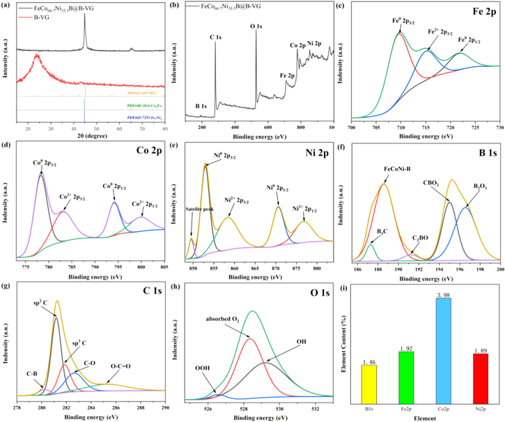
Figure 4. The XRD patterns (a) and XPS survey spectra of FeCo66.7Ni33.3B@B-VG (b). High-resolution XPS Fe 2p (c), Co 2p (d), Ni 2p (e), B 1 s (f), C 1 s (g) and O 1 s (h) spectra of FeCo66.7Ni33.3B@B-VG. Element content of B1s, Fe2p, Co2p and Ni2p calculated from XPS peak area (i).
Download figure:
Standard image High-resolution imageElectrochemical surface area (ECSA) test, EIS analysis and electrochemical stability test
As shown in Fig. 5a, the FeCo66.7Ni33.3B@B-VG exhibits a Cdl value of 40.4 mF cm−2 in acidic solution, which is larger than those of the FeCo33.3Ni66.7B@B-VG (30.9 mF cm−2), FeCo83.3Ni16.7B@B-VG (24.6 mF cm−2) and FeCo16.7Ni83.3B@B-VG (23.5 mF cm−2) electrocatalysts, indicating that more active sites and a larger ECSA exist in FeCo66.7Ni33.3B@B-VG. Similarly, the Cdl values of the prepared electrocatalysts in alkaline solution are also exhibited in Fig. 5b, FeCo66.7Ni33.3B@B-VG exhibits a Cdl value of 43.8 mF cm−2, which is much bigger than those of FeCo33.3Ni66.7B@B-VG (32.2 mF cm−2), FeCo83.3Ni16.7B@B-VG (31.4 mF cm−2) and FeCo16.7Ni83.3B@B-VG (26.7 mF cm−2). As presented in Fig. 5c, the FeCo66.7Ni33.3B@B-VG shows lower Rct and Rs than others, suggesting that when the relative contents of Co and Ni are 66.7% and 33.3%, the FeCoxNiyB exhibits best intrinsic catalytic activity. 32 As exhibited in Fig. 5d, the catalytic activities towards HER in both 0.5 M H2SO4 and 1.0 M KOH solutions and catalytic activity towards OER in 1.0 M KOH solution can be maintained for at least 10 h. After 10 h, the potential of FeCo66.7Ni33.3B@B-VG decays very little, indicating that FeCo66.7Ni33.3B@B-VG electrocatalyst maintains good long-term stability towards HER in a wide pH range, even in acid condition. And FeCo66.7Ni33.3B@B-VG electrocatalyst exhibits remarkable long-term stability towards OER in alkaline solution as well. It can be observed from the picture that in the double-electrode system, when the FeCo66.7Ni33.3B@B-VG electrocatalyst is directly used as the electrodes in the water splitting reaction, dense H2 and O2 bubbles are formed at the cathode and anode respectively. The material does not deform or disintegrate, which means a good mechanical strength of FeCo66.7Ni33.3B@B-VG. In short, the long-term stability comes from the great mass transfer capacity and mechanical strength of the FeCo66.7Ni33.3B@B-VG electrocatalyst and the good intrinsic stability of FeCo66.7Ni33.3B nanoparticles. Furthermore, the oxide/hydroxide layer produced during OER on the surface of the FeCo66.7Ni33.3B nanoparticles helps to improve the stability towards OER in alkaline solution. 14

Figure 5. Cdl of FeCoxNiyB@B-VG in 0.5 M H2SO4 (a) and 1.0 M KOH (b), EIS of FeCoxNiyB@B-VG tested in 1.0 M KOH (c). The stability of FeCo33.3Ni66.7B@B-VG towards HER in 1.0 M KOH and 0.5 M H2SO4 solutions and OER in 1.0 M KOH solution by chronopotentiometry (CP) at 10 mA cm−2 and an optical photo of H2 and O2 bubbles generated on the FeCo66.7Ni33.3B@B-VG electrodes (d).
Download figure:
Standard image High-resolution imageThe faraday efficiency of the prepared FeCo66.7Ni33.3B@B-VG electrocatalyst
Figure 6a shows the measured volume of H2 and O2 generated by FeCo66.7Ni33.3B@B-VG when the current density reaches 10 mA cm−2 during water splitting. The amount of H2 collected is about twice as much as the amount of O2. Figure 6b exhibits that the corresponding Faraday efficiency of FeCo66.7Ni33.3B@B-VG is around 90% according to the measured gas volume, indicating that the FeCo66.7Ni33.3B@B-VG electrocatalyst has a high efficiency and great potential for application.
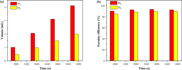
Figure 6. The measured volume of H2 and O2 generated by FeCo66.7Ni33.3B@B-VG when the current density reaches 10 mA cm−2 during water splitting (a). Corresponding Faraday efficiency of FeCo66.7Ni33.3B@B-VG (b).
Download figure:
Standard image High-resolution imageComparison between FeCo66.7Ni33.3B@B-VG electrocatalyst and other reported electrocatalysts
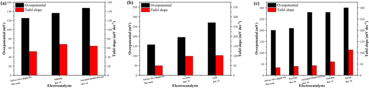
The catalytic properties of different transition metal composite electrocatalysts for water splitting in different electrolytes are exhibited in Fig. 7. 33–38 It can be concluded that FeCo66.7Ni33.3B@B-VG has higher electrocatalytic activity than other transition metal composite electrocatalysts.
Figure 7. Comparison of catalytic activities for HER in 1.0 M KOH (a) and 0.5 M H2SO4, for OER in 1.0 M KOH (c) between FeCo66.7Ni33.3B@B-VG and reported non-noble metal catalysts.
Download figure:
Standard image High-resolution image
Conclusions
In summary, we have successfully synthesized a series of FeCoxNiyB nanoparticles with tuned cationic ratio fused on B-VG by electroless plating as efficient self-supported bifunctional electrocatalyst towards overall water splitting. For specific cationic ratio, FeCo66.7Ni33.3B@B-VG exhibits the optimal activity towards water splitting in a wide pH range due to the great mass transfer capacity and conductivity from the unique vertical aligned structure, the fabulous distribution and number of FeCo66.7Ni33.3B nanoparticles and most importantly the great intrinsic activity of FeCo66.7Ni33.3B nanoparticles from appropriate cationic ratio of Co and Ni. This study explores the effect of tuning cationic ratio of FeCoxNiyB to strengthen its catalytic performance towards overall water splitting in a wide pH range, which is beneficial to the development of non-noble electrocatalyst towards water splitting, thus pushing the industrialization of water splitting.
Acknowledgments
This work was financially supported by the Key Technology Research and Development Program of Shaanxi province (CN) (No. 2021KW-24) and National Natural Science Foundation of China (No. 21902127).