
Abstract
Lithium-ion batteries (LIBs) are ubiquitous power sources and demand for higher energy and higher performance LIBs than state-of-the-art ones continues to increase for longer range use of electric mobility and energy-storage systems. Performance of conventional LIBs is often limited or failed in tough working environments, particularly, subzero-temperatures because of reduced ionic conductivity of electrolyte and diffusion kinetics of both anode and cathode, causing lithium metal plating and dendrite growth and finally safety issue and death of LIBs. Herein, for the first time we report a lithium metal plating-free and unprecedented high-performance graphite∥LiNi0.8Co0.1Mn0.1O2 (NCM811) full-cell under subzero-temperature of −10 °C and high-voltage of 4.45 V through the construction of robust solid electrolyte interphase (SEI) layers at both anode and cathode and their structural stabilization in 1 M LiPF6 and nonflammable electrolyte. Subzero-temperature operation of commercial electrolyte-based full-cell however results in a drastic performance failure in early cycles and shows distinguishing marks such as lithium metal plating at graphite anode and irreversible phase transformation of NCM811 to disordered H3 phase with a large volume contraction. The strong correlation between anode-electrolyte and cathode-electrolyte interfacial stabilization, bulk structural stabilization of both anode and cathode, and highly reversible cycling performance under subzero-temperature is clearly demonstrated.
Export citation and abstract BibTeX RIS

This is an open access article distributed under the terms of the Creative Commons Attribution Non-Commercial No Derivatives 4.0 License (CC BY-NC-ND, http://creativecommons.org/licenses/by-nc-nd/4.0/), which permits non-commercial reuse, distribution, and reproduction in any medium, provided the original work is not changed in any way and is properly cited. For permission for commercial reuse, please email: permissions@ioppublishing.org.
State-of-the-art lithium (Li)-ion batteries (LIBs) are dominant and ubiquitous power sources for various mobile electronic devices, robots, drones, and electric mobility like electric vehicles (EV), e-bikes and e-scooters, and grid-based stationary energy storage systems (ESS). The corresponding markets for electrified community are predicted to rapidly grow to more than tenfold within the next tens of years. The LIB-powered devices, in particular, electric mobility is often exposed to changeable temperatures at outside. Under subzero-temperatures and in extreme environments such as cold region, cold season and aerospace, LIBs show a drastic reduction in energy and performance. 1,2 Commercial LIBs work based on the battery chemistry of lithium metal oxide cathode, graphite anode and flammable ethylene carbonate (EC)-based commercial organic liquid electrolyte. As high melting point (mp; 36.4 °C) of EC imposes the limited operation temperature range of LIBs to above room temperature, EV/ESS's battery operation under subzero-temperatures often requires a thermal management system equipped on the battery package to maintain the operation temperature near room temperature. 3,4 Much less concern has been paid to the subzero-temperature phenomena and failure modes of LIBs than those of elevated temperatures. The subzero-temperature performance of LIBs is hampered by multiple factors including the reduced Li+-ion conductivity of commercial electrolyte, reduced Li+-ion diffusion kinetics on cathode and anode and the solid electrolyte interphase (SEI) layer, and a phase change of EC from liquid to solid. 5 First of all, the search and utilization of lower mp solvent must be a way out of the subzero-temperature dilemma of EC-based commercial electrolyte.
More importantly, a critical issue to address is the occurrence of Li metal plating and dendritic growth at graphite anode under subzero-temperatures. 6 Solvated Li+ ions by EC stay longer at the anode-electrolyte interface during charging (Li+-intercalation) under subzero-temperatures due to a sluggish diffusion kinetics by stepwise Li+-intercalation into graphite interlayers and staging. Thus, higher chance of Li metal deposition by electrochemical reduction of Li+ ions causes Li metal plating and coexistence of phases at lower staging, leading to an irreversible capacity loss and safety hazard. 4 If harmful Li-dendrite growth occurred at graphite anode, it can pierce separator and touch the opposite side, cathode. The results are prone to short-circuiting with the generation of a heat and thermal runaway, finally leading to sudden death of a LIB and/or a LIB to catch fire. The same event often occurs under the bursts of high current, i.e., fast charging rates. 5 Such unsafe modes are intensified at a high state of charge (i.e. high charge cut-off voltages). Eliminating or reducing the chance of Li metal plating is vitally essential for battery safety and moreover large-scale and wide range temperature operation of LIBs. An ultimate solution to the Li metal plating issue must be to drive the electrolyte to form a surface-passivating SEI layer at graphite anode earlier than the occurrence of Li metal plating. Many of subzero-temperature electrolyte researches had been specifically focused on LiCoO2 chemistry-based commercial LIBs for aerospace applications. 7 High-energy LIBs on high-capacity nickel-rich layered oxide cathode under high charge cut-off voltages beyond conventional 4.2 V under subzero-temperatures have not been explored.
Herein, we present an unprecedented subzero-temperature (−10 °C) performance and Li metal plating-free 4.45 V graphite∥LiNi0.8Co0.1Mn0.1O2 (NCM811) Li-ion full-cells with nonflammable organic liquid electrolyte taking the benefit of low mp (−48.8 °C) of PC, 8 beyond the cells with EC-based flammable commercial electrolyte that causes Li metal plating in the same condition. By conventional perception, PC has been known as a very bad choice for graphite anode due to the occurrence of PC co-intercalation together with Li+ ion into graphite interlayers followed by exfoliation of graphene sheets and performance failure. 9–11 Nonetheless, this is the first report and a breakthrough of unprecedented high-performance of high-voltage and high-energy, and subzero-temperature NCM811 chemistry-based 4.45 V Li-ion full-cells in nonflammable electrolyte of 1 M LiPF6 and PC:FEMC:DFDEC solvents. Systematic mechanistic studies clarify the reasons of how nonflammable electrolyte enables to prevent Li metal plating, and what interfacial phenomena are present under −10 °C, how interface and structure of graphite anode and NCM811 cathode are evolved with cycling under 4.45 V high charge cut-off voltage and simultaneously under −10 °C, utilizing surface-sensitive attenuated total reflectance (ATR) FTIR spectroscopy and X-ray photoelectron spectroscopy (XPS) combined with bulk structural analyses of X-ray diffraction, Raman spectroscopy and scanning electron microscopy. A basic understanding of anode-electrolyte and cathode-electrolyte interfacial phenomena and the interplay between anode and cathode in nonflammable electrolyte under subzero-temperature, and the strong correlation to enhanced performance are demonstrated. This would pave the way of a wider use of high-safety and high-energy LIBs for powering EV and ESS at outdoor, cold region and in cold season.
Experimental
Electrochemistry
Commercial electrolyte of 1 M LiPF6/ethylene carbonate (EC): ethyl methyl carbonate (EMC) (3:7 volume ratio) was used as purchased (Enchem, Co., Ltd.). Lithium hexafluorophosphate (LiPF6; Sigma Aldrich), propylene carbonate (PC), methyl (2,2,2-trifluoroethyl)carbonate (FEMC; Lichem. Ltd.), di-(2,2,2-trifluoroethyl) carbonate (DFDEC; Lichem. Co., Ltd.) (3:2:5 volume ratio) and fluoroethylene carbonate (FEC; Lichem. Co., Ltd.) were used as received. Nonflammable electrolyte of 1 M LiPF6/PC:FEMC:DFDEC (3:2:5 volume ratio) was prepared by dissolving 1 M LiPF6 salt in the mixed solvents of PC:FEMC:DFDEC in the Ar-filled glove box (MOTek) with water and oxygen contents less than 0.5 ppm. 8 The ionic conductivity of commercial electrolyte and nonflammable electrolyte were measured with three-electrodes blocking-cells consisting of stainless steel working and counter electrodes, and lithium foil as a reference electrode under various temperatures of −20 °C, −10 °C, 0 °C, +15 °C, +25 °C and +45 °C after keeping the cell at each temperature for an hour to equilibrate with the desired temperature, employing electrochemical impedance spectroscopy. The ionic conductivity of electrolytes was calculated from the equation, σ = t/Rb A, where A is the electrolyte-electrode contact area and t is the thickness of separator that is fully wet with electrolyte and thus so called electrolyte film, respectively, and Rb is bulk resistance, obtained from the intersection of the real impedance axis. 12,13 The room temperature ionic conductivity of commercial electrolyte and nonflammable electrolyte measured under argon atmosphere utilizing a conductivity meter (Mettler Toledo S230) were 9.19 and 3.49 mS cm−1, respectively. 8
Graphite anode coated on a copper, was composed of 85 wt% graphite active material (supplied from an industry), 5 wt% carbon black (Super P; Timcal) and 10 wt% styrene-butadiene rubber (SBR; Sigma Aldrich), sodium carboxyl methyl cellulose (CMC; Sigma Aldrich), aqueous binder. Active mass loading of anode was ≈2.3 mg cm−2. NCM811 cathode was prepared by coating the slurry, which was composed of 80 wt% NCM811 active material (supplied from an industry), 10 wt% carbon black (Super P, Timcal) and 10 wt% polyvinylidene fluoride binder (PVdF; Aldrich) in N-methyl-2-pyrrolidone (NMP; Aldrich) solvent, onto an aluminum foil. Active mass loading of cathode was ≈4.0 mg cm−1. The N/P ratio was 1.1. Both coated graphite anode and NCM811 cathode were dried at 110 °C under vacuum overnight. Lithium 2032 coin full-cells, consisting of graphite anode, NCM811 cathode, separator (Celgard C210) and 200 μL of the commercial electrolyte of 1 M LiPF6/EC:EMC or nonflammable electrolyte of 1 M LiPF6/PC:FEMC:DFDEC with 3 wt% FEC additive, were assembled in an argon-filled glove box (MOTek) that contains oxygen and water less than 1 ppm. First, rate capability of graphite∥NCM81 full-cells was tested under elevated (+45 °C), room (+25 °C) and subzero (−10 °C) temperatures by charging to 4.45 V at 0.1 C and by discharging to 2.7 V at variable rates ranged from 0.1, 0.2, 0.5, 1 C, 2 C, 5 C to 10 C, following first two formation cycles at 25 °C between 2.7 and 4.45 V (corresponding to 4.5 V vs Li/Li+) at the rate of 0.1 C in a constant temperature chamber using a multichannel battery cycler (WBCS3000, Won-A Tech). Cycling of full-cells under −10 °C and 0 °C were conducted between 2.7 and 4.45 V at 0.2 C, after two formation cycles at 0.1 C at 25 °C. Simultaneously, AC impedance spectral measurement was conducted at the equilibrated open circuit voltage ≈ 2.7 V under −10 °C after the 1st and 100th cycle of main cycles at 0.2 C under −10 °C, using an impedance spectroscopic analyzer (VSP SP-150, Bio-Logic) in the frequency range from 100 kHz to 10 mHz with an amplitude of 10 mV.
Material characterization
After cycling under −10 °C, full-cells were disassembled at room temperature in the glove box under argon atmosphere for various ex-situ analyses. Cycled anodes and cathodes were washed with dimethyl carbonate (DMC; Soulbrain) to remove electrolyte residue and dried in the glove box at room temperature. Morphology changes of graphite anodes and NCM811 cathodes and the crack formation behavior of NCM811 cathodes with cycling were monitored using field emission scanning electron microscopes (FE SEM—SU8230 Hitachi) at 15 kV. Local structural change of graphite anode with cycling was examined with a Raman microscope (Nanofinder 30, Tokyo Instrument Co. in Korea Basic Science Institute), using 532 nm line of a He-Ne laser at 1.5 mW. The size of the laser beam at the sample was less than 1 μm in diameter. The spectral measurement was conducted using a closed cell to avoid atmospheric contamination, where the cycled graphite anodes were placed below a glass window in the glove box. The crystal structural change of NCM811 cathode with cycling was examined with X-ray diffraction (XRD) by a powder X-ray diffractometer (Rigaku D/MAX-2200) from 10° to 80° 2θ at the scan rate of 1° min−1 at 40 kV and 40 mA, using Ni-filtered Cu-Kα radiation. The samples were mounted in a tightly sealed sample holder to avoid atmospheric contamination.
For the studies of the SEI formation under subzero-temperature, the pristine and cycled anodes and cathodes with commercial electrolyte and the nonflammable electrolyte without and with FEC additive, respectively, were collected with attenuated total reflection (ATR) FTIR spectroscopy, using Nicolet 6700 spectrometer equipped with a mercury-cadmium-telluride (MCT) detector and a Ge optic. Those were directly mounted on the tightly closed ATR unit in the glove box to avoid atmospheric contamination during transportation to the dry nitrogen-purged sample compartment of IR instrument as well as during IR measurement. The spectra were acquired with 512 scans and spectral resolution of 4 cm−1. Elemental basis surface chemical state and composition of cycled anodes and cathodes were analyzed using X-ray photoelectron spectroscopy (XPS) instrument (Thermo, MultiLab 2000) with Al Kα X-ray source at 15 kV. High resolution spectra were obtained at a power of 150 W under a commercial pressure of 5 × 10⁻¹⁰ mbar with the pass energy of 100 eV. The cycled graphite anodes and cathodes were transferred from glove box to the XPS chamber using a vacuum sealed container without exposure to the air. The spot size was about 500 μm and the pass energy was 30 eV. Binding energy was corrected based on the C 1s level at 284.5 eV. To avoid the interfering effect of F Auger peak in Ni and Co 2p spectra, NCM811 cathodes were measured using Mg Kα X-ray source at 15 kV with the irradiated large AXPS spot size of 4 mm and the pass energy of 30 eV. Curve-fitting was conducted on the Ni 2p3/2 and Mn 2p3/2 peaks with Gaussian (20%) and Lorentzian (80%) functions using XPSPEAK 4.1 program till the goodness of fit is minimized, after having Shirley-type background correction. The full-width-half-maximum of each component in one spectrum was set to be ±0.1 as the same. SEM-energy dispersive spectrometer (EDS) elemental mapping was conducted on cycled graphite anodes.
Results and Discussion
Ionic conductivity of electrolytes and temperature-dependent rate capability of full-cells
To understand temperature-dependent ionic conduction behavior, we measured ionic conductivity of electrolytes (Fig. 1a) from −20 °C (−4 °F) to +45 °C (113 °F) employing impedance spectroscopy. Overall, with increasing the temperature, ionic conductivity gradually increases, and vice versa. For commercial electrolyte of 1 M LiPF6/EC:EMC (Fig. 1a), the ionic conductivity slightly increases from 0.27 to 0.62 mS cm−1 as increasing the temperature. 14 It is linked to the decrease in viscosity. 15 Nonflammable electrolyte of 1 M LiPF6/PC:FEMC:DFDEC shows lower ionic conductivities in the entire temperature range from 0.06 to 0.34 mS cm−1 with increasing the temperature than those of commercial electrolyte, probably due to relatively higher viscosity of PC (2.52 cP) than EC (1.93 cP), and FEMC (1.36 cP) and DFDEC (2.69 cP) than EMC (0.65 cP), respectively. 14,16–18 The activation energy (Ea ) (Fig. 1b) of commercial electrolyte is 70.03 KJ mol−1, which is obtained from the Arrhenius plots of logarithmic conductivity vs 1000/T plot. This is lower than 97.07 KJ mol−1 of nonflammable electrolyte, implying a relatively slower ion conduction behavior of nonflammable electrolyte.
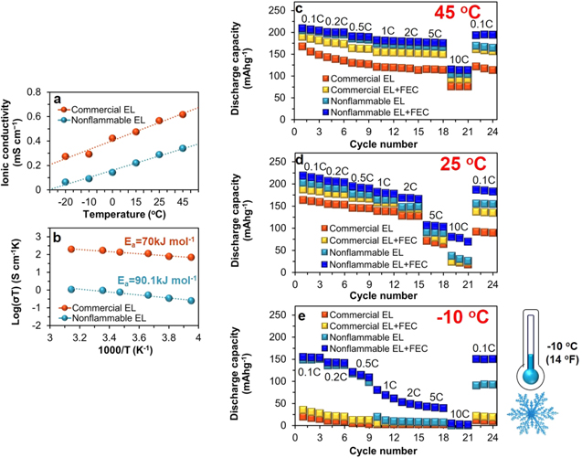
Figure 1. (a) Temperature-dependent ionic conductivity of commercial electrolyte (EL) of 1 M LiPF6/EC:EMC and nonflammable EL of 1 M LiPF6/PC:FEMC:DFDEC in the temperature range from −20 °C to + 45 °C measured with impedance spectroscopy and (b) corresponding Arrhenius plots. Rate capability of graphite∥NCM811 full-cell with commercial EL without and with 3 wt% FEC additive and nonflammable EL without and with 3 wt% FEC additive between 2.7 and 4.45 V under (c) + 45 °C (d) +25 °C (e) −10 oC.
Download figure:
Standard image High-resolution imageFigures 1c–1e display the temperature-dependent rate capability of graphite∥NCM811 full-cells with commercial electrolyte without and with 3 wt% FEC additive and nonflammable electrolyte without and with 3 wt% FEC additive between 2.7 and 4.45 V under various temperatures of +45 °C (Fig. 1c), +25 °C (Fig. 1d) and −10 °C (Fig. 1e). Variable discharge rates of 0.1 C, 0.2 C, 0.5 C, 1 C, 2 C, 5 C, 10 C were applied to the cells in a sequential manner for three cycles at each rate. As increasing the rate, the capacity of all full-cells decreases gradually in common at all temperatures. Nonflammable electrolyte systems outperform commercial electrolyte systems at all temperatures and at all rates. While commercial electrolyte only exhibits the lowest capacities and the worst capacity retention, nonflammable electrolyte with 3 wt% FEC additive provides the highest capacity and the highest capacity retention. Upon the return of rate to 0.1 C after cycling at 10 C, the cell with nonflammable electrolyte with FEC additive shows the capacity retention of 93% at +45 °C and 85% at +25 °C. In particular, under −10 °C (Fig. 1e), the deviation of rate capability very largely increases depending on electrolyte. With nonflammable electrolyte with FEC additive under −10 °C (Fig. 1e), average capacity delivered at 0.1 C is 155 mAh g−1, from which 92% is retained at 0.2 C, 78% at 0.5 C, 52% at 1 C, 34% at 2 C, 27% at 5 C and 3% at 10 C. From 1 C to 10 C, capacity reduction is pronounced. When the rate returns from 10 C to 0.1 C, 97% (150 mAh g−1) of the capacity that is delivered at the initial 0.1 C is retained. In nonflammable electrolyte without FEC additive, from 1 C to 10 C, similar capacity fade behavior to commercial electrolyte systems occurs. Capacity retention upon the rate return to 0.1 C is notably lower, 60%, than the one with FEC additive but much higher than those of commercial electrolyte systems. These data experimentally prove and point out the critical roles and the innovative effectiveness of firstly nonflammable electrolyte and secondly FEC additive in improving the rate capability under −10 °C, despite lower ionic conductivity (Fig. 1a) of nonflammable electrolyte than commercial electrolyte systems. Despite lower ionic conductivity and higher Ea of nonflammable electrolyte, rate capability and battery performance under high voltage and subzero-temperature rely on multiple factors of electrolyte such as electrochemical stability and interfacial compatibility and stability with anode and cathode, etc. Higher anodic stability of our nonflammable electrolyte by the presence of fluorinated linear carbonates guarantees improved high voltage stability beyond conventional 4.2 V, in contrast to unstable commercial electrolyte, making it promoted rate capability under −10 °C. 8,16,17,19
Subzero-temperature performance of graphite∥NCM811 lithium-ion full-cell
Figure 2 exhibits electrochemical cycling performance under −10 °C of graphite∥NCM811 full-cells between 2.7 and 4.45 V at 0.2 C in commercial electrolyte of 1 M LiPF6/EC:EMC without and with 3 wt% FEC additive and nonflammable electrolyte of 1 M LiPF6/PC:FEMC:DFDEC without and with 3 wt% FEC and impedance spectra of those measured under the same −10 °C after the 1st and the 100th cycle. A huge difference in the performance depending on electrolyte is shown. In commercial electrolyte without additive (Figs. 2a, 2e, 2f), just after the first charge process, the full-cell undergoes irreversible and abnormal behavior. Capacity falls off to zero as in"L-shape," accompanied by poor Coulombic efficiencies lower than 5% during early cycles and a large initial impedance along with a large impedance rise (Fig. 2a') after 100 cycles. This is a typical failure mode of a battery by the occurrence of lithium metal plating and dendrite growth during the first or early charge process under subzero-temperatures. 20 With FEC additive to commercial electrolyte (Figs. 2b, 2e, 2f), capacity fade is a bit delayed but nonetheless exhibits a similar drastic performance failure close to zero despite reduced impedance (Fig. 2b'). Under 0 °C (Fig. S1 (available online at stacks.iop.org/JES/168/020529/mmedia)), similar performance fade is pertained to the full-cells with commercial electrolyte without and with FEC additive. That is why the operation temperature of LIBs with commercial EC-based electrolyte should be maintained close to room temperature or higher by installing a heating system.
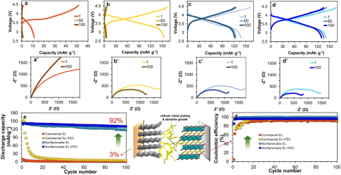
Figure 2. Voltage profiles of graphite∥NCM811 full-cell between 2.7 and 4.45 V with commercial EL (a) without and (b) with FEC additive and nonflammable EL (c) without and (d) with FEC additive, and their (a')–(d') impedance spectral evolution with 100 cycles under −10 °C. Comparison of (e) cycling performance and (f) Coulombic efficiency.
Download figure:
Standard image High-resolution imageReplacement of electrolyte to nonflammable one (Figs. 2c–2f) drives a dramatic performance improvement under −10 °C showing normal charge and discharge processes. This directly indicates the absence of lithium metal plating problem as illustrated in Fig. 2. The Coulombic efficiency of the first cycle under −10 °C, regardless of the presence of FEC additive, is 83%. While nonflammable electrolyte with FEC additive delivers the highest capacity 141 mAh g−1 and the highest cycling stability with capacity retention 92% after 100 cycles, the one without FEC additive delivers relatively lower capacity 137 mAh g−1 and lower capacity retention 87% but the highest Coulombic efficiency close to 100%. The calculated initial energy density of the full-cell with nonflammable electrolyte with FEC additive at 0.2 C under −10 °C is 551 Wh per kg of cathode active mass and the one without additive is 524 Wh per kg, in contrast to 18 Wh per kg with commercial electrolyte only. Those values are also significantly higher than that of graphite∥LiCoO2 conventional LIB that delivers capacity below 100 mAh g−1 (< 380 Wh per kg of cathode active mass) under subzero-temperature. 7 Such large increase in the energy density with nonflammable electrolyte system demonstrate a high applicability of our nonflammable electrolyte system to enable high-energy density and high-safety LIBs under subzero-temperatures.
In the impedance spectra, the semicircle(s) in mid-to high frequency region is attributed to the summed interfacial resistance of the SEI layers of cathode and anode. 21–23 Relatively smaller impedance rise of nonflammable electrolyte systems (Fig. 2c', 2d') should be correlated to significantly improved cycling performance and pertain to stabilized cathode-electrolyte and anode-electrolyte interfaces. For a basic understanding of the reasons for this electrolyte-driven huge difference in the performance under −10 °C, we conducted a mechanistic investigation of anodes and cathodes taken from the cycled full-cells. In general, under subzero-temperatures, the Li+ ion-diffusion through the surface and bulk of graphite anode might be all sluggish. Our focus thus lies on the in-depth investigation on what interfacial phenomena occur at the surface of graphite anode as well as NCM811 cathode under subzero-temperature and how to correlate to full-cell performance.
Graphite anode
Morphology changes of graphite anode
When we took a look at the particle morphology of the surface of anodes and cathodes after 100 cycles under subzero-temperature, more pronounced changes were found on graphite anodes than on cathodes. The millimeter-scale photo (Fig. 3b) of graphite anode cycled in commercial electrolyte exhibits somewhat non-uniform and rough surface with clearly distinguished bright and dark parts, compared to smooth surface of black pristine anode (Fig. 3a). Correlating to the abnormal cycling behavior above mentioned due to lithium metal plating (Fig. 2e), this visual non-uniformity confirms the presence of lithium metal plating. 24 Its SEM image (Fig. 3b') find a severely rough surface and cracks of graphite micro-particles. This morphology change can cause enlarged anode-electrolyte interfacial area and thus intensified reductive decomposition of electrolyte, detrimentally affecting the performance (Figs. 2a, 2e, 2f) and rising the impedance (Fig. 2a'). Upon the use of FEC additive (Fig. 3c), the photo of cycled anode shows improved uniformity, but clearly yellow and shiny lithium metal plated during subzero-temperature cycling. FEC additive plays a role in reducing particle morphology change in SEM image (Fig. 3c'), despite still the occurrence of unwanted lithium metal plating. This is associated with reduced impedance and its change (Fig. 2b'). By replacing the electrolyte with nonflammable one, the surface (Fig. 3d) of cycled anode becomes smooth like pristine, indicating no lithium metal plating. The image (Fig. 3d') finds a coverage of a graphite particle with newly produced surface species with tiny particles. The use of FEC additive also permits no lithium metal plating (Fig. 3e) and well-preserved particle morphology (Fig. 3e'). Newly produced surface species probably by electrolyte decomposition are clearly present. The stable cycling performance (Figs. 2e–2f) of nonflammable electrolyte systems under −10 °C is ascribed to the inhibition of lithium metal plating at graphite anode, significantly improved surface passivation with newly produced surface species and the preservation of particle morphology of graphite.
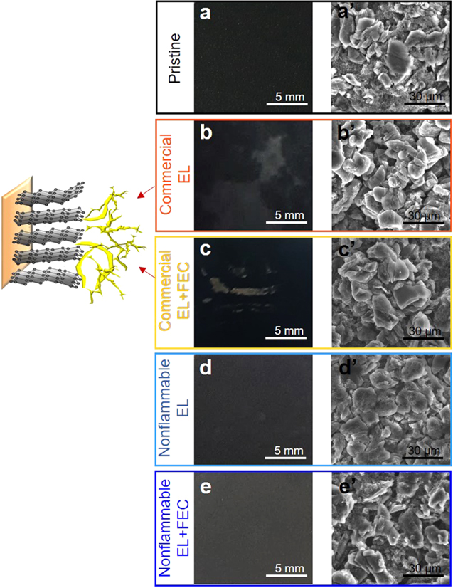
Figure 3. Photographs and corresponding SEM images of (a–a') pristine and cycled graphite anodes obtained from graphite∥NCM811 full-cells in commercial EL (b–b') without and (c–c') with FEC additive and nonflammable EL (d–d') without and (e–e') with FEC additive under −10 °C.
Download figure:
Standard image High-resolution imageStructural changes of graphite anode
Raman spectra in Fig. 4a provide information on structural changes of graphite with cycling under −10 °C. Pristine (Fig. 4a–i) shows a prominent peak of G-band at 1580 cm−1, attributed to E2g mode due to the in-plane vibrations of carbon atoms, and a trace of D-band at 1340 cm−1 corresponding to A1g mode due to the break of symmetry occurring at the edge planes and defects in the graphene sheets and structural disordering. 11,25–27 We utilize the intensity ratio of D-band (ID ) to G-band (IG ) as a measure of structural disorder. 11,25–27 The lower the ratio, the greater structural preservation. The ID /IG ratio (Fig. 4b) increases from pristine (0.096) to cycled anodes, due to structural disordering. The use of FEC additive in any electrolyte reduces the ratio in common, indicating improved structural preservation. The most structural disorder (i.e., the highest ratio) occurs by commercial electrolyte (0.350), whereas the least (i.e., the lowest ratio) by nonflammable electrolyte with FEC additive (0.168). This point emphasizes that the replacement of electrolyte to nonflammable one leads to significantly improved structural stability of graphite. It is surprising that electrolyte affects to the structure of graphite. In addition, the presence of a new band at 1617 cm−1 of D'-band (Fig. 4a) on all cycled anodes is an indication of surface defects. 11,28,29 As predicted, while D'-band is the strongest in commercial electrolyte, it is the weakest in nonflammable electrolyte with FEC additive. Relative strength of the D'-band is generally in the same tendency to the change in ID /IG . In commercial electrolyte, the occurrence of non-uniform lithium metal plating (Fig. 3b) along with interfacial reaction behavior at graphite anode might cause the structural disorder of graphite probably first at the local surface. Then the structural disorder is propagated to larger area of surface to near surface toward bulk during repeated cycling. The absence of lithium metal plating and the stabilized interface when using nonflammable electrolyte with FEC additive should be correlated to largely improved structural stability.
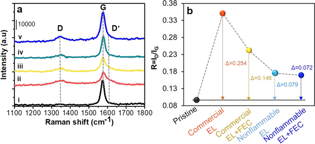
Figure 4. (a) Raman spectra and (b) R value of (i) pristine and cycled graphite anodes obtained from graphite∥NCM811 full-cells with commercial EL (ii) without and (iii) with FEC additive and nonflammable EL (iv) without and (v) with FEC additive under −10 °C.
Download figure:
Standard image High-resolution imageComposition changes of the SEI layer on graphite anode
ATR FTIR spectroscopy is a surface sensitive tool to probe qualitatively and quantitatively organic SEI species at the 500 μm depth from the electrode surface and on the electrode area of ≈12 mm2, which covers overall anode-electrolyte SEI formation behavior. Note that after washing with DMC, just stable solid precipitates remain at anode surface. Figure 5 exhibits IR spectra of pristine and cycled graphite anodes obtained from full-cells with nonflammable electrolyte without and with FEC additive under 4.45 V and −10 °C. Since unwanted lithium plating occurred at graphite anode in commercial electrolyte systems (Figs. 2a, 2b, Figs. 3b, 3c), we did not measure IR spectra for those to avoid the damage of a Ge IR optic by the reactive lithium metal. The IR spectra of cycled graphite anodes (Fig. 5a–iv, v) show prominent peaks at 2970–2910 cm−1 and 1460–1413 cm−1 attributed to methyl (CH3–) and methylene (–CH2–) groups of alkyl functionalities that come from newly formed surface species, in addition to carboxylic acid functionalities from PAA and CMC binders of pristine graphite (Fig. 5a–i). 4,7,11,21,22 Other commonly observed are peaks at 1740–1720 cm−1 due to νsym(C=O) of ester (RCO2R'; R,R' = alkyl group), which are confirmed by the peaks at 1270 cm−1 and 1160 cm−1 by ν(C−O−C)asym and ν(C−O−C)sym. Also commonly observed are peaks at 1650–1620 cm−1 of νsym(C=O) of alkyl carbonate salt ROCO2 −Mn+ (M = Li/Ni/Co/Mn) and those at 1570 cm−1 of νsym(C=O) of carboxylate salt RCO2 −Mn+. 7,21,23,24,30–36 Peaks at 1270–1250, and 1084 cm−1 are due to ν(C-F) from –CF3 and –CF2- functionalities that are of FEMC and DFDEC decomposition products. 7,32,37 A peak near 1470 cm−1 is due to ν(CO3)sym of Li2CO3, along with δ(CO3) at 850 cm−1, and peaks at 1320 and 1040 cm−1 of ν(P=O), ν(P−O−C)asym are of organic phosphorus fluorides (O=PF3–y(OR)y). 7,24,32–36 What is distinguished upon the use of FEC additive is relatively lower concentration of Li2CO3 and the presence of a tiny new feature at 1780 cm−1, attributed to poly(FEC) coming from FEC (Fig. 5a–v). 11,33,36,38
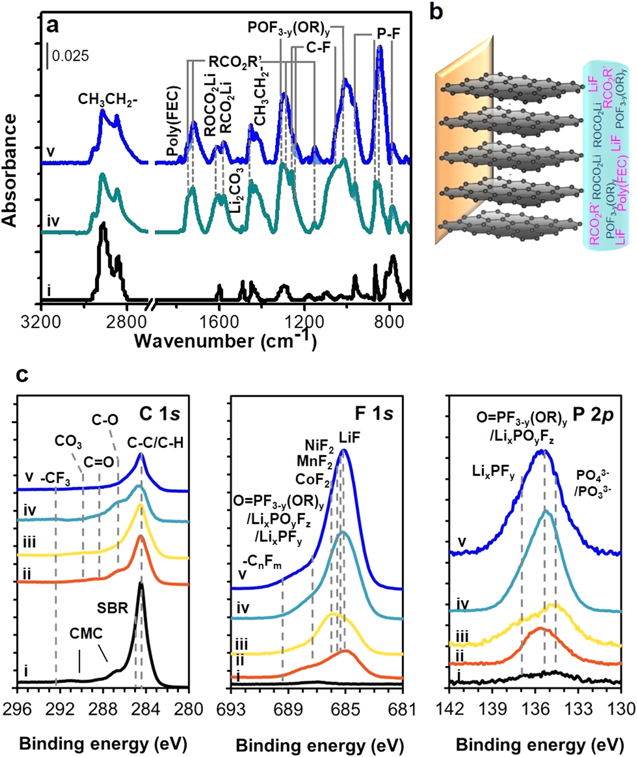
Figure 5. (a) ATR FTIR spectral comparison for graphite anodes and (b) schematic illustration of the SEI layer formation and composition, and (c) comparison for the C 1s, F 1s and P 2p XPS spectra of (i) pristine, and cycled graphite anodes obtained from graphite∥NCM811 full-cells with commercial EL (ii) without and with (iii) FEC additive and nonflammable EL (iv) without and with (v) FEC additive under −10 °C.
Download figure:
Standard image High-resolution imageThe SEI species are cross-checked with C 1s, F 1s and P 2p XPS spectra. In the C 1s spectra, after cycling (Fig. 5c–ii, iii, iv, v), new peaks of C–O at 286.8 eV, C=O at 288.3 eV and CO3 at 290 eV of organic compounds such as ester, alkyl carbonate salt and carboxylate salt are commonly observed, in addition to the major peak at 284.5 eV due to C–C/C–H coming from carbon black and the peaks of CMC and SBR binders of pristine graphite anode (Figs. 5c–i), which are consistent with O 1s spectra (Fig. S2a). 4,7,11,24,39,40 Upon the use of nonflammable electrolyte without and with FEC additive (Fig. 5c–iv, v), a trace of peak of –CF3, due to FEMC and DFDEC decomposition products, is observed near 292 eV, consistent with its presence at 688–689 eV in the F 1s spectra (Fig. 5c). 7,41 In the F 1s spectra, all cycled graphite anodes (Fig. 5c–ii, iii, iv, v) exhibit a dominant peak of LiF at 685 eV and a shoulder of LixPOyFz, LixPFy and/or organic phosphorus fluoride (O = PF3-y(OR)y) of LiPF6-derived species at 687.2 eV, as confirmed in the Li 1s (Fig. S2b) and P 2p spectra (Fig. 5c). 7,19,21,23,24,31–36,39,40 In particular, those features are significant in nonflammable electrolyte systems (Fig. 5c–iv, v), indicating the formation of F-based inorganics-rich SEI layer. The F 1 s spectrum of commercial electrolyte with FEC additive (Fig. 5c–iii) shows a strong peak of MnF2, NiF2 and CoF2 near 686 eV relative to the peak of LiF. 25,27,30,32–35 The presence of such deposits of metal species at graphite anode implies the occurrence of metal-dissolution from NCM811 cathode, which is discussed in later section.
The resultant data demonstrate the effects of nonflammable electrolyte and FEC additive in changing the SEI composition and concentration on graphite anode in full-cell under −10 °C; nonflammable electrolyte with FEC additive induces to form both organics-rich and inorganics-rich SEI layer, compared to that of commercial electrolyte systems. Superior cycling performance of full-cells in nonflammable electrolyte systems should be correlated to this effective surface passivation with the SEI layer. If metal-dissolution from cathode occurred in commercial electrolyte systems under −10 °C, that might another serious origin of performance failure in addition to lithium metal plating.
NCM811 cathode
Structural changes of NCM811 cathode
Electrolyte-induced bulk structural change in the NCM811 cathode with cycling under 4.45 V and −10 °C was examined using ex-situ powder XRD analysis as shown in Fig. 6. XRD pattern of pristine NCM811 cathode (Fig. S4–i) was identified as crystallized in hexagonal (R m) layered structure with the a and c lattice parameters of 2.8688 and 14.1989 Å, respectively, and the c/a ratio of 4.9495 and unit cell volume of 101.1951 Å3 (Fig. 6d).
24,42–44
After cycling in commercial electrolyte (Figs. 6a, 6b, 6c–ii), the peaks of (003), (101) and (104) reflections are largely shifted to higher 2θ region from that of pristine, causing a substantial decrease both in the a and c parameters (Fig. 6d). Such large peaks shift is attributed to the phase transformation from original hexagonal H1 phase to H3 as marked in the figures.
45,46
During charging (Li+-deintercalation), the H1 phase of NCM811 transforms to monoclinic phase (M) and hexagonal H2 phase and then another hexagonal H3 phase.
45,46
The presence of H3 phase, moreover, in the absence of H1 indicates a full phase transformation to H3 and severe structural disorder, despite cycling was ended as discharged. Note that the H1-to-H2 and H1-to-H2-to-H3 phase transformation during cycling is known to lead to a drastic lattice volume change, internal stresses and cracks along the grain boundaries.
47
This phase transformation and peaks shift to higher 2θ region are unusual phenomena that are observed only under subzero-temperature, which is distinguished from the commonly accepted tendency that the cycling of NCM active material in both half-cell and full-cell at room and elevated temperatures brings about the shift of (003) reflection to lower 2θ region.
48
As a result, with cycling under −10 °C and high voltage 4.45 V, the unit cell is subject to the isotropic abrupt contraction in both c- and a-directions (Figs. 6d, 6e) and never returns to its respective initial state. The crystal structure seems to freeze due to subzero-temperature condition and is not mechanically flexible probably. Peak broadening and weakening support structural disorder and the loss of crystallinity. The unit cell volume thus largely decreases by 5.3% (Fig. 6d), which is a notable difference from the cell volume reduction by just 0.4% occurred in nonflammable electrolyte system by anisotropic contraction only in a-direction. The formation of cracks in the primary NCM811 particles in commercial electrolyte (Fig. S3b) and a drastic performance failure just after 3 cycles (Fig. 2e) are in part ascribed to the significant and irreversible structural disorder and large volume change. The cracks generate enlarged cathode-electrolyte interfacial area and permits electrolyte penetration through the crannies, which accelerate the performance fade (Figs. 2a, 2e, 2f) and impedance rise (Fig. 2a'). Upon the use of FEC additive to commercial electrolyte (Figs. 6a, 6b, 6c–iii), the peaks of (003), (101) and (104) reflections are less shifted to higher 2θ region than those of commercial electrolyte only (Figs. 6a, 6b, 6c–ii). This is attributed to the structural transformation from H1 to H2 phase and still the occurrence of isotropic contraction in both c- and a-directions (Fig. 6e).
45,46
This is another unusual phenomenon observed only under subzero-temperature, which is distinguished from the co-existence of H2 phase with H1 phase on cycled NCM811 cathode in commercial electrolyte with 3 wt% FEC additive at room and elevated temperatures.
48
Relatively smaller unit cell volume reduction by 4.1% (Fig. 6d) is made upon the use of FEC additive. On the other hand, with cycling in nonflammable electrolytes systems (Fig. 6a–iv, v), the peak of (003) reflection is in common shifted to lower 2θ region from that of pristine, indicating lattice expansion in c-direction (Figs. 6d, 6e) while maintaining the original H1 phase of NCM811.
44
By the slight contraction in a-direction (Figs. 6b, 6c, 6d), unit cell volume increases just 0.12% from that of pristine. This improved structural maintenance should be correlated to reaction reversibility and improved performance. By using FEC additive to nonflammable electrolyte, the significantly improved structural stability is achieved; unit cell volume is maintained close to that of pristine (Fig. 6d). The ratio of peak intensity, R' = [I(102) + I(006)]/I(101)], was utilized as a relative measure of cation mixing and structural order by limiting to the H1 phase of NCM811 cathodes cycled in nonflammable electrolytes.
49,50
The cathodes cycled with commercial electrolyte systems that undergo an irreversible phase transition to H2 or H3 phase are thus excluded. The closer the R' value to that of pristine, the higher the structural stability. The R' (Fig. 6d) of pristine is 0.574, representing a good structural order referred to literatures.
49,50
After cycling with nonflammable electrolyte, R' slightly increases to 0.691 by structural change. With FEC additive, R' is near the value of pristine, ensuring higher structural stability, supporting the smallest unit cell volume change. These are interesting results to demonstrate how electrolyte composition influences the stability of bulk crystal structure of NCM811 active material by high-voltage cycling under −10 °C, and how the selection strategies of electrolyte and additive are critically crucial in achieving a high structural preservation and stable cycling performance.
m) layered structure with the a and c lattice parameters of 2.8688 and 14.1989 Å, respectively, and the c/a ratio of 4.9495 and unit cell volume of 101.1951 Å3 (Fig. 6d).
24,42–44
After cycling in commercial electrolyte (Figs. 6a, 6b, 6c–ii), the peaks of (003), (101) and (104) reflections are largely shifted to higher 2θ region from that of pristine, causing a substantial decrease both in the a and c parameters (Fig. 6d). Such large peaks shift is attributed to the phase transformation from original hexagonal H1 phase to H3 as marked in the figures.
45,46
During charging (Li+-deintercalation), the H1 phase of NCM811 transforms to monoclinic phase (M) and hexagonal H2 phase and then another hexagonal H3 phase.
45,46
The presence of H3 phase, moreover, in the absence of H1 indicates a full phase transformation to H3 and severe structural disorder, despite cycling was ended as discharged. Note that the H1-to-H2 and H1-to-H2-to-H3 phase transformation during cycling is known to lead to a drastic lattice volume change, internal stresses and cracks along the grain boundaries.
47
This phase transformation and peaks shift to higher 2θ region are unusual phenomena that are observed only under subzero-temperature, which is distinguished from the commonly accepted tendency that the cycling of NCM active material in both half-cell and full-cell at room and elevated temperatures brings about the shift of (003) reflection to lower 2θ region.
48
As a result, with cycling under −10 °C and high voltage 4.45 V, the unit cell is subject to the isotropic abrupt contraction in both c- and a-directions (Figs. 6d, 6e) and never returns to its respective initial state. The crystal structure seems to freeze due to subzero-temperature condition and is not mechanically flexible probably. Peak broadening and weakening support structural disorder and the loss of crystallinity. The unit cell volume thus largely decreases by 5.3% (Fig. 6d), which is a notable difference from the cell volume reduction by just 0.4% occurred in nonflammable electrolyte system by anisotropic contraction only in a-direction. The formation of cracks in the primary NCM811 particles in commercial electrolyte (Fig. S3b) and a drastic performance failure just after 3 cycles (Fig. 2e) are in part ascribed to the significant and irreversible structural disorder and large volume change. The cracks generate enlarged cathode-electrolyte interfacial area and permits electrolyte penetration through the crannies, which accelerate the performance fade (Figs. 2a, 2e, 2f) and impedance rise (Fig. 2a'). Upon the use of FEC additive to commercial electrolyte (Figs. 6a, 6b, 6c–iii), the peaks of (003), (101) and (104) reflections are less shifted to higher 2θ region than those of commercial electrolyte only (Figs. 6a, 6b, 6c–ii). This is attributed to the structural transformation from H1 to H2 phase and still the occurrence of isotropic contraction in both c- and a-directions (Fig. 6e).
45,46
This is another unusual phenomenon observed only under subzero-temperature, which is distinguished from the co-existence of H2 phase with H1 phase on cycled NCM811 cathode in commercial electrolyte with 3 wt% FEC additive at room and elevated temperatures.
48
Relatively smaller unit cell volume reduction by 4.1% (Fig. 6d) is made upon the use of FEC additive. On the other hand, with cycling in nonflammable electrolytes systems (Fig. 6a–iv, v), the peak of (003) reflection is in common shifted to lower 2θ region from that of pristine, indicating lattice expansion in c-direction (Figs. 6d, 6e) while maintaining the original H1 phase of NCM811.
44
By the slight contraction in a-direction (Figs. 6b, 6c, 6d), unit cell volume increases just 0.12% from that of pristine. This improved structural maintenance should be correlated to reaction reversibility and improved performance. By using FEC additive to nonflammable electrolyte, the significantly improved structural stability is achieved; unit cell volume is maintained close to that of pristine (Fig. 6d). The ratio of peak intensity, R' = [I(102) + I(006)]/I(101)], was utilized as a relative measure of cation mixing and structural order by limiting to the H1 phase of NCM811 cathodes cycled in nonflammable electrolytes.
49,50
The cathodes cycled with commercial electrolyte systems that undergo an irreversible phase transition to H2 or H3 phase are thus excluded. The closer the R' value to that of pristine, the higher the structural stability. The R' (Fig. 6d) of pristine is 0.574, representing a good structural order referred to literatures.
49,50
After cycling with nonflammable electrolyte, R' slightly increases to 0.691 by structural change. With FEC additive, R' is near the value of pristine, ensuring higher structural stability, supporting the smallest unit cell volume change. These are interesting results to demonstrate how electrolyte composition influences the stability of bulk crystal structure of NCM811 active material by high-voltage cycling under −10 °C, and how the selection strategies of electrolyte and additive are critically crucial in achieving a high structural preservation and stable cycling performance.
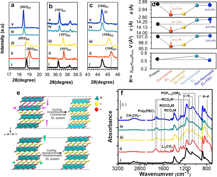
Figure 6. Powder XRD patterns of the reflections of (a) (003) and (b) (101) and (c) (104) planes of NCM811 cathodes obtained from graphite∥NCM811 full-cells with commercial EL (ii) without and (iii) with FEC additive and nonflammable EL (iv) without and (v) with FEC additive under −10 °C, and (d) the changes of lattice parameters, unit cell volume and R' value. (e) Schematic illustration of electrolyte-dependent structural change on NCM811 cathodes, and (f) electrolyte-dependent ATR FTIR spectral changes.
Download figure:
Standard image High-resolution imageWe investigated how electrolyte composition influences the SEI composition of NCM811 cathodes of full-cells with cycling under 4.45 V and −10 °C. Figure 6f compares the IR spectra of pristine and cycled NCM811 cathodes obtained after DMC washing. Pristine (Fig. 6f–i) shows prominent absorbance peaks at 1400, 1170 and 1072 cm−1, characteristic of PVdF binder. 7,8,21,23,24,30,32,34,36,51 The spectra of all cycled cathodes (Fig. 6f–ii ∼ v) exhibit in common the peaks at 2972–2908 and 1469–1411 cm−1 due to methyl (CH3–) and methylene (–CH2–) groups of alkyl functionality of PVdF binder and newly produced surface species. 24,30,47,48 Relatively stronger peak absorbance of alkyl functionality on the nonflammable electrolyte with FEC additive (Fig. 6f–v) is related to the presence of organic compounds with longer alkyl chain or at higher concentration than those of other electrolytes. Newly observed in common are the peaks at 1780–1770 and 1730 cm−1, of νsym(C=O) from various ester (−CO2R) compounds, which are confirmed with the peaks at 1278 and 1160 cm−1 by ν(C−O−C)asym and ν(C−O−C)sym. 7,21,23,24,30,32,34,36,50 Also commonly observed are new peaks at 1620 cm−1 and 1570 cm−1 of νsym(C=O) of alkyl carbonate salt ROCO2 −Mn+ (M = Ni/Co/Mn/Li) and carboxylate salt RCO2 −Mn+, respectively. 7,21,23,24,30,32,34,36,51 On the cycled cathode in commercial electrolyte (Fig. 6f–ii), a tiny peak near 1470 cm−1 is due to ν(CO3)sym of Li2CO3, which is a well-known EC decomposition product and observed in the Li 1 s XPS spectra (Fig. 7d). 7,32,50–52 Also newly observed are weak peaks at 1310–1010 cm−1 of ν(P=O) and ν(P–O–C)asym of POF3−y(OR)y and the ones at 918–780 cm−1 of ν(P–F) coming from PF-containing species like LixPFy, and LixPOyFz, which are typical decomposition products of LiPF6:EC solvate. 24 With FEC additive to commercial electrolyte (Fig. 6f–iii) or nonflammable electrolyte (Fig. 6f–v), a new tiny peak is observed at 1780 cm−1, attributed to poly(FEC) formed by FEC polymerization. 11,32,33,38 While cycled cathodes with nonflammable electrolyte without (Fig. 6f-iv) and with FEC additive (Fig. 6f–v) exhibit slightly stronger peaks of ester along with stronger peaks of alkyl groups than those of commercial electrolyte systems (Fig. 6f–ii, iii), implying higher concentration, alkyl carbonate salt and carboxylate salt are notably at lower concentration. New peaks at 1250, 1110 and 1084 cm−1, attributed to ν(C–F) of –CF3 and –CF2– functionalities, of nonflammable electrolytes might be of the decomposition products of FEMC and DFDEC. 24,34,36,51–53 The IR analysis results reveal that the surface of cycled NCM811 cathode in nonflammable electrolyte without and with FEC additive are covered with plenty of esters and CF-containing species, perhaps by oxidative decomposition of LiPF6:PC solvate, and FEMC and DFDEC solvents.
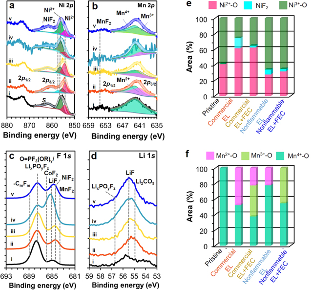
Figure 7. Comparison of (a) Ni 2p and (b) Mn 2p, (d) F 1s and (d) Li 1s XPS spectra for (i) pristine and cycled NCM811 cathodes obtained from graphite∥NCM811 full-cells with commercial EL (ii) without and (iii) with FEC additive and nonflammable EL (iv) without and (v) with FEC additive under −10 °C. Curve-fitting results for (e) Ni 2p3/2 peak and (f) Mn 2p3/2 peak.
Download figure:
Standard image High-resolution imageSurface chemical state of NCM811 cathode
Figure 7 presents XPS spectral comparison of the surface elements of NCM811 cathodes of full-cells before and after cycling under 4.45 V and −10 °C. The formation of soluble Ni2+–O and Mn2+–O at cathode surface has been established as a clear indication of metal-dissolution and oxygen gas release from NCM cathodes for maintaining a charge-neutrality and as surface structural degradation and reconstruction from hexagonal layered to disordered phase. 7,24,35 Earlier works showed that such surface structural change is propagated toward bulk, causing particle cracking and disintegration and impedance rise. 7,24,35 The lower the fraction of surface Ni2+–O and Mn2+–O on cycled cathode, the greater the maintenance of surface structure and morphology. 7,23,24,32–36 In the Ni 2p spectra of cycled cathodes (Fig. 7a), the asymmetric shape of 2p3/2 peak at 855 eV implies the mixed valence of Ni atom. Surface Ni valance was determined by curve-fitting on the 2p3/2 peak, which is separated from a shakeup satellite at 861.4 eV, employing multiple-splitting patterns derived from the standard compounds of NiO, Ni2O3 and NiF2 and at 854.2, 856.1 and 857.8 eV, respectively. 7,24,34,35,39–41 Fitting results are summarized in Fig. 7e. The surface of pristine (Figs. 7a–i and 7e) consists of 41% Ni2+–O and 59% Ni3+–O. After cycling in commercial electrolyte systems (Figs. 7a–ii,iii and 7e), the fraction of total surface Ni2+ (as Ni2+–O and Ni2+–F) largely increases to 75% and 64% without and with FEC additive, respectively. An increase in the fraction of surface Ni2+ with cycling is generally interpreted as the occurrence of electrochemical oxidation of electrolyte during charging (Li+-deintercalation), consequent electron transfer from electrolyte to surface Ni4+–O that forms during charging for charge-neutrality, and thus instant reduction of reactive surface Ni4+ to Ni3+ to Ni2+. 7,28,37 In the course of such surface reduction, some Ni2+ uptakes F− ion from electrolyte and forms a stable NiF2 as observed in the Ni spectra, 7,23,24,34–36,39–41,52 which is consistent with its presence in F 1 s spectra (Fig. 7c). However, such problematic soluble Ni2+–O formation is somewhat suppressed to 28% and 32% upon the use of nonflammable electrolyte without (Figs. 7a–iv and 7e) and with FEC additive (Figs. 7a–v and 7e), respectively. Cycling in nonflammable electrolyte system is ended as enriched surface state with Ni3+–O (Fig. 7e) that is closer to pristine, emphasizing the surface stabilization and passivation effect by nonflammable electrolyte. However, the concentration of LiF (Fig. 7d–iv, v), and CoF2 as well as NiF2 (Figs. 7c–iv,v and 7e) largely increase. 7,24,54 Upon the use of FEC additive, both commercial electrolyte and nonflammable electrolyte give in common the reduced fraction of NiF2 (Fig. 7e) together with LiF (Figs. 7c, 7d) and CoF2 (Fig. 7c), despite the expected role of FEC as an F-source. This in turn implies FEMC and DFDEC to be the F-sources but the dominant role of FEC additive to be a SEI forming agent on both NCM811 cathode and graphite anode.
Surface Mn valance was also determined by curve-fitting on the Mn 2p3/2 peak, employing multiple-splitting patterns derived from the standard compounds of MnO, Mn2O3 and MnO2 at 641.0, 641.7 and 642.7 eV, respectively. 7,23,24,33–36,39–41 Fitting results (Fig. 7f) reveal that 100% Mn4+–O of pristine surface is no longer maintained after cycling with any electrolyte. With commercial electrolyte (Figs. 7b–ii and 7f), 48% Mn2+–O forms at the expense of Mn4+–O. The electrochemical reduction of Mn4+–O to Mn3+–O followed by disproportionation of Mn3+–O to a half Mn4+–O and a half Mn2+–O might also occur in the course of electrolyte oxidation and electron transfer to surface Mn4+–O of NCM811 during charging. 7,23,24,33–36,41 A trace of MnF2 at 655.7 eV, confirmed with the peak at 685.5 eV in F 1 s spectrum (Fig. 7c–ii), indicates a possible interfacial reaction between Mn2+ and F− coming from electrolyte. 7,23,24,33,36,55 Upon the use of FEC additive (Figs. 7b–iii and 7f), three mixed valent Mn atoms of Mn4+–O, Mn3+–O and Mn2+–O coexist. The presence of Mn3+–O together with reduced fraction (22%) of Mn2+–O indicates suppressed MnO-dissolution. 30 The use of FEC additive (Figs. 7c–iii) brings about unchanged weak peak of MnF2 in F 1s spectrum, supporting the dominant role of FEC as the SEI forming agent for NCM811 cathode rather than a F-source for forming metal fluorides. On the other hand, nonflammable electrolyte (Figs. 7b–iv and 7f) drives greater maintenance of Mn4+–O to 78%, despite the formation of Mn2+–O at 22%. The use of FEC additive (Figs. 7b–v and 7f) leads to the absence of Mn2+–O, but just the presence of 55% Mn4+–O and 45% Mn3+–O. Cathodes display a shoulder at 688–689 eV due to C–F bond of FEMC and DFDEC-derived CF-containing species and a peak at 687.4 eV of LiPF6-derived POF3-y(OR)y/LixPOyFz species, consistent with P 2p spectra (Fig. S5c). 23,24,36
XPS analysis results reveal that nonflammable electrolyte induces to reduces the problematic surface Ni2+–O and Mn2+–O, which inhibits metal-dissolution and surface structural degradation of NCM811 under 4.45 V and −10 °C. Moreover, the use of FEC additive eliminates Mn2+–O at the surface of NCM811 cathode, leading to a further increase in the stability of surface chemical states of Ni and Mn. The SEI layer of NCM811 cathode is enriched with metal fluorides and LiF, compared to the case of commercial electrolyte.
Metal-dissolution phenomena
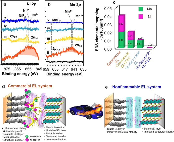
Metal-dissolution phenomena were identified by tracing the deposited metal compounds at the surface of cycled graphite anodes of full-cells under 4.45 V and −10 °C, as dissolved metal species are often transported through electrolyte and deposited at anode side. Figures 8a and 8b display XPS Ni 2p and Mn 2p spectra, respectively, for the surface of pristine and cycled graphite anodes. The spectral feature of Co 2p spectra are vague (Fig. S6). In commercial electrolyte without FEC additive, strong and broad peaks including Ni3+–O/Ni2+–O and NiF2 at 854–856 eV (Fig. 8a–ii), and Mn4+–O/Mn2+–O and MnF2 at 641.2–642.5 and 654 eV (Fig. 8b–ii), respectively, are observed. 7,23,24,36,39,40 These data prove the occurrence of metal-dissolution and deposition phenomena under −10 °C. The presence of deposited Ni and Mn compounds is examined with EDS elemental mapping results (Fig. 8c), which is a relative measure for the quantity of deposited metals. The presence of metal-deposits is subject to roughened surface of graphite anode, blocking of Li+ ion diffusion to graphite interlayers and unknown side reactions with electrolyte, impedance rise (Fig. 2a'), deleterious cycling performance (Fig. 2e). In addition to lithium metal plating, such surface degradation of cathode cause oxygen release along with electrolyte decomposition that causes an increase of gas pressure, leading to battery fire and EV fire as illustrated in Fig. 8d. With FEC additive (Figs. 8a–iii, 8b–iii), peaks of both metal-deposits are notably reduced, indicating reduced metal-dissolution. When using nonflammable electrolyte (Figs. 8a–iv and 8b–iv), the XPS features of both metal-deposits are negligible, consistent with EDS results (Fig. 8c). In nonflammable electrolyte with FEC additive, no metal deposit is shown in both XPS and (Figs. 8a–v, 8b–v) and EDS mapping results (Fig. 8c). This dictates that metal-dissolution and deposition phenomena are inhibited, due to the formation of stable SEI layers at both anode and cathode under 4.45 V and −10 °C as illustrated in Fig. 8e. Then, propagation of structural degradation from surface toward bulk is cut-off, and thereby, the bulk structure of both anode and cathode are stabilized. This is the key why the full-cell with nonflammable electrolyte with FEC additive outperforms the cell with commercial electrolyte and make the LIB safe, despite under high charge voltage and subzero-temperature.
Figure 8. Comparison of (a) Ni 2p and (a) Mn 2p XPS spectra of pristine and cycled graphite anodes obtained from graphite∥NCM811 full-cells with commercial EL (ii) without and (iii) with FEC additive and nonflammable EL (iv) without and (v) with FEC additive under −10 °C, and (c) their EDS elemental mapping results of deposited metal species. Schematic illustration of (d) metal-dissolution and deposition phenomena occurring in commercial EL system and (e) inhibited metal-dissolution but formation of stable SEI layers at both anode and cathode in nonflammable EL system.
Download figure:
Standard image High-resolution image
Conclusions
We demonstrate for the first time a lithium metal plating-free and metal dissolution-free graphite∥NCM811 full-cell even under subzero-temperature, despite high charge cut-off voltage of 4.45 V. While lithium metal-plating has been a threat to battery safety and lifespan of LIBs on subzero-temperature operation, which generally occurs in the early cycles of commercial electrolyte-based lithium-ion full-cells, the application of nonflammable electrolyte and furthermore with 3 wt% FEC additive under −10 °C enables the inhibition of lithium metal plating at graphite anode. This electrolyte also provides the formation of robust SEI layers at both graphite anode and NCM811 cathode, which inhibit metal-dissolution from cathode and structural degradation of anode and cathode from surface toward bulk and thereby lead to a good maintenance of their bulk structure. As a result, a lithium metal plating-free and metal dissolution-free full-cell with nonflammable electrolyte system enables the mitigation of all the failure modes of the full-cell with commercial electrolyte under subzero-temperature and unprecedented high capacity 141 mAh g−1 and high capacity retention of 92% over 100 cycles at 0.2 C. The results and discussion presented in this work offers a new opportunity and fine solution to the risks of battery fire and failure during subzero-temperature LIBs operation, which ultimately paves the way in the ubiquitous use of safer and well working LIBs despite under a cold timing and cold region.
Acknowledgments
This work was supported by the National Research Foundation grant funded by the Ministry of Science, ICT and Future Planning (2019R1A2C1084024) of Korea. The FE SEM was conducted at the National Nanofab Center, which is supported by the Nano·Material Technology Development Program through the National Research Foundation funded by the Ministry of Science, ICT and Future Planning (2009-0082580) of Korea. We thank Dr. Hieu Quang Pham for his help with experiments.