
Abstract
A solid-state lithium (Li) battery primarily consists of Li metal anode, solid electrolyte separator, and cathode. The asymmetric volume changes, originating from ion transport and interfacial Li growth during plating, lead to significant stresses in the layered architecture. In this study, we develop a coupled mechanics-electrochemistry formalism for polymer electrolyte based solid-state batteries, in particular, focusing on the stress effect on electrochemical performance. By means of a coupling coefficient, it is found that stress-assisted ion transport in the electrolyte results in a delayed Sand's time and increased critical current density of unstable electrodeposition, and consequently, alleviates the propensity of dendrite formation. Stress at the Li metal-electrolyte interface affects the electrochemical reaction kinetics, and the influences from the deviatoric stress and hydrostatic pressure vary with Li plating time. In addition, a low restraint stiffness to the layered structure could elastically buffer the volumetric changes and thus reduce the stress during Li plating. This fundamental study provides guidance for the design of solid-state batteries, aimed at stable electrodeposition and mechanical integrity.
Export citation and abstract BibTeX RIS
The burgeoning demand for energy storage has spurred the development of battery chemistries beyond lithium-ion in past years.1–5 Among them, solid-state metal (Li, Na, Mg, etc.) batteries have attracted tremendous interest because of their relatively high energy density and safety,6–9 of which the primary components are metal electrode, polymer or/and inorganic electrolytes, and cathode electrode. In the confined space of a solid-state battery, it is inevitable that stress is generated due to ion transport and electrochemical reactions. Compared to a liquid electrolyte system, the nature of solid-solid contact in solid-state batteries makes the release of stress more difficult. Therefore, understanding the underlying mechano-electrochemical coupling is conducive to improving battery performance.
Early studies have built the theoretical framework associated with the role of mechanics in chemical potential.10–12 Recently, it has been widely extended to the field of battery, which involves a stress-dependent ion transport. For instance, continuum models describing the coupling of stress and transport were developed for conventional Li-ion batteries,13–15 including Li-ion diffusion in electrode particles16,17 and electrode films.18–20 For solid-state Li batteries, the mechano-electrochemical coupling in the cathode electrodes was discussed, in particular, with the emphasis on the correlation between mechanical degradation and the durability of the battery.21,22
Mechanics could dominate the interfacial electro-chemo-mechanical behaviors between different layers in solid-state batteries. Dendrite at the Li metal-solid electrolyte interface is a big obstacle hindering the development of solid-state Li batteries, and thus, suppressing dendrite formation and growth has gained increasing attention.6,23–25 An earlier model demonstrated that the electrochemical potential difference across the electrode-electrolyte interface, caused by stresses, could suppress dendrite growth if the shear modulus of polymer electrolytes is large enough.26 This model was recently extended to address the influences of external pressure and electrolyte transport properties on dendrite growth between Li metal and polymer.27 For inorganic electrolyte based solid-state batteries, the suppression of dendrite growth was found to rely on surface morphology and fracture toughness of solid electrolytes.28 Delamination is another common issue occurring at the interface, and a pop-up interfacial delamination mechanism was revealed using a mechanical model.29
Previous studies focused on the levels of the electrode, solid electrolyte separator, and electrode-electrolyte interface separately. More recently, stresses were experimentally obtained at the battery level by the same group.30,31 However, theoretical research combining two electrodes and separator is still lacking. In this regard, we aim to develop a coupled model of mechanics-electrochemistry in a solid-state Li battery with polymer electrolytes in this study. Figure 1 illustrates a typical layered structure in solid-state batteries. During Li plating, the cathode electrode shrinks due to delithiation, whereas Li metal electrode expands due to electrodeposition. Thus, the asymmetric volume changes of the two electrodes produces stress in the layered structure during plating. In turns, stress at the Li metal-electrolyte interface modifies the electrochemical reactions kinetics.32 Moreover, polymer electrolyte separator plays a key role in ion transport that directly affects electrodeposition performance, and stress can regulate ion transport in the polymer electrolyte. Thus, electrodeposition stability correlates with the mechano-electrochemical coupling, which is the focus in this study. Our fundamental work provides insights into the design of solid-state Li batteries aimed at high performance, which could be also applied to the batteries based on other metal electrodes.

Figure 1. Schematic of Li plating in a solid-state battery, consisting of the anode (Li metal), polymer electrolyte separator, and cathode. The green layer is newly formed Li. The coordinate origin is set at the interface between the separator and the newly formed Li, with the y-axis in the film thickness direction (horizontal direction), and the interface is movable during plating. On the left and right boundaries, iappl is the applied current density. The displacement U1 is zero on the left boundary, and the displacement U2 = σyy/K on the right boundary. K represents the buffering effect on the multilayer structure. For example, if the right boundary is fixed (U2 = 0), K = +∞.
Download figure:
Standard image High-resolution imageGoverning Equations
In this section, the governing equations for solving ion concentration, electric potential, and stress are presented. Given that diffusion induced volume strain of the cathode electrode can be directly given in terms of the applied current density and time, Li-ion transport in the cathode is not considered. Herein, Li-ion transport in the polymer electrolyte separator and Li plating at the electrode-electrolyte interface are focused on. For mechanics, the polymer electrolyte separator and cathode electrode are assumed to undergo linear elastic deformations, whereas Li metal has an elastic-plastic strain due to its low yield stress.33 The above assumption is valid for relatively stiff polymer electrolyte with a large yield strain of elasticity.34–36 Subsequently, the coupled model of mechanics-electrochemistry is applied to a one-dimensional (1D) problem under constant current condition.
Li-ion transport in the polymer electrolyte separator
Common lithium salts include LiPF6, LiClO4, and LiTFSI. Thus, monovalent ions are assumed to exist in the polymer electrolyte below. The flux of cations (Li+) and anions (denoted by X−) can be given by37,38


On the right-hand side, the first term describes the ion diffusion, and the second term represents the ion migration under electric field, which are consistent with the Nernst-Planck equation used in electrochemical systems.39 The third term represents the pressure gradient-driven flux, and the previous theoretical studies have demonstrated that the pressure gradient has an impact on ion flux through polymer electrolytes.37,38 It should be noted that if the Nernst-Einstein equation D = μRT is used, Eqs. 1 and 2 can be rewritten to the forms of those in previous studies.37,38 D+ (D−) is the diffusion coefficient of Li+ ion ( ), c+ (c−) is the molar concentration of Li+ ion (
 ), u+ (u−) is the mobility of Li+ ion (
 ), Ω+ (Ω−) is the partial molar volume of Li+ ion (
 ) in the polymer electrolyte,
  is the electric potential, F is the Faraday's constant, and pE is the hydrostatic stress in the polymer electrolyte calculated from the stress tensor σE

According to the Nernst–Einstein equation, the mobility is related to the diffusion coefficient by
where R is the gas constant and T is the temperature.
If the solution is assumed to be electrically neutral, we have

Using the above equation, the electrical current density is given as
Upon the substitution of Eq. 6 into Eqs. 1 and 2 by eliminating the potential gradient, it can be deduced
Where


D is the electrolyte diffusion coefficient, ΩE is the partial molar volume of LiX in the polymer electrolyte, and t+ is the transference number, which represents the capability of current transport carried by Li+ ions.
In the polymer electrolyte, there is no production of Li+ ions. Thus, the accumulation of cations is caused by the net flux, which is expressed as

Substituting Eq. 7 into Eq. 12, we have

For the conservation of charge, it gives

If the transference number is independent of Li-ion concentration, the substitution of Eq. 14 into Eq. 13 yields

where
It should be noted that in addition to Eq. 12, the mass conservation of anions can lead to the same equations in 13 and 15.
The current density in Eq. 6 can be rephrased to
Where
κ is the concentration-dependent conductivity, and κD is diffusion-induced conductivity. In the framework of concentrated solution theory, κD is modified as
where  is the mean activity coefficient of the electrolyte.39 Thus, the governing equation of charge transport in the electrolyte can be obtained by substituting Eq. 17 into Eq. 14
Interface
At the two electrolyte-electrode interfaces, the flux of anions is zero, which requires that
Meanwhile, the current density is equal to the applied current density

At the Li metal-electrolyte interface, the electrochemical potential difference in the electrons, induced by stress, is expressed by Ref. 26
where  is the surface energy, en is the unit vector normal to the interface, ΔpLi and ΔpE are the pressure changes of Li metal and polymer electrolyte at the interface, and the deviatoric stress tensors is defined as

The electrical potential across the Li-electrolyte interface takes the form

where ULi is the equilibrium potential, η is the overpotential on the Li metal surface. Using Eq. 25, the modified Butler–Volmer equation for the electrochemical reaction kinetics is thus deduced as32
Where iBV is the current density generated by the electrochemical reactions at the Li-electrolyte interface, ka and kc are the anodic and cathodic rate constants, and α and β are the corresponding charge transfer coefficients.
Mechanics
Given that mechanical deformation is much faster than ion transport, the mechanical equilibrium equation reads

The constitutive equation of the polymer electrolyte is

where εE is the strain tensor, δ is the Kronecker delta, and ME is a forth-order tensor of elastic constants. In the regime of isotropic linear elasticity, we have
Where EE and vE are the Young's modulus and Poisson's ratio of the polymer electrolyte, and I is the identity tensor.
In Eq. 28,  is the eigenstrain caused by ion concentration change, which is described as
where VE is the volumetric change and c0 is the initial ion concentration.
For the cathode electrode, the constitutive equation is the same as the one in Eq. 27. For the Li metal anode, the constitutive equation is written as

where the strain is comprised of elastic strain and plastic strain. For the elastic deformation, the elastic constant tensor is expressed in terms of the Young's modulus ELi and Poisson ratio vLi
Assuming that plastic deformation does not produce the volume change of Li metal, the trace of the plastic strain tensor is equal to zero, i.e.

For the threshold of plastic deformation, the yield surface is defined as

where Y is a scalar function of plastic deformation history related to the current yield surface, which can be expressed as

where Ep is physically interpreted as the plastic modulus, and  is the effective plastic strain, defined as
Using the von Mises criterion, J2 flow theory of plasticity gives the yield function
where J2 is the second stress invariant, related to the deviatoric part of stress tensor

According to the consistency condition derived from Eq. 37, it can be deduced that
where h designates a scalar parameter. Equation 39 builds the relationship between the plastic strain increment and the stress increment.
If the left boundary is fixed in Fig. 1, we have the mechanical boundary conditions in the y-axis direction


where U1 and U2 are the y-axis displacements on the left and right boundaries, respectively,  is the stress in the y-axis direction, and K is defined as the external stiffness which represents the buffering effect on the deformation of the multilayer structure.
Application to 1D Problem
In this section, the above model is applied to the layered structure in solid-state Li batteries, as shown in Fig. 1, which could be simplified to a one-dimensional (1D) problem. First, ion concentration in the polymer electrolyte separator is numerically solved. Then, the electric potential and stress can be analytically obtained.
Decoupled ion transport equation
For the Li metal, polymer electrolyte separator, and cathode electrode, the thickness of each layer is much smaller than the other two dimensions. Hence, we assume that Li-ion flux and electric field are along the y-axis direction (thickness direction), and that


If the two interfaces between electrodes and separator are intact, without delamination and slip, 
 and
and  are the three principal stresses in each layer. In our macroscale model, interfacial excess stress between Li metal and polymer electrolyte separator is not considered.40
In the thickness direction, the equilibrium equation of 27 implies that  is constant, which follows that

For the polymer electrolyte, the substitution of Eqs. 42 and 43 into the constitutive equation of 28 leads to

Thus, the solution of the mechanical problem could also be reduced to the y-axis direction, which is addressed in the sub-section of 3.2.
Because of the constant  in Eq. 45, we have

Although σyy is constant, the pressure gradient exists in the y-axis direction through the polymer electrolyte separator due to the varying stresses of σxx and σzz. Equation 48 indicates that the pressure gradient is proportional to the Li-ion concentration gradient in the y-axis direction. Upon the substitution of Eq. 48 into Eq. 15, we have

where

θ is a non-dimensional parameter, named as the coupling coefficient in this study. Correspondingly, the boundary condition of Eq. 21 is rewritten as

For the initial condition, ion is uniformly distributed through the polymer electrolyte

Upon the substitution of Eq. 48 into Eq. 17, we have
As a result, Li-ion concentration distribution in the polymer electrolyte separator can be directly obtained from Eqs. 49, 51 and 52. Then, the electric potential is analytically solved from Eq. 53. Because of the pressure effect on ionic flux in Eqs. 1 and 2, the coupling coefficient is present in Eqs. 49 and 53, which indicates that pressure gradient could affect the distributions of ion concentration and electric potential in the polymer electrolyte.
In this work, the effects of pressure on electrochemical performance have two aspects. First, Eq. 1 or Eq. 48 shows that the pressure gradient affects ionic transport, which has been demonstrated in previous studies.37,38 Second, Eqs. 23 and 26 shows that pressure affects electrochemical reaction kinetics, which has been addressed in previous studies.27,32
Solution for mechanics
In the following, the analytical solution of stress is provided, focusing on the stress component in the y-axis direction.
From the constitutive equation, the y-axis strain in the cathode electrode is

For the polymer electrolyte separator, we have the strain in the y-axis direction as

Li metal has an elastic-plastic strain, and the parameter Y in Eq. 34 needs to be first determined from uniaxial tensile test. For simplicity, the linear isotropic hardening model is used. Thus, the yield stress can be expressed as
Where 
 and Et are the plastic strain, the initial yield stress, and the post-yield tangent modulus from the stress-strain curve in uniaxial tensile test. Substituting Eq. 56 into Eq. 37 and noting that
  deduced from Eq. 36, we have

where the plastic modulus Ep = ELiEt/(ELi−Et).
The Li metal in Fig. 1 has a stress state of (

 ). Using Eqs. 37 and 43, we obtain

Using Eqs. 31, 33, 57, 58, we can deduce that
Thus, the y-axis strains in the three layers are expressed in terms of the stress  In the y-axis direction, we have the compatibility of deformation from Eq. 41

where lLi, lE, and lC are the thicknesses of the Li metal, polymer electrolyte separator, and cathode electrode, respectively, K is the stiffness applied to the layered structure, and l0 is the thickness of the newly deposited Li. For a rigid constraint to the structure, K is infinite. The coordinate origin is set at the Li metal-separator interface, which is movable during plating.
At a time of t, it readily follows that

Substituting Eqs. 54, 55, and 59 into Eq. 60, it gives
where
Other stress components can be obtained from the constitutive equation. For the deduction of Eq. 62, two equations are used

The first equation implies that ion transport in the polymer electrolyte separator does not induce a thickness change in the y-axis direction when the average ion concentration is kept at c0. In contrast, ΔlC0 in Eq. 66 is the thickness shrinkage of the cathode electrode because of delithiation.
Equation 62 holds when Li metal is subject to elastic-plastic strain. If no plastic strain is generated in Li metal, and C1 and C2 are revised to

A special situation is that the thickness increased in Li metal is equal to the thickness decreased in cathode electrode, i.e.

Then, all the stress components in Li metal are zero, and the polymer electrolyte separator and cathode electrode are not subject to the stress in the y-axis direction. Conversely,  is generated when Eq. 68 is not satisfied.
Some Results and Discussion
As mentioned in the above section, ion concentration in the polymer electrolyte separator is can be numerically solved for the layered structure. Using the ion concentration profile, the electric potential and stress can be analytically obtained.
If the mechano-electrochemical coupling is neglected, i.e. the coupling coefficient θ = 0, the system can maintain a maximum current density, which is deduced from Eq. 51

 is the limiting current density widely used in the literature. Here, we introduce the non-dimensional current density

Furthermore, we introduce the non-dimensional ion concentration, coordinate, and time
Thus, the governing Eq. 49, the boundary condition 51, and the initial condition 52 can be rewritten in the non-dimensional forms. Unless otherwise indicated, the material parameters in Table I are used, leading to a coupling coefficient of θ = 0.3.
Table I. Parameters for a special example.
| Parameters | Values | Units | |
|---|---|---|---|
| E | Young's modulus: Li | 9 | GPa |
| Polymer electrolyte | 330 | MPa | |
| Cathode | 10 | GPa | |
| v | Poisson's ratio: Li | 0.42 | |
| Polymer electrolyte | 0.24 | ||
| Cathode | 0.3 | ||
| Ω | Molar volume: Li | 1.3 × 10⁻⁵ | m3 mol−1 |
| Polymer electrolyte | 1.0 × 10⁻⁴ | m3 mol−1 | |
| Cathode | 3.0 × 10⁻⁶ | m3 mol−1 | |
| l | Layer thickness: Li | 25 | μm |
| Polymer electrolyte | 15 | μm | |
| Cathode | 60 | μm | |
| c0 | Bulk electrolyte concentration | 1.5 × 10³ | mol m−3 |
| D | Diffusion coefficient | 2.7 × 10¹² | m2 s−1 |
| α (β) | Charge transfer coefficients | 0.5 (0.5) | |
| t+ | Transference number | 0.3 | |
| ka | Anodic rate constant | 9.832 × 10⁻⁶ | mol m−1 s−1 |
| kc | Cathodic rate constant | 9.832 × 10⁻⁶ | m2 s−1 |
| σs | Initial yield stress of Li metal | 0.4 | MPa |
| Et | Post-yield modulus of Li metal | 0.9 | GPa |
| K | External stiffness to the structure | +∞ | MPa μm−1 |
| R | Gas constant | 8.314 | J mol−1 K−1 |
| F | Faraday constant | 96,487 | C mol−1 |
| T | Operating temperature | 293 | K |
Figures 2a and 2b show the profiles of ion concentration and x-axis stress in the polymer electrolyte separator under χ = 0.5 at two times, respectively. Two cases are considered: θ = 0 (without stress effect on ion transport) and θ = 0.3. In comparison to the case of θ = 0, ion concentration is more uniform for θ = 0.3, leading to a relatively smaller concentration gradient. It indicates that stress can facilitate ion transport in the electrolyte. At the time of  = 0.6, ion concentration reaches the steady state. For θ = 0, the concentration is linearly distributed in the thickness direction, forming a constant gradient. For θ = 0.3, the concentration gradient continuously decreases along the y-axis direction in a gentle way, which can be confirmed by Eq. 49. Corresponding to the ion concentration distribution, non-linear
  distribution is generated at the time of
  = 0.03 in Fig. 2b. For the two cases, the stress is always asymmetrical in the polymer electrolyte separator.
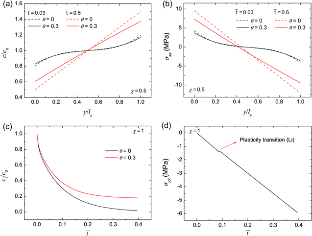
Figure 2. For the polymer electrolyte separator, (a) the Li-ion concentration distribution in the y-axis direction and (b) stress in the x-axis direction under the non-dimensional current density of χ = 0.5, and the evolution of (c) Li-ion concentration at the Li-polymer electrolyte interface and (d) stress in the y-axis direction under the condition of χ = 1. For the case of θ = 0, stress effect on ion transport is neglected.
Download figure:
Standard image High-resolution imageFigures 2c and 2d show the concentration  at the Li metal-electrolyte interface and y-axis stress
  with time under the non-dimensional current density χ = 1. As time increases, the interface concentration decreases and approaches a steady-state value. For θ = 0, the interface concentration will eventually approach zero, whereas the interface concentration will be larger than zero for the case of θ = 0.3. Figure 2d shows the evolution of stress
  consisting of two stages. The transition distinguishing the two stages occurs at a very early plating stage. In the second stage, Li metal experiences elastic-plastic deformation. It can be seen that the stress linearly varies with time, which is in good agreement with previous studies.30,31 For instance, it was observed that the stress in the thickness direction approximately has a linear relationship with time for all-solid-state batteries.31
To further explore the mechano-electrochemical coupling, Fig. 3 shows the dependence of the coupling coefficient on transport characteristics. Sand's time is the required time for ion depletion in the vicinity of the electrode-electrolyte interface. Physically, ion concentration is reduced to zero when t > tSand, and the system could not support the applied current due to diffusion limitation in the electrolyte. For θ = 0, Sand's time is expressed as41
Using Eqs. 68–72, we have the non-dimensional Sand's time
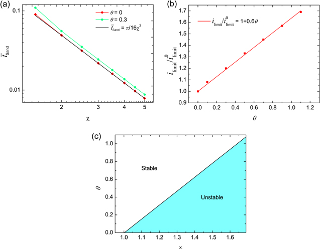
Figure 3. (a) Log-log plot of dimensionless Sand's time with increasing dimensionless current density, where the black line is the theoretical prediction for θ = 0 without stress effect on ion transport. (b) Critical current density with varying coupling coefficient θ. (c) Phase map of electrodeposition stability in terms of χ and θ.
Download figure:
Standard image High-resolution imageIn the case of θ = 0, Fig. 3a shows that the calculated Sand's time is consistent with the theoretical prediction by Eq. 73. In contrast, Sand's time is delayed for θ = 0.3. Delayed Sand's time helps to avoid dendrite formation during electrodeposition, which indicates that stress could increase the onset time of ion transport-driven instability at high currents. In addition, a linear trend is shown in the log-log plot for Sand's time and the current density, which is in good agreement with that of earlier experiments.42
Figure 3b illustrates the limiting current density with varying coupling coefficient, which demonstrates that a stronger mechano-electrochemical coupling leads to a higher limiting current density. It is evident that a higher critical current density could suppress the tendency to dendrite formation. Correspondingly, Fig. 3c shows the phase map of electrodeposition stability. For θ = 0, unstable electrodeposition is caused when the non-dimensional applied current density χ ≥ 1. Increasing the coupling coefficient enhances the stability, pushing unstable electrodeposition to the stable regime, and the line depicts the transition boundary for the two regimes. Thus, stress could improve electrochemical performance by increasing the threshold of applied current to initiate dendrite formation and subsequent penetration through the separator.
Figure 4a shows the dimensionless surface overpotential on Li metal surface under χ = 0.5, which is calculated by using iappl = iBV. Equation 26 indicates that the overpotential relies on the ion concentration  and stress induced electrochemical potential difference
  at the electrode-electrolyte interface. In Fig. 4b, the two effects are compared for θ = 0 and θ = 0.3, which provides the reason why the overpotential is lower for θ = 0.3. Figures 4c and 4d explain the trend of the overpotential with time. In the early stage of plating, the overpotential dramatically increases, primarily attributed to the interface concentration decrease in Fig. 4c. Even after the interface concentration
  reaches a steady-state value, the overpotential still has a very gentle increasing trend with time, which is completely due to the decreasing
  with time in Fig. 4d. For the flat electrode-electrolyte interface, the contribution from surface energy is zero, and Eq. 23 is reduced to
Thus,  consists of two terms, originating from the deviatoric stress and the hydrostatic pressure at the interface, respectively. Their effects are illustrated in Fig. 4d, where the green circle denotes the plasticity transition of Li metal. Deviatoric stress always induces a positive electrochemical potential difference
  which contributes to reducing the overpotential
  in Fig. 4a. In contrast,
  caused by hydrostatic pressure continues to decrease with time after an initial increase. By comparing the two slopes when
  > 0.4, it can be concluded that the total
  decreases with time, which accounts for the gentle increasing trend of
  in Fig. 4a.
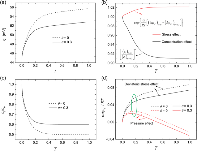
Figure 4. (a) Overpotential on Li metal surface under the condition of χ = 0.5. (b) Comparison of stress effect and concentration effect on the overpotential between θ = 0 and θ = 0.3. (c) Evolution of Li-ion concentration at the Li-polymer electrolyte interface. (d) Stress induced electrochemical potential difference with time.
Download figure:
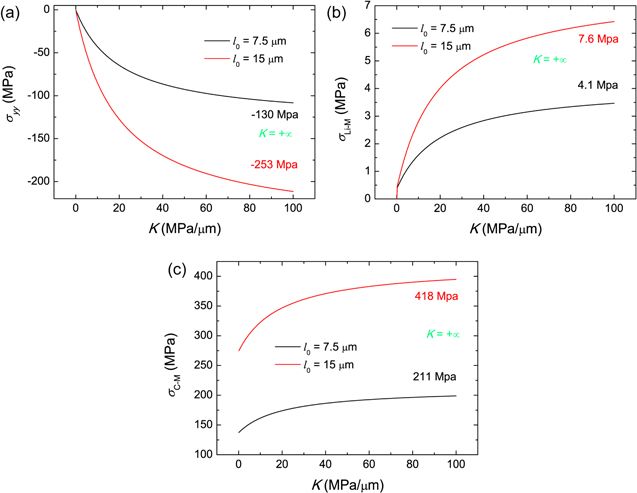
Standard image High-resolution imageFigure 5 shows the K-dependent stresses. A larger K denotes a higher external elastic stiffness to the layered structure. The extreme of K = +∞ represents a rigid constraint, and the corresponding stresses are given in Fig. 5. As expected, the compressive stress  in the thickness direction increases and converges to the value for K = +∞. Hence, a flexible constraint can buffer the volumetric changes of two electrodes. Two electrodeposition thicknesses are considered, i.e. l0 = 7.5 μm and l0 = 15 μm, and Fig. 5a indicates that the stress for l0 = 15 μm is almost twice that of the case l0 = 7.5 μm, which complies with the linear trend in Fig. 2d.
Figure 5. External stiffness dependence of stress, with two electrodeposition thicknesses considered, i.e. 7.5 μm and 15 μm. (a) Stress in the y-axis direction. (b) von Mises stress in Li metal film. (c) Average von Mises stress in the cathode electrode.
Download figure:
Standard image High-resolution image
For Li metal and the cathode electrode, von Mises stress  is used
The von Mises stress in Li metal is uniform, while it varies in the cathode electrode along the y-axis direction due to non-uniform Li-ion concentration. Here, the average von Mises stress is calculated for the cathode electrode. To obtain the average von Mises stress, the average stresses in the x-axis and z-axis directions are deduced as
Figures 5b and 5c illustrate the von Mises stresses in Li metal and the cathode electrode, respective. Figure 5b demonstrates that Li metal only undergoes elastic deformation when K is very small. Because of the plastic strain, the von Mises stress in Li metal for l0 = 15 μm is lower than twice of the stress for l0 = 7.5 μm. Figure 5c shows that the von Mises stress in cathode electrode decreases with decreasing K. The elastic stiffness K directly releases the y-axis stress  in our model, while the second term in Eq. 76 is independent of K. Therefore, the dependence of K on the von Mises stress in cathode electrode is not as strong as that in Fig. 5a.
The aforementioned results demonstrate the importance of mechanics in solid-state batteries. A larger coupling coefficient θ improves electrochemical performance, resulting in a higher limiting current density, a longer Sand's time, and a lower surface overpotential on Li metal, which contribute to the suppression of dendrite formation due to transport limitation. Based on Eq. 50, strategies towards the increase of θ include: increasing the Young's modulus EC, bulk ion concentration c0, partial molar volume ΩC, and Poisson's ratio  From a mechanics standpoint, a flexible constraint to the layered structure can release the volumetric changes of electrodes and thus reduce stresses, which helps to avoid mechanical failures in solid-state batteries. In this work, the role of mechano-electrochemical coupling in suppressing the onset of dendrite formation is discussed under the assumption that Li plating is uniform at the electrode-electrolyte interface. However, uneven Li plating, originating from spatial heterogeneity, allows for a curved growing interface, and the role of mechano-electrochemical coupling in suppressing dendrite growth will be our future focus.
In our model, the key assumptions are summarized below.
- (1)The model is developed for binary solutions under the framework of dilute solution theory, in which migration is independent of diffusion, as indicated in Eqs. 1 and 2. For concentrated solutions, the equation for ion flux needs to be modified to consider the interactions between diffusing ions, while the equations for mass balances, current flow, and electroneutrality remain valid for concentrated solutions.39
- (2)The film thicknesses of the Li anode, separator, and cathode are assumed to be much smaller than the sizes in other dimensions, i.e. the x-axis and z-axis directions in our model. Thus, the strain components are assumed to be 0 in the x-axis and z-axis directions, while the stress components exist in those two directions. If the film thickness is comparable to the sizes in other dimensions, Eq. 42 will be affected.
- (3)The linear isotropic hardening model is used for the elastic-plastic behavior of Li metal anode. During plastic deformation, the yield stress is assumed to linearly varies with the strain based on a previous experiment.33
- (4)The cathode is assumed to be a uniform and isotropic electrode. Given that we aim to develop a model at the macroscale, the microstructure of cathode is not considered. Thus, our model could not describe the physical field and electrochemical behavior of various phases in the composite electrode.
Conclusions
In summary, a coupled model of mechanics-electrochemistry is developed for polymer electrolyte based solid-state batteries during Li plating, aimed at addressing the mechanism of stress tuned electrochemical performance. In the confined space of battery, the volumetric changes of two electrodes generate significant stresses in the Li metal film, solid electrolyte separator, and cathode electrode. For the polymer electrolyte separator, stress is found to enhance ion transport, resulting in a delayed Sand's time and increased critical current density, which contributes to averting the formation of Li dendrite formation, and this effect can be described by a dimensionless coupling coefficient. Stress at the Li metal-electrolyte interface is demonstrated to affect the electrochemical reaction kinetics, and the influences on the overpotential are different for the two parts from deviatoric stress and hydrostatic pressure. In addition, the external stiffness applied to the layered structure also determines the value of stress generated during Li plating, and a low stiffness can effectively buffer the volumetric changes. This fundamental study underlines the role of mechanics in the electrochemical performance of solid-state batteries, which provides guidance for the battery design towards stable electrodeposition and robust layered structure.
Acknowledgments
The information, data, or work presented herein was funded in part by the Office of Energy Efficiency and Renewable Energy (EERE), U.S. Department of Energy, under Award DE-EE0007766, and Purdue University faculty research grant.