

Abstract
Rational design of cost-effective and high-efficiency nonprecious oxygen evolution reaction (OER) catalysts for electrochemical water-splitting towards the commercialization of renewable energy conversion technologies remains challenging. Herein, a facile one-step reduction method is proposed to fabricate three-dimensional (3D) amorphous NiCoFe catalysts with nanowires@nanosheets (NiCoFe NW@NSs) core–shell nanostructures. The unique 3D and amorphous features can accelerate the transfer process of relevant active species and provide more accessible active sites. Coupled with synergistic effects resulting from the ternary metals and core–shell nanostructures, the as-prepared Ni1Co1Fe1 NW@NSs exhibits the ultralow overpotential of 220 mV at the current density of 10 mA cm−2 and Tafel slope of 36.42 mV dec−1, which is superior to the benchmark RuO2 catalyst (290 mV and 127.93 mV dec−1). Furthermore, the catalyst displays remarkable long-term stability with negligible degeneration of only 9 mV after 24 h chronopotentiometry test. This work provides insight into the rational design of catalysts to achieve intrinsically high activity and stability in the alkaline electrolyte for water-splitting devices.
Export citation and abstract BibTeX RIS
The exhaustion of traditional energy and environmental pollution make it urgent to develop sustainable and renewable energy sources.1–4 Among them, hydrogen with the metrics of high energy density (140 MJ·kg−1) and absolute eco-friendly is recognized as the long-sought-after candidate to occupy the new energy fields, which could be efficiently produced by electrochemical water-splitting.5 Unfortunately, the sluggish anodic kinetics of oxygen evolution reaction (OER), hinders the electrolysis of water to produce hydrogen. Therefore, to produce clean energy through the water splitting, the primary task is to reduce the overpotential of the OER reaction by developing more high-efficiency catalysts. To date, the state-of-the-art catalysts are noble metals and corresponding oxides, such as Ir- or Ru- based compounds, but the scarcity and high price of them undoubtedly restrict their applications. Thus, extensive researches are devoted to developing earth-abundant nanomaterials.6–10 Accordingly, nonprecious metal catalysts become the promising alternatives due to their low cost, earth abundance and excellent OER activity.11–15
One of the most promising transition-metal-based catalysts for OER is the NiFe-based electrocatalyst,16–20 which possesses high intrinsic activities with impressive low overpotential due to the partial-charge-transfer activation effect for Ni with the addition of Fe.21,22 However, it is acknowledged that the NiFe-based catalysts also encounter some bottlenecks, such as poor conductibility and low stability.23 Besides hybridizing them with conductive supports,1,24,25 tuning their own structures and components for increasing the number of active sites and boosting the reactivity of the active sites have aroused great attention. Most works focused on the straightforward approach to introduce other metal elements into NiFe-based catalysts, such as Co,26 Al,17,27 Ce28 and Cu.29 Due to the modulated electronic structures of the catalytic centers and electronic conductivity, the heterogeneous NiFe-based catalysts revealed unexpected OER performances. Apart from constructing functional multimetallic nanostructures, it's worth mentioning that morphological control is also critical in the pursuit of high catalytic activity.30 Notably, three-dimensional (3D) structures have been considered as the most effective morphology to improve the OER activity of nonprecious metal-based catalysts.31,32 3D porous structures cannot only facilitate electron transportation and promot electrolyte penetration, but also offer large surface areas.33–35 Moreover, the introduction of the amorphous structure with abundant surface defects and lattice defects can facilitate the exposure of active sites with under-coordinated metal atoms to further prompt the OER activity of catalysts, which showed superior performances compared to their crystalline counterparts.36,37 Additionally, the unique amorphous structure can endow the catalysts with ultrahigh stability by reducing the destruction of the active sites through the fast mass transfer process.38 Although great achievements have been made in the development of robust NiFe-based catalysts, accurate design and synthesis of more advanced catalysts integrated with multiple advantages in terms of morphology and components are still demanded, ultimately achieving our goal of improving sluggish OER in electrochemical water splitting.
Herein, a facile one-step NaBH4 reduction method was proposed to precisely regulate the formation process of NiCoFe catalyst. Due to the dynamic control, the 3D amorphous NiCoFe catalyst with unique nanowire@nanosheets core–shell structuers (NiCoFe NW@NSs) can be completed within 5 min (Figure 1A). Because of the characteristic structural and compositional features, the optimized Ni1Co1Fe1 NW@NSs exhibits favorable OER activity with an overpotential of only 220 mV to deliver the current density of 10 mA cm−2, super to that of commercial RuO2 catalyst (290 mV). Another typical feature lies in the splendid stability with the neglectable recession of 9 mV after 24 h chronopotentiometry test. Due to the simple synthetic strategy along with the potential for large-scale production, the newly designed NiCoFe NW@NSs hold great promise in water splitting and other energy-related applications.
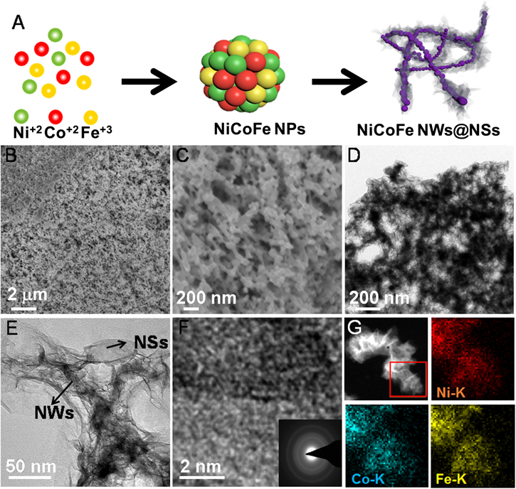
Figure 1. (A) Schematic illustration of the synthesis of NiCoFe NW@NSs. SEM (B) and (C), TEM (D) and (E), HRTEM images (F) and EDS mapping (G) of Ni1Co1Fe1 NW@NSs. F inset: SAED pattern of Ni1Co1Fe1 NW@NSs.
Download figure:
Standard image High-resolution imageExperimental
Materials
NiCl2·6H2O, CoCl2·6H2O, FeCl3·6H2O and NaBH4 were purchased from Aladdin reagent. RuO2 catalyst was purchased from Alfa Aesar. All other reagents were analytical-reagent grade. Deionized water used in all experiments with a resistivity of 18.2 MΩ·cm was obtained by treatment with a Milli-Q water purification apparatus (Millipore, MA, USA).
Synthesis of Ni1Co1Fe1 NW@NSs
The Ni1Co1Fe1 NW@NSs with 3D porous structures were synthesized via efficient one-step reduction by NaBH4. Briefly, 1 ml precursor solution with 0.1 M of total metal ions (Ni2+: Co2+: Fe3+ = 1: 1: 1) was rapidly injected into 5 ml 0.1 M NaBH4 solution with vortex stirring at room temperature. The product would converge quickly together after 5 min with the solution became clarified. After freeze-drying, Ni1Co1Fe1 NW@NSs was obtained. Similarly, other NixCoyFez (n(Ni2+): n(Co2+): n(Fe3+) = x: y: z) catalysts with different molar ratios were prepared by a similar procedure except for the feed ratio of metal ions in the precursor.
Characterization
The morphology of each catalyst was investigated by using scanning electron microscopy (SEM) on Quanta FEG250 field-emission environmental SEM (FEI, USA) at a working voltage of 5 kV. Transmission electron microscopy (TEM) images were investigated by Philips CM200 UT (Field Emission Instruments, USA) at JEOL JEM-2010 microscope at a working voltage of 200 kV. STEM-EDS elemental mapping analysis was determined on a JEOL-2100F transmission electron microscope at an acceleration voltage of 300 kV. X-ray diffraction (XRD) patterns were characterized in the 2θ range of 30°–80° using a D8 ADVANCE (Bruker, Germany) and the tube was operated at 40 kV and 40 mA. X-ray photoelectron spectroscopy (XPS) characterization was performed with a Physical Electronics Quantera Scanning X-ray Microprobe to determine the compositions and valence states of the elements in the catalyst. The actual molar ratio of catalysts was carried out by the inductively coupled plasma-optical emission spectrometer (ICP-OES, Agilent 8800). BET surface area was measured using N2 adsorption/desorption at 77 K on a Micromeritics TriStar II. All electrochemical data was from a CHI 660E electrochemical workstation (Shanghai CH Instruments, China) and the Faraday efficiency was tested in CHI 760E electrochemical workstation (Shanghai CH Instruments, China) at room temperature.
Electrochemical experiments
A traditional three-electrode system was used in the electrochemical experiment, in which the rotating disc electrode (RDE), platinum foil and saturated calomel electrode (SCE) were chosen as the working electrode, counter electrode and reference electrode, respectively. Prior to the surface coating, RDE was polished with 1.0, 0.3 and 0.05 μm alumina powder, respectively, rinsed and sonicated with deionized water and dried under nitrogen. The catalyst was dispersed into the mixtures of water, isopropanol, and Nafion (v:v:v= 4:1:0.1) with the mass fraction of 2 mg ml−1, followed by the ultrasonic dispersion for 30 min. The loading of all catalysts on the RDE was 0.2 mg cm−2, followed by the drying before the electrochemical performance test.
The electrochemical experiments were performed in the 1.0 M KOH solution at a scan rate of 5 mV s−1. As for the linear sweep voltammetry (LSV)curves, the test voltage ranged from 0 to 1 V (vs SCE) and the measured voltage was converted to a reversible hydrogen electrode (RHE) scale by a formula of ERHE = ESCE + 0.059*pH + 0.2415, and the overpotential (η) was calculated according to the following formula: η(V) = ERHE −1.23 V. During the LSV, RDE was continuously rotated at the speed of 1600 rpm to remove the generated bubbles. Cyclic voltammetry (CV) curves were measured with different scan rates (2, 4, 6, 8, and 10 mV s−1) in the voltage range of 1.065–1.115 V without any redox process to evaluate the electrochemical double-layer capacitance (Cdl) as shown in Eq. 1:

where CDL is the specific capacitance of the electrode double layer (F/cm2). The electrochemically active surface areas (ECSA) was calculated as Eq. 2:

Cs is the specific capacitance and reported to be between 0.022 to 0.130 mF cm−2 in the alkaline solution. In this study, we use the value of Cs is 0.040 mF cm−2 based on previously reported Ni-based OER catalysts.
The Faradaic efficiency (FE) can be given as Eq. 3:
where ir and id are the measured ring and disk currents, respectively, and N (0.37) is the collection efficiency of the rotating ring disk electrode (RRDE).
EIS was tested to observe the charge-transfer resistances on the interfacial. Chronopotentiometry curves were tested at the given η where the initial current density is 10 mA cm−2 to evaluate the long-term stability.
Results and Discussion
The morphology of fabricated Ni1Co1Fe1 NW@NSs (the feed molar ratio of Ni, Co and Fe is 1:1:1) was firstly characterized by scanning electron microscopy (SEM). As shown in Figure 1B, 3d porous nanofoam structures can be first identified. Further observation in Figure 1C indicates that 3D structures are linked by amounts of tiny nanowires, which are generally favorable for the mass transfer process during OER. Meanwhile, the bimetallic catalysts (Ni1Fe1, Ni1Co1 and Co1Fe1 NW@NSs) and other NiCoFe catalysts with different ratios (Ni1Co8Fe1, Ni1Co1Fe8 and Ni8Co1Fe1 NW@NSs) were also prepared and characterized by SEM (Figure S1 and S2 is available online at stacks.iop.org/JES/167/064514/mmedia). Similar to Ni1Co1Fe1 NW@NSs, 3D network structures can be also identified for the above-mentioned catalysts. Furthermore, the transmission electron microscopy (TEM) image of Ni1Co1Fe1 NW@NSs shown in Figure 1D illustrates the interconnected nanowires features. Clearly, these nanowires with 10–20 nm diameter are distinctly coated with abundant silk-like ultrathin nanosheets on the surface from the high-magnification TEM (Fig 1E). Typically, this unique morphology can be ascribed to the characteristic forming process (Figure 1A). Initially, the metal precursors are reduced and linked together to form NiCoFe nanoparticles (NiCoFe NPs) rapidly by kinetic controlling. Then, the NiCoFe NPs can further fuse to NiCoFe nanowires (NiCoFe NWs), followed by evolving into 3D self-supported nanoframes. Simultaneously, the partial surface of nanowires can be hydrolyzed into NiCoFe hydroxides shaping with lamellar nanosheets, which were different from precious metal-based product (such as Au, Pt and Pd) due to the sluggishness of oxidation.39,40 Especially, the metal hydroxides are usually regarded as active species of OER.30 The TEM images of binary catalyst and other NiCoFe NW@NSs are shown in Figure S3 and S4. It is found that only slight lamellar nanosheets can be observed for other NiCoFe catalysts, which implies the limited content of these active hydroxide species. Notably, the amorphous feature of Ni1Co1Fe1 NW@NSs is clearly revealed in the high-resolution TEM (HRTEM) image where no obvious crystal lattice can be identified according to Figure 1F. The corresponding selected area electron diffraction (SAED) pattern of Ni1Co1Fe1 NW@NSs also exhibits only amorphous halos without any clear light spot (inset of Figure 1F). The amorphous features are conducive to the electron transport as well as high exposure of reactive sites and thus considered as the ascendant structures for OER. Energy-dispersive spectroscopy (EDS) mapping analysis shown in Figure 1G illustrates the homogeneous distribution of Ni, Co and Fe without any phase separation. The element composition of Ni1Co1Fe1 NW@NSs was confirmed by EDS (Figure S5). In addition, the inductively coupled plasma-optical emission spectrometer (ICP-OES) analysis suggests a 3:1:2.47 atomic ratio of Ni, Co and Fe for Ni1Co1Fe1 NW@NSs and the other catalysts are also shown in Table SI.
Further investigation of X-ray diffraction (XRD) was performed to analyze the crystallinity and phase information of Ni1Co1Fe1 NW@NSs. As shown in Figure 2A, the diffraction pattern shows a broad amorphous hump at the range of 40° ∼ 50°, manifesting the amorphous features of the Ni1Co1Fe1 catalyst, which is consistent with the SAED image. According to Figure S6, other NiCoFe NW@NSs with different atomic ratios are similar to Ni1Co1Fe1 NW@NSs with broad diffraction. The Brunauer–Emmett–Teller (BET) analysis was also carried out to characterize the 3D porous structure of Ni1Co1Fe1 NW@NSs (Figure 2B). The BET surface area was calculated as 28.71 m2 g−1. Moreover, the pore size distribution in the inset of Figure 2B indicates the presence of both micropores and mesopores, which are beneficial for mass transport between the pores and the bulk solution. X-ray photoelectron spectroscopy (XPS) was conducted to analyze the surface chemistry and electronic structure of the Ni1Co1Fe1 NW@NSs. Figure 2C reveals the existence of Ni, Co, Fe and O species. Especially, there still exists a trace of B and C elements which are derived from the NaBH4 during the synthesis process and CO2 in the air, respectively.41 The high-resolution XPS spectrum of Ni 2p shows in Figure 2D can be divided into three major spin–orbit doublets. The first doublet is located at 875.69 eV (Ni 2p1/2) and 858.06 eV (Ni 2p3/2), which is attributable to Ni3+. The second doublet is located at 873.27 eV (Ni 2p1/2) and 855.36 eV (Ni 2p3/2), which is considered as Ni2+. The peaks of 869.07 eV (Ni 2p1/2) and 852.28 eV (Ni 2p3/2) are identified as Ni0, named as the third doublet. Similarly, 2p1/2 and 2p3/2 peak can be also observed in the high-resolution XPS spectra of Co and Fe shown in Figure 2E and 2F, containing metal state and oxidation state.42,43 The oxidation states of three metal elements indicated the existence of metallic (oxy)hydroxides at the surface of catalysts, playing a critical role in boosting OER performance.36
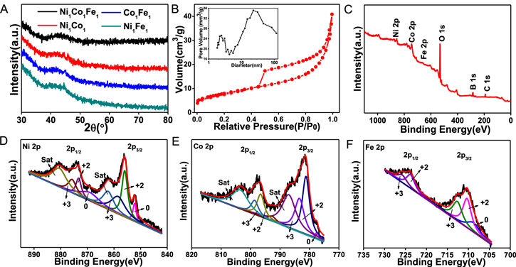
Figure 2. (A) XRD patterns of Ni1Co1Fe1, Ni1Co1, Co1Fe1 and Ni1Fe1 NW@NSs. (B) N2 adsorption isotherm and corresponding pore size distribution. (C) XPS spectrum of Ni1Co1Fe1 NW@NSs. High-resolution XPS spectra of Ni (D), Co (E), and Fe (F) of Ni1Co1Fe1 NW@NSs.
Download figure:
Standard image High-resolution imageIn order to investigate the OER activities of NiCoFe NW@NSs, a typical three-electrode system in 1.0 M KOH solution saturated with N2 was adopted. The NiCoFe NW@NSs catalysts with different ratios were firstly optimized (Figure 3a and Figure S7). It is known that the current density of 10 mA cm−2 is a standard to evaluate the OER catalytic activity.44 According to LSV curves, Ni1Co1Fe1 NW@NSs delivers the lower potential of 1.45 V at the current density of 10 mA cm−2 compared to other NiCoFe NW@NSs catalysts, which illustrates the intrinsic activity of Ni1Co1Fe1 NW@NSs is superior to other catalysts.15 Actually, the much predominant lamellar hydroxide nanosheets of Ni1Co1Fe1 NW@NSs from TEM images can demonstrate the abundant active species compared to other ratios of catalysts. Particularly, Ni1Co1Fe1 NW@NSs also exhibits much lower potential than the benchmark RuO2 catalyst (1.52 V) and binary NW@NSs (1.48 V, 1.54 V, 1.52 V for Ni1Fe1, Ni1Co1 and Fe1Co1 NW@NSs, respectively) at the current density of 10 mA cm−2. Remarkably, η of 270 mV is achieved even though at the large current density of 100 mA cm−2, while the higher overpotentials are required for binary NW@NSs (310 mV for Ni1Fe1, 410 mV for Ni1Co1 and 360 mV for Fe1Co1 NW@NSs), testifying the superiority of the ternary catalysts derived from the synergistic effect.45
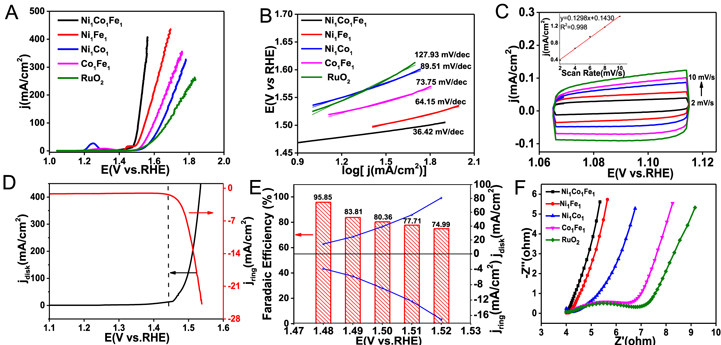
Figure 3. LSV curves (A), Tafel plots (B) of Ni1Co1Fe1, Ni1Co1, Co1Fe1, Ni1Fe1 NW@NSs and RuO2. (C) The double-layer capacitance measurements of Ni1Co1Fe1 NW@NSs by measuring cyclic voltammograms in a non-Faradaic region at different scan rates. The inset shows a plot of the anodic current measured at 1.09 V as a function of scan rate. (D) RRDE measurement of Ni1Co1Fe1 NW@NSs at a rotation speed of 1,600 rpm (ring potential: 0.2 V). (E) The Faradaic efficiency and the disk/ring currents of RRDE plotted as a function of the applied disk potential. (F) Nyquist plots of EIS of Ni1Co1Fe1, Ni1Co1, Co1Fe1, Ni1Fe1 NW@NSs and RuO2. All tests were carried out at 1.0 M N2-saturated KOH solution.
Download figure:
Standard image High-resolution imageTo gain further insights into intrinsic activities, the kinetic process was evaluated by Tafel plots (Figure 3B and S7). Ni1Co1Fe1 NW@NSs shows the ultralow Tafel slope of 36.42 mV dec−1, indicating the favorable intrinsic activity of Ni1Co1Fe1 NW@NSs in comparison to Ni1Fe1, Fe1Co1, Ni1Co1 NW@NSs with Tafel slope of 64.15, 89.51, 73.75 mV dec−1, respectively. The electrochemical capacitance of the electrode-electrolyte interface in Cdl was also tested through CVcurves under different scanning rates to estimate ECSA (Figure 3C and Figure S7C). The ECSA and Cdl of the various catalysts in this study are given in Table I and Table SII. The ECSA value of Ni1Co1Fe1 NW@NSs is much higher than those of binary NW@NSs catalysts, indicating the distinct enlargement of ECSA after the cooperation of Ni, Co and Fe.
Table I. Electrochemical parameters of Ni1Co1Fe1, Ni1Co1, Co1Fe1, Ni1Fe1 NW@NSs and RuO2 in 1.0 M KOH solution saturated with N2.
| Catalyst | E at j = 10 mA cm−2 (V) | η at j = 100 mA cm−2(mV−1) | Tafel slope (mV dec−1) | Cdl (mF cm−2) | ECSA (cm2) |
|---|---|---|---|---|---|
| Ni1Co1Fe1 | 1.45 | 270 | 36.42 | 4.68 | 117 |
| Ni1Fe1 | 1.48 | 310 | 64.15 | 1.47 | 36.75 |
| Ni1Co1 | 1.54 | 410 | 89.51 | 1.26 | 31.5 |
| Co1Fe1 | 1.52 | 360 | 73.75 | 0.074 | 1.85 |
| RuO2 | 1.52 | 440 | 127.93 | 0.020 | 0.5 |
To analyze the evolved gas during the OER process, the RRDE was tested with the aid of electrochemical reduction. Notably, the evolved O2 can be reduced by Pt ring held at a potential of 0.2 V. As shown in Figure3D, when the disk potential was swept past 1.45 V (onset potential of Ni1Co1Fe1 NW@NSs), the distinct lift of the cathodic ring current derived from oxygen reduction reaction (ORR) indicated that the bubbles formed at the anode were indeed O2. Furthermore, FE of OER was also determined. As shown in Fig. 3e, the highest FE was obtained to be 98.73% at the disk potential of 1.5 V, and decreased to 46.72% with the disk voltage increasing to 1.55 V. This decrease can be attributed to apparently large amounts of undissolved oxygen bubbles generated at the relatively high disk potentials which might not be efficiently collected by the Pt ring electrode. Thus, the high FE of OER for Ni1Co1Fe1 NW@NSs indicates the excellent yield of O2.
In order to further explore the factors affecting the electrochemical activity, the corresponding electrochemical impedance spectrum (EIS) were examined to explore charge-transfer resistance (Rct). As shown in Figure 3F and S7D, Ni1Co1Fe1 NW@NSs exhibits the lowest semicircle in the low-frequency range. The smallest Rct for electron transfer also confirms the outstanding OER intrinsic activity, which may root in the improved conductivity for the 3D amorphous features as well as the synergy of Ni, Co and Fe. It is reported that the incorporation of Co can greatly improve the electronic conductivity of NiFe-based catalyst and facilitate electron transport as well as the proton migration of the NiFe-based hydroxide.46
For an excellent electrochemical catalyst, not only the electrochemical activity is an important indicator for evaluation, but the long-term stability is a key factor to be considered.47 Hence, the chronopotentiometry test was performed to appraise the stability of Ni1Co1Fe1 NW@NSs. As illustrated in Figure 4A and 4B, in comparison to the commercial RuO2 catalyst, Ni1Co1Fe1 NW@NSs shows a rather insignificant increase trend of voltage (9 mV) at a fixed current density (10 mA cm−2) for as long as 24 h, maintaining the good stability of Ni1Co1Fe1 NW@NSs. As depicted in Figure 4C, there are no clear collapses and aggregates of the structures after the test. Moreover, there is no significant change of distribution of Ni, Co and Fe compared with the distribution before the test, proving the morphology stability (inset of Figure 4C). On the one hand, the 3D porous nanowires structures can increase the exchange of liquid reactants as well as gas products and the amorphous feature also can boost the mass transfer process, which may reduce the destruction of intrinsic activity sites. On the other hand, the XPS analysis after the chronopotentiometry test shown in Figure 4D–4F demonstrates a distinct positive shift of Ni, Co and Fe peaks, indicating the increase of oxidation states after a long time chronopotentiometry test, and this obvious shift can be ascribed to the increasing contents of NiOOH, CoOOH and FeOOH. Notably, NiOOH is usually considered as the active sites and the increase of oxidation state signifies the transform from Ni(OH)2 to NiOOH, which is conducive to the high activity. Meanwhile, the presence of Fe4+ is regarded to enhance the electron-donating ability among maintaining the oxidized Ni and the bridging oxygen atoms.48 In addition, the change from Co(OH)2 to CoOOH is proved to not only enhance the conductivity and the proton migration process of NiOOH, but decrease the corrosion of NiOOH.26 Therefore, the valence state change of metal species during the chronopotentiometry test is proved to benefit to the OER performance. In brief, the extraordinary combination of 3D and amorphous feature, as well as the multimetallic nanostructures, cooperatively boosts the OER stability.

Figure 4. (A) Chronopotentiometry curves of various catalysts at a fixed current density of 10 mA cm−2. (B) the potential comparison of various catalysts before and after chronopotentiometry test. TEM image (inset: EDS mapping) (C) and the comparison of high-resolution XPS spectra of Ni (D), Co (E), Fe (F) of Ni1Co1Fe1 NW@NSs after chronopotentiometry test.
Download figure:
Standard image High-resolution image
To sum up, the superior OER activity and stability of Ni1Co1Fe1 NW@NSs can be attributed to the following factors. i) 3D porous features provide the catalysts with stable frameworks to hinder the morphology change. In addition, it can benefit the exposure of active sites and make it easier for the diffusion of liquid reactants and gas products. ii) The amorphous defects produced by coordinated metal atoms can greatly expedite the binding of adsorbate as well as the exposure of active sites. iii) The incorporation of Co into NiFe-based catalyst changes the electronic structure, thereby increasing the conductivity and reducing the corrosion of NiOOH. Therefore, the performance of Ni1Co1Fe1 NW@NSs is superior to most of the reported non-noble metals catalysts according to Table SIII.15,33,43,44,49–55
Conclusions
In summary, 3D amorphous NiCoFe catalysts were fabricated through a facile one-step method. Due to the various improvements such as conductivity and mass transfer rates derived from 3D amorphous features and synergies of multiple metals, the optimized Ni1Co1Fe1 NW@NSs delivers an outstanding OER performance with the overpotential of 220 mV at the current density of 10 mA cm−2, even better than commercial RuO2 catalyst. The super stability was also reflected with only 9 mV recession after 24 h chronopotentiometry test. The excellent catalytic activity and stability of the Ni1Co1Fe1 NW@NSs illuminate the great application prospect of the integrated conception of reasonable incorporation for the 3D amorphous features as well as the synergies of multiple metals. Our synthesis strategy for the energy catalysts will open a new avenue to reduce the high cost of industrial commercial noble-metal catalysts and realize mass production.
Acknowledgments
The authors gratefully acknowledge the financially supported of the Fundamental Research Funds for the Central Universities (CCNU19QN066), the Program of Introducing Talents of Discipline to Universities of China (111 program, B17019) and the Recruitment Program of Global Youth Experts of China.