Abstract
The influence of the electrolyte solvents on the cell voltage in lithium-sulfur (Li-S) batteries is investigated. It is found that changing the solvent does not only alter the reaction mechanisms taking place during charge and discharge, but also exerts a pronounced influence on the cell voltage. The changes monitored upon switching from standard ether-based electrolytes to more polar solvents are quite substantial. An increase in the open circuit voltage of up to ∼400 mV could be observed. Both experimental evidence and theoretical calculations are presented in order to elucidate and quantify these effects. It is demonstrated that both the observed trends and the order of magnitude of the measured values can be explained by the free solvation energies of the respective ionic species in the electrolyte systems. Among them, the lithium cation contributes most to the phenomena described. Given that the final reaction products are solid and precipitate from the solution, these effects cannot be exploited to increase the overall energy densities of standard Li-S batteries. However, they are still important both with respect to the fundamental understanding of the electrochemical processes involved as well as practical applications such as liquid, polysulfide-based redox flow batteries.
Export citation and abstract BibTeX RIS
Li-S cells are among the most promising next-generation post-Li-ion battery systems, due to their high specific charge and discharge capacities and energy densities (theoretically 1675 mAh/g and 3518 Wh/kg, respectively, based on the sulfur active material).1–5 However, their practical breakthrough is hampered by several challenges such as loss of active material and growth of dendritic structures on the metallic lithium anode as well as continuous decomposition of the electrolyte.2,6,7 In spite of many elegant experimental approaches and impressive progress which could be achieved with respect to cycling stability and cell performance (2,8–21, to name just a few examples), none of the systems presented was able to address all of the problems mentioned above.
Elucidating the electrochemical reactions taking place and their subtle interplay in this battery type is therefore of crucial importance for the development of tailor-made solutions for the above-mentioned issues and the improvement of the cell performance. The electrochemical charge and discharge reactions of the sulfur active material itself are key issues for these considerations.
In addition to the numerous experimental challenges involved in the technical realization of this battery system, one principal disadvantage is the substantially lower discharge voltage, which in average amounts to approximately 2.1 V and therefore only to roughly 50–60% of the value of current state-of-the-art Li-ion batteries.2,22 Achieving higher voltages, however, is an advantage not only because of the simultaneous gain in energy density but also because in many cases technical applications require a certain overall voltage of a battery. Increasing the voltage of individual cells means that fewer cells are necessary to be incorporated into a battery pack and therefore less packaging and support material is necessary, which in turn means another gain in energy density for the overall system.
Parameters critically important for achieving satisfactory cycle lives in Li-S batteries include the sulfur content, electrode designs as well as the electrolytes and contents used.23–27
State-of-the art electrolytes for Li-S batteries are mostly based on mixtures of dioxolane with dimethoxyethane or other ethers, as they are both chemically stable against attack of the highly nucleophilic polysulfide intermediates formed in the course of discharging the battery and reasonably stable against the metallic lithium usually used as anode in this battery system.3,28–30 Moreover, they show a high solubility for the intermediate polysulfide species while maintaining a low enough viscosity to support the electrochemical reactions taking place at the electrodes. Additives such as nitrate salts provide a protective layer on the metallic lithium anode suppressing the otherwise detrimental polysulfide shuttle.31,32 This shuttle mechanism roots in the fact that the polysulfide intermediates formed electrochemically can diffuse in the electrolyte back and forth between the two electrodes and undergo electrochemical reactions. This leads to a very low coulombic efficiency of this battery type and a quick loss of active material.
In ether-based electrolytes, typically two discharge plateaus are observed upon cycling a Li-S cell: One at ∼2.3–2.4 V, corresponding to the formation and reduction of long-chain polysulfides down to medium chain lengths (Li2S4), contributing overall about 25% to the overall discharge capacity and another one at lower voltages around 2.1 V, accounting for the remaining 75%.28,33,34
It is well-known that the sulfur chemistry depends heavily on the chemical environment, which in this battery system predominantly means the electrolyte.7,35–41
Pioneering theoretical and experimental contributions based on different techniques helped to shed light on the complicated reaction chemistry and mechanisms taking place within an Li-S cell upon electrochemical cycling and the formation of the respective intermediates.42–47
However, not only the reaction pathways at play might change together with the solvent and electrolyte system under consideration, but also the chemical state of the reaction products, namely solvated lithium ions and polysulfide species. This solution-based reaction chemistry is one important difference between Li-S and standard Li-ion battery systems, in which intercalation electrodes play the role of the hosts both at the anode and cathode.
Any influence exerted on the chemical state and environment and therefore the chemical potential of the reactive intermediates and final products of an electrochemical reaction within a cell must be reflected in the cell potential during charge and discharge. Therefore, it can be expected that changes in the solvation environment of both the anionic and cationic species during charge and discharge and their free solvation enthalpy are observable in the external cell potential. In Li-ion batteries, the ions intermediately formed must be de-solvated again during the same charge or discharge process in order to enter the respective counter electrode and host material, thereby canceling any solvation effect and in turn any effect on the cell potential.
Measuring the external cell voltage, the above-mentioned solvation effects can be clearly demonstrated in the Li-S battery system by a proper choice of the solvents and electrolyte systems. The differences in the open circuit voltage in lithium/lithium cells, the electrodes of which being immersed in different electrolyte systems illustrate the effect of the lithium ion solvation, as will be extensively discussed in the following sections.
The experimental findings for the effects described are further supported by detailed theoretical investigations. It can be shown that the changes in the electrode potentials might be accounted for by the changes in the free solvation energies of the respective ions upon formation during the electrochemical charge and discharge reactions within the battery.
Despite the experimental evidence for the described solvent-induced potential shifts in the literature,36,48–50 to the best of the authors' knowledge these results represent the first comprehensive investigation of the correlation between the electrolytes employed and the cell voltage in Li-S cells.
Experimental
Materials
All reagents were used in analytical grades. Solvents including 1,2-dimethoxyethane (Aldrich, 99.5%), 1,3-dioxolane (Aldrich, 99.8%), 2,5-dimethoxytetrahydrofuran (Aldrich, 98%), diethylene glycol dimethyl ether (Aldrich, 99.5%), triethylene glycol dimethyl ether (Aldrich, 99%), dimethyl sulfoxide (BASF SE, 99.5%), 1,3-dioxepane (BASF SE, 99%), 3-methylsulfolane (TCI, 98%) were desiccated if necessary by standard methods. The electrolytes used were a solution of lithium bis(trifluoromethanesulfonyl)imide (Aldrich, 99.95%), lithium nitrate (Merck KGaA, 99,995%) and/or bis(benzene)chromium (Aldrich, 97%) in the respective solvents. A lithiated sulfonated polytetrafluoroethylene membrane (fumapem 1030, fumatec GmbH) has been prepared according to literature for the measurement of lithium electrode potentials.51
Electrode processing
Electrodes have been prepared according to literature (with minor modifications).31 In brief, a slurry containing the sulfur active material, conductive carbon and a binder was doctor-bladed onto an aluminum current collector and subsequently dried in a vacuum oven (∼30 mbar, 40°C) to remove any residual solvents. Cathodes consisted usually of 55% sulfur, 40% conductive carbon and 5% binder material. Typical sulfur loadings amounted to ∼2 mg/cm2.
Electrochemical measurements
Differences in the potentials of two lithium electrodes immersed in electrolyte solutions of different chemical composition have been measured by means of a glass cell as displayed in Figure 1. A lithiated sulfonated polytetrafluoroethylene membrane separated the two chambers of the cell in order to avoid intermixing of the different electrolyte solutions.
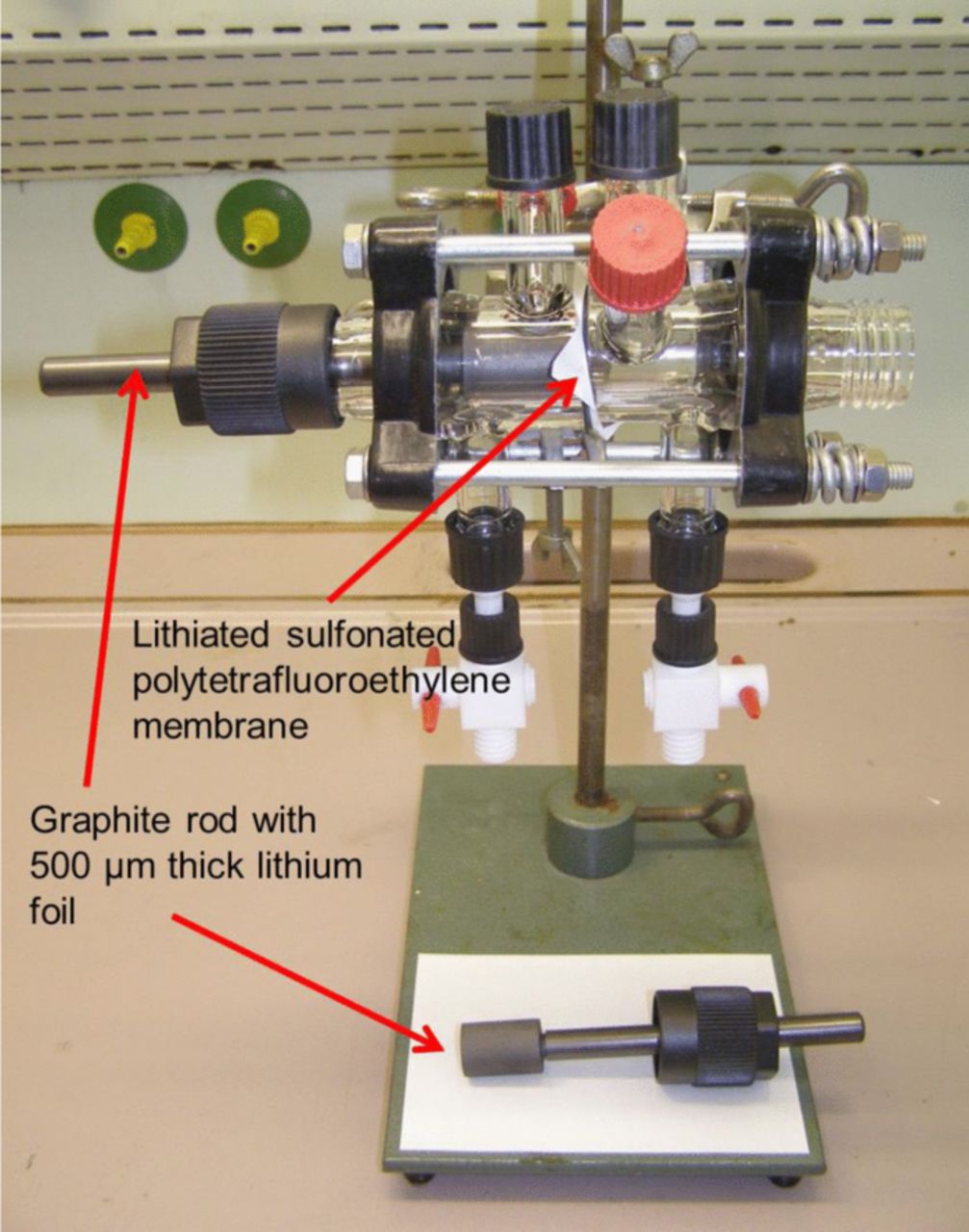
Figure 1. Experimental setup for referencing the Li electrode potentials measured in different electrolyte solutions.
Coin-type cells were chosen to perform the electrochemical measurements. For the CV measurements, a lithium foil (Ø: 18 mm) served as anode setting the potential zero value while a stainless steel foil (Ø: 18 mm) served as working electrode. A glass fiber Whatman GFD separator (Ø: 20 mm) was used and soaked with the electrolyte solution (300 μL) under consideration. The electrolytes were mixtures of the corresponding solvent and LiTFSI in a ratio of 9:1 by weight with additional 1 mg bis(benzene)chromium per 300μL of mixture. A rather slow scan rate of 0.1 mV/s was chosen. CV measurements were carried out using a BioLogic (Grenoble, France) VMP3 Multichannel potentiostat.
For the cycling experiments, a S/C cathode replaced the steel foil as a counter electrode. Typical sulfur loadings amounted to ∼2 mg/cm2. The cells were discharged at first with a rate of 0.02C and consecutively charged with a 0.1C rate and discharged with a 0.15C rate. These experiments were carried out using a Maccor (Tulsa, Oklahoma, USA) battery cycler. The C-rate was calculated on the basis of the sulfur mass loading. Nitrate salts were used in the electrolytes in this case.
Computational Details
All DFT-calculations were performed with the program package TURBOMOLE.52 The Becke-Perdew-86 functional (BP86)53–55 was employed within the efficient RI-J approximation.56 For structure optimizations, an SV(P) basis set was used, whereas single point calculations to obtain molecular input for COSMO-RS57–60 were performed with a meta-hybrid functional M06-2X61–63 in combination with a def2-TZVP basis set. COSMO screening was activated (dielectric constant ɛ = ∞) with the default settings for the distance to the outer solvent sphere for cavity construction (rsolv = 1.3Å) and using the optimized radii for COSMO calculations. COSMO-RS calculations were performed with the COSMOthermsoftware at 25°C.64
Results and Discussion
The Li-S cell voltage and electrochemical reactions involved
As described previously, lithium-sulfur cells are typically cycled in ether-based electrolytes, as they offer a favorable environment for and reasonable stability against the cell chemistry.
Typical charge and discharge curves for such a standard cell are shown in Figure 2. Two distinct discharge plateaus can be distinguished, one at around 2.3–2.4 V and a lower one at round 2.1 V accounting for most of the overall capacity of the cell. The onset of an additional small voltage plateau at ∼1.8 V is ascribed to the electrochemical reduction of the lithium nitrate salt in the electrolyte at the cathode. This phenomenon was observed before.65 As no capacity contributions from the sulfur active material are to be expected in this voltage range any more, the lower cutoff voltage was restricted to 1.9 V in other experiments, as displayed e.g. in Figure 3.
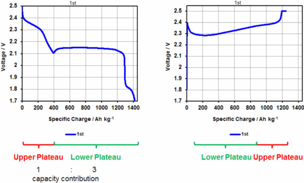
Figure 2. Electrochemical discharge and charge curves for a standard Li-S cell.
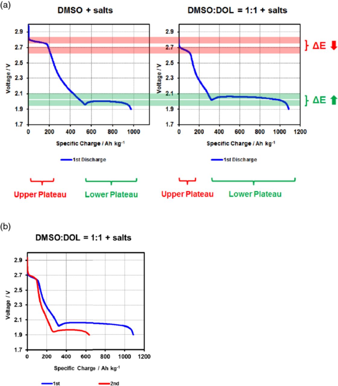
Figure 3. (a) First discharge curves for Li-S cells based on electrolytes containing besides lithium salts pure dimethylsulfoxide (DMSO) as a solvent and a 1:1 mixture of DMSO and dioxolane, respectively. (b) First (rate: 0.02C) and second (rate: 0.15C) discharge of a Li-S cells containing an electrolyte based on a 1:1 mixture of DMSO and dioxolane.
The upper plateau corresponds to the formation of long-chain polysulfides down to an average composition of Li2S4 (at the first dip of the voltage curve separating upper and lower plateau). The lower plateau represents the further reduction of these species to the final reaction products Li2S and Li2S2.31,66
This behavior is drastically changed if the ether-based electrolyte solution described in the previous example is exchanged against an electrolyte containing a polar solvent such as DMSO. Such solvents are usually highly reactive either toward the metallic lithium anode or the polysulfide intermediates or both. These undesired reactions can lead to a polarization of the electrode. Generally such side effects tend to lower the overall measured cell voltage, which means that higher voltages cannot be attributed to these phenomena. Moreover, these solvents can survive the cell chemistry long enough to display some of the effects under consideration here. DMSO based electrolytes were among the ones showing the most pronounced changes in the potential of the characteristic plateaus. This is why the electrochemical behavior of the first discharge curves of both an electrolyte purely based on DMSO as a solvent and another containing both DMSO and DOL to lower the viscosity are exemplarily shown in Figure 3.
Two interesting effects can be directly observed from the two first discharge curves in the respective electrolyte solutions displayed in Figure 3: First of all, it can be clearly seen that the open circuit voltage (OCV) in the DMSO-based electrolytes is considerably higher than in the standard electrolyte displayed in Figure 2. In the electrolyte purely based on DMSO, the OCV amounts to ∼2.8 V as compared to ∼2.4 V for the standard Li-S electrolyte, corresponding to an increase of ∼16–17%. However, the second plateau is not only shorter and the overall capacity lower (which can be ascribed to the higher viscosity of the DMSO), but also the voltage of the second plateau is shifted to lower average discharge voltages as compared to the ether-based electrolyte and in contrast to the upper plateau. While this effect might be partially attributed to the higher viscosity of the DMSO-based electrolyte as well, the explanation seems to be rooted rather in a thermodynamic instead of a kinetic phenomenon: On the second plateau, the final, insoluble reactions products start to precipitate, canceling all solvation effects.
In comparison, the mixed DMSO:DOL electrolyte shows a lowered voltage on the upper, however a higher voltage on the lower plateau, thereby indeed displaying electrochemical properties between the purely DMSO- and standard ether-based electrolytes.
Several explanations for the voltage shifts observed could be raised, which will be considered and discussed in the following.
As the Gibbs and Nernst equations rule the potentials and therefore OCV voltages observed in any electrochemical cell, any change in the voltages measured must be reflected within their terms:
![Equation ([1])](https://content.cld.iop.org/journals/1945-7111/161/9/A1399/revision1/jes_161_9_A1399eqn1.jpg)
![Equation ([2])](https://content.cld.iop.org/journals/1945-7111/161/9/A1399/revision1/jes_161_9_A1399eqn2.jpg)
![Equation ([3])](https://content.cld.iop.org/journals/1945-7111/161/9/A1399/revision1/jes_161_9_A1399eqn3.jpg)
For the reaction
![Equation ([4])](https://content.cld.iop.org/journals/1945-7111/161/9/A1399/revision1/jes_161_9_A1399eqn4.jpg)
the Gibbs free energy amounts to ΔG ∼ −425 kJ/mol while two electrons are exchanged.67 According to equation 1, the voltage to be expected for the electrochemical reactions taking place as indicated in equation 3 is 2.23 V and only one sloping discharge potential should be observed. However, in reality the situation is much more complex due to the multitude of intermediate reaction steps taking place.
As already described in detail before, the reaction between elemental sulfur and lithium is not proceeding via one single step, but several intermediate reactions are involved, linked to the formation of various intermediate polysulfide species. These intermediate reaction steps can be described in a first order approximation by the following relationships:
![Equation ([5])](https://content.cld.iop.org/journals/1945-7111/161/9/A1399/revision1/jes_161_9_A1399eqn5.jpg)
![Equation ([6])](https://content.cld.iop.org/journals/1945-7111/161/9/A1399/revision1/jes_161_9_A1399eqn6.jpg)
This has several important consequences: First of all, the different equilibrium constants for the various reactions involved lead to a corresponding distribution of standard potentials. Therefore, the discharge curve representing the electrochemical reaction between lithium and sulfur does not necessarily proceed along one sloping potential curve, but is expected to involve several steps and plateaus. This is reflected by the observation that the typical discharge curve of a standard lithium sulfur cell contains at least two discharge plateaus. Indeed, at lower temperatures (e.g. −40°C) the discharge profile of a lithium sulfur cell displays more than two plateaus, meaning that several individual sulfur reduction steps can be resolved.68,69
Another important consequence of the multi-step reduction mechanism is the potential influence of the equilibrium constants on the discharge potential of the various reaction steps. It is obvious from equation 6 that increasing the respective equilibrium constant of any electrochemical reaction at consideration will simultaneously lead to a corresponding increase in the potential at which the reaction is happening. This could explain the effects observed for the different electrolytes: Employing an electrolyte providing a much more favorable environment for the formation of polysulfides should shift the equilibrium constant for these reactions to higher values and therefore also increase the cell potential.
However, in order to account for the shifts observed (up to 400 mV between e.g. DMSO as compared to ether-based standard electrolytes) the equilibrium constants would have to shift by several orders of magnitude. Given that ether-based electrolytes are already known for their good polysulfide-dissolving properties this seems rather unlikely. Since the achievable values for the concentrations and activities of the various intermediates are also restricted by the absolute amount of sulfur available in the cell, extremely high ratios in favor of one species are not to be expected.
The most plausible explanation accounting for the effects observed is the following: In contrast to conventional lithium-ion cells were the lithium ions shuttle between two intercalation hosts at the anode and cathode, respectively, in a lithium-sulfur cell lithium cations and sulfur anions are formed from the elements and remain in solution until they precipitate in the form of the final insoluble reaction products lithium sulfide and disulfide.
This means that their solvation energies contribute to the overall reaction enthalpy of the intermediate reaction steps, contributing the energy amount ΔGsolv to the Gibbs free energy ΔG0. The relative shifts in potentials and therefore cell voltage are schematically illustrated in Figure 4.
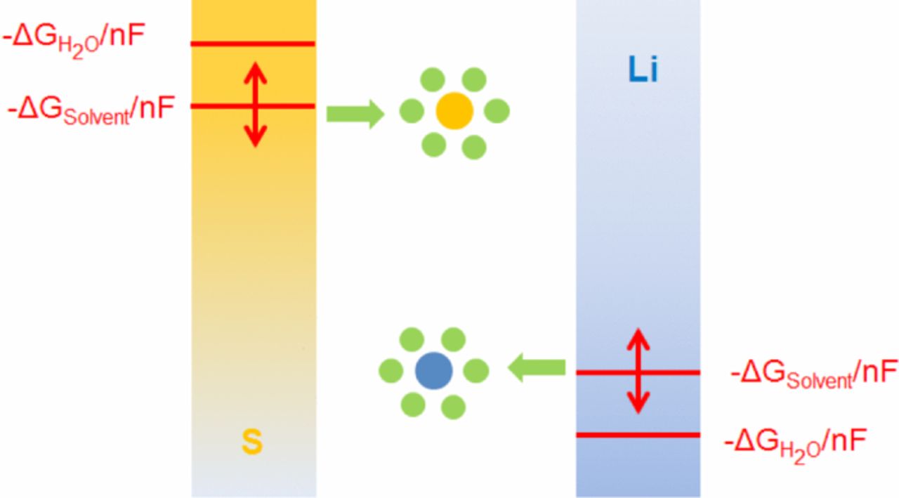
Figure 4. Influence of the solvation energy on the electrode potentials and cell voltages depending on the respective solvent / electrolyte system employed.
This explanation can account for the observations made: As long as the ions stay in solution, their solvation energies contribute to the overall energy gained during the electrochemical reactions taking place within the cell and therefore raise the cell voltage. As soon as lithium sulfide and disulfide start to precipitate on the second plateau, the solvation effect vanishes and the average discharge potential even drops to lower values. In this case, the desolvation energy is correspondingly higher and the overall energy released in the discharge process must be exactly the same irrespective of the electrolyte used as long as the educts and products involved are exactly the same, which is true in the case of solid materials.
The solvation effect for the small, hard lithium cation is expected to be considerably higher than for the negatively charged polysulfide anions.
It is well-known from the literature that the electrode potentials of different redox couples depend on the solvent environment and more specifically, on the free solvation energies of the ions or ion pairs involved. The effect is generally the more pronounced, the smaller and harder the solvated ion under consideration. The potential of rather big cations such as the Rb+ cation only slightly varies in different solvents, so that they can even be used as reference materials for comparing different solvents. At the same time, different solvents can exert quite strong influences on smaller cations such as Li+.70–73
In order to further validate that mainly the solvation energies of the Li+ cations determine the potential shift of the lithium electrode immersed in different solvents, theoretical calculations were carried out. The solvation energies are straightforwardly accessible via quantum chemical calculations. For the inspection of molecular properties, density functional theory (DFT) has proven to be a powerful computational tool. The molecular structures have been optimized at the COSMO/BP86/SV(P) level of theory employing the TURBOMOLE suite of programs. Solvent effects were modeled by the presence of a conducting medium in the COSMO formalism with ɛ = ∞. Gibbs free energies for reactions in solution were determined from a thermodynamic cycle consisting of vaporization of the reactants, reaction in the gas phase and solvation of the products.
Energies required for gas–liquid (and liquid–gas) transitions were calculated with COSMOtherm; single point energy calculations were performed at the M06-2X/def2-TZVP level of theory calculated with the NWChem package. An infinite dilution of reactants and products in the solvent at 25°C was assumed for these calculations.
The obtained complexation energies in the pure solvents relative to the most stable lithium complex in DME/DOL solution ([Li(DME)2(DOL)]+) are depicted in Figure 5.
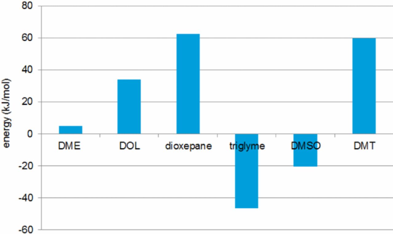
Figure 5. Complexation energies in the pure solvents relative to the most stable lithium complex in DME/DOL solution ([Li(DME)2(DOL)]+). (Abbrev.: DME – dimethoxyethane, DOL – 1,3-dioxolane, Triglyme – triethyleneglycoledimethylether, DMSO – dimethylsulfoxide, DMT – 2,5-dimethoxytetrahydrofurane)
The most stable complexes are formed in case of the very polar electrolyte solvents, such as DMSO, and for chelating agents, such as triglyme. The potential shifts versus the (bis)chromium benzene reference (Table I) can be directly correlated with the calculated complex stabilities. This finding strongly suggests that the changes in the electrode potentials are mostly determined by the solvation (complexation) energies of the respective ions upon formation during the electrochemical charge and discharge reactions within the battery.
Table I. Redox potentials of the (bis)chromium-benzene complex in different electrolytes (values in [V]).
| Solvent | Peak-Potentialcathodic Cr(C6H6)2 | Peak-Potentialanodic Cr(C6H6)2 | Redox Potential Cr(C6H6)2 |
|---|---|---|---|
| DME | 2.15 | 2.30 | 2.23 |
| DOL | 1.95 | 2.16 | 2.06 |
| DEGDME | 2.18 | 2.44 | 2.31 |
| 3-Methylsulfolane | 2.07 | 2.17 | 2.12 |
| 2,5-DimethoxyTHF | 1.85 | 2.25 | 2.07 |
| Dioxepan | 1.89 | 2.22 | 2.06 |
In order to verify these hypothesis as well as to test the influence on the cell potential without the additional effects of the polysulfide anions in a lithium sulfur cell, the difference in the lithium potential in various electrolytes has been investigated employing the measurement setup described in Figure 1.
The potential differences between metallic lithium anodes in different electrolytes
In order to investigate the influence of the solvation energy on the cell voltage, the potential of metallic lithium anodes in various electrolytes was tested.
For this purpose, the glass cell displayed in Figure 1 was used, containing two lithium half-cells. The two electrolyte solutions were separated by a lithiated sulfonated polytetrafluoroethylene membrane in order to mitigate the mixing between the solutions. (A certain amount of swelling of the membrane within the solutions and therefore diffusion and chemical exchange over time between the two chambers cannot be completely prevented with this setup. The observed increases in some curves are due to careful movements of the electrodes, releasing gas bubbles which evolved as a result of the instability of some of the solvents against lithium such as DMSO and residual water).
The concentration of lithium ions in all electrolytes was similar (based on the amount of salt added), so that concentration-derived effects on the potential can be excluded on a first-order approximation.
It can be clearly seen from Figure 6 that between electrolytes of different chemical nature such as ether-based ones and DMSO a substantial voltage can be measured, accounting for the shift in the plateau voltages observed in lithium-sulfur cells.
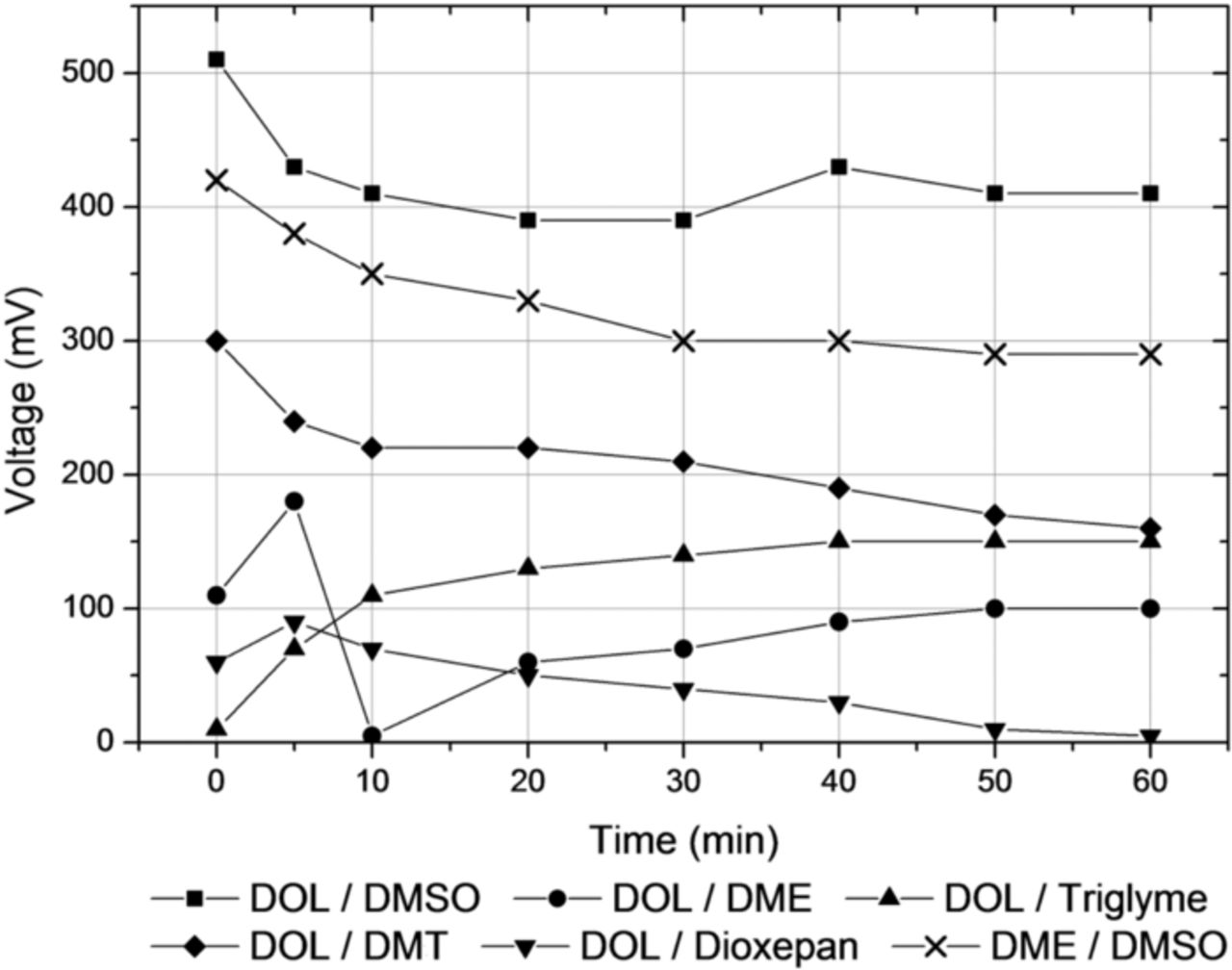
Figure 6. Voltages measured between metallic lithium anodes immersed in different electrolyte solutions and their time evolution. (Abbrev.: DME – dimethoxyethane, DOL – 1,3-dioxolane, Triglyme – triethyleneglycoledimethylether, DMSO – dimethylsulfoxide, DMT – 2,5-dimethoxytetrahydrofurane)
Even if slightly different concentrations and differences in the activities of the cations in the respective solutions can also exert some influence on the potentials measured, it is conceivable that most of the potential differences measured must therefore stem from the differences in solvation energies of the lithium cations in the different solutions.
CV measurements
In addition to the experiments described above which measure the difference in the OCV between lithium electrodes in different electrolyte solutions, another approach was chosen to provide an independent confirmation of these results. Moreover, for the measurement of the potential differences between metallic lithium anodes in different electrolytes a second electrolyte solution is needed and only relative measurements between different solutions are possible. This complicates the direct comparison between various solvents. Therefore, in order to establish a referencing method allowing for fast experiments while providing a "scale" for the effect exerted by the respective solvent under consideration, CV measurements with the electrolyte solutions of interest were performed using lithium as a working electrode.
It is well known from the literature that the solvation effect on ions protected by inert, bulky ligands such as metallocenes is rather small and can be neglected.70 Therefore, any influence on the electrochemical redox potentials of these substances can be expected to be negligible on a first order approximation. Any shift in the observed redox potential between different electrolytes must therefore stem from a change of the reference electrode potential in the respective solutions, e.g. due to a change in the solvation energy. Their characteristic reversible oxidation and reduction peaks and their electrochemically active window within the range of lithium-sulfur batteries turn metallocenes such as e.g. ferrocene into ideal candidates to serve as "inert" reference substances for the experimental investigation of different electrolyte solutions of interest.74,75
Based on these premises, the (bis)chromium-benzene complex was chosen as a reference substance for the CV measurements. It is to some extent soluble in most of the solvents of interest. It shows a characteristic redox potential in a 1:1 DME:DOL solution of ∼2.07 V vs. Li/Li+.
Bulky complexes such as the arene complexes are influenced by solvation effects only to a minor extent, as their chemical interaction with the solvent molecules is weakened due to steric hindrance.
This means that they can serve as a reference substance to indicate the potential shift of a lithium electrode immersed in different electrolytes: If the lithium potential drops (as expected for more polar / chelating solvents) due to an increase in solvation energy, the potential of the signatures (both reduction and oxidation) of the (bis)chromium-benzene complex will apparently shift to higher values and vice versa.
The potential in DOL is indeed lower than in the good chelating agent DME (Table I). Representative CV curves are displayed in Figure 7. The observed differences correspond to the potential difference measured between the lithium electrodes immersed in these two electrolytes (Figure 6).
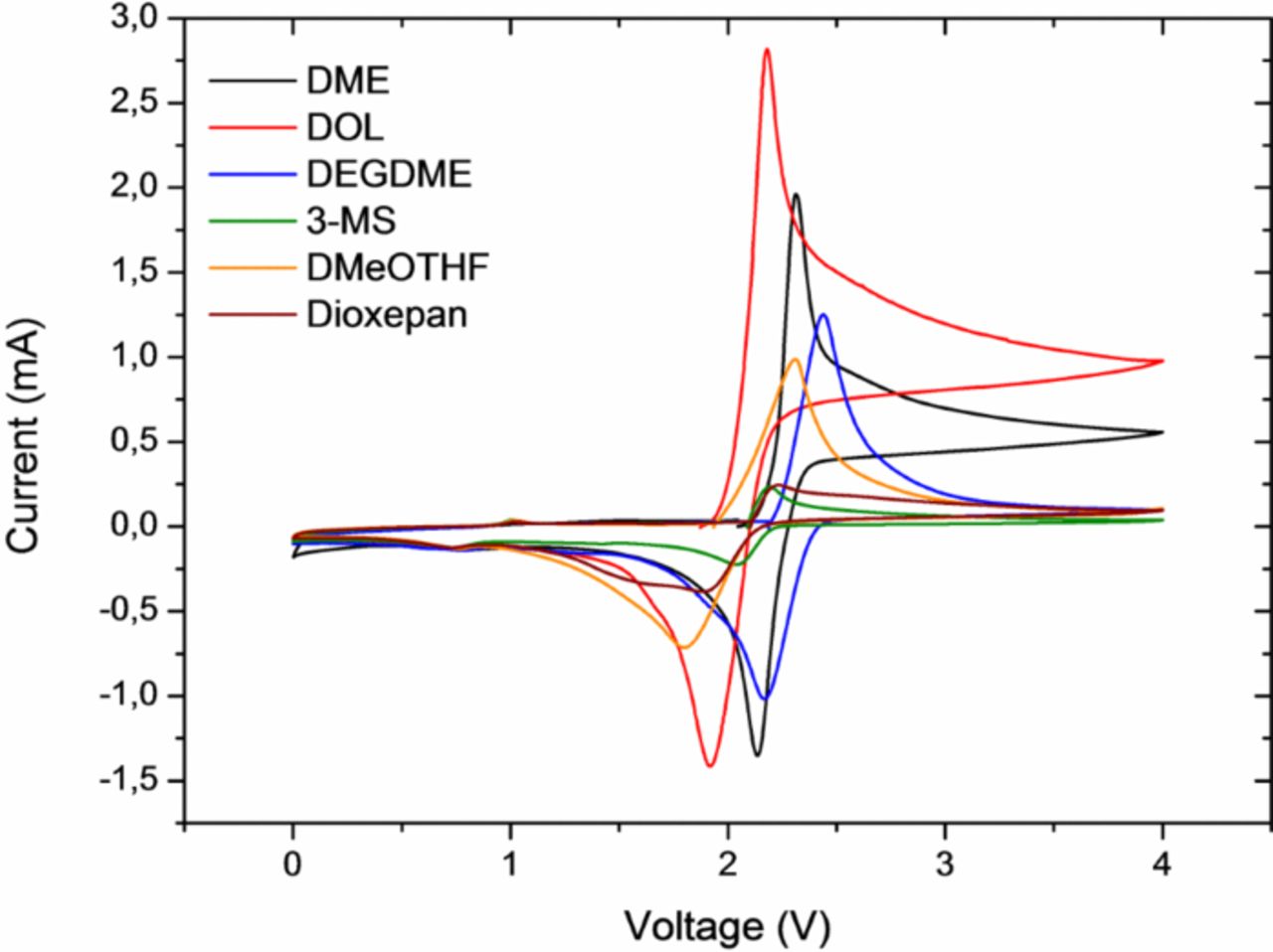
Figure 7. Representative CV curves for different electrolyte solutions containing the (bis)chromium-benzene complex. (Abbrev.: DME – dimethoxyethane, DOL – 1,3-dioxolane, DEGDME – diiethyleneglycoledimethylether, 3-MS – 3-methylsulfolane, DMeOTHF – 2,5-dimethoxytetrahydrofurane)
Finally, these experimental findings are in line with the results of the theoretical calculations, as will be discussed in more detail in the following section.
Assessment of experimental and theoretical findings
Experimental and theoretical efforts have been combined to assess the influence of various organic solvents on the sulfur chemistry taking place within a cell upon cycling. The discharge curves displayed in Figure 2 and Figure 3 illustrate the observed effects exemplarily for a standard and a DMSO-based electrolyte: While the voltage of the upper plateau is considerably increased in the case of the DMSO-based electrolyte, the effect on the lower plateau is smaller and reverse, as the overall effects have to cancel for thermodynamic reasons, as soon as the solid final reaction products start to precipitate. These findings are another indicator that lithium sulfide and/or disulfide start to precipitate from the electrolyte solution with the onset of the second plateau. As can be seen from Figure 3b, the voltage shift in the upper plateau persists for a mixed DMSO/DOL electrolyte also in the second cycle, showing that it is not merely a formation cycle phenomenon. The reduction in the overall capacity of the cell is a result of the increase in rate as well as the limited stability of DMSO-based electrolytes. Comparing Figure 2 and 3 it can be estimated that the observed shift in the upper plateau potential between a DMSO- and DME/DOL-based electrolyte amounts to ∼400–500 mV. This value closely correlates with the OCV voltage measured between two lithium electrodes immersed in a DMSO-based and DME- or DOL-based electrolyte, respectively, as shown in Figure 6.
This result provides evidence that the observed voltage shifts cannot be correlated to the carbon/sulfur cathode or the carbon materials used for sulfur impregnation but are based on ion solvation, as is discussed in more detail in the following.
While the charge and discharge curves displayed in Figure 2 were recorded with a standard electrolyte (mixture of DOL and DME), the measured voltage differences shown in Figure 6 illustrate that there is a considerable voltage difference between DME- and DOL-based electrolytes either, amounting to ∼100 mV.
The calculated differences between the respective complexation energies (Figure 5) fall within the same range, further corroborating the assumptions made. Even if the effects are somewhat overestimated computationally as compared to the experimental values, the calculated values are able to account for the differences between DMSO-, DOL- and DME-based electrolytes. The polar DMSO is the best solvent with respect to complexation of the lithium ions while DOL offers the least favorable environment. The trend observed for the other solvents under consideration and mixtures between them is also reflected.
This holds true for the CV measurements as well (Table I). While the redox potential of the bis(chromium)benzene complex is expected to be hardly influenced by solvation effects as was discussed before, the recorded data seemingly depend on the solvent, as the potential of the lithium reference electrode itself shifts. Therefore, the differences observed for the redox potentials of the benzene complex in the various solvents are a measure for the solvation effects discussed. The observed difference of ∼150–170 mV between the DME- and DOL-based solutions corresponds well to the potential difference measured between the lithium electrodes immersed in these two electrolytes (Figure 6). It should be mentioned that for some of the other solvents the agreement is not quite as good: values for the redox potential measured e.g. in dioxolane, 2,5-dimethoxy-tetrahydrofurane and dioxepane are almost the same, while based on the results from Figure 6 a more pronounced difference is expected. However, it needs to be cautioned that the exact influence of the solvent on the redox potential of the bis(chromium)benzene complex is not known.
However, the trends found for the different experimental approaches are overall in reasonably good agreement and correspond well to the theoretical results. Therefore, it can be concluded that most of the potential shifts observed can be attributed to solvation effects in the different electrolytes. The effects are most pronounced for the small, hard lithium cation. However, solvation effects certainly also exist for the polysulfide species involved, as indicated by earlier experimental findings.36 Their theoretical quantification would yield an even more refined picture and could be the subject of future work.
If it was possible to prevent the final reaction products in a Li-S cell from precipitating, the effect described would be accessible along the full discharge curve of a Li-S cell and in turn, the average discharge potential and therefore energy density of such a battery system could be directly increased by 10–20%. Unfortunately, only protic solvents are able to dissolve substantial amounts of lithium sulfide, which are obviously not a suitable fit in combination with a metallic lithium anode.
As long as precipitation of the final reaction products occurs these effects cannot be exploited to raise the overall voltage of a Li-S cell, as the effects thermodynamically cancel in the course of the charge and discharge reactions. Even if it was possible to preclude precipitation, substantial amounts of electrolyte would be necessary to provide an adequate solvent shell for each of the sulfide or disulfide anions formed. This would severely lower the energy density of such a battery system, more than offsetting the positive effect corresponding to the increase in voltage.
Conclusions
It could be successfully demonstrated that the electrolyte solutions employed in lithium sulfur cells exert a pronounced effect not only on the electrochemical reactions and mechanisms involved but also on the electrode potentials and in turn the overall cell voltage.
These experimental findings are independently supported by theoretical considerations, proving that the solvation energy of the ions in the respective solvents can account for the described effects. The solvation of the rather small and hard lithium ion contributes most to the effects discussed.
The voltage shifts observed are of high interest with respect to creating a better understanding of the complicated cell chemistries involved. For instance, they provide experimental evidence for the immediate onset of precipitation reactions with the start of the second voltage plateau and demonstrate the significant influence of the solvents on the cell chemistry.
In addition, they are of direct practical relevance with respect to polysulfide-based redox-flow batteries discussed in the literature, as in this case only the high plateau representing the formation and reduction of long-chain polysulfide species is of interest while the lower plateau is not exploited due to the precipitation of the insoluble final reaction products.1 This means that an increase in cell voltage would directly translate into a gain in energy density, while the amount of electrolyte is of minor importance in this case.
Acknowledgments
The authors are very grateful to the teams in the laboratories and machine shops both at BASF SE and Sion Power Corp. for their outstanding experimental and technical support.